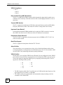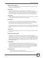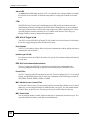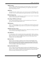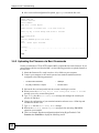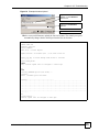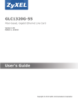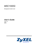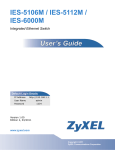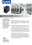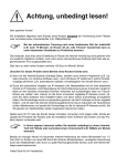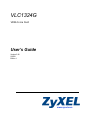
1
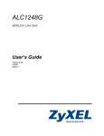
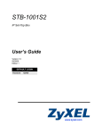
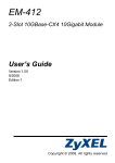
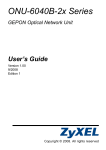
VLC1324G
VDSL2 Line Card
User’s Guide
Version 3.90
5/2008
Edition 1
www.zyxel.com
About This User's Guide
About This User's Guide
Intended Audience
This manual is intended for users of the VLC1324G VDSL2 Line Card and the VSC1224-41
Splitter Card. It describes detailed information about the cards’ features and hardware.
Related Documentation
• IES-5000 and IES-6000 User’s Guides
Refer to the IES-5000 or the IES-6000 User’s Guide for directions on installation,
connections, maintenance, hardware trouble shooting and safety warnings.
• MSC1000G and MSC1024G Management Switch Card User’s Guides
These user’s guides cover the configuration of your IES-5000 or IES-6000. Refer to these
user’s guides for information on your VLC’s default settings.
• ZyXEL Web Site
Please refer to www.zyxel.com for additional support documentation and product
certifications.
User Guide Feedback
Help us help you. Send all User Guide-related comments, questions or suggestions for
improvement to the following address, or use e-mail instead. Thank you!
The Technical Writing Team,
ZyXEL Communications Corp.,
6 Innovation Road II,
Science-Based Industrial Park,
Hsinchu, 300, Taiwan.
E-mail: [email protected]
VLC1324G User’s Guide
3
Document Conventions
Document Conventions
Warnings and Notes
These are how warnings and notes are shown in this User’s Guide.
1
"
Warnings tell you about things that could harm you or your device.
Notes tell you other important information (for example, other things you may
need to configure or helpful tips) or recommendations.
Syntax Conventions
• The VLC1324G may be referred to as the “line card”, the “VLC”, the “device” or the
“system” in this User’s Guide.
• The “VLC1324G”, the “VLC”, the “device” and the “line card” refer to the VLC1324G51 for VDSL over POTS (Annex A). They also refer to the VLC1324G-53 for VDSL over
ISDN (Annex B). Differentiation is made where needed.
• “IES” refers to the IES-5000 or IES-6000 system, including the main chassis and all
associated cards.
• “MSC” refers to the MSC1000GA management switch card.
• Product labels, screen names, field labels and field choices are all in bold font.
• A key stroke is denoted by square brackets and uppercase text, for example, [ENTER]
means the “enter” or “return” key on your keyboard.
• “Enter” means for you to type one or more characters and then press the [ENTER] key.
“Select” or “choose” means for you to use one of the predefined choices.
• A right angle bracket ( > ) within a screen name denotes a mouse click. For example,
Maintenance > Log > Log Setting means you first click Maintenance in the navigation
panel, then the Log sub menu and finally the Log Setting tab to get to that screen.
• Units of measurement may denote the “metric” value or the “scientific” value. For
example, “k” for kilo may denote “1000” or “1024”, “M” for mega may denote “1000000”
or “1048576” and so on.
4
VLC1324G User’s Guide
Safety Warnings
Safety Warnings
1
For your safety, be sure to read and follow all warning notices and instructions.
• Do NOT use this product near water, for example, in a wet basement or near a swimming
pool.
• Do NOT expose your device to dampness, dust or corrosive liquids.
• Do NOT store things on the device.
• Do NOT install, use, or service this device during a thunderstorm. There is a remote risk
of electric shock from lightning.
• Connect ONLY suitable accessories to the device.
• Do NOT open the device or unit. Opening or removing covers can expose you to
dangerous high voltage points or other risks. ONLY qualified service personnel should
service or disassemble this device. Please contact your vendor for further information.
• Make sure to connect the cables to the correct ports.
• Place connecting cables carefully so that no one will step on them or stumble over them.
• Always disconnect all cables from this device before servicing or disassembling.
• Do not use the device outside, and make sure all the connections are indoors. There is a
remote risk of electric shock from lightning.
• Do NOT obstruct the device ventilation slots, as insufficient airflow may harm your
device.
• Warning! To avoid risk of electric shock, remove only one card at a time and do not place
fingers or objects inside the chassis. Cover empty slots with slot covers.
This product is recyclable. Dispose of it properly.
VLC1324G User’s Guide
5
Safety Warnings
6
VLC1324G User’s Guide
Table of Contents
Table of Contents
About This User's Guide .......................................................................................................... 3
Document Conventions............................................................................................................ 4
Safety Warnings........................................................................................................................ 5
Table of Contents...................................................................................................................... 7
List of Figures ........................................................................................................................... 9
List of Tables........................................................................................................................... 11
Part I: Introduction, Specifications and Troubleshooting .................. 13
Chapter 1
VLC Overview.......................................................................................................................... 15
1.1 VLC Overview ...................................................................................................................... 15
1.2 VDSL2 Profiles Overview .................................................................................................... 15
1.3 Key Features ....................................................................................................................... 15
1.4 Front Panel of VLC ............................................................................................................. 20
1.5 Ports and LEDs of VLC ....................................................................................................... 21
1.5.1 Ports ........................................................................................................................... 21
1.5.2 LEDs ......................................................................................................................... 21
1.6 VSC1224-41 POTS Splitter ................................................................................................. 21
Chapter 2
VLC Specifications ................................................................................................................. 23
2.1 VLC Product Specifications ................................................................................................. 23
2.2 VLC Firmware Naming Conventions ................................................................................... 25
2.3 Telco-50 Connector Pin Assignments .................................................................................. 25
2.4 Wire Gauge Specifications .................................................................................................. 28
2.5 Console Cable Pin Assignments ......................................................................................... 28
2.6 VSC1224-41 ........................................................................................................................ 29
2.7 VSC1224-43U ..................................................................................................................... 29
Chapter 3
VLC Troubleshooting.............................................................................................................. 31
3.1 The SYS or PWR LED Does Not Turn On ........................................................................... 31
3.2 The ALM LED Is On ............................................................................................................ 31
VLC1324G User’s Guide
7
Table of Contents
3.3 VDSL2 Data Transmission .................................................................................................. 32
3.4 Local Server ........................................................................................................................ 32
3.5 Data Rate ............................................................................................................................ 32
3.6 The Line Card is Not Manageable ....................................................................................... 33
3.6.1 Uploading the Default Configuration File via Boot Commands .................................. 33
3.6.2 Uploading the Firmware via Boot Commands ............................................................ 34
Part II: Appendices and Index............................................................... 37
Appendix A Legal Information ................................................................................................ 39
Appendix B Customer Support............................................................................................... 43
Index......................................................................................................................................... 49
8
VLC1324G User’s Guide
List of Figures
List of Figures
Figure 1 Front Panel ............................................................................................................................... 21
Figure 2 Front Panel of VSC1224-41 ..................................................................................................... 21
Figure 3 VLC Ports 1-24 Telco-50 Connector Pin Assignments ........................................................... 25
Figure 4 IES-5000/5005 Cable Telco-50 Pin Assignments (VLC End) ................................................... 26
Figure 5 IES-5000/5005 Cable Telco-50 Pin Assignments (Splitter Card End) ...................................... 27
Figure 6 IES-6000 Cable Telco-50 Pin Assignments (VLC End) ............................................................ 27
Figure 7 IES-6000 Cable Telco-50 Pin Assignments (Splitter End) ........................................................ 28
Figure 8 Console Cable Mini RJ-11 Male Connector ............................................................................. 29
Figure 9 Example Xmodem Upload ........................................................................................................ 33
Figure 10 Example Xmodem Upload ...................................................................................................... 35
VLC1324G User’s Guide
9
List of Figures
10
VLC1324G User’s Guide
List of Tables
List of Tables
Table 1 VDSL2 Profile Maximum Transfer Rates .................................................................................. 15
Table 2 Front Panel Ports ...................................................................................................................... 21
Table 3 LED Descriptions ...................................................................................................................... 21
Table 4 VLC Specifications .................................................................................................................... 23
Table 5 VLC Telco-50 Connector Pin Assignments ............................................................................... 25
Table 6 Wire Gauge Specifications ........................................................................................................ 28
Table 7 Console Cable Connector Pin Assignments ............................................................................. 29
Table 8 VSC1224-41 CO Impedance Splitter Card Specifications ........................................................ 29
Table 9 SYS LED Troubleshooting ........................................................................................................ 31
Table 10 ALM LED Troubleshooting ...................................................................................................... 31
Table 11 VDSL2 Data Transmission Troubleshooting ........................................................................... 32
Table 12 Local Server Troubleshooting ................................................................................................. 32
Table 13 SYNC-rate Troubleshooting .................................................................................................... 32
VLC1324G User’s Guide
11
List of Tables
12
VLC1324G User’s Guide
P ART I
Introduction,
Specifications and
Troubleshooting
VLC Overview (15)
VLC Specifications (23)
VLC Troubleshooting (31)
13
14
CHAPTER
1
VLC Overview
This chapter introduces the VDSL2 line card's general features, default settings and hardware.
1.1 VLC Overview
The VLC VDSL2 Line Card is perfect for ISPs or large building applications seeking to
provide high bandwidth broadband services to subscribers while minimizing costs. One VLC
provides VDSL2 service for 24 subscribers over existing telephone wiring, thus avoiding the
cost and hassle of installing new wiring.
The line from the user carries both the VDSL2 and the voice signals. For each line, the splitter
card separates the high frequency VDSL2 signal from the voice band signal and feeds the
VDSL2 signal to the line card, while the voice band signal is diverted to the central office
switch or PBX (Private Branch Exchange).
Use the Telco-50 connector pin assignments in Section 2.3 on page 25 along with the
directions and safety warnings in the IES User’s Guide to install the line card and make the
necessary connections.
1.2 VDSL2 Profiles Overview
Here are the VDSL2 maximum transmission rates that the VLC supports at the time of writing.
The actual transfer rates will vary depending on what the subscriber’s device supports, the line
conditions and the connection distance.1
Table 1 VDSL2 Profile Maximum Transfer Rates
VDSL2 PROFILE
MAXIMUM DOWNSTREAM
MAXIMUM UPSTREAM
8a/b/c/d
85 Mbps
18 Mbps
12a/b
85 Mbps
50 Mbps
17a
100 Mbps
50 Mbps
1.3 Key Features
Here is a partial list of the VLC’s features.
1.
These are the highest link rates attained in testing. Actual data transfer rates will vary. These rates are for a
single port. The ports cannot all simultaneously link up at these rates.
VLC1324G User’s Guide
15
Chapter 1 VLC Overview
VDSL2 Compliance
• ITU-T
-G.993.2
-G.994.1
Discrete Multi-Tone (DMT) Modulation
The VLC is a DMT-based VDSL2 solution which dynamically adapts the bit transfer rate to
conditions on the local loop. This allows the line card to sustain high performance even over
noisy lines.
Transmit PSD Notches
The VLC supports the transmission of PSD (Power Spectral Density) notches at RFI (Radio
Frequency Interference) bands. This reduces the effects of strong radio sources nearby.
Upstream Power Backoff
Upstream Power Backoff (UPBO) methods can be applied to VDSL2 networks, in order to
solve FEXT (Far End Cross (X) Talk) noise effects in distributed environments.
Downstream Power Back-Off
The VLC1324G-51 supports the downstream power back-off (DPBO) in ITU-T G.997.1 to
reduce far-end crosstalk.
Band Plan Support
The VLC supports the band plans defined in ITU-T G.993.2.
Alarm Profiles
The system allows you to customize the priority levels of individual alarms and the alarm
severity threshold for recording alarms on an individual port(s). The VLC also includes a DSL
error (ES, SES, UAS) monitoring and alarm reporting mechanism.
VDSL2 Profiles
Profiles allow you to configure VDSL2 ports efficiently. You can configure all of the VDSL2
ports with the same profile, thus removing the need to configure the VDSL2 ports one-by-one.
You can also change an individual VDSL2 port by assigning it a different profile. The VLC
supports the following VDSL2 profiles:
•
8a
•
8b
•
8c
•
8d
•
12a
•
12b
•
17a
• The DS1 frequency band of the 17a profile starts at 138 kHz and the edge frequency of the
upper band of the 17a profile is 17.664 MHz.
• The VDSL2 profiles are programmable and automatically adapt according to the line
condition of each VDSL2 line.
16
VLC1324G User’s Guide
Chapter 1 VLC Overview
VDSL2 to ADSL2+ Fallback
The VLC can automatically use ADSL2+ for connections where VDSL2 training fails. This
allows a longer connection distance.
Spectral Mask
PSD (Power Spectral Density) defines the distribution of a VDSL line’s power in the
frequency domain. A PSD mask is a template that specifies the maximum allowable PSD for a
line. The VLC transmitter signal complies with the Power Spectrum Density (PSD) mask
specified in ITU-T G.993.2 and supports masks EU32_D32, EU36_D48, and EU40_D48.
Latency Mode
The VLC supports the latency path function specified in ITU-T G.993.2 and you can manually
configure the payload transfer delay for interleaved transmissions.
Rate Adaption
Rate adaption lets the VLC adjust from the configured transmission rate to the attainable
transmission rate automatically depending on the line quality. The VDSL transmission rate
then stays at the new rate or adjusts if line quality improves or deteriorates.
The rate adaptation conforms to ITU-T G.993.2 and G.997.1 and is manually configurable and
can adjust automatically based on the line quality as determined by the Signal-to-Noise Ratio
(SNR).
Trellis Coding
The VLCuses Trellis coding (as specified in ITU-T G.993.2) to help reduce the noise in VDSL
transmissions.
Impulse Noise Protection (INP)
Short impulses from external sources may cause bursts of errors which could impact
multimedia (ex. voice, video, or picture) quality. The VLC’s VDSL2 supports Impulse Noise
Protection (INP) as defined ITU-T G.993.2. The VLC’s impulse noise protection provides the
ability to correct errors regardless of the number of errors in an errored DMT (Discrete MultiTone) symbol. You can configure the minimum impulse noise protection to provide up to 16
DMT symbols protection.
Loop Diagnostic
The VLC supports the loop diagnostic function specified in ITU-T G.993.2. The test
parameters include quiet line noise, signal-to-noise ratio, loop attenuation, signal attenuation,
signal-to-noise ratio margin, attainable net data rate, and far-end actual aggregate transmit
power. After completing the loop diagnostic function, the VLC displays the test results and
automatically returns to the normal state to be ready for initialization.
System Monitoring
• System status (link status, rates, statistics counters)
• Configurable temperature and voltage monitoring thresholds and alarm reports.
VLC1324G User’s Guide
17
Chapter 1 VLC Overview
Alarm LED
An ALM (alarm) LED lights when the VLC is overheated or the voltage readings are outside
the tolerance levels and turns off when the temperature or voltage has returned to a normal
level.
CFM
The IEEE 802.1ag Connectivity Fault Management (CFM) specification allows network
administrators to identify and manage connection faults. Through discovery and verification
of the path, CFM can detect, analyze and isolate connectivity faults in bridged LANs. This is
especially helpful when the route between a CO VDSL switch and one of its CPE goes
through switches owned by independent organizations.
IEEE 802.1Q Tagged VLAN
Your VLC uses the IEEE 802.1Q Tagged VLAN (Virtual Local Area Network), which allows
it to deliver tagged/untagged frames to and from its ports.
Port Isolation
The VLC's port isolation feature allows each port to communicate with the uplink port but not
communicate with each other.
Isolation (per-VLAN)
Use isolation to block the VDSL2 subscribers in a specific VLAN from sending traffic directly
to each other.
IEEE 802.1x Port-based Authentication
The VLC supports the IEEE 802.1x standard for centralized user authentication and
accounting management through an optional network authentication (RADIUS) server.
Packet Filter
The VLC supports packet filtering based on protocol. You can configure the VLC to accept all
packets, accept PPPoE packets only or block any combination of the following protocols: IP,
ARP, DHCP, EAPOL, PPPoE, NetBios or IGMP.
MAC (Media Access Control) Filter
Use the MAC filter to deny or accept incoming frames based on MAC (Media Access Control)
address(es) or OUI (Organizational Unit Identifier) that you specify. You may enable/disable
the MAC filter on specific ports. You may specify up to ten MAC addresses per port.
MAC Count Limit
You can limit the number of MAC addresses that may be dynamically learned on a port. You
may enable/disable the MAC count filter on individual ports.
18
VLC1324G User’s Guide
Chapter 1 VLC Overview
IGMP Snooping
The VLC supports IGMP snooping enabling group multicast traffic to be only forwarded to
ports that are members of that group; thus allowing you to significantly reduce multicast
traffic passing through your VLC.
IGMP Filter
The IGMP filter defines multicast groups a port can join. You can create IGMP filter profiles
which allow access to a multicast group, then assign the IGMP filter to a specific VDSL2 port.
Multicast Group Limit
You can limit the number of multicast groups a subscriber on a port can join. You may enable/
disable the multicast group limit on individual ports.
Discarding of IGMP Query Messages
The VLC discards IGMP query messages received from subscriber ports. This prevents
subscribers from hosting IGMP multicast servers.
IGMP Statistics
The VLC records the number of active users in an IGMP multicast channel (multicast group).
The VLC also records IGMP message statistics on a per port basis to ease management and
troubleshooting.
IGMP Message Rate Limiting
The VLC can limit how many IGMP message packets a subscriber can send per second. This
prevents subscribers from flooding the multicast server.
Static Multicast
Use static multicast to allow incoming frames based on multicast MAC address(es) that you
specify. This feature can be used in conjunction with IGMP snooping to allow multicast MAC
address(es) that are not learned by IGMP snooping. You can use static multicast to pass
routing protocols, such as RIP and OSPF.
Multicast VLAN
Multicast VLAN is designed for applications (such as Media-on-Demand (MoD)) using
multicast traffic across an Ethernet ring-based service provider network. Multicast VLAN
allows one single multicast VLAN to be shared among different subscriber VLANs on the
network. This improves bandwidth utilization by reducing multicast traffic in the subscriber
VLANs and simplifies multicast group management.
Multicast Bandwidth Control
The VLC supports static bandwidth control for multicast traffic. Bandwidth limits can be
assigned to multicast channels. During IGMP snooping, the system checks the total bandwidth
usage to see if it exceeds the specified limit. If the specified limits are reached, the system
restricts the joining of multicast groups on a per port basis.
VLC1324G User’s Guide
19
Chapter 1 VLC Overview
DHCP Relay
DHCP (Dynamic Host Configuration Protocol RFC 2131 and RFC 2132) allows individual
computers to obtain TCP/IP configuration at start-up from a server. You can configure the
system as a DHCP relay agent to have another DHCP server provide TCP/IP configuration for
the clients. In addition, you can set the system to forward client DHCP requests to specific
DHCP servers based on the VLAN ID. You can also specify up to two DHCP servers for each
VLAN to provide failover protection.
Rate Limiting
Rate limiting on the subscriber ports allows service providers to offer tiered service in
increments of 64 Kbps. This service differentiation is not only to fulfill the needs of different
customers, but also to provide a network infrastructure that combines guaranteed performance
and flexibility in service provisioning.
DHCP Relay Option 82
The system supports DHCP relay agent82 (RFC 3046) that adds additional information to
client DHCP requests that the MSC relays to a DHCP server. It also supports adding the suboption 2 (Remote ID) with additional information.
DHCP Snooping
DHCP snooping allows the system to identify packets with DHCP server assigned IP
address(es) and block access of devices using unknown IP addresses on a subscriber port. You
can also manually add static IP addresses to the DHCP snooping table.
Anti-IP Address Spoofing
With DHCP snooping, a line card records which IP addresses are assigned on each port. The
line card drops packets from a device using a different IP address.
Anti-MAC Address Spoofing
The VLC checks to make sure the MAC addresses of the devices connected to the DSL ports
are not the same as MAC addresses of devices connected to the Ethernet network. This
protects the network from disruptions of service caused by subscriber devices spoofing the
MAC address of ISP servers.
Transparent LAN Service (TLS)
Use TLS (also known as VLAN stacking) to add an outer VLAN tag to the inner IEEE 802.1Q
tagged frames that enter the network. This allows a service provider to provide different
services based on specific VLANs, for many different customers.
1.4 Front Panel of VLC
The figure below shows the front panel of the VLC.
20
VLC1324G User’s Guide
Chapter 1 VLC Overview
Figure 1 Front Panel
1.5 Ports and LEDs of VLC
These are the details of the VLC ports and LEDs.
1.5.1 Ports
The following table describes the port labels on the front panel.
Table 2 Front Panel Ports
LABEL
DESCRIPTION
CONSOLE
For troubleshooting purposes, this mini RJ-11port connects to a computer
when the line card is not manageable from the MSC.
1-24
These Telco-50 connectors are for connecting the VLC to the splitter cards.
1.5.2 LEDs
The following table describes the LED indicators on the front panel of the VLC.
Table 3 LED Descriptions
LED
COLOR
STATUS
DESCRIPTION
PWR
Green
On
The line card is turned on.
Off
The line card is off.
Blinking
The line card is rebooting and performing self-diagnostic
tests.
On
The line card is on and functioning properly.
Off
The power is off or the line card is malfunctioning.
On
There is a hardware failure or alarm.
Off
The line card is functioning normally.
SYS
ALM
Green
Red
1.6 VSC1224-41 POTS Splitter
Figure 2 Front Panel of VSC1224-41
A 24 port POTS splitter is used to differentiate analog signal from the VDSL2 band. The
VLC1324G-51 uses the VSC1224-41 and the VLC1324G-53 uses the VSC1224-43U. The
splitter is installed in the splitter chassis. See the IES User’s Guide for installation instructions.
VLC1324G User’s Guide
21
Chapter 1 VLC Overview
22
VLC1324G User’s Guide
CHAPTER
2
VLC Specifications
This chapter gives details about the line card hardware and features.
2.1 VLC Product Specifications
Table 4 VLC Specifications
Dimensions
390.6 mm (W) x 240.0 mm (D) x 13.8 mm (H)
Weight
1 kg
Interface
•
•
Operation Temperature
-40º C ~ 65º C
Storage Temperature
-40º C ~ 70º C
Operation Humidity
10% ~ 90% RH (non-condensing)
Storage Humidity
10% ~ 95% RH (non-condensing)
Power Consumption
Less than 70 Watts
Power Input
-36~-72 VDC (typical -48 VDC)
Fuse Rating
Number of fuses: 1
Type: T
Amps: 4
Volts AC: 250
Dimensions: 5mm (D) x 20mm (L)
VDSL2 Compliance
ITU-T VDSL2 Standard
• G.993.2
• G.994.1
MAC Address Table
4 K entries
Max. Number of IGMP
Filter Profiles
128
Supported VDSL2
Profiles
8a, 8b, 8c, 8d, 12a, 12b, 17a
Number of VLANs per
card
Up to 1 K individual VLANs
External Splitter Details
The VLC1324G-51 uses the VSC1224-41 splitter.
The VLC1324G-53 uses the VSC1224-43U splitter.
The splitter has a front panel Telco-50 connector for connecting to the VLC.
Supported Band Plans
ITU-T G.993.2 Annex A
ITU-T G.993.2 Annex B (bandplans 997 and 998)
VLC1324G User’s Guide
One Telco-50 connector: 24 VDSL2 Ports
One mini RJ11 console port for local management
23
Chapter 2 VLC Specifications
Table 4 VLC Specifications
24
Certifications
RoHS & WEEE compliant
NEBS compliant
ETSI 300-019
K.20
Safety
EN60950-1
EN41003-1
ETSI300-386
CSA60950-1
UL60950-1
IEC60950-1
EMC
FCC Part 15 Class A
EN55022 Class A
EN55024 Class A
ETSI 300 386
Network Management
•
•
•
•
•
•
Local debug function through a RS-232 port
Web-based configurator through MSC
SNMP v1, v2c and v3 based support through MSC
Remote debug through MSC (Telnet)
Status display and event report
Multi-level login through MSC
MIB
•
•
•
•
•
•
•
RFC1213 SNMP MIB II
RFC1493 Bridge MIB·
RFC1643 Ethernet MIB·
RFC2674 Q MIB·
VDSL2 Line MIB (RFC3728)·
RFC1757 RMON MIB, group 1, 2, 3, 9
ZyXEL proprietary MIB.
- MIB for VDSL2 uplink/downlink SNR
- MIB for VDSL2 interface Tx/Rx power
- MIB for IGMP statistics per subscriber interface and per multicast
VLAN basis, which at least include counters of IGMP join, IGMP leave
and active multicast group(s)
- MIB for counters of active users on a per-multicast group basis
- MIB for VDSL2 line includes far-end and near-end Error Second (ES),
Severely Error Second (SES) and Unavailable Second (UAS) at VTUO, and near-end ES, SES and UAS at VTU-R
- MIB for VDSL2 port includes the far-end and near-end Code Violation
(incorrect Cyclic Redundancy Check, CRC) at VTU-O, and near-end
Code Violation at VTU-R
Other Features
•
•
•
•
•
•
•
•
•
•
•
•
•
•
•
Anti-IP Address Spoofing
Anti-MAC Address Spoofing
MAC Filtering
MAC Count Limiting
Hardware-based Multicasting
Multicast Group Limit
IGMP Message Rate Limiting
IEEE 802.1Q VLAN Tagging
IEEE 802.1p CoS with Priority Queuing
IGMP v1 & v 2 Snooping
DHCP Snooping
IEEE 802.1x Port-based Authentication
ACL profile
IEEE 802.1p Priority Mapping Sets
Transmit PSD
VLC1324G User’s Guide
Chapter 2 VLC Specifications
2.2 VLC Firmware Naming Conventions
A firmware version includes the model code and release number as shown in the following
example:
Firmware Version: V3.90(AYL.0) , V3.90(BBW.0) ,
“AYL” or “BBW” is the model code.
• "AYL" denotes the VLC1324G-51 for VDSL over POTS (Annex A).
• "BBW" denotes the VLC1324G-53 for VDSL over ISDN (Annex B).
“0” is the firmware’s release number. This varies as new firmware is released. Your firmware’s
release number may not match what is displayed in this User’s Guide.
2.3 Telco-50 Connector Pin Assignments
The following figures and table describe the pin assignments for the VLC’s Telco-50
connector. The splitter card’s Telco-50 connector and the USER and CO hardware Telco-50
connectors on the rear panel of the splitter chassis also use the same pin assignments.
Figure 3 VLC Ports 1-24 Telco-50 Connector Pin Assignments
Table 5 VLC Telco-50 Connector Pin Assignments
PORTS 1-24
Pin 1
NULL
Pin 26 NULL
Pin 2
Ring Port 24
Pin 27 Tip Port 24
Pin 3
Ring Port 23
Pin 28 Tip Port 23
Pin 4
Ring Port 22
Pin 29 Tip Port 22
Pin 5
Ring Port 21
Pin 30 Tip Port 21
Pin 6
Ring Port 20
Pin 31 Tip Port 20
Pin 7
Ring Port 19
Pin 32 Tip Port 19
VLC1324G User’s Guide
25
Chapter 2 VLC Specifications
Table 5 VLC Telco-50 Connector Pin Assignments (continued)
PORTS 1-24
Pin 8
Ring Port 18
Pin 33 Tip Port 18
Pin 9
Ring Port 17
Pin 34 Tip Port 17
Pin 10
Ring Port 16
Pin 35 Tip Port 16
Pin 11
Ring Port 15
Pin 36 Tip Port 15
Pin 12
Ring Port 14
Pin 37 Tip Port 14
Pin 13
Ring Port 13
Pin 38 Tip Port 13
Pin 14
Ring Port 12
Pin 39 Tip Port 12
Pin 15
Ring Port 11
Pin 40 Tip Port 11
Pin 16
Ring Port 10
Pin 41 Tip Port 10
Pin 17
Ring Port 9
Pin 42 Tip Port 9
Pin 18
Ring Port 8
Pin 43 Tip Port 8
Pin 19
Ring Port 7
Pin 44 Tip Port 7
Pin 20
Ring Port 6
Pin 45 Tip Port 6
Pin 21
Ring Port 5
Pin 46 Tip Port 5
Pin 22
Ring Port 4
Pin 47 Tip Port 4
Pin 23
Ring Port 3
Pin 48 Tip Port 3
Pin 24
Ring Port 2
Pin 49 Tip Port 2
Pin 25
Ring Port 1
Pin 50 Tip Port 1
The following graphics show pin assignments for the Telco-50 connectors on the cables that
connect the VLC to a splitter card in the splitter chassis.
Figure 4 IES-5000/5005 Cable Telco-50 Pin Assignments (VLC End)
26
VLC1324G User’s Guide
Chapter 2 VLC Specifications
Figure 5 IES-5000/5005 Cable Telco-50 Pin Assignments (Splitter Card End)
Figure 6 IES-6000 Cable Telco-50 Pin Assignments (VLC End)
VLC1324G User’s Guide
27
Chapter 2 VLC Specifications
Figure 7 IES-6000 Cable Telco-50 Pin Assignments (Splitter End)
2.4 Wire Gauge Specifications
AWG (American Wire Gauge) is a measurement system for wire that specifies its thickness.
As the thickness of the wire increases, the AWG number decreases.
Table 6 Wire Gauge Specifications
WIRE TYPE
REQUIRED AWG NO. (DIAMETER)
Telephone Wire
26 or larger
2.5 Console Cable Pin Assignments
The following diagram and chart show the pin assignments of the console cable.
28
VLC1324G User’s Guide
Chapter 2 VLC Specifications
Figure 8 Console Cable Mini RJ-11 Male Connector
Table 7 Console Cable Connector Pin Assignments
MINI RJ-11 MALE
Pin 2: TXD
Pin 3: RXD
Pin 4: GND
2.6 VSC1224-41
The following table lists the splitter card specifications.
Table 8 VSC1224-41 CO Impedance Splitter Card Specifications
COUNTRY
POTS
Taiwan
900 Ω
Others
600 Ω
2.7 VSC1224-43U
The VSC1224-43U provides an impedance of 135 ohms and 150 ohms for ISDN.
VLC1324G User’s Guide
29
Chapter 2 VLC Specifications
30
VLC1324G User’s Guide
CHAPTER
3
VLC Troubleshooting
This chapter covers potential problems and possible remedies. After each problem description,
some steps are provided to help you to diagnose and solve the problem.
3.1 The SYS or PWR LED Does Not Turn On
Table 9 SYS LED Troubleshooting
STEPS
CORRECTIVE ACTION
1
Make sure the power wires are properly connected to the power supply and the power
supply is operating normally. Make sure you are using the correct power source (refer to
the IES User’s Guide for details).
2
Make sure the power wires are connected properly.
3
Make sure the line card is properly installed.
4
The LED itself or the unit may be faulty; contact your vendor.
3.2 The ALM LED Is On
The ALM (alarm) LED lights when the line card is overheated or the voltage readings are
outside the tolerance levels.
Table 10 ALM LED Troubleshooting
STEPS
CORRECTIVE ACTION
1
Use the sys monitor show command to verify the cause of the alarm. See step 2 if the
unit is overheated, and step 3 if the voltages are out of the allowed ranges.
2
Ensure that the IES is installed in a well-ventilated area and that normal operation of the
fans is not inhibited. Keep the bottom, top and all sides clear of obstructions and away from
the exhaust of other equipment.
3
If the voltage levels are outside the allowed range, take a screen shot of the sys
monitor show command display and contact your vendor.
VLC1324G User’s Guide
31
Chapter 3 VLC Troubleshooting
3.3 VDSL2 Data Transmission
The VDSL2 link is up, but data cannot be transmitted.
Table 11 VDSL2 Data Transmission Troubleshooting
STEPS
CORRECTIVE ACTION
1
Check the line card’s port isolation settings.
If the subscriber is having problems with video or other high-bandwidth services, make
sure the line card’s VDSL2 port’s data rates are set high enough.
2
Check the VLAN configuration.
3
Ping the MSC from the computer behind the VDSL2 modem or router.
If you cannot ping, connect a VDSL2 modem to a VDSL2 port (that is known to work).
If the VDSL2 modem or router works with a different VDSL2 port, there may be a problem
with the original port. Contact the distributor.
If using a different port does not work, try a different VDSL2 modem or router with the
original port.
3.4 Local Server
The computer behind a VDSL2 modem or router cannot access a local server connected to the
line card.
Table 12 Local Server Troubleshooting
STEPS
CORRECTIVE ACTION
1
Refer to Section 3.3 on page 32 to make sure that the subscriber is able to transmit to the
line card.
2
Make sure the computer behind the DSL device has the correct gateway IP address
configured.
3
Check the VLAN configuration.
4
Check the cable and connections between the line card and the local server.
5
Try to access another local server.
If data can be transmitted to a different local server, the local server that could not be
accessed may have a problem.
3.5 Data Rate
The SYNC-rate is not the same as the configured rate.
Table 13 SYNC-rate Troubleshooting
32
STEPS
CORRECTIVE ACTION
1
Connect the VDSL2 modem or router directly to the VDSL2 port using a different telephone
wire.
2
If the rates match, the quality of the telephone wiring that connects the subscriber to the
VDSL2 port may be limiting the speed to a certain rate.
If they do not match when a good wire is used, contact the distributor.
VLC1324G User’s Guide
Chapter 3 VLC Troubleshooting
3.6 The Line Card is Not Manageable
The line card always uses the default configuration. Any changes you did to the line card are
stored on the MSC. By default, the MSC is allowed to manage every line card. Use the lcman
show command on the MSC to see a line card’s connection status. If you still cannot manage
the line card from the MSC, the line card’s configuration file may be damaged or the firmware
may be old, you may need to restore the default configuration file or upload new firmware
using the line card’s console port.
1
1
The MSC resets the line card after a period of inactivity on the line card. This
may damage the line card if you are uploading the default configuration file or
new firmware to the line card. Use the lcman disable <slot> command on
the MSC to prevent the MSC from managing the line card.
After you upload the file successfully, use the lcman enable <slot> command
on the MSC to allow the MSC to manage the line card again.
3.6.1 Uploading the Default Configuration File via Boot Commands
Obtain the default configuration file, unzip it and save it in a folder. Use a console cable to
connect a computer with terminal emulation software to the line card’s console port. Pull out
the line card and push it back in, you will see the initial screen. When you see the message
Press any key to enter Debug Mode within 3 seconds press any key to enter
debug mode.
To upload the configuration file, do the following:
1 Type atlc after the Enter Debug Mode message.
2 Wait for the Starting XMODEM upload message before activating XMODEM
upload on your terminal.
3 This is an example Xmodem configuration upload using HyperTerminal. Click
Transfer, then Send File to display the following screen.
Figure 9 Example Xmodem Upload
Type the configuration file's
location, or click Browse to
search for it.
Choose the 1K Xmodem
protocol.
Then click Send.
VLC1324G User’s Guide
33
Chapter 3 VLC Troubleshooting
4 After a successful configuration file upload, type atgo to restart the line card.
Bootbase Version: V1.00 | 03/23/2005 16:10:06
FLASH: AMD 32M
Hardware Version:
Serial Number:
RAM: Size = 133120 Kbytes
ZyNOS Version: V3.90(AYL.0)b5 | 1/01/2008 20:50:26
Press any key to enter debug mode within 3 seconds.
...........
Enter Debug Mode
atlc
Starting XMODEM upload (CRC mode)....
CCCC
Total 393216 bytes received.
Erasing...
...........................................................................
.....OK
atgo
3.6.2 Uploading the Firmware via Boot Commands
Usually you should use FTP or HTTP with the MSC to upload the line card’s firmware. If you
cannot manage the line card from the MSC, use the following procedure to upload firmware to
the line card.
1 Obtain the firmware file, unzip it and save it in a folder on your computer.
2 Connect your computer to the console port and use terminal emulation software
configured to the following parameters:
•
VT100 terminal emulation
•
9600 bps
•
No parity, 8 data bits, 1 stop bit
•
No flow control
3 Pull out the line card and push it back in to restart it and begin a session.
4 When you see the Press any key to enter Debug Mode within 3 seconds
message, press a key to enter debug mode.
5 Type atba5 after the Enter Debug Mode message (this changes the console port
speed to 115200 bps).
6 Change the configuration of your terminal emulation software to use 115200 bps and
reconnect to the line card.
7 Type atur after the Enter Debug Mode message.
8 Wait for the Starting XMODEM upload message before activating XMODEM
upload on your terminal.
9 This is an example Xmodem configuration upload using HyperTerminal. Click
Transfer, then Send File to display the following screen.
34
VLC1324G User’s Guide
Chapter 3 VLC Troubleshooting
Figure 10 Example Xmodem Upload
Type the firmware file's
location, or click Browse to
search for it.
Choose the 1K Xmodem
protocol.
Then click Send.
10 After a successful firmware upload, the line card restarts. The console port speed
automatically changes back to 9600 bps when the line card restarts.
Bootbase Version: V1.00 | 03/23/2005 16:10:06
FLASH: AMD 32M
Hardware Version:
Serial Number:
RAM: Size = 133120 Kbytes
ZyNOS Version: V3.90(AYL.0)b5 | 1/01/2008 20:50:26
Press any key to enter debug mode within 3 seconds.
...........
Enter Debug Mode
atba5
Now, console speed will be changed to 115200 bps
OK
atur
Starting XMODEM upload (CRC mode)....
CCCCCCCC
Total 2003968 bytes received.
Erasing...............................
...........................................................................
...........................................................................
...........................................................................
...........................................................................
...........................................................................
...........................................................................
.........
OK
System Reboot...
Console speed will be changed to 9600 bps
VLC1324G User’s Guide
35
Chapter 3 VLC Troubleshooting
36
VLC1324G User’s Guide
P ART II
Appendices and
Index
Legal Information (39)
Customer Support (43)
Index (49)
37
38
APPENDIX
A
Legal Information
Copyright
Copyright © 2008 by ZyXEL Communications Corporation.
The contents of this publication may not be reproduced in any part or as a whole, transcribed,
stored in a retrieval system, translated into any language, or transmitted in any form or by any
means, electronic, mechanical, magnetic, optical, chemical, photocopying, manual, or
otherwise, without the prior written permission of ZyXEL Communications Corporation.
Published by ZyXEL Communications Corporation. All rights reserved.
Disclaimers
ZyXEL does not assume any liability arising out of the application or use of any products, or
software described herein. Neither does it convey any license under its patent rights nor the
patent rights of others. ZyXEL further reserves the right to make changes in any products
described herein without notice. This publication is subject to change without notice.
Trademarks
ZyNOS (ZyXEL Network Operating System) is a registered trademark of ZyXEL
Communications, Inc. Other trademarks mentioned in this publication are used for
identification purposes only and may be properties of their respective owners.
Certifications
Federal Communications Commission (FCC) Interference Statement
This device complies with Part 15 of FCC rules. Operation is subject to the following two
conditions:
• This device may not cause harmful interference.
• This device must accept any interference received, including interference that may cause
undesired operations.
VLC1324G User’s Guide
39
Appendix A Legal Information
FCC Warning
This device has been tested and found to comply with the limits for a Class A digital switch,
pursuant to Part 15 of the FCC Rules. These limits are designed to provide reasonable
protection against harmful interference in a commercial environment. This device generates,
uses, and can radiate radio frequency energy and, if not installed and used in accordance with
the instruction manual, may cause harmful interference to radio communications. Operation of
this device in a residential area is likely to cause harmful interference in which case the user
will be required to correct the interference at his own expense.
CE Mark Warning:
This is a class A product. In a domestic environment this product may cause radio interference
in which case the user may be required to take adequate measures.
Taiwanese BSMI (Bureau of Standards, Metrology and Inspection) A Warning:
Notices
Changes or modifications not expressly approved by the party responsible for compliance
could void the user's authority to operate the equipment.
This Class A digital apparatus complies with Canadian ICES-003.
Cet appareil numérique de la classe A est conforme à la norme NMB-003 du Canada.
Viewing Certifications
1 Go to http://www.zyxel.com.
2 Select your product on the ZyXEL home page to go to that product's page.
3 Select the certification you wish to view from this page.
ZyXEL Limited Warranty
ZyXEL warrants to the original end user (purchaser) that this product is free from any defects
in materials or workmanship for a period of up to two years from the date of purchase. During
the warranty period, and upon proof of purchase, should the product have indications of failure
due to faulty workmanship and/or materials, ZyXEL will, at its discretion, repair or replace the
defective products or components without charge for either parts or labor, and to whatever
extent it shall deem necessary to restore the product or components to proper operating
condition. Any replacement will consist of a new or re-manufactured functionally equivalent
product of equal or higher value, and will be solely at the discretion of ZyXEL. This warranty
shall not apply if the product has been modified, misused, tampered with, damaged by an act
of God, or subjected to abnormal working conditions.
40
VLC1324G User’s Guide
Appendix A Legal Information
Note
Repair or replacement, as provided under this warranty, is the exclusive remedy of the
purchaser. This warranty is in lieu of all other warranties, express or implied, including any
implied warranty of merchantability or fitness for a particular use or purpose. ZyXEL shall in
no event be held liable for indirect or consequential damages of any kind to the purchaser.
To obtain the services of this warranty, contact your vendor. You may also refer to the
warranty policy for the region in which you bought the device at http://www.zyxel.com/web/
support_warranty_info.php.
Registration
Register your product online to receive e-mail notices of firmware upgrades and information
at www.zyxel.com.
VLC1324G User’s Guide
41
Appendix A Legal Information
42
VLC1324G User’s Guide
APPENDIX
B
Customer Support
In the event of problems that cannot be solved by using this manual, you should contact your
vendor. If you cannot contact your vendor, then contact a ZyXEL office for the region in
which you bought the device. Regional offices are listed below (see also http://
www.zyxel.com/web/contact_us.php). Please have the following information ready when you
contact an office.
Required Information
•
•
•
•
Product model and serial number.
Warranty Information.
Date that you received your device.
Brief description of the problem and the steps you took to solve it.
“+” is the (prefix) number you dial to make an international telephone call.
Corporate Headquarters (Worldwide)
•
•
•
•
•
•
Support E-mail: [email protected]
Sales E-mail: [email protected]
Telephone: +886-3-578-3942
Fax: +886-3-578-2439
Web: www.zyxel.com
Regular Mail: ZyXEL Communications Corp., 6 Innovation Road II, Science Park,
Hsinchu 300, Taiwan
China - ZyXEL Communications (Beijing) Corp.
•
•
•
•
•
•
Support E-mail: [email protected]
Sales E-mail: [email protected]
Telephone: +86-010-82800646
Fax: +86-010-82800587
Address: 902, Unit B, Horizon Building, No.6, Zhichun Str, Haidian District, Beijing
Web: http://www.zyxel.cn
China - ZyXEL Communications (Shanghai) Corp.
•
•
•
•
Support E-mail: [email protected]
Sales E-mail: [email protected]
Telephone: +86-021-61199055
Fax: +86-021-52069033
VLC1324G User’s Guide
43
Appendix B Customer Support
• Address: 1005F, ShengGao International Tower, No.137 XianXia Rd, Shanghai
• Web: http://www.zyxel.cn
Costa Rica
•
•
•
•
•
•
Support E-mail: [email protected]
Sales E-mail: [email protected]
Telephone: +506-2017878
Fax: +506-2015098
Web: www.zyxel.co.cr
Regular Mail: ZyXEL Costa Rica, Plaza Roble Escazú, Etapa El Patio, Tercer Piso, San
José, Costa Rica
Czech Republic
•
•
•
•
•
E-mail: [email protected]
Telephone: +420-241-091-350
Fax: +420-241-091-359
Web: www.zyxel.cz
Regular Mail: ZyXEL Communications, Czech s.r.o., Modranská 621, 143 01 Praha 4 Modrany, Ceská Republika
Denmark
•
•
•
•
•
•
Support E-mail: [email protected]
Sales E-mail: [email protected]
Telephone: +45-39-55-07-00
Fax: +45-39-55-07-07
Web: www.zyxel.dk
Regular Mail: ZyXEL Communications A/S, Columbusvej, 2860 Soeborg, Denmark
Finland
•
•
•
•
•
•
Support E-mail: [email protected]
Sales E-mail: [email protected]
Telephone: +358-9-4780-8411
Fax: +358-9-4780-8448
Web: www.zyxel.fi
Regular Mail: ZyXEL Communications Oy, Malminkaari 10, 00700 Helsinki, Finland
France
•
•
•
•
•
44
E-mail: [email protected]
Telephone: +33-4-72-52-97-97
Fax: +33-4-72-52-19-20
Web: www.zyxel.fr
Regular Mail: ZyXEL France, 1 rue des Vergers, Bat. 1 / C, 69760 Limonest, France
VLC1324G User’s Guide
Appendix B Customer Support
Germany
•
•
•
•
•
•
Support E-mail: [email protected]
Sales E-mail: [email protected]
Telephone: +49-2405-6909-69
Fax: +49-2405-6909-99
Web: www.zyxel.de
Regular Mail: ZyXEL Deutschland GmbH., Adenauerstr. 20/A2 D-52146, Wuerselen,
Germany
Hungary
•
•
•
•
•
•
Support E-mail: [email protected]
Sales E-mail: [email protected]
Telephone: +36-1-3361649
Fax: +36-1-3259100
Web: www.zyxel.hu
Regular Mail: ZyXEL Hungary, 48, Zoldlomb Str., H-1025, Budapest, Hungary
India
•
•
•
•
•
•
Support E-mail: [email protected]
Sales E-mail: [email protected]
Telephone: +91-11-30888144 to +91-11-30888153
Fax: +91-11-30888149, +91-11-26810715
Web: http://www.zyxel.in
Regular Mail: India - ZyXEL Technology India Pvt Ltd., II-Floor, F2/9 Okhla Phase -1,
New Delhi 110020, India
Japan
•
•
•
•
•
•
Support E-mail: [email protected]
Sales E-mail: [email protected]
Telephone: +81-3-6847-3700
Fax: +81-3-6847-3705
Web: www.zyxel.co.jp
Regular Mail: ZyXEL Japan, 3F, Office T&U, 1-10-10 Higashi-Gotanda, Shinagawa-ku,
Tokyo 141-0022, Japan
Kazakhstan
•
•
•
•
•
•
Support: http://zyxel.kz/support
Sales E-mail: [email protected]
Telephone: +7-3272-590-698
Fax: +7-3272-590-689
Web: www.zyxel.kz
Regular Mail: ZyXEL Kazakhstan, 43 Dostyk Ave., Office 414, Dostyk Business Centre,
050010 Almaty, Republic of Kazakhstan
VLC1324G User’s Guide
45
Appendix B Customer Support
Malaysia
•
•
•
•
•
•
Support E-mail: [email protected]
Sales E-mail: [email protected]
Telephone: +603-8076-9933
Fax: +603-8076-9833
Web: http://www.zyxel.com.my
Regular Mail: ZyXEL Malaysia Sdn Bhd., 1-02 & 1-03, Jalan Kenari 17F, Bandar
Puchong Jaya, 47100 Puchong, Selangor Darul Ehsan, Malaysia
North America
•
•
•
•
•
•
•
Support E-mail: [email protected]
Support Telephone: +1-800-978-7222
Sales E-mail: [email protected]
Sales Telephone: +1-714-632-0882
Fax: +1-714-632-0858
Web: www.zyxel.com
Regular Mail: ZyXEL Communications Inc., 1130 N. Miller St., Anaheim, CA 928062001, U.S.A.
Norway
•
•
•
•
•
•
Support E-mail: [email protected]
Sales E-mail: [email protected]
Telephone: +47-22-80-61-80
Fax: +47-22-80-61-81
Web: www.zyxel.no
Regular Mail: ZyXEL Communications A/S, Nils Hansens vei 13, 0667 Oslo, Norway
Poland
•
•
•
•
•
E-mail: [email protected]
Telephone: +48-22-333 8250
Fax: +48-22-333 8251
Web: www.pl.zyxel.com
Regular Mail: ZyXEL Communications, ul. Okrzei 1A, 03-715 Warszawa, Poland
Russia
•
•
•
•
•
•
46
Support: http://zyxel.ru/support
Sales E-mail: [email protected]
Telephone: +7-095-542-89-29
Fax: +7-095-542-89-25
Web: www.zyxel.ru
Regular Mail: ZyXEL Russia, Ostrovityanova 37a Str., Moscow 117279, Russia
VLC1324G User’s Guide
Appendix B Customer Support
Singapore
•
•
•
•
•
•
Support E-mail: [email protected]
Sales E-mail: [email protected]
Telephone: +65-6899-6678
Fax: +65-6899-8887
Web: http://www.zyxel.com.sg
Regular Mail: ZyXEL Singapore Pte Ltd., No. 2 International Business Park, The Strategy
#03-28, Singapore 609930
Spain
•
•
•
•
•
•
Support E-mail: [email protected]
Sales E-mail: [email protected]
Telephone: +34-902-195-420
Fax: +34-913-005-345
Web: www.zyxel.es
Regular Mail: ZyXEL Communications, Arte, 21 5ª planta, 28033 Madrid, Spain
Sweden
•
•
•
•
•
•
Support E-mail: [email protected]
Sales E-mail: [email protected]
Telephone: +46-31-744-7700
Fax: +46-31-744-7701
Web: www.zyxel.se
Regular Mail: ZyXEL Communications A/S, Sjöporten 4, 41764 Göteborg, Sweden
Taiwan
•
•
•
•
•
•
Support E-mail: [email protected]
Sales E-mail: [email protected]
Telephone: +886-2-27399889
Fax: +886-2-27353220
Web: http://www.zyxel.com.tw
Address: Room B, 21F., No.333, Sec. 2, Dunhua S. Rd., Da-an District, Taipei
Thailand
•
•
•
•
•
•
Support E-mail: [email protected]
Sales E-mail: [email protected]
Telephone: +662-831-5315
Fax: +662-831-5395
Web: http://www.zyxel.co.th
Regular Mail: ZyXEL Thailand Co., Ltd., 1/1 Moo 2, Ratchaphruk Road, Bangrak-Noi,
Muang, Nonthaburi 11000, Thailand.
VLC1324G User’s Guide
47
Appendix B Customer Support
Turkey
•
•
•
•
•
Support E-mail: [email protected]
Telephone: +90 212 222 55 22
Fax: +90-212-220-2526
Web: http:www.zyxel.com.tr
Address: Kaptanpasa Mahallesi Piyalepasa Bulvari Ortadogu Plaza N:14/13 K:6
Okmeydani/Sisli Istanbul/Turkey
Ukraine
•
•
•
•
•
•
Support E-mail: [email protected]
Sales E-mail: [email protected]
Telephone: +380-44-247-69-78
Fax: +380-44-494-49-32
Web: www.ua.zyxel.com
Regular Mail: ZyXEL Ukraine, 13, Pimonenko Str., Kiev 04050, Ukraine
United Kingdom
•
•
•
•
•
•
48
Support E-mail: [email protected]
Sales E-mail: [email protected]
Telephone: +44-1344-303044, 0845 122 0301 (UK only)
Fax: +44-1344-303034
Web: www.zyxel.co.uk
Regular Mail: ZyXEL Communications UK Ltd., 11 The Courtyard, Eastern Road,
Bracknell, Berkshire RG12 2XB, United Kingdom (UK)
VLC1324G User’s Guide
Index
Index
A
E
alarm LED 18
Alarm profile 16
ALM LED 18, 31
AWG (American Wire Gauge) 28
error logging 17
B
bandwidth control 19
F
FCC interference statement 39
features 15
other supported 24
filter protocols 18
filter, packet 18
front panel 20
C
certifications 24, 39
notices 40
viewing 40
CFM
Connectivity Fault 18
console cable pin assignments 28
console port 21, 34
contact information 43
copyright 39
customer support 43
D
DHCP 20
DHCP (Dynamic Host Configuration Protocol) 20
DHCP Relay Option 82 20
DHCP snooping 20
dimensions 23
disclaimer 39
Discrete Multi-Tone 17
DMT 17
VLC1324G User’s Guide
H
hardware 20
I
IEEE 802.1Q Tagged VLAN 18
IEEE 802.1x Port-based Authentication 18
Impulse Noise Protection 17
INP 17
isolation 18
L
LED
ALM 18
description 21
LED problems 31
lockout 33
logging errors 17
49
Index
M
S
MAC (Media Access Control) Filter 18
MAC count limit 18
MIBs 24
monitoring, system 17
multicast bandwidth control 19
multicast group limit 19
multicast static 19
multicast VLAN 19
MVLAN 19
safety warnings 5
Signal-to-Noise Ratio See SNR
SNR 17
standards, VDSL2 15
static multicast 19
supported features 24
syntax conventions 4
SYS LED 31
system error logging 17
system monitoring 17
N
T
network management 24
P
packet filter 18
pin assignments 25
port description 21
port isolation 18
Power Spectral Density See PSD
product registration 41
product specifications 23
profile
VDSL 20
profiles 16
Alarm 16
VDSL2 16
protocol filter 18
PSD 17
PWR LED 31
R
rate adaption 17
recovering firmware 34
registration
product 41
related documentation 3
Telco-50 connector 21
Telco-50 pin assignments 25
telephone wire 28
terminal emulation 34
trademarks 39
Transparent LAN Service (TLS) 20
troubleshooting 31
U
USER Telco-50 connectors 28
V
VDSL profile 20
VDSL2 profile 16
VDSL2 standards 15
VLAN 32
VLAN stacking 20
VLAN, multicast 19
VT100 34
W
warranty 40
note 41
weight 23
50
VLC1324G User’s Guide
Index
wire gauge 28
X
XMODEM upload 33, 34
VLC1324G User’s Guide
51
Index
52
VLC1324G User’s Guide