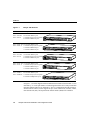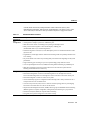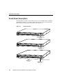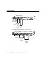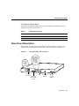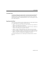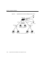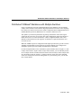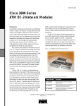
1
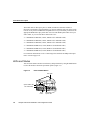
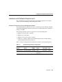
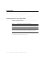
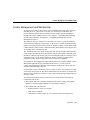
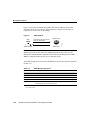
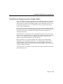
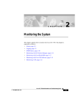
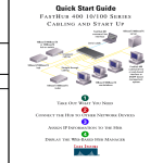
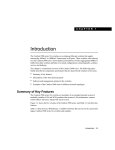
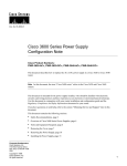
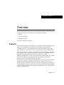
C H A PT E R
1
Overview
The following topics in this chapter describe the benefits and features of the Catalyst 1900
series Ethernet switches, also referred to as the Catalyst 1900 switches:
•
•
•
•
Features
Front and rear panels
Management options
Network configuration examples
Features
The Catalyst 1900 switches (shown in Figure 1-1) can improve network performance to the
desktop, server, and backbone, especially in networks that use high-performance
workstations and servers, use bandwidth-intensive applications, transfer large graphic,
audio, and video files, and require access to the same network resources and the Internet.
These switches have up to 25 10BaseT switched Ethernet ports (including the AUI switch
port on the back panel), each port providing users or groups of users dedicated 10-Mbps
bandwidth to resources within the network. These ports connect to other
10BaseT-compatible devices, such as single workstations and 10BaseT hubs. The switches
also have two 100BaseT switched ports for delivering maximum performance to
high-speed servers and to backbone switches and routers.
Each Catalyst 1900 switch is designed for plug-and-play operation, requiring only that you
assign basic IP information to the switch and connect it to the other devices in your
network. If you have specific network needs, you can also configure the switch through its
various management interfaces. The switch can be configured and monitored individually
or as part of a switch cluster that is managed by a Catalyst 2900 series XL or Catalyst 3500
series XL command switch.
Overview 1-1
Features
Catalyst 1900 Switches
Part Number
Description
WS–C1924–EN
WS–C1924–A
24 switched 10BaseT ports
1 switched AUI port (on rear panel)
2 switched 100BaseTX ports
WS–C1924C–EN 24 switched 10BaseT ports
WS–C1924C–A 1 switched AUI port (on rear panel)
1 switched 100BaseFX port
1 switched 100BaseTX port
WS–C1912–EN
WS–C1912–A
12 switched 10BaseT ports
1 switched AUI port (on rear panel)
2 switched 100BaseTX ports
WS–C1912C–EN 12 switched 10BaseT ports
WS–C1912C–A 1 switched AUI port (on rear panel)
1 switched 100BaseFX port
1 switched 100BaseTX port
SERIES
RPS
1x
2x
3x
4x
5x
6x
7x
8x
9x
10x
11x
12x
13x
14x
15x
16x
17x
18x
19x
20x
21x
22x
23x
24x
Ax
22x
23x
24x
A
Bx
MODE
SERIES
RPS
1x
2x
3x
4x
5x
6x
7x
8x
9x
10x
11x
12x
13x
14x
15x
16x
17x
18x
19x
20x
21x
Bx
MODE
10BaseT
RPS
1x
2x
3x
4x
5x
6x
SERIES
7x
8x
9x
10x
11x
12x
Ax
Bx
MODE
10BaseT
RPS
1x
2x
3x
4x
5x
6x
SERIES
7x
8x
9x
10x
11x
12x
A
MODE
WS–C1924F-A
24 switched 10BaseT ports
WS–C1924F-EN 1 switched AUI port (on rear panel)
2 switched 100-Mbps fiber ports
RPS
Bx
SERIES
1x
2x
3x
4x
5x
6x
7x
8x
MODE
9x
100BaseFX
10x
11x
12x
13x
14x
15x
16x
17x
18x
19x
20x
21x
22x
23x
24x
A
B
26602
Figure 1-1
In Figure 1-1, switches shipped with the standard software features (listed in Table 1-1) are
indicated by “-A” in the part number. Switches shipped with the Cisco Catalyst 1900/2820
Enterprise Edition Software are indicated by “-EN.” For information about the enterprise
edition software features (such as support for up to 1005 virtual LANs (VLANs); VLAN,
Inter-Switch Link (ISL), and Asynchronous Transfer Mode (ATM) LAN emulation
1-2
Catalyst 1900 Series Installation and Configuration Guide
Features
(LANE) trunk connections; ATM permanent virtual connections (PVCs); Fast
EtherChannel connections; and TACACS+ authentication), refer to the Catalyst 1900
Series and Catalyst 2820 Series Enterprise Edition Software Configuration Guide.
Table 1-1
Standard Software Features
Feature
Description
Performance
and
Configuration
• Half- and full-duplex operation on all 10- and 100-Mbps ports.
• Autonegotiation of duplex operation on 100BaseTX ports.
• IEEE 802.3x flow control on 100-Mbps ports operating in full-duplex mode.
• Back pressure-based congestion control on half-duplex, 10-Mbps ports
(standard IEEE 802.3 Layer 2 backoff algorithms).
• Enhanced Congestion Control (ECC) on all half-duplex ports for accelerated transmissions when
queues are full.
• FragmentFree (cut-through) and store-and-forward switching modes for optimal performance and
error checking.
• Per-port broadcast storm control for preventing faulty end stations from degrading overall system
performance.
• Support allowing ports to belong to up to four separate bridge groups within the switch.
• Cisco Group Management Protocol (CGMP) for limiting multicast flooding to predefined ports.
• IEEE 802.1d Spanning-Tree Protocol (STP) with Port Fast for network loop detection and
disabling and for fault-tolerant connectivity.
Management
• Catalyst 1900 Switch Manager for in-band management access through a web browser.
• Menu-based management console for in-band management access through Telnet sessions
and out-of-band management access through direct serial connection to the switch console port.
• Menu-based diagnostic console for switch recovery tasks.
• Cluster membership support for configuration and monitoring from a Catalyst 2900 series XL or
Catalyst 3500 series XL command switch.
• Cisco Discovery Protocol (CDP) versions 1 and 2 for network topology discovery and mapping
between the switch and other Cisco devices on the network.
• Simple Network Management Protocol (SNMP) and four groups of embedded remote monitoring
(RMON) agents for complete configuration, management, and monitoring on a per-port basis.
• Switch Port Analyzer (SPAN) for complete traffic monitoring.
• Encrypted (secret) password support for extra switch security.
Overview 1-3
Front-Panel Description
Front-Panel Description
The front panel of a Catalyst 1900 switch provides 12 or 24 10-Mbps and two 100-Mbps
switched ports (Figure 1-2) to connect to other network devices and a set of LEDs and a
Mode button for monitoring the switch and its ports (Figure 1-3).
Figure 1-2
RPS
Front-Panel Ports
SERIES
1x
2x
3x
4x
5x
6x
7x
8x
9x
100BaseFX
10x
11x
12x
13x
14x
15x
16x
17x
18x
19x
20x
21x
22x
23x
24x
A
B
MODE
100-Mbps fiber ports
(MT-RJ)
RPS
SERIES
1x
2x
3x
4x
5x
6x
7x
8x
9x
10x
11x
12x
13x
14x
15x
16x
17x
18x
19x
20x
21x
22x
23x
24x
Ax
Bx
MODE
26603
100BaseTX ports
(RJ-45)
RPS
SERIES
1x
2x
3x
4x
5x
6x
7x
8x
9x
10x
11x
12x
13x
14x
15x
16x
17x
18x
19x
20x
21x
22x
23x
24x
A
Bx
MODE
10BaseT ports
(RJ-45)
1-4
Catalyst 1900 Series Installation and Configuration Guide
100BaseTX port (RJ-45)
100BaseFX port
(duplex SC)
Switched 10-Mbps Ports
Switched 10-Mbps Ports
The 10BaseT network ports on the switch (1x through 12x or 1x through 24x) use standard
RJ-45 connectors. These ports can connect to 10BaseT-compatible devices, such as
individual workstations and hubs, with Category 3, 4, or 5 cabling. Using this type of
cabling, the distance between the switch and the attached device can be up to 100 meters.
For connection information, see the “Connecting to the Switched 10BaseT Ports” section
on page 2-23.
Switched 100-Mbps Ports
Depending on the model, the switch can have the following high-speed network ports:
•
•
•
Two switched 100BaseTX ports
One switched 100BaseTX port and one switched 100BaseFX port
Two switched 100-Mbps fiber-optic ports
The model with the 100BaseTX ports (Ax and Bx) use standard RJ-45 connectors. These
ports can connect to 100BaseTX-compatible servers, hubs, switches, and routers, with
Category 5 cabling. Using this type of cabling, the distance between the switch and the
attached device can be up to 100 meters. For connection information, see the “Connecting
to the Switched 100BaseTX Ports” section on page 2-25.
The model with one 100BaseFX port (A) uses a duplex square connector (SC). This port
can connect to other 100BaseFX-compatible devices with 50/125- or 62.5/125-micron
multimode fiber-optic cabling. For connection information, see the “Connecting to the
Switched 100BaseFX Port” section on page 2-27.
The fiber-optic connections between the switch and the attached device can be as follows:
•
If the switch port and the port on the attached device are configured for half-duplex
operation, the connection can be over distances of up to 412 meters.
•
If the switch port and the port on the attached device are configured for full-duplex
operation, the connection can be over distances of up to 2 kilometers.
Overview 1-5
Front-Panel Description
The model with two fiber-optic ports (A and B) use MT-RJ connectors and have a
fiber-optic wavelength of 1300 nanometers. To connect each fiber-optic port on the switch
to an SC or ST port on a 100BaseFX-compatible device on your network, you must use the
appropriate MT-RJ fiber-optic patch cable. You can order MT-RJ patch cables from your
cable vendor, or you can order these cables from Cisco:
•
•
•
•
•
•
CAB-MTRJ-SC-MM-1M (1-meter, MT-RJ-to-SC multimode cable)
CAB-MTRJ-SC-MM-3M (3-meter, MT-RJ-to-SC multimode cable)
CAB-MTRJ-SC-MM-5M (5-meter, MT-RJ-to-SC multimode cable)
CAB-MTRJ-ST-MM-1M (1-meter, MT-RJ-to-ST multimode cable)
CAB-MTRJ-ST-MM-3M (3-meter, MT-RJ-to-ST multimode cable)
CAB-MTRJ-ST-MM-5M (5-meter, MT-RJ-to-ST multimode cable)
For connection information, see the “Connecting to the Switched 100-Mbps Fiber-Optic
Ports” section on page 2-29.
LEDs and Modes
You can use the LEDs to monitor switch activity and performance by using the Mode button
to select the modes in which the port LEDs operate (Figure 1-3).
Figure 1-3
LEDs and Mode Button
Port LEDs
System status LED
1x
2x
3x
4x
H9261
26604
Port mode LEDs
Mode
button
1-6
Redundant power
system LED
Catalyst 1900 Series Installation and Configuration Guide
LEDs and Modes
System Status LED
The colors of the system status (SYSTEM) LED show that the switch is receiving power
and functioning properly (Table 1-2).
Table 1-2
SYSTEM LED Description
Color
System Status
Off
Switch is not powered up.
Solid green
Switch is operating normally.
Solid amber
Switch is receiving power, but might not be functioning properly. One or more
power-on self-test (POST) errors occurred. The Management Console Logon
Screen message identifies which nonfatal test(s) failed.
Note If a fatal error occurs, the switch is not operational, and no message is
displayed. (See the “Powering Up and Using POST to Test the Switch” section
on page 2-6 and the “Understanding POST Failures” section on page 5-7.)
Redundant Power Supply LED
The colors of the redundant power system (RPS) LED show the status (Table 1-3) of a
connected Cisco RPS (model PWR600-AC-RPS). For more information about the RPS, see
the “Power Connectors” section on page 1-12.
Table 1-3
RPS LED Description
Color
RPS Status
Off
RPS is off or is not installed.
Solid green
RPS is operational.
Blinking green
RPS and the switch AC power supply are both powered up.
Note This is not a recommended configuration. For more information, see the
“Power Connectors” section on page 1-12.
Solid amber
RPS is connected, but is not functioning properly. One of the power supplies in
the RPS could be powered down, or a fan in the RPS could have failed.
Overview 1-7
Front-Panel Description
Port LEDs and Modes
Each port has an LED above it. These LEDs, as a group or individually, display information
about the switch and about individual ports (Table 1-4).
Table 1-4
Port LED Modes Summary
Mode
LED
Determines...
Port status (default)
STAT
Status of individual ports
Bandwidth utilization
UTL
Percentage of the switch total bandwidth being used at any
one time
Full-duplex operation
FDUP
Which ports are operating in half- or full-duplex mode
Changing Between Modes
Pressing the Mode button on the front panel changes the mode of the port LEDs. The STAT,
UTL, and FDUP LEDs show which mode is active (Table 1-5). The selected mode remains
on approximately for 30 seconds before returning to the default mode (port status). You can
change the default mode from the Console Settings Menu.
Table 1-5
1-8
Changing Between Modes
For this Mode...
Push the Mode Button Until...
Port status
Only the STAT LED is on.
Bandwidth utilization
Only the UTL LED is on.
Full-duplex operation
Only the FDUP LED is on.
Catalyst 1900 Series Installation and Configuration Guide
LEDs and Modes
Port Status Mode
This is the factory default mode. The colors of the LEDs above the ports show the status of
the corresponding ports (Table 1-6).
Table 1-6
Port Status Mode LED Description
Color
Port Status
Off
No link.
Solid green
Link operational (with no link activity).
Flashing green
Link operational (with activity).
Alternating green
and amber
Link fault. Error frames can affect connectivity. Excessive collisions
and cyclic redundancy check (CRC), alignment, and jabber errors are
monitored for a link-fault indication.
Solid amber
Port is not forwarding. This could be because the port was disabled by
management, suspended because of an address violation, or suspended
by Spanning-Tree Protocol (STP) because of network loops.
Note The LEDs are solid amber for approximately 30 seconds after power up during
spanning-tree discovery.
Bandwidth Utilization Mode
In the UTL mode, the port LEDs as a group show the switch bandwidth being used at any
one time (see Figure 1-4 and Figure 1-5). The more LEDs that are lit, the higher the
bandwidth being used. The peak utilization is recorded in the bandwidth-capture interval,
described in the “Bandwidth Usage Report” section on page 4-81.
Overview 1-9
Front-Panel Description
Bandwidth Utilization Mode on a 12-Port Switch
10BaseT
RPS
1x
2x
3x
4x
5x
6x
7x
SERIES
8x
9x
10x
11x
26606
Figure 1-4
12x
A
Bx
MODE
From ports 1 to 4,
bandwidth is
bps to <1.5 Mbps.
From ports 5 to 8,
bandwidth is
1.5 Mbps to <20 Mbps.
From ports 9 to 12,
bandwidth is
20 Mbps to <140 Mbps.
Figure 1-5Bandwidth Utilization Mode on a 24-Port Switch
SERIES
1x
2x
3x
4x
5x
6x
7x
8x
9x
10x
11x
12x
13x
14x
15x
16x
17x
18x
19x
20x
21x
22x
23x
From
ports 1 to 8,
bandwidth is
0.1 Mbps to
<6 Mbps.
1-10
From
ports 9 to 16,
bandwidth is
6 Mbps to
<120 Mbps.
From
ports 17 to 24,
bandwidth is
120 Mbps to
<280 Mbps.
Catalyst 1900 Series Installation and Configuration Guide
24x
Ax
Bx
26607
RPS
MODE
Rear-Panel Description
Full-Duplex Operation Mode
The colors of the LEDs in FDUP mode show which 10BaseT and 100BaseT ports are
operating in full-duplex mode (Table 1-7).
Table 1-7
FDUP LED Description
Color
Full-Duplex
Off
Half-duplex mode is operational.
Solid green
Full-duplex mode is operational.
Rear-Panel Description
The rear panel of a Catalyst 1900 switch has an AC power connector, a console port, a
redundant power system (RPS) connector, and a switched AUI port (see Figure 1-6).
Figure 1-6
Rear-Panel Ports and Connectors
DC INPUT
FOR REMOTE
POWER SUPPLY
SPECIFIED
IN MANUAL.
+5V @6A
+12V @1A
26609
RATING
100-127V~
@0.6A
200-240V~
@0.3A
50-60Hz
RATING
100-127V~
@0.6A
200-240V~
@0.3A
50-60Hz
DC INPUT
FOR REMOTE
POWER SUPPLY
SPECIFIED
IN MANUAL.
+5V @6A
+12V @1A
AC power
connector
Redundant
power system
connector
CONSOLE
Fan
Console port
(RJ-45)
AUI
Ethernet
AUI port
(DB-15)
Overview 1-11
Rear-Panel Description
Power Connectors
Warning Attach only the Cisco RPS (model PWR600-AC-RPS) to the RPS connector.
You can provide power to the switch either by using the switch internal AC power supply
or by connecting the optional Cisco 600W AC Redundant Power System (RPS) to the RPS
connector on the switch.
The internal power supply is an autoranging unit that supports input voltages of 90 to
127 VAC or 200 to 250 VAC. To use the internal power supply, connect one end of the
supplied power cord to the AC power connector on the switch and the other end of the
power cord to an AC power outlet.
The RPS can provide a quasi-redundant power source for four external devices that use up
to 150W DC each. You can use a one-to-one cable (one connector at each cable end) to
connect four external devices to the four DC output power modules. The power source is
quasi-redundant because there are two AC input power modules for the RPS and one DC
output power module for each external device. The AC input to the RPS is fully redundant,
but the DC output to the external devices is not.
Note The Catalyst 1900 switches do not support the fully-redundant configurations that
are described in the Cisco RPS documentation. In addition, we recommend that you do not
use the redundant-with-reboot configuration with the switch connected to the RPS and to
the AC power plug, due to the reboot and downtime—approximately 30 seconds. If you do
use the redundant with reboot configuration, always power up the switch before you power
up the RPS to ensure correct operation. In circumstances where the RPS is first to power
up, the LEDs might not indicate the actual state.
For information about the RPS LED, see the “Redundant Power Supply LED” section on
page 1-7. For complete information about the RPS, refer to the Cisco RPS documentation.
1-12
Catalyst 1900 Series Installation and Configuration Guide
Console Port
Console Port
To configure and manage the switch through the menu-based management and diagnostic
consoles and the command-line interface (CLI), you can connect the console port to a
management station or modem with the supplied RJ-45-to-RJ-45 rollover console cable
and an appropriate adapter. For additional information, see the “Connecting to the Console
Port” section on page 2-16.
Switched AUI Port
You can connect the switched AUI port to an Ethernet transceiver, which is then connected
to a 10-Mbps Ethernet device through the following cable types:
•
10Base5—Thick coaxial cable connects the switch to another device up to a distance of
500 meters. This cable type uses F connectors.
•
10Base2—Thin coaxial cable connects the switch to another device up to a distance of
185 meters. This cable type uses T-type BNC connectors.
•
10BaseFL—Single- or multimode fiber-optic cable connects the switch to another
device up to a distance of 2 kilometers. This cable type uses S T or Bayonet connectors.
•
10BaseT—Unshielded twisted-pair cable connects the switch to another device over a
distance of 100 meters. This cable type uses standard RJ-45 connectors.
For connection information, see the “Connecting to the Switched AUI Port” section on
page 2-32.
Overview 1-13
Management Options
Management Options
You can use the default settings shipped with the Catalyst 1900 switch, or you can
customize the switch configuration through the management options described in this
section. The Catalyst 1900 Switch Manager is the easiest interface to use for basic
configuration and monitoring tasks. To perform all the configuration and monitoring tasks,
use the management console, the SNMP, or the command-line interface (CLI).
If your switch is or will be part of a switch cluster, you can also configure and monitor it
from the Cluster Management applications of a cluster command switch.
Access to the management console or CLI requires a direct connection to the switch
console port or a Telnet session. Access to the Catalyst 1900 Switch Manager, Cluster
Management applications, or SNMP requires a connection to one of the switch network
ports. For more information about accessing the management interfaces, see the “Accessing
the Management Interfaces” section on page 2-34.
This section describes the hardware and software requirements and provides the following
overviews:
•
•
•
•
•
Configuring the switch as an individual switch or as a cluster member
Catalyst 1900 Switch Manager, including the default settings
Management console, including the default settings
CLI
SNMP
Note The menu-based diagnostic console is described in the “Recovery Procedures Using
the Diagnostic Console” section on page 5-9.
1-14
Catalyst 1900 Series Installation and Configuration Guide
Hardware and Software Requirements
Hardware and Software Requirements
This section describes the requirements and recommended configurations for using the
Catalyst 1900 Switch Manager and the management console.
Hardware Requirements for the Management Station
The minimum hardware requirement for a PC is a Pentium processor running at 166 MHz
with 64 MB of DRAM. The minimum requirement for a UNIX workstation is a Sun Ultra 1
running at 143 MHz.
The following operating systems are supported for web-based management:
•
•
•
•
Windows 95 (Service Pack 1 required)
Windows 98, second edition
Windows NT 4.0 (Service Pack 3 required)
Solaris 2.5.1 or higher, with the Sun-recommended patch cluster for that operating
system and Motif library patch 103461-24
Table 1-8 lists the configurations that yield the best results for web-based management:
Table 1-8
Recommended Platform Configurations
Operating
System
Processor
Speed
DRAM
Number of
Colors
Resolution
Font
Size
Windows NT 4.0
Pentium 300 MHZ
128 MB
65536
1024 x768
Small
SunOS 5.6
Sparc 333 MHz
128 MB
Most colors for
applications
—
Small (3)
Overview 1-15
Management Options
Software Requirements for Using the Management Console
To use the management console, you must have terminal emulation software (such as
ProComm, HyperTerminal, tip, or minicom) installed on your management station.
Software Requirements for Using the Switch Manager
To use the Catalyst 1900 Switch Manager, you must have one of these web browsers
installed on your management station:
Table 1-9
Browser Support for Web-based Management
Browser
Minimum Version
Supported Versions
Netscape Communicator
4.5
4.5, 4.51, 4.61
Microsoft Internet Explorer
4.01a
4.01a, 5.0
Note Netscape Communicator 4.60 is not a supported browser. Microsoft Internet
Explorer is not a supported browser on Solaris 2.5.1 or higher operating systems.
For information about how to configure your browser for web-based management, see the
“Accessing the Switch Manager” section on page 2-34.
1-16
Catalyst 1900 Series Installation and Configuration Guide
Cluster Management and Membership
Cluster Management and Membership
As with previous Catalyst 1900 releases, you can configure and monitor the switch as an
individual device in your network. To do this, you must assign it an IP address and
password and then use the options available from the Catalyst 1900 Switch Manager,
management console, SNMP, or the CLI. (See Chapter 3, “Configuring and Monitoring
from the Switch Manager,” and Chapter 4, “Configuring and Monitoring from the
Management Console.”)
The switch can also be a member of a switch cluster. A cluster is a group of connected
switches that are managed as a single entity. A cluster has a command switch and member
switches. The Catalyst 1900 switches can only be member switches. Certain models of the
Catalyst 2900 XL switches can be command switches, and all models of the Catalyst 3500
XL switches can be command switches.
The command switch is the central management point used to configure and monitor the
switch cluster. All communication with member switches is through the command switch
IP address. Clustering can simplify your network management tasks. For example, from a
command switch, you can manage and monitor member switches regardless of their
geographic location, and you can perform cluster-wide firmware upgrades.
Not all Catalyst 1900 configuration and monitoring options are available from the Cluster
Management applications of the command switch; however, you can access the
Catalyst 1900 management interfaces (switch manager, management console, and CLI)
from the command switch at any time.
Each switch in a cluster can belong to only one cluster at a time. The switches in a cluster
can be in the same location, or they can be distributed across a network. The Catalyst 1900
switches can be connected to a cluster in a star or daisy-chain topology through copper or
fiber-optic cables.
To configure and monitor a Catalyst 1900 switch as a cluster member, the following
requirements must be met:
•
The Catalyst 2900 XL or 3500 XL command switch must be running IOS Software
Release 12.0(5)XP or higher and must have an IP address assigned.
•
The Catalyst 1900 switch must be
— Running firmware version 9.x or higher.
— CDP version 2-enabled.
— Connected to a cluster-member or to a command-switch port assigned to the
Overview 1-17
Management Options
management VLAN.
1-18
Catalyst 1900 Series Installation and Configuration Guide
Cluster Management and Membership
When the Catalyst 1900 switch joins a cluster, the following configuration settings change:
•
The highest privileged-level password (encrypted or unencrypted) of the command
switch becomes the password to the Catalyst 1900 Switch Manager, management
console, and CLI. If the command switch does not have a password, then no password
is required when accessing the Catalyst 1900 switch from the command switch. (See the
“Changing the Switch Password” section on page 3-8 or the “Console Settings Menu”
section on page 4-6.)
•
The host name you assign to the Catalyst 1900 switch is kept even when the switch joins
or leaves a cluster. If the Catalyst 1900 switch does not have a name when it joins a
cluster, the command switch assigns it a name. (See the “Switch Host Name” section on
page 3-6 and the “System Configuration Menu” section on page 4-11.)
•
The command switch propagates its first SNMP Read and Write community strings as
the last Read and Write community strings for the member switch. If the joining
Catalyst 1900 switch already has four Read and four Write community strings, the
command switch overrides the fourth community strings with its own first community
strings. When the switch leaves the cluster, the command-switch community strings are
deleted.
Each string from the command switch contains up to 27 characters and a suffix
“@esNN” where NN is the member switch number. (See the “Changing the SNMP
Settings” section on page 3-35 or the “Network Management (SNMP) Configuration
Menu” section on page 4-24.)
Caution Do not use “@es” in the community strings you define for the switch. When the
switch joins a cluster, any community string containing “@es” is deleted.
For complete information about cluster management and membership, refer to the
Cisco IOS Desktop Switch Software Configuration Guide, Catalyst 2900 Series XL and
Catalyst 3500 Series XL Cisco IOS Release 12.0(5)XP.
Overview 1-19
Management Options
Catalyst 1900 Switch Manager
The Catalyst 1900 Switch Manager (hereafter referred to as the switch manager) is a
web-based, graphical user interface for basic switch configuration and monitoring. Using
the switch manager, you can configure and monitor the switch from anywhere on your
intranet.
Each switch manager page
•
•
•
Provides fields, check boxes, and lists for individual configuration settings.
Displays current information about the switch.
Provides online help for each page:
— Detailed information about the fields, lists, check boxes, and buttons.
— Specific procedures for performing management tasks.
Note For supported and recommended hardware and software requirements, see the
“Hardware and Software Requirements” section on page 1-15.
For information about using the switch manager, see Chapter 3, “Configuring and
Monitoring from the Switch Manager.”
Table 1-10 lists the configuration settings, including default values, available from the
switch manager.
1-20
Catalyst 1900 Series Installation and Configuration Guide
Catalyst 1900 Switch Manager
Table 1-10
Features, Default Settings, and Switch Manager Pages
Feature
Default Setting
Switch Manager Page
IP address, subnet mask, and default gateway
of the switch
0.0.0.0
System Management Page
Cisco Discovery Protocol (CDP)
Enabled
CDP Management Page
Switching mode
FragmentFree
(cut-through)
System Management Page
Enhanced congestion control on 10BaseT ports
Disabled
System Management Page
Enhanced congestion control on 100BaseT ports
Disabled
Port Management Page
Duplex mode on 10BaseT ports
Half duplex
Port Management Page
Half-duplex back pressure on 10BaseT ports
Disabled
System Management Page
Duplex mode on switched 100BaseFX ports
Half duplex
Port Management Page
Duplex mode on switched 100BaseTX port
Autonegotiate
Port Management Page
Broadcast storm control
Disabled
System Management Page
Store-and-forward on multicast
Disabled
System Management Page
Network port
None
System Management Page
Cisco Group Management Protocol (CGMP)
Enabled
CGMP Management Page
Flooding unknown unicast packets
Enabled
Port Management Page
Flooding unregistered multicast packets
Enabled
Port Management Page
Management
Performance Tuning
Flooding/Traffic Control
Overview 1-21
Management Options
Table 1-10
Features, Default Settings, and Switch Manager Pages (continued)
Feature
Default Setting
Switch Manager Page
Spanning-Tree Protocol (STP)
Enabled
Spanning-Tree Management Page
Port Fast mode on 10BaseT ports
Enabled
Spanning-Tree Management Page
Port Fast mode on 100BaseT ports
Disabled
Spanning-Tree Management Page
Port monitoring (SPAN)
Disabled
SPAN Configuration Page
Remote monitoring (RMON)
Enabled
—
Usage reports
—
Detailed Port Statistics Page
Statistics Reports Page
Password
None
Home Page
Action on address violation
Suspend
System Management Page
Address security
Disabled
Address Table Management Page
Port Security Table Page
Trap managers
None
SNMP Management Page
Write (read/write) managers
None
SNMP Management Page
Community strings
Public/Private
SNMP Management Page
—
Console and Upgrade Configuration
Page
Network Redundancy/Fault Tolerance
Diagnostics
Security
Upgrades
Firmware
For procedures on how to reset all switch settings to the factory defaults, see the “System
Configuration Menu” section on page 4-11 or the “Resetting the Switch to the Factory
Defaults” section on page 5-18.
1-22
Catalyst 1900 Series Installation and Configuration Guide
Management Console
Management Console
The management console is a menu-driven interface for configuring and monitoring the
switch. If your management station is directly connected to the switch console port, you
can use the management console even when the network is down because your direct
connection to the console bypasses the network and communicates directly with the switch.
For information about using the management console, see Chapter 4, “Configuring and
Monitoring from the Management Console.”
Table 1-11 lists the configuration settings, including default values, available from the
management console.
Table 1-11
Features, Default Settings, and Management Console Menus
Default
Setting
Console Menu
IP address, subnet mask, and default gateway
of the switch
0.0.0.0
IP Configuration Menu
Cisco Discovery Protocol (CDP)
Enabled
CDP Configuration/Status Menu
Switching mode
FragmentFree
(cut-through)
System Configuration Menu
Enhanced congestion control on 10BaseT ports
Disabled
System Configuration Menu
Enhanced congestion control on 100BaseT ports
Disabled
Port Configuration Menu (100BaseT Ports)
Duplex mode on 10BaseT ports
Half duplex
Port Configuration Menu (10BaseT Ports)
Half-duplex back pressure on 10BaseT ports
Disabled
System Configuration Menu
Duplex mode on 100BaseFX port
Half duplex
Port Configuration Menu (100BaseT Ports)
Duplex mode on 100BaseTX ports
Autonegotiate
Port Configuration Menu (100BaseT Ports)
Broadcast storm control
Disabled
System Configuration Menu
Network port
None
System Configuration Menu
Cisco Group Management Protocol (CGMP)
Enabled
Cisco Group Management Protocol (CGMP)
Configuration Menu
Overlapping bridge groups
Disabled
Bridge Group Configuration Menu
Store-and-forward on multicast
Disabled
System Configuration Menu
Feature
Management
Performance Tuning
Flooding/Traffic Control
Overview 1-23
Management Options
Table 1-11
Features, Default Settings, and Management Console Menus (continued)
Default
Setting
Console Menu
Flooding unknown unicast packets
Enabled
Port Addressing Menu
Flooding unregistered multicast packets
Enabled
Port Addressing Menu
Feature
Network Redundancy/Fault Tolerance
Spanning-Tree Protocol (STP)
Enabled
Spanning Tree Configuration Menu
Port Fast mode on 10BaseT ports
Enabled
Port Configuration Menu (10BaseT Ports)
Port Fast mode on 100BaseT ports
Disabled
Port Configuration Menu (100BaseT Ports)
Port monitoring (SPAN)
Disabled
Monitoring Configuration Menu
Remote monitoring (RMON)
Enabled
—
Usage reports
—
Port Status Report
Port Addressing Report
Exception Statistics Report
Utilization Statistics Report
Bandwidth Usage Report
None
Console Settings Menu
Diagnostics
Security
Password
Action on address violation
Suspend
System Configuration Menu
Address security
Disabled
Port Addressing Menu
Trap managers
None
Network Management (SNMP) TRAP
Configuration Menu
Write (read/write) managers
None
Network Management (SNMP) WRITE
Configuration Menu
Community strings
Public/Private
Network Management (SNMP) READ
Configuration Menu
Network Management (SNMP) WRITE
Configuration Menu
—
Firmware Configuration Menu
Upgrading
Firmware
For procedures on how to reset all switch settings to the factory defaults, see the “System
Configuration Menu” section on page 4-11 or the “Resetting the Switch to the Factory
Defaults” section on page 5-18.
1-24
Catalyst 1900 Series Installation and Configuration Guide
Command-Line Interface
Command-Line Interface
For switches shipped or upgraded with the Cisco Catalyst 1900/2820 Enterprise Edition
Software, you can use the command-line interface (CLI) to access the configuration options
and perform the same configuration and monitoring tasks available through the
Catalyst 1900 Switch Manager and management console. You can also perform privileged
configuration and monitoring tasks available only through the CLI and SNMP.
For complete information about the CLI, refer to the online-only Catalyst 1900 Series and
Catalyst 2820 Series Command Reference.
Simple Network Management Protocol
You can configure and monitor the switch by accessing the Management Information Base
(MIB) variables through Simple Network Management Protocol (SNMP), an
application-layer protocol designed to facilitate the exchange of management information
between network devices. The switch supports a comprehensive set of MIB objects,
including four Remote Monitoring (RMON) groups.
The SNMP system consists of three parts: SNMP manager, SNMP agent, and the MIB files.
SNMP places all operations in a get-request, get-next-request, and set-request format. For
example, an SNMP manager can get a value from an SNMP agent or store a value into that
SNMP agent. The SNMP manager can be part of a network management system (NMS),
and the SNMP agent can reside on a networking device such as a switch. You can compile
the switch MIB files with your network management software. The SNMP agent can
respond to MIB-related queries being sent by the NMS.
An example of an NMS is the CiscoWorks network management software. CiscoWorks
uses the switch MIB variables to set device variables and to poll devices on the network for
specific information. The results of a poll can be displayed as a graph and analyzed in order
to troubleshoot internetworking problems, increase network performance, verify the
configuration of devices, monitor traffic loads, and more.
Overview 1-25
Management Options
Figure 1-7 shows how the SNMP agent gathers data from the MIB file, which holds
information about device parameters and network data. The agent can send traps, or
notification of certain events, to the manager.
NMS
SNMP Network
Get-request, Get-next-request,
Get-bulk, Set-request
Get-response, traps
SNMP Manager
Network device
MIB
SNMP Agent
S1203a
Figure 1-7
Note Make sure you use the correct Read and Write community strings so that your
SNMP request does not fail. Refer to the SNMP Management Page or the Network
Management (SNMP) READ Configuration Menu and Network Management (SNMP)
WRITE Configuration Menu for the correct community strings.
The SNMP manager uses information in the MIB files to perform the operations described
in Table 1-12.
Table 1-12
Operation
Description
get-request
Retrieves a value from a specific variable.
get-next-request
Retrieves a value from a variable within a table.1
get-response
Reply to a get-request, get-next-request, and set-request sent by an NMS.
set-request
Store a value in a specific variable.
trap
Send an unsolicited message from an SNMP agent to an SNMP manager
indicating that some event has occurred.
1
1-26
SNMP Manager Operations
An SNMP manager does not need the exact variable name. It sequentially searches to find the needed variable
from within a table.
Catalyst 1900 Series Installation and Configuration Guide
Simple Network Management Protocol
Remote Monitoring
The Remote Monitoring (RMON) MIB is used by network managers to monitor remote
devices. An RMON implementation consists of a software probe that continually collects
statistics about a LAN and a management station that communicates with the probe. The
probe transfers information to the management station on request or when a predefined
threshold is crossed. You can use the statistics to help tune or troubleshoot your switched
LAN.
RMON is enabled by default on the switches and is not displayed on the Catalyst 1900
Switch Manager or management console. The switch supports four RMON groups
(Table 1-13) as defined in RFC 1757. You can obtain information about the four supported
groups by using any SNMP management application.
Table 1-13
RMON Groups and Their Functions
Group Name
Description
Statistics
This group collects utilization and error statistics for the monitored switch. Statistics include
information about collisions, cyclic redundancy checks (CRCs) and alignment; undersized or
oversized packets, jabber, fragments, broadcast, multicast, and unicast messages; and bandwidth
utilization. For example, you could use this group to determine how many error packets have
been seen on a given port.
Statistics from this group can be used by the history group to record historical views of network
performance. A statistics row is established by default for each switch port.
History
This group takes periodic samples from the statistics section and stores them for later retrieval.
This sampling includes information such as utilization, error counts, and packet counts. This
information can be used to establish baseline information regarding network activity. You can
define the intervals you want to record information for, and you can define how many of the
samples are to be stored.
Note RMON statistics gathering has a maximum limit of 540 history tables that can be allocated
among all switch ports.
Alarm
This group generates alarms according to user-defined thresholds. You could, for example,
configure RMON to generate an alarm when alignment errors on a port exceeded a predefined
limit. Rising and falling thresholds can be defined, and the events group can generate traps and
automated responses based on the alarms.
Event
This group sends traps (events) to the management station based on information (alarms)
received from the alarm group. The time and date are recorded with each logged event. You can
use the events group to create customized reports that are based on alarm types.
Overview 1-27
Network Configuration Examples
Network Configuration Examples
As your network users compete for network bandwidth, it takes longer to send and receive
data. Network performance can degrade for reasons such as:
•
•
•
•
•
Too many users on a single network segment
High demand from networked applications, such as e-mail with large attached files
High demand from bandwidth intensive applications, such as multimedia
A growing number of users accessing the Internet
The increased power of new PCs, workstations, and servers
You can design your network to increase the bandwidth available to your network users by
using one or more of the following methods:
•
Create smaller network segments so that fewer users share the bandwidth, and place the
network resources in the same logical network as the users who access those resources
most.
•
Connect power users and global resources (such as servers and routers), which require
equal access by network users, directly to the switch ports or to other Fast Ethernet hubs
and switches. Global resources should be placed in their own Fast Ethernet segment.
•
Use full-duplex operation between the switch and its connected devices.
This section provides network configuration examples for using the Catalyst 1900 switches
in your network to create dedicated network segments and interconnecting the segments
through its high-speed ports:
•
•
•
•
•
1-28
Client/server workgroup with a single switch
Distributed 100BaseT backbone with multiple switches
100BaseT collapsed backbone with multiple switches
100BaseT redundant backbone with multiple switches
Extended network with multiple switches
Catalyst 1900 Series Installation and Configuration Guide
Client/Server Workgroup with a Single Switch
Client/Server Workgroup with a Single Switch
Figure 1-8 illustrates a standard configuration in which bandwidth is shared by all attached
devices. The nodes (workstations, hubs, and servers) in the workgroup are divided into
smaller groups to increase the bandwidth available to each of them and to improve server
response time. Grouping servers in a centralized location can provide benefits such as
security and easier maintenance.
Network resources (such as web and mail servers) are connected to the 100BaseT ports on
the Catalyst 1900 switch, allowing 100-Mbps throughput to users when needed. When the
switch and server ports are configured for full-duplex operation, the links provide
200 Mbps of bandwidth.
Bandwidth-intensive workstations, such as computer-aided design (CAD) users or other
power users, are connected to the switch 10BaseT ports for their own 10-Mbps bandwidth
access to servers. Single workstations, configured for full-duplex operation, receive
20 Mbps of dedicated bandwidth from each switched port.
Other workstations are connected to 10BaseT hubs, which provide 10-Mbps shared
bandwidth to users with multiple workstations or to workgroups that require minimal
network bandwidth. These workstations share the available 10-Mbps of bandwidth
available from the switched link. Because hubs run only in half-duplex, each connected port
provides 10 Mbps of bandwidth.
Connecting a router to a 100BaseT switch port provides multiple, simultaneous links to the
Internet through one line.
Overview 1-29
Network Configuration Examples
Figure 1-8
High-Performance Client/Server Workgroup with a Switch
Catalyst 1900
100 Mbps
(200 Mbps full duplex)
10 Mbps
10 Mbps
(20 Mbps
full duplex)
10 Mbps
10BaseT hub
100BaseT servers
10BaseT hub
10BaseT hub-attached workstations
1-30
Catalyst 1900 Series Installation and Configuration Guide
S6294
Single workstations
Distributed 100BaseT Backbone with Multiple Switches
Distributed 100BaseT Backbone with Multiple Switches
Figure 1-9 illustrates a network configuration that uses the 100BaseT ports on multiple
Catalyst 1900 switches to interconnect workgroups and network resources. All workgroups
have full access to the network resources (such as a Dynamic Host Configuration Protocol
(DHCP)/Bootstrap Protocol (BOOTP) server or an IPTV multicast server).
You optimize your network performance by placing workstations on the same logical
segment as the servers they access most often. This configuration reduces the amount of
traffic that travels over a network backbone, which is a high-bandwidth (such as Fast
Ethernet) connection between the segments. A backbone is required if numerous users
access the servers.
When the 100BaseT ports are configured for full-duplex operation, they provide a total of
200 Mbps of bandwidth on each switch port. Switched 10BaseT ports configured for
full-duplex operation provide 20 Mbps of bandwidth to workstations.
For increased performance to the workstations, replace the hubs shown in Figure 1-9 with
Catalyst 1900 switches. In place of the Catalyst 1900 switches, you can add Catalyst 2900
XL or Catalyst 3500 XL switches and form a switch cluster of Catalyst 1900, Catalyst 2900
XL, and Catalyst 3500 XL switches. A Catalyst 3500 XL switch can be the command
switch, the central point of network management. As your network grows, you can add
more switch clusters.
Overview 1-31
Network Configuration Examples
Figure 1-9
Distributed 100BaseT Backbone with Multiple Switches
Catalyst 1900
member switch
10BaseT hub
10 Mbps
100 Mbps
(200 Mbps full duplex)
100BaseT
server
10 Mbps
(20 Mbps full duplex)
10BaseT hub-attached
workstations
100 Mbps
(200 Mbps full duplex)
Single workstations
Catalyst 1900
member switch
10BaseT hub
10 Mbps
10 Mbps
(20 Mbps full duplex)
100 Mbps
(200 Mbps full duplex)
10BaseT hub-attached
workstations
Single workstations
Catalyst 3500 XL
command switch
FastHub
400 series
100 Mbps
(200 Mbps full duplex)
10/100 Mbps
10/100 Mbps
10BaseT/
100BaseT
single workstations
Daisy-chained
Catalyst 2900 XL,
Catalyst 2820,
and Catalyst 1900
member switches
29171
10BaseT/
100BaseT
hub-attached
workstations
100BaseT
server
1-32
Catalyst 1900 Series Installation and Configuration Guide
100BaseT Collapsed Backbone with Multiple Switches
100BaseT Collapsed Backbone with Multiple Switches
Figure 1-10 illustrates a Fast Ethernet collapsed-backbone configuration in which all
segments and subnetworks are connected to a single device, such as a hub, switch, or router,
to form the enterprise internetwork. A collapsed backbone network is easy to manage and
troubleshoot, as it provides a single point for monitoring and controlling the network.
Two different workgroups, perhaps located in different buildings, are connected by
Catalyst 1900 switches connected to a 100BaseT backbone switch or router (such as a
Catalyst 5000 switch or Cisco 7000 router). In full-duplex mode, 200 Mbps of bandwidth
is available to both Catalyst 1900 switches.
The distance between each Catalyst 1900 switch and the backbone switch or router can be
increased to 2 kilometers by using fiber-optic ports in full-duplex mode. The Catalyst 1900
models—WS-C1924C, WS-C1912C, and WS-C1924F—provide one duplex SC port or
two fiber-optic MT-RJ ports. Connections through the 100BaseTX switch ports with
Category 5 cabling can be up to a distance of 100 meters.
Overview 1-33
Network Configuration Examples
Figure 1-10
100BaseT Collapsed Backbone with Multiple Switches
Catalyst 5000 series
or Cisco 7000 series
100 Mbps
(200 Mbps full duplex)
Catalyst 1900
10 Mbps
100 Mbps
(200 Mbps full duplex)
100BaseT server
100 Mbps
Catalyst 1900
100 Mbps
(200 Mbps
full duplex)
(200 Mbps full duplex)
100BaseT server
10 Mbps
(20 Mbps full duplex)
10 Mbps
10BaseT
hub
10BaseT
hub
S6297
Single workstations
10BaseT hub-attached workstations
1-34
Catalyst 1900 Series Installation and Configuration Guide
100BaseT Redundant Backbone with Multiple Switches
100BaseT Redundant Backbone with Multiple Switches
Figure 1-11 illustrates how network redundancy provides two advantages:
•
•
A backup path, in the event of a failure in the network
Load-balancing, when two or more paths to a destination exist and both can be used,
depending on the network load
A 100-Mbps (200 Mbps in full-duplex) redundant backbone is created by connecting
Catalyst 1900 switches to 100BaseT backbone switches or routers, such as Catalyst 5000
switches or Cisco 7000 routers. Each Catalyst 1900 switch connects to the two backbone
devices, shown in the top-left and top-right corners, in a redundant configuration. If
connectivity is lost to one of the backbone routers or switches, the network uses the
redundant connection.
Spanning-Tree Protocol, available only on switches, ensures that only one of the two
connections from each switch is active (the primary link), ensuring that there are no loops
in the network paths. If the primary link fails, the secondary link becomes active.
Overview 1-35
Network Configuration Examples
Figure 1-11
100BaseT Redundant Backbone with Multiple Switches
Catalyst 5000 series
or Cisco 7000 series
Catalyst 5000 series
or Cisco 7000 series
100 Mbps
(200 Mbps full duplex)
Catalyst 1900
100 Mbps
(200 Mbps full duplex)
10 Mbps
10BaseT
hub
10BaseT hub-attached workstations
10 Mbps
(20 Mbps full duplex)
Single workstation
Catalyst 1900
100 Mbps
(200 Mbps full duplex)
10 Mbps
(20 Mbps
full duplex)
100 Mbps
(200 Mbps full duplex)
Single workstations
Catalyst 1900
10 Mbps
10BaseT
hub
10BaseT hub-attached workstations
1-36
Catalyst 1900 Series Installation and Configuration Guide
100 Mbps
(200 Mbps full duplex)
10 Mbps
(20 Mbps full duplex)
Single workstation
S6298
100 Mbps
(200 Mbps full duplex)
Extended Network with Multiple Switches
Extended Network with Multiple Switches
A system of routers, switches, and hubs can be combined to create a high-performance
network that extends beyond the main office LAN to connect to branch offices, remote sites,
mobile users, and the Internet. Figure 1-12 is an example of an extended network.
Figure 1-12
Extended Network with Multiple Switches
Branch office
Internet
Cisco 1600 or
2500 series
Catalyst 1900
series
Main office
100BaseT
server
Catalyst 1900 series
Cisco 3600
series
Single workstations
FastHub
400 series
Single workstations
Cisco 700 series
CiscoRemote
S6293
100BaseT hub-attached
workstations and servers
Remote sites and mobile users
Overview 1-37
Network Configuration Examples
1-38
Catalyst 1900 Series Installation and Configuration Guide