1
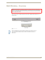
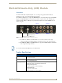
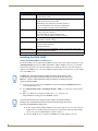
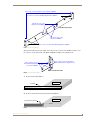
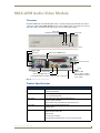
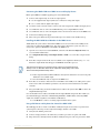
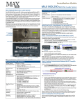
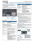
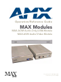
Operation/Reference Guide
MAX Modules
MAX-AOM Audio-Only (USB) Module
MAX-AVM Audio/Video Module
Document ID: 065-004-2963
Last Revised: 6/11/2006
AMX Limited Warranty and Disclaimer
AMX warrants its products to be free of defects in material and workmanship under normal use for three (3) years from
the date of purchase from AMX, with the following exceptions:
•
Electroluminescent and LCD Control Panels are warranted for three (3) years, except for the display and touch
overlay components that are warranted for a period of one (1) year.
•
Disk drive mechanisms, pan/tilt heads, power supplies, and MX Series products are warranted for a period of one
(1) year.
•
AMX Lighting products are guaranteed to switch on and off any load that is properly connected to our lighting
products, as long as the AMX Lighting products are under warranty. AMX does guarantee the control of dimmable
loads that are properly connected to our lighting products. The dimming performance or quality cannot be
guaranteed due to the random combinations of dimmers, lamps and ballasts or transformers.
•
Unless otherwise specified, OEM and custom products are warranted for a period of one (1) year.
•
AMX Software is warranted for a period of ninety (90) days.
•
Batteries and incandescent lamps are not covered under the warranty.
This warranty extends only to products purchased directly from AMX or an Authorized AMX Dealer.
All products returned to AMX require a Return Material Authorization (RMA) number. The RMA number is obtained
from the AMX RMA Department. The RMA number must be clearly marked on the outside of each box. The RMA is
valid for a 30-day period. After the 30-day period the RMA will be cancelled. Any shipments received not consistent
with the RMA, or after the RMA is cancelled, will be refused. AMX is not responsible for products returned without a
valid RMA number.
AMX is not liable for any damages caused by its products or for the failure of its products to perform. This includes any
lost profits, lost savings, incidental damages, or consequential damages. AMX is not liable for any claim made by a
third party or by an AMX Dealer for a third party.
This limitation of liability applies whether damages are sought, or a claim is made, under this warranty or as a tort claim
(including negligence and strict product liability), a contract claim, or any other claim. This limitation of liability cannot
be waived or amended by any person. This limitation of liability will be effective even if AMX or an authorized
representative of AMX has been advised of the possibility of any such damages. This limitation of liability, however, will
not apply to claims for personal injury.
Some states do not allow a limitation of how long an implied warranty last. Some states do not allow the limitation or
exclusion of incidental or consequential damages for consumer products. In such states, the limitation or exclusion of
the Limited Warranty may not apply. This Limited Warranty gives the owner specific legal rights. The owner may also
have other rights that vary from state to state. The owner is advised to consult applicable state laws for full
determination of rights.
EXCEPT AS EXPRESSLY SET FORTH IN THIS WARRANTY, AMX MAKES NO OTHER WARRANTIES,
EXPRESSED OR IMPLIED, INCLUDING ANY IMPLIED WARRANTIES OF MERCHANTABILITY OR FITNESS FOR
A PARTICULAR PURPOSE. AMX EXPRESSLY DISCLAIMS ALL WARRANTIES NOT STATED IN THIS LIMITED
WARRANTY. ANY IMPLIED WARRANTIES THAT MAY BE IMPOSED BY LAW ARE LIMITED TO THE TERMS OF
THIS LIMITED WARRANTY.
Table of Contents
Table of Contents
MAX Modules - Overview ...................................................................................1
MAX-AOM Audio-Only (USB) Module ................................................................3
Overview .................................................................................................................. 3
Product Specifications ............................................................................................. 4
Installing the MAX-AOM........................................................................................... 4
Adding the MAX-AOM to the MMS Server..................................................................... 4
Connecting the MAX-AOM to the MMS Server .............................................................. 6
Additional Information on USB Ports 1 and 2
(on the MMS-04S, MMS-12S and MMS-900 Servers) ................................................... 6
Rack-Mounting the MAX-AOM........................................................................................ 6
Using the AOM-EX Expansion Kit ................................................................................... 7
MAX-AVM Audio-Video Module .......................................................................11
Overview ................................................................................................................ 11
Product Specifications................................................................................................... 12
Installing the MAX-AVM ......................................................................................... 12
Connecting the MAX-AVM to an MMS Server and Display Device ............................... 13
Installing the MAX-AVM Serial Number In the MMS Server.......................................... 13
Using a PC Mouse and Keyboard to Control the MAX-AVM......................................... 14
Troubleshooting ............................................................................................................ 14
MAX-AVM User-Interface .................................................................................15
Overview ................................................................................................................ 15
Start Screen ............................................................................................................ 15
MUSIC Pages .......................................................................................................... 15
MUSIC - GENRE............................................................................................................. 16
MUSIC - ARTIST............................................................................................................. 16
MUSIC - SEARCH........................................................................................................... 16
MUSIC - BROWSE.......................................................................................................... 16
Music Selections............................................................................................................ 17
Music Playback Page ..................................................................................................... 18
MOVIES Pages ........................................................................................................ 18
MOVIES - GENRE .......................................................................................................... 18
MOVIES - SEARCH ........................................................................................................ 19
MOVIES - BROWSE ....................................................................................................... 19
Movie Selections and Transport Controls...................................................................... 19
Movie Playback Page .................................................................................................... 20
Parental Control ............................................................................................................ 20
PLAYLISTS Page...................................................................................................... 21
MAX AOM and AVM Modules
i
Table of Contents
WinMAX Software .................................................................................................. 22
ii
MAX AOM and AVM Modules
MAX Modules - Overview
MAX Modules - Overview
NOTICE: MAX Products are not designed or intended to, and may not be used to, violate anyone’s
copyright or other intellectual property rights. Each user of the Products may only use the Products in
connection with materials legally owned or licensed by such user and only to the extent such ownership
or license rights permit such use.
This document describes the MAX-AOM (Audio-Only USB), and MAX-AVM (Audio/Video) and
Modules (FIG. 1).
MAX-AOM Audio-Only (USB) Module
(FG 2178-55)
MAX-AVM Audio-Video Module
(FG 2178-50)
FIG. 1 MAX Modules
Refer to the MAX Servers Instruction Manual (available online at www.amx.com), as
well as the individual Installation Guides for details and installation instruction on
MAX Servers.
MAX AOM and AVM Modules
1
MAX Modules - Overview
2
MAX AOM and AVM Modules
MAX-AOM Audio-Only (USB) Module
MAX-AOM Audio-Only (USB) Module
Overview
The MAX-AOM Audio-Only Module (FIG. 2) is a streaming audio playback USB module that
distributes up to four stereo outputs (both digital and analog).
The AOM is available either as a single unit (FG 2178-55), or as two units using the optional AOM-EX
Expansion Kit (FG 2178-56) that mount side-by-side within a single rack unit. The AOM-EX adds
another four audio outputs, to allow up to eight audio-only outputs. Note that the AOM-EX does not
include a faceplate.
OUTPUT 1
OUTPUT 2
OUTPUT 3
OUTPUT 4
(rear)
Power Connector
USB connector (to MMS server)
FIG. 2 MAX-AOM Audio-Only Module - rear panel connectors
The MMS-01S, MMS-02S and MMS-02SB servers feature two built-in audio output
channels, and support one MAX-AOM (for a maximum total of six audio output channels).
The MMS-04S, MMS-12S and MMS-900 servers support two MAX-AOMs (for a maximum
total of eight audio output channels).
Do not use a USB hub with MMS servers or AOM modules.
Product Specifications
MAX-AOM (FG 2178-55) Specifications
Power:
• 5VDC 0.9A external power supply
• 110-240 VAC 50/60 Hz
AC Current Draw (AMP):
• .09A - Bootup/Power Cycle Peak
• .09A - Normal Usage Peak
Audio Output:
• 4 audio output channels, each with RCA SPDIF digital, analog stereo
• Digital audio output: 6-channel Dolby Digital and DTS
• Analog audio output: stereo
• 24-bit D/A conversion, 128X over sampling
• 48kHz sampling rate
• Output level -10dBV nominal
• Signal to Noise Ratio 110db A-weighted
MAX AOM and AVM Modules
3
MAX-AOM Audio-Only (USB) Module
MAX-AOM (FG 2178-55) Specifications (Cont.)
Audio Output: (Cont.)
• Frequency Response: 20Hz to 20kHz
Rear Panel Connectors:
• USB Connector: USB connector (Type B)
• Dynamic Range: 110dB
• Power Cable connector: DC 3-pin DIN.
• Audio Outputs: Four sets of three connectors (see FIG. 2):
• - (D): One RCA S/PDIF (coax) connector for digital output.
• - (L, R): Two RCA connectors for stereo analog output.
Dimensions (HWD)
• MAX-AOM (only): 1.75” x 8.48” x 10.47”
(4.44cm x 21.53cm x 26.59cm)
• Two MAX-AOM(s) with AOM-EX Rack Mount Kit:
1.75” x 19.1” x 12.02” (4.44cm x 48.51cm x 30.53cm)
Weight:
• MAX-AOM: 10.00 lbs (4.53 kg)
• MAX-AOM-EX: 8.45 lbs (3.83 kg)
Included Accessories:
• 5VDC 2.4A external power supply
• 6’ (1.83m) USB (A to B) cable
• Removable Faceplate
Optional Accessories
• AOM-EX Expansion Kit (FG 2178-56): includes a second MAX-AOM unit with
mounting brackets and hardware.
Certification:
• FCC, CE
Installing the MAX-AOM
Adding the MAX-AOM to the MMS Server
In order for AOM(s) to be recognized by the MMS server, they must each be added to the system, via the
Add Output Module options in the MAX Admin Menu. Add the AOM(s) to the server (as described
below) before physically connecting the module(s). Since AOMs provide up to four audio outputs per
USB port on the MMS server, each of the AOM audio outputs must be associated with a specific output/
zone on the MMS server:
The MMS-01S, -02S and 02SB servers feature two built-in audio outputs, which
occupy the first two outputs on (internal) USB 1 port for those servers. Refer to the
MMS-01S, -02S and -02SB Installation Guides for details on configuring the audio
outputs for external AOMs.
1. Open the System Information tab in WinMAX, and click on the Server Configuration button to
access the MAX Admin menu.
2. Go to Output Module Setup > Add Output Module > AOM to access the Enter Output Number
dialog.
3. Enter an available server output/zone number (between 1 - 33). This is the
Output Number that will appear in the WinMAX software.
The server will not allow you to assign an audio output to an output/zone that is
already in use. To determine which server outputs are already being used, select
View from the Output Module Setup menu.
If other output modules (AOM or AVM) have already been added to the server, then assign the
AOM to the next available output. For example, if you had already added 10 output modules
to the server, then this AOM should be assigned to output 11.
Note that AOMs use up to 4 outputs on the MMS server, while AVMs use only one.
4
MAX AOM and AVM Modules
MAX-AOM Audio-Only (USB) Module
If you are adding only one AOM module to the server, then you’ll specify up to four server
output/zones (one for each of the four possible audio outputs on the AOM). If you are adding
two AOMs (MMS-04S, -12S and -900 servers only), you’ll specify up to eight outputs (four
per AOM), as indicated in the following table.
MMS Output Zones, USB Port and AOM Audio Outputs
MMS Output/Zone (1-33)
USB port connection (1-2)
AOM Audio output (1-4)
1
AOM 1 (on USB 1)
AOM 1 - Audio Output 1
2
AOM 1 (on USB 1)
AOM 1 - Audio Output 2
3
AOM 1 (on USB 1)
AOM 1 - Audio Output 3
4
AOM 1 (on USB 1)
AOM 1 - Audio Output 4
5
AOM 2 (on USB 2)
AOM 2 - Audio Output 1
6
AOM 2 (on USB 2)
AOM 2 - Audio Output 2
7
AOM 2 (on USB 2)
AOM 2 - Audio Output 3
8
AOM 2 (on USB 2)
AOM 2 - Audio Output 4
9
AVM 1
10
AVM 2
11...(to 33)
AVM 3...
4. In the Enter USB port number field, enter the number of the USB port on the MMS server that this
AOM will be connected to (range = 1 - 2). If you are using a MMS-01S, -02S or -02SB server, this
number should always be set to 1 (since these servers have only one USB port). Click OK to
proceed.
5. In the Enter AOM output number field, specify which of the four available audio outputs on the
AOM you are adding (range = 1 - 4) to the MMS server output number specified in step 1.
6. The system will notify you that the module has been added to the system. Click OK to return to the
Output Module Setup menu.
Once the module has been added, select View from the Output Module Setup menu. The module you just
added should appear in the list of Installed Output Modules. AOM modules are listed by MMS output /
zone number assignment, USB port number and AOM output number.
Select View from the Admin menu to view a list of all output modules (AOMs and AVMs)
already in the system.
Select Remove to remove an existing output module from the system.
Connecting the MAX-AOM to the MMS Server
Once the AOM has been added to the server, you can connect it to the MMS server and audio system(s):
1. Connect the AOM(s) to an audio system (amplifier, switcher, etc.) using one of two options:
a. Use stereo RCA cables for analog audio output.
b. Use a coaxial cable for digital audio output.
2. Connect the included power supply to the rear panel power connector on the AOM to apply power
to the module.
3. Use the supplied 6’ USB cable to connect a USB port on the rear panel of the MMS server to the
USB port on the rear panel of the MAX-AOM module.
MAX AOM and AVM Modules
5
MAX-AOM Audio-Only (USB) Module
Additional Information on USB Ports 1 and 2 (on the MMS-04S, MMS-12S and
MMS-900 Servers)
If you are using both USB connectors on the MMS server, be sure to note which audio zones are
associated with the AOM connected to each USB port:
The USB 1 port is for audio outputs 1 through 4.
The USB 2 port is for audio outputs 5 through 8.
In this scenario, if the AOM connected to USB port 1 on the server (providing AOM outputs 1-4) is
unplugged or experiences any other failure, then USB port 2 takes over and behaves like port 1.
As a result, the AOM connected to USB port 2 will switch from providing audio output/zones 5-8 to
providing audio output/zones 1-4, the next time the server is rebooted.
Rack-Mounting the MAX-AOM
Static electricity can damage electronic circuitry. Before mounting the AOM(s),
discharge any accumulated static electricity from your body and screwdriver by
touching a grounded metal object.
The MAX-AOM includes hardware for mounting the unit in a standard 19” equipment rack. A single
AOM takes up one-half of the width of a single rack unit, so you can mount two AOMs side by side in a
single RU by using the (optional) AOM-EX Expansion Kit (FG 2178-56). Refer to the next page for
details.
Using the AOM-EX Expansion Kit
The optional AOM-EX Expansion Kit (FG 2178-56) includes a MAX-AOM, a Side Mounting Bracket,
Short Rack-Mounting Bracket, and mounting hardware (FIG. 3). Use the Expansion Kit to mount a
second AOM next to the first one, in a single rack space.
The Side Mounting Bracket (FIG. 3) uses a set of six screws to connect to bracket to the side panel of
AOM #1. The bracket features tabs to ensure proper positioning and alignment of the two AOMs, and
four screws (two on the front and two on the rear) to secure the AOM #1/side bracket assembly to AOM
#2.
6
MAX AOM and AVM Modules
MAX-AOM Audio-Only (USB) Module
Two screws secure the bracket to front and back of AOM #2
Use screws to secure the Side Mounting Bracket to AOM #1
Tabs fit into slots on the
side panel of the AOM #2
Side Mounting Bracket
Tabs fit into slots on the
side panel of AOM #1
Use screws to secure the Side Mounting Bracket to AOM #1
FIG. 3 Side Mounting Bracket
The Short Rack-Mounting Bracket (FIG. 4) uses three screws to attach to the AOM #2 enclosure, and
two screws to secure the left side of the MAX-AOM-EX assembly to the equipment rack.
Two screws secure the Short RackMount Bracket to the equipment rack
Three screws secure the
Short Rack-Mount Bracket
to the side of AOM #2
Short Rack-Mount Bracket
FIG. 4 Short Rack-Mount Bracket
1. Remove the Faceplate (FIG. 5).
AOM #1
Faceplate
(front)
FIG. 5 Removing the Faceplate
2. Remove and discard the long rack-mount bracket (FIG. 6).
AOM #1
Long rack-mount bracket
(front)
FIG. 6 Removing the long rack-mount bracket
MAX AOM and AVM Modules
7
MAX-AOM Audio-Only (USB) Module
3. Position the SIde Mounting Bracket to AOM #1, using the tabs to ensure proper positioning, Use six
of the supplied screws to secure the Side Mounting Bracket to AOM #1 (FIG. 7).
Side Mounting Bracket
AOM #2
AOM #1
(front)
(front)
These mounting surfaces (on front and rear of
the bracket) secure the AOM #1/bracket
assembly to AOM #2
FIG. 7 Securing the Side Mounting Bracket
4. Use the tabs on the Side Mounting Bracket to position and connect the AOMs.
5. Secure the AOM #1/side bracket assembly to AOM #2 using the supplied screws. Two screws in the
front and two in the back secure the Side Mounting Bracket to the AOM #2 enclosure.
6. Use three screws to attach the Short Rack-Mount Bracket to the front left side of AOM #2, then
secure the short bracket/AOM #2 assembly to the equipment rack with two screws (on the front of
the bracket) (FIG. 8).
Short
Rack-Mount
Bracket
(front)
(front)
FIG. 8 Attaching the Short Rack-Mount Bracket
7. Replace the Faceplate (FIG. 9).
Faceplate
FIG. 9 Replacing the Faceplate
8
MAX AOM and AVM Modules
MAX-AVM Audio-Video Module
MAX-AVM Audio-Video Module
Overview
The MAX-AVM Audio Video Module (FIG. 10) is a streaming DVD playback module that works in
conjunction with the MAX MMS MultiMedia Servers. The AVM provides A/V output in two formats:
VGA and S-Video, and features both analog stereo and coax digital audio outputs.
Power LED
Hard Drive Activity LED
Power button
(front)
Keyboard port
Mouse port
Ethernet (from MMS Server)
Power Connector
(rear)
VGA out
S-Video Out
RCA (coax) digital audio out
Setup Serial Number is printed on a decal on the bottom panel
Audio Line Out
(for use with the included
RCA Y-adapter for analog
stereo output)
FIG. 10 MAX-AVM Audio Video Module
Product Specifications
MAX-AVM (FG 2178-50) Specifications
Power:
• 12VDC 5A external power supply (included)
• 110-240 VAC 50/60 Hz
AC Current Draw (AMP):
• .47A - Bootup/Power Cycle Peak
• .41A - Normal Usage Peak
Video Output:
• VGA video output: 1024 x 768 resolution @60 Hz.
• S-Video output: NTSC/PAL
• Aspect Ratio control: selectable 16:9 (wide screen) or 4:3.
Audio Output:
• Digital: 6-channel Dolby digital and DTS
• Analog: Stereo
Front Panel Components:
• Blue Power LED
• Blue hard drive activity LED
• Power button
• 1/4” DC power connector.
• PS/2 Keyboard and Mouse ports: for direct control of the AVM.
MAX AOM and AVM Modules
11
MAX-AVM Audio-Video Module
MAX-AVM (FG 2178-50) Specifications (Cont.)
Rear Panel Connectors
(Cont.):
• RS-232 port: 9-pin (DB-9) Serial port.
• Ethernet port: RJ-45 Ethernet port provides 10/100 network connectivity
between the AVM and the MMS server.
• USB ports: not used.
• S-Video Out: Mini-Din4 port provides composite S-video monitor output.
• Parallel port: not used.
• VGA out: DB15HD port provides VGA output.
• Audio Line Out: 1/8” stereo analog audio output (for use with the included
RCA Y-adapter).
• Line In/Mic In: not used.
• RCA (coax): S/PDIF digital audio output.
Dimensions (HWD):
2 3/16” x 7” x 11” (5.56 cm x 17.78 cm x 27.94 cm)
Weight:
6.50lbs (2.95 kg)
Included Accessories:
• 12VDC 5A external power supply
• 1/8” stereo to RCA (female) Y adapter
Certification:
FCC, CE
Installing the MAX-AVM
MMS servers communicate via Ethernet to up to 25 MAX-AVM audio/video modules.
Multiple AVMs require a Gigabit Ethernet switch (not included) as indicated in FIG. 11.
MAX-AVM
ETHERNET 10/100
CONTROL (GB)
MAX-AVM
10/100
MAX-AVM
10/100
MAX-AVM
Gigabit
Ethernet
Switch
10/100
10/100
MMS-12S Server
10/100
MAX-AVM
A/V OUT (GB)
10/100
10/100
MAX-AVM
MAX-AVM
MAX-AVM
FIG. 11 Example installation using multiple MAX-AVMs
The procedure for installing the MAX-AVM is outlined below, and the steps are described in the
following sections:
1. Connect the AVM to an MMS server and a display device.
2. Install the AVM Setup Serial Number (indicated on a decal on the bottom panel of the AVM) in the
MMS server.
12
MAX AOM and AVM Modules
MAX-AVM Audio-Video Module
Connecting the MAX-AVM to an MMS Server and Display Device
Power up the MMS server before applying power to the MAX-AVM.
1. Connect audio outputs using one of the two output options:
a. Use the supplied audio adapter (mini-stereo to RCA) for analog audio output.
b. Use a coaxial cable for digital audio output.
2. Use either a VGA or S-Video cable to connect to the video output on the AVM to the display device.
3. Use an Ethernet cable to connect the AVM’s Ethernet port to a Gigabit Ethernet switch.
4. Use an Ethernet cable to connect the Gigabit switch to the A/V OUT connector on the MMS server.
5. Connect the included power supply.
6. Turn on the power button (front panel) and allow up to one minute for the AVM to boot up.
Installing the MAX-AVM Serial Number In the MMS Server
AVMs utilize the system software loaded in the MMS server to boot. In order for the AVM(s) in the
system to be recognized by the MMS server, they must each be added to the system. Use the Server
Configuration options in WinMAX to add AVMs to the MMS server:
1. Open the System Information tab in WinMAX, and click on the Server Configuration button to
access the MAX Admin menu.
2. Go to Output Module Setup > Add Output Module > AVM to access the Enter Output Number
dialog.
3. In the Enter Output Number field, enter an available server output/zone number (range = 1 - 33).
This is the output number that will appear in WinMAX. Click OK to proceed.
The server will not allow you to assign an audio output to an output/zone that is
already in use. To determine which server outputs are already being used, select
View from the Output Module Setup menu.
If other output modules (AOM or AVM) have already been added to the server, then assign the
AVM to the next available output.
Note that AVMs take only one output on the MMS server.
4. In the Enter Serial Number field, enter the serial number of the AVM you are adding to the system
in the text box. The serial number is printed on a decal located on the underside of each AVM
enclosure.
5. The system will notify you that the module has been added to the system. Click OK to return to the
Output Module Setup menu.
Once the module has been added, select View from the Output Module Setup menu. The module you
just added should appear in the list of Installed Output Modules. AVM modules are listed by MMS
output /zone number assignment, serial number and IP address.
Select Remove to remove an existing output module from the system.
Using a PC Mouse and Keyboard to Control the MAX-AVM
The AVM supports direct control via the Mouse and Keyboard ports located on the rear panel. Direct
control requires connecting a mouse, keyboard and display monitor to the AVM:
1. Verify that the AVM is powered off.
2. Connect a display monitor to the VGA Out (or S-Video) port on the rear panel of the AVM.
3. Plug a PC mouse and keyboard into the Mouse and Keyboard ports on the rear panel of the AVM.
MAX AOM and AVM Modules
13
MAX-AVM Audio-Video Module
4. Turn on the power switch and allow up to one minute for the AVM to boot up.
Once the AVM is finished booting up, the Start page is displayed, giving you the option to
play Movies or Music. Use the mouse to navigate and make selections.
The AVM supports the following keystroke commands from the keyboard:
Left, Right, Down and Up arrow keys: Use the arrow keys on the keyboard to
navigate through menus.
Enter: Press to make a selection in a menu or list.
Space: Press the spacebar on your keyboard to pause/unpause the movie or music
that is playing.
Esc: Press the Esc key to return to the Main page (Movies or Music).
Troubleshooting
In case of Ethernet communications problems, check the following:
If the MAX Start Screen does not display once the AVM has booted up, it is an indication that
the AVM is not communicating with the MMS server.
The Link (L) LED next to the Ethernet port should be on (FIG. 12). If not, check your cables
and connectors.
Connect a display monitor to the AVM (via the VGA connector) to view the IP configuration
(IP Address and Subnet Mask) settings, and verify that these settings are appropriate for your
network configuration.
A - Activity LED
lights when receiving data packets
L - Link LED
lights (full-on when the Ethernet cables
are connected and terminated correctly
FIG. 12 Ethernet port LEDs
14
MAX AOM and AVM Modules
MAX-AVM User-Interface
MAX-AVM User-Interface
Overview
The MAX user-interface (UI) allows you to locate, select and control the playback of the music and
movies stored on the MMS server. This is the onboard UI that is presented via the display device(s)
connected to the MAX system.
The onboard UI described here does not allow access to all of the functions and features of the MAX
system. By design, many of the advanced functions of the server are accessible through the WinMAX
software program, but not via the MAX UI. Also, note that depending on which version of the AVM
firmware you are using, the screens represented here may look slightly different, but the functionality
should be basically the same. For example, while you can access custom playlists through the MAX UI,
you can only create and save playlists in WinMAX. Similarly, parental control, recording, user data and
all system-level control and monitoring is handled exclusively through the WinMAX program.
Refer to the WinMAX MMS Server Control Software Instruction Manual (available online at
www.amx.com) for details on using WinMAX to access all of functionality of the MMS server.
Start Screen
Upon powering up the MAX-AVM module, the Start screen (FIG. 13) is displayed, presenting three
initial navigation options: MUSIC, MOVIES and PLAYLISTS. Use these options to select the type of
media that you want to access (music, movies, or custom playlists which may contain music, movies or
both).
to Music (Genre) page
to Movies (Genre) page
to Playlists page
FIG. 13 Start screen
MAX AOM and AVM Modules
15
MAX-AVM User-Interface
MUSIC Pages
Use the MUSIC pages (GENRE, ARTIST, SEARCH and BROWSE) to select and play individual tracks or
entire CDs. Each of these navigation options are described below:
MUSIC - GENRE
Select GENRE to view a list of music genres, then select an item from the list to view the CDs and/or
tracks included in that genre (listed by artist name and CD title), and begin playback of the selected
genre. This is the default view when you select MUSIC from the Start page (FIG. 14).
MUSIC - GENRE page
1. Select a genre from the list to view a list of
CDs included in that genre.
2. Select a CD from the list to initiate
playback (or select an individual track to
play).
FIG. 14 MUSIC - GENRE page
MUSIC - ARTIST
Select ARTIST to list the music available on the server by artist name. Select an artist from the list to
view a list of all CDs by that artist. Select a CD from this list to begin playback (FIG. 15).
MUSIC - ARTIST page
1. Select an artist from the list to view a list
of CDs by that artist.
2. Select a CD from the list to initiate
playback (or select an individual track to
play).
FIG. 15 MUSIC - ARTIST page
16
MAX AOM and AVM Modules
MAX-AVM User-Interface
MUSIC - SEARCH
Select SEARCH to search for a artists name, CD title, or genre, using the on-screen keyboard (FIG. 16)
or your PC keyboard. Note that you only have to enter the first few characters to begin receiving results.
MUSIC - SEARCH page
1. Enter a search string to search for music by
artist, title or genre.
2. Select a CD from the search results list to
initiate playback (or select an individual track
to play).
FIG. 16 MUSIC - SEARCH page
MUSIC - BROWSE
Select BROWSE to browse the music collection. Select a genre to browse the music it contains by cover
art.
MUSIC - BROWSE page
1. Enter a genre to browse within.
2. Browse the CDs included in that genre by cover art
3. Select a CD to initiate playback (or select an
individual track to play).
FIG. 17 MUSIC - BROWSE page
MAX AOM and AVM Modules
17
MAX-AVM User-Interface
Music Selections
Double-click on any list item to either drill-down to the next level of navigation, or to make a selection
for playback. For example, on the MUSIC - GENRES page, double-click on a genre to access the list of
artists included in that genre. Then, double-click on an artist name to view a list of CDs by that artist.
Double-click on a CD in that list to view the track list for the CD, and double-click on an individual track
to initiate playback.
Music Playback Page
Once a CD has been selected for playback, the Music Playback page (FIG. 18) displays the CD title,
artist, cover art and track listing. Use the playback transport controls to play any selected genre, artist,
CD or song, and to monitor the status of the playback.
CD info
Scroll up/down
Repeat
Stop
Next Track
Prev Track
Play/Pause
Artist / CD title / Song title
and Playback status bar
FIG. 18 MUSIC Playback page
18
MAX AOM and AVM Modules
MAX-AVM User-Interface
MOVIES Pages
Use the MOVIES pages (GENRE, SEARCH and BROWSE) to select and play DVDs. Each of the
navigation options are described below:
MOVIES - GENRE
Select GENRE to view a list of movie genres, then select a genre from the list to view the DVDs
included in that genre. This is the default view when you select MOVIES from the Start page (FIG. 19).
MOVIES - GENRE page
1. Select a genre from the list to view a list of
CDs included in that genre.
2. Select a CD from the list to initiate
playback (or select an individual track to
play).
FIG. 19 MOVIES - GENRE page
MOVIES - SEARCH
Select SEARCH to search for a DVD title, using either the on-screen keyboard (FIG. 20) or your PC
keyboard. Note that you only have to enter the first few characters to begin receiving results.
MOVIES - SEARCH page
1. Select a genre from the list to view a list
of DVDs included in that genre.
2. Select a DVD from the list to initiate
playback (or select an individual track to
play).
FIG. 20 MOVIES - SEARCH page
MAX AOM and AVM Modules
19
MAX-AVM User-Interface
MOVIES - BROWSE
Select BROWSE to browse the movie collection by cover art. When you select Browse, you must first
select a genre to browse.
MOVIES - BROWSE page
1. Enter a genre to browse.
2. Browse the DVDs included in that
genre by cover art.
3. Select a DVD to initiate playback.
FIG. 21 MUSIC - BROWSE page
Movie Selections and Transport Controls
Selecting and playing back movies works basically the same as it does for music: double-click to either
drill-down to the next level of navigation, or to make a selection for playback. For example, on the
Movies-Genres page, double-click on a genre to access the list of DVDs it includes. Then, double-click
on an DVD title to initiate playback.
20
MAX AOM and AVM Modules
MAX-AVM User-Interface
Movie Playback Page
Once a DVD has been selected for playback, the Movie Playback page (FIG. 22) displays the DVD Title,
cover art and chapter listing. Use the DVD transport controls to play any selected DVD or chapter, and to
monitor the status of the playback.
Press the ESC key to toggle
the DVD transport controls.
Use the up and down arrows to
move the transport control bar
to either the top or bottom of
the screen.
Movie Menu
Stop/Exit
Next Chapter
Prev Chapter
Play/Pause
DVD title, current chapter
FIG. 22 MOVIE Playback page
Press the Escape key on the keyboard to invoke the transport control bar. Use the movie playback
transport controls to play any selected DVD or chapter, and monitor the status of the playback.
Press the Escape key again to hide the Movie Transport Control Bar.
Parental Control
If parental control has been enabled (via WinMAX), then depending on level of parental control set on
the server, and the MPAA (and user ratings) associated with each DVD, some movies may require that
you enter a password to allow playback (FIG. 23).
FIG. 23 Enter Parental Control password
In this case, enter the password set for Parental Control (also established in WinMAX) to initiate
playback.
MAX AOM and AVM Modules
21
MAX-AVM User-Interface
PLAYLISTS Page
Use the PLAYLISTS page (FIG. 24) to select a custom playlist for playback. Note that custom playlists
may contain music, movies (DVD chapters or movie bookmarks) or both.
Select a Playlist from the
list to initiate playback.
Scroll up/down
FIG. 24 PLAYLISTS page
WinMAX Software
Refer to the WinMAX MMS Control Software Instruction Manual (available online at www.amx.com) for
detailed information and instructions on using WinMAX, including:
• Adding/removing music and movies from the MMS server
• Creating Custom Music CDs • Parental Control
22
• Working With Genres
• Changing the Rating for a DVD
• Working With Bookmarks
• Editing DVD Information
• Working With Playlists
• Adding custom search criteria for DVDs
MAX AOM and AVM Modules
MAX-AVM User-Interface
MAX AOM and AVM Modules
23
It’s Your World - Take Control™
3000 RESEARCH DRIVE, RICHARDSON, TX 75082 USA • 800.222.0193 • 469.624.8000 • 469-624-7153 fax • 800.932.6993 technical support • www.amx.com
065-004-2963 6/06
©2006
AMX. All rights reserved. AMX and the AMX logo are registered trademarks of AMX. AMX reserves the right to alter specifications without notice at any time.