1
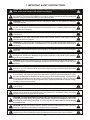
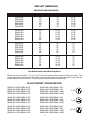
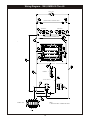
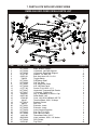
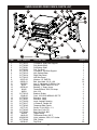
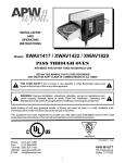
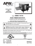
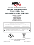
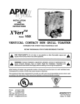
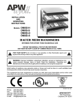
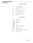
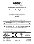
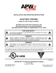
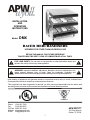
R
INSTALLATION
AND
OPERATING
INSTRUCTIONS
Model:
DMX
RACER MERCHANDISERS
INTENDED FOR OTHER THAN HOUSEHOLD USE
RETAIN THIS MANUAL FOR FUTURE REFERENCE
TOASTER MUST BE KEPT CLEAR OF COMBUSTIBLES AT ALL TIMES
!
FOR YOUR SAFETY: Do not store or use gasoline or other flammable vapors and
liquids in the vicinity of this or any other appliance.
!
!
WARNING: Improper installation, adjustment, alteration, service or maintenance can
cause property damage, injury or death. Read the Installation, Operating and
Maintenance Instructions thoroughly before installing or servicing this equipment.
!
Initial heating of appliance may generate smoke or fumes and must be done in a well ventilated area.
Overexposure to smoke or fumes may cause nausea or dizziness.
This equipment has been engineered to provide you with year-round dependable service when used
according to the instructions in this manual and standard commercial kitchen practices.
ANSI/NSF4
P/N 21776440 12/03
Phone:
Fax:
Toll Free:
Website:
E-mail:
(214) 421-7366
(214) 565-0976
(800) 527-2100
www.apwwyott.com
[email protected]
APW WYOTT
729 Third Avenue
Dallas, TX 75226
1
IMPORTANT FOR FUTURE REFERENCE
Please complete this information and retain this manual for the life of the equipment. For
Warranty Service and/or Parts, this information is required.
Model Number
Serial Number
Notes:
2
Date Purchased
APW Wyott takes pride in the design and quality of our products. When used as intended and with proper
care and maintenance, you will experience years of reliable operation from this equipment. To ensure best
results, it is important that you read and follow the instructions in this manual carefully.
Installation and start-up should be performed by a qualified installer who thoroughly read, understands and
follows these instruction.
If you have questions concerning the installation, operation, maintenance or service of this product, contact
APW Wyott Foodservice Equipment Company’s “ Technical Service Department”.
SAFETY PRECAUTIONS
Before installing and operating this equipment be sure everyone involved in its operation are fully trained
and are aware of all precautions. Accidents and problems can result by a failure to follow fundamental rules
and precautions.
The following words and symbols, found in this manual, alert you to hazards to the operator, service
personnel or the equipment. The words are defined as follows:
!
DANGER: This symbol warns of imminent hazard which will result in serious injury or death.
!
!
WARNING: This symbol refers to a potential hazard or unsafe practice, which could result in
serious injury or death.
!
!
CAUTION: This symbol refers to a potential hazard or unsafe practice, which may result in minor or
moderate injury or product or property damage.
!
!
NOTICE: This symbol refers to information that needs special attention or must be fully understood
even though not dangerous.
!
TABLE OF CONTENTS
SECTION
ITEM
PAGE
1
Important Safety Instructions
4
2
Installation
All Models
Location
5
5
5
3
Operation
Unit Dimensions
Plug/Cordset Configuration
5
6
6
4
Electrical Specifications & Diagrams
Wiring Diagram 120V Units, DMXD-30 thru 42
Wiring Diagram 120/208V Units, DMXD-48 thru 60
Wiring Diagram 120V Units, DMXS-30 thru 60
7
8
9
10
5
Maintenance
General
Cleaning
Display Light Replacement
11
11
11
11
6
Accessories
Stainless Steel Dividers
11
11
7
Parts Lists w/Exploded Views
DMXS-36H
DMXS-36S
DMXD-36H
DMXD-36S
12
12
13
14
15
8
Warranty
16
3
1. IMPORTANT SAFETY INSTRUCTIONS
!
IMPORTANT: Read the following important safety instructions to avoid personal injury or
death, and to avoid damage to the equipment or property.
!
!
WARNING: Plug unit into a properly grounded electrical outlet of the correct voltage, size and plug
configuration. If the plug and receptacle do not match, contact a qualified electrician to determine
the proper voltage and size and install the proper electrical outlet.
!
!
WARNING: Unit is not waterproof. DO NOT submerge in water. Do not operate if it has been
submerged in water.
!
!
WARNING: To avoid any injury, turn the power switch off at the fuse disconnect switch/circuit
breaker or unplug the unit from the power source and allow to cool completely before performing
any maintenance or cleaning.
!
!
WARNING: To avoid electrical shock, always unplug the unit before performing cleaning or
maintenance.
!
!
WARNING: Do not place food product directly onto hardcoat surface. Food product must be
wrapped, boxed or on a food pan.
!
!
WARNING: For safe and proper operation, the unit must be located a reasonable distance from
combustible walls and materials. If safe distances are not maintained, discoloration or combustion
could occur.
!
!
WARNING: To avoid electrical shock or personal injury, do not steam clean or use excessive water
on the unit.
!
!
WARNING: Only light bulbs which meet or exceed N.S.F. Standards, specifically designed for food
holding areas must be used. Breakage of light bulbs not specially coated could result in personal
injury and/or food contamination.
!
!
WARNING: If service is required on this unit, contact your authorized APW Wyott Service Agent, or
contact the APW Wyott Service Department directly at (214) 421-7366 or (800) 527-2100; fax (214)
565-0976.
!
!
WARNING: This product has no “user” serviceable parts. To avoid damage to the unit or injury to
personnel, use only Authorized APW Wyott Service Agents and genuine APW Wyott Parts when
service is required..
!
!
WARNING: Genuine APW Wyott Replacement Parts are specified to operate safely in the
environments in which they are used. Some aftermarket or generic replacement parts do not have
the characteristics that will allow them to operate safely in APW Wyott equipment. It is essential to
use APW Wyott Replacement Parts when repairing APW Wyott equipment. Failure to use APW
Wyott Replacement Parts may subject operators of the equipment to hazardous electrical voltage,
resulting in electrical shock or burn.
!
!
CAUTION: Some exterior surfaces on the unit will get hot. Use caution when touching these areas
to avoid injury.
!
!
CAUTION: Locate the unit at the proper counter height, in an area that is convenient for use. The
location should be level to prevent the unit or it’s contents from accidentally falling, and strong
enough to support the weight of the unit and food.
!
!
CAUTION: The National Sanitation Foundation (NSF) requires that units over 36” (91 cm) in length
or weighing more than 80 lbs. (36 kg) to be either sealed or raised on the installation surface. If this
unit cannot be sealed at the point of use, 4” (10 cm) legs are included to allow for proper cleaning
access below unit.
!
!
CAUTION: Use only non-abrasive cleaners. Abrasive cleaners could scratch the finish of your unit,
marring it’s appearance and making it susceptible to dirt accumulation.
!
!
CAUTION: Only soft cleaning cloths should be used to clean breath protector(s). Breath
protector(s) are made of shatterproof polycarbonate and will scratch if proper care is not taken.
!
4
2. INSTALLATION
ALL MODELS
All APW/Wyott Racer Merchandisers are shipped with most components pre-assembled. Care should be
taken when unpacking shipping carton to avoid damage to unit and components enclosed.
1.
Remove unit from box.
2.
Remove information packet.
3.
Remove tape and protective packaging from all surfaces of unit.
4.
The unit is supplied with product divider bars. To install them, simply place the bars in the
channels provided. The bars can be readily adjusted to separate your holding areas as
needed.
LOCATION
NOTE: The unit must be transported in the upright position.
For proper operation and maximum performance, locate the Racer Merchandiser in an area where the
ambient air temperature is constant and is a minimum of 70°F (21°C). Areas which are susceptible to active
air movements or currents should be avoided, i.e. near exhaust fans or hoods and air conditioning ducts.
!
WARNING: For safe and proper operation, the unit must be located a reasonable distance from
combustible walls and materials. If safe distances are not maintained, discoloration or combustion
could occur.
!
!
CAUTION: Locate the unit at the proper counter height, in an area that is convenient for use. The
location should be level to prevent the unit or it’s contents from accidentally falling, and strong
enough to support the weight of the unit and food.
!
!
CAUTION: The National Sanitation Foundation (NSF) requires that units over 36” (91 cm) in length
or weighing more than 80 lbs. (36 kg) to be either sealed or raised on the installation surface. If this
unit cannot be sealed at the point of use, 4” (10 cm) legs are included to allow for proper cleaning
access below unit.
!
3. OPERATION
The Racer Merchandiser’s power is controlled by the ON/OFF toggle switch. The switch must be on the ON
position for the unit to function.
The thermostatically controlled base and rear overhead element can be set to any desired heating level as
indicated on the control plate.
NOTE: Main power switch must be in the ON position for the heated base to function.
!
CAUTION: Some exterior surfaces on the unit will get hot. Use caution when touching these areas
to avoid injury.
!
!
WARNING: Do not place food product directly onto hardcoat surface. Food product must be
wrapped, boxed or on a food pan.
!
5
DMX UNIT DIMENSIONS
DMX RACER MERCHANDISERS
MODEL NUMBER
WIDTH
HEIGHT
DEPTH
DMXS-30H
DMXS-36H
DMXS-42H
DMXS-48H
DMXS-54H
DMXS-60H
30"
36"
42"
48"
54"
60"
18"
18"
18"
18"
18"
18"
27.25"
27.25"
27.25"
27.25"
27.25"
27.25"
DMXD-30H
DMXD-36H
DMXD-42H
DMXD-48H
DMXD-54H
DMXD-60H
30"
36"
42"
48"
54"
60"
27.50"
27.50"
27.50"
27.50"
27.50"
27.50"
27.25"
27.25"
27.25"
27.25"
27.25"
27.25"
DMXS-30S
DMXS-36S
DMXS-42S
DMXS-48S
DMXS-54S
DMXS-60S
30"
36"
42"
48"
54"
60"
23"
23"
23"
23"
23"
23"
27"
27"
27"
27"
27"
27"
DMXD-30S
DMXD-36S
DMXD-42S
DMXD-48S
DMXD-54S
DMXD-60S
30"
36"
42"
48"
54"
60"
32.75"
32.75"
32.75"
32.75"
32.75"
32.75"
27"
27"
27"
27"
27"
27"
The Model Numbers And What They Mean:
DMX is just the model name. The "S" or the "D" after the model number stands for Single or Double. The
number after the first part of the model number is the complete width of the countertop area. The (H) after the
number stands for Horizontal units. The (S) after the number stands for Slanted units.
PLUG/CORDSET CONFIGURATION
DMXS-30S USES NEMA 5-15P
DMXS-30H USES NEMA 5-15P
DMXD-30S USES NEMA 5-15P
DMXD-30H USES NEMA 5-15P
DMXS-48S USES NEMA 5-15P
DMXS-48H USES NEMA 5-15P
DMXD-48S USES NEMA 14-20P
DMXD-48H USES NEMA 14-20P
5-15P
DMXS-36S USES NEMA 5-15P
DMXS-36H USES NEMA 5-15P
DMXD-36S USES NEMA 5-15P
DMXD-36H USES NEMA 5-15P
DMXS-54S USES NEMA 5-15P
DMXS-54H USES NEMA 5-15P
DMXD-54S USES NEMA 14-20P
DMXD-54H USES NEMA 14-20P
5-20P
DMXS-42S USES NEMA 5-15P
DMXS-42H USES NEMA 5-15P
DMXD-42S USES NEMA 5-20P
DMXD-42H USES NEMA 5-20P
DMXS-60S USES NEMA 5-20P
DMXS-60H USES NEMA 5-20P
DMXD-60S USES NEMA 14-20P
DMXD-60H USES NEMA 14-20P
14-20P
6
4. DMX ELECTRICAL SPECIFICATIONS
DMX UNITS
Over Head
Voltage
DMXS-30S 120
DMXS-30H
DMXD-30S 120 /
DMXD-30H
DMXS-36S 120
DMXS-36H
DMXD-36S 120 /
DMXD-36H
DMXS-42S 120
DMXS-42H
DMXD-42S 120 /
DMXD-42H
DMXS-48S 120
DMXS-48H
DMXD-48S 120 /
DMXD-48H
DMXS-54S 120
DMXS-54H
DMXD-54S 120 /
DMXD-54H
DMXS-60S 120
DMXS-60H
DMXD-60S 120 /
DMXD-60H
!
208
208
208
Blanket
Wattage Qty. Wattage
Bulb
Qty. Wattage
Total W Unit Amps
Qty.
130
2
270
1
40
4
690
5.75
130
4
270
2
40
8
1380
11.5
155
2
350
1
40
4
820
6.8333333
155
4
350
2
40
8
1640
13.666667
215
2
397
1
40
4
987
8.225
215
4
397
2
40
8
1974
16.45
310
2
455
1
40
4
1235
10.291667
310
4
455
2
40
8
2470
11.875
355
2
515
1
40
4
1385
11.541667
355
4
515
2
40
8
2770
13.317308
400
2
578
1
40
4
1538
12.816667
400
4
578
2
40
8
3076
14.788462
WARNING: Plug cabinet into a properly grounded electrical outlet of the correct voltage, size and
plug configuration. If the plug and receptacle do not match, contact a qualified electrician to
determine the proper voltage and size and install the proper electrical outlet.
7
!
Wiring Diagram - 120V Units DMXD-30 Thru 42
PILOT LIGHT
PILOT LIGHT
P
P
7
25
27
5
LOWER OVERHEAD ELEMENT FRONT
UPPER OVERHEAD ELEMENT FRONT
28
40W BULBS
40W BULBS
23
8
24
40W BULBS
LOWER OVERHEAD ELEMENT REAR
30
9
15
10
26
14
32
N
N
L1
L1
11
12
31
N
34
N
L1
L1
17
16
BLANKET ELEMENT
BLANKET ELEMENT
36
4
3
29
UPPER OVERHEAD ELEMENT REAR
40W BULBS
33
35 1
18
2
39
THERMOSTAT
37
THERMOSTAT
13
22
TOGGLE SWITCH
TOGGLE SWITCH
19
21
1
38
TERMINAL BLOCK
GND
L1
N
8
6
NOTE:
1) WATTAGES WILL CHANGE PER UNIT.
2
Wiring Diagram - 120/208V Units DMXD-48 Thru 60
PILOT LIGHT
PILOT LIGHT
P
P
7
25
27
5
LOWER OVERHEAD ELEMENT FRONT
UPPER OVERHEAD ELEMENT FRONT
28
40W BULBS
8
40W BULBS
23
40W BULBS
29
10
26
15
N
31
N
12
N
L2
L2
L1
34
11
N
L1
16
17
BLANKET ELEMENT
BLANKET ELEMENT
36
35
18
39
6
13
THERMOSTAT
37
9
LOWER OVERHEAD ELEMENT REAR
30
32
4
3
24
UPPER OVERHEAD ELEMENT REAR
33
40W BULBS
THERMOSTAT
22
19
TOGGLE SWITCH
2
TOGGLE SWITCH
21
14
1
38
TERMINAL BLOCK
NOTE:
1) WATTAGES WILL CHANGE PER UNIT.
N GND L2 L1
9
Wiring Diagram - 120V, DMXS-30 Thru 60
PILOT LIGHT
P
5
7
LOWER OVERHEAD ELEMENT FRONT
8
40W BULBS
40W BULBS
3
4
LOWER OVERHEAD ELEMENT REAR
9
15
10
11
12
N
N
L1
L1
16
17
14
BLANKET ELEMENT
18
13
6
THERMOSTAT
2
TOGGLE SWITCH
19
1
NOTE:
1) WATTAGES WILL CHANGE PER UNIT.
TERMINAL BLOCK
GND
N
L1
10
5. MAINTENANCE
GENERAL
The APW/Wyott Racer Merchandisers are designed for maximum durability and performance, with
minimum maintenance.
!
WARNING: To avoid any injury, turn the power switch off at the fuse disconnect switch/circuit
breaker or unplug the unit from the power source and allow to cool completely before performing
any maintenance or cleaning.
!
!
WARNING: To avoid electrical shock or personal injury, do not steam clean or use excessive water
on the unit.
!
!
WARNING: Unit is not waterproof. DO NOT submerge in water. Do not operate if it has been
submerged in water.
!
!
WARNING: To avoid electrical shock, always unplug the unit before performing cleaning or
maintenance.
!
CLEANING
To preserve the bright finish of the Racer Merchandiser, it is recommended that the exterior and interior
surfaces be wiped daily with a damp cloth. Stubborn stains may be removed with a good non-abrasive
cleanser. Hard to reach areas should be cleaned with a small brush and mild soap.
!
CAUTION: Use only non-abrasive cleaners. Abrasive cleaners could scratch the finish of your unit,
marring it’s appearance and making it susceptible to dirt accumulation.
!
Clean the glass sides using a common glass cleaner.
DISPLAY LIGHT BULB REPLACEMENT
The display light is an incandescent light bulb which illuminates the warming area. The bulb has a special
coating to guard against injury and food contamination in the event of breakage.
1.
To replace the light bulb, disconnect the power supply and wait until the unit has cooled.
2.
Bulbs have a threaded base. Unscrew the light bulb from the unit and replace it with a new
specially coated incandescent bulb.
NOTE: APW Wyott shatter-resistant light bulbs meet N.S.F. Standards for food holding and display areas.
!
WARNING: Only bulbs which meet or exceed N.S.F. Standards, specifically designed for food
holding areas must be used. Breakage of bulbs not specially coated could result in personal injury
and/or food contamination.
!
!
WARNING: If service is required on this unit, contact your authorized APW Wyott Service Agent, or
contact the APW Wyott Service Department directly at (214) 421-7366 or (800) 527-2100; fax (214)
565-0976.
!
!
WARNING: This product has no “user” serviceable parts. To avoid damage to the unit or injury to
personnel, use only Authorized APW Wyott Service Agents and genuine APW Wyott Parts when
service is required..
!
!
WARNING: Genuine APW Wyott Replacement Parts are specified to operate safely in the
environments in which they are used. Some aftermarket or generic replacement parts do not have
the characteristics that will allow them to operate safely in APW Wyott equipment. It is essential to
use APW Wyott Replacement Parts when repairing APW Wyott equipment. Failure to use APW
Wyott Replacement Parts may subject operators of the equipment to hazardous electrical voltage,
resulting in electrical shock or burn.
!
6. ACCESSORIES
STAINLESS STEEL DIVIDER RODS
Additional stainless steel divider rods help to keep product separate in the channels.
11
7. PARTS LISTS WITH EXPLODED VIEWS
DMXS-36H EXPLODED VIEW & PARTS LIST
26
11
15
4
25
16
24
6
8
13
21
18
28
20
10
7
27
19
2
23
17
5
12
22
3
14
ITEM
PART NUMBER
1
2
3
4
5
6
7
8
9
10
11
12
13
14
15
16
17
18
19
20
21
22
23
24
25
26
27
28
217762-48
217763-86
217763-85
85157-00
82652-01
784652
217762-81
217762-82
217763-87
217763-90
81777-00
217762-47
217762-17
8632000
89675-00
15346-00
89145
217762-16
89054
217762-21
217764-02
217764-29
217762-45
217762-46
14815-00
456530-00
217762-44
83530-00
9
14
1
DESCRIPTION
QUANTITY
Base, Bottom Straight
U-Channel, Left Side Support
U-Channel, Right Side Support
Washer, 1/2" SAE ZN
Bolt, Hex Head 1/2-13 x 3/4
Toggle Switch
S/A Bottom Shelf
S/A Top Shelf
A/D, Right Side Panel
A/D, Left Side Panel
Screw, Fl Hd 10-32 x 1 ½
Horizontal, Tempered Side Panels
U-Channel, Flexible 24"
Leg, 4" Adjustable, 2,000 Lb. Cap.
Strain Relief, 14/3
Cord, 14/3 HSJO NEMA 6-20P 72"
Terminal Block, 300V, 30 Amps
Bracket, Divider
Nut, 6-32
Extrusion, Insert
Extrusion, Insert
Insert, Angled Extrusion
End Cap, F/L & F/R
End Cap, B/L & B/R
Thermostat, Bulb, 250° F
Light, Indicator, 250V, 1/2" Amber
Rod, Divider
Pop Rivet
12
1
1
1
12
12
1
1
1
1
1
8
2
4
4
1
1
1
2
2
3
1
3
4
4
1
1
4
18
DMXS-36S EXPLODED VIEW & PARTS LIST
13
14
27
19
16
26
15
25
20
2
24
6
7
21
22
29
17
3
4
5
28
11
23
18
10
9
12
8
8
ITEM
1
2
3
4
5
6
7
8
9
10
11
12
13
14
15
16
17
18
19
20
21
22
23
24
25
26
27
28
29
1
PART NUMBER
217764-12
217762-82
217762-81
217764-13
217762-48
85157-00
82652-01
8632000
89785-00
89145
89054
217765-22
217765-23
89675-00
15346-00
81777-00
217762-21
217764-29
217764-02
217762-17
217762-42
217762-16
217762-45
217762-46
784652
14815-00
456530-00
217762-44
83530-00
DESCRIPTION
QUANTITY
U-Channel, Right Side Support
S/A Top Shelf
S/A Bottom Shelf
Support, Left Side
WA, Bottom Base
Washer, 1/2" SAE ZN
Bolt, Hex Head 1/2-13 x 3/4
Leg, 4" Adjustable, 2,000 Lb. Cap.
Bushing, 1" Snap, Heyco
Terminal Block, 300V, 30 Amps
Nut, 6-32
A/D, Right Side Panel
A/D, Left Side Panel
Strain Relief, 14/3
Cord, 14/3 HSJO NEMA 6-20P 72"
Screw, Fl Hd 10-32 x 1 ½
Extrusion, Insert
Insert, Angled Extrusion
Extrusion, Insert
U-Channel, Flexible 24"
Tempered Side Panels
Bracket, Divider
End Cap, F/L & F/R
End Cap, B/L & B/R
Toggle Switch
Thermostat, Bulb, 250° F
Light, Indicator, 250V, 1/2" Amber
Rod, Divider
Pop Rivet
13
1
1
1
1
1
12
12
4
2
1
2
1
1
1
1
8
3
3
1
4
2
2
4
4
1
1
1
4
18
DMXD-36H EXPLODED VIEW & PARTS LIST
15
28
23
22
14
29
9
5
7
20
10
3
12
4
26
25
8
19
24
16
1
13
ITEM
PART NUMBER
1
2
3
4
5
6
7
8
9
10
11
12
13
14
15
16
17
18
19
20
21
22
23
24
25
26
27
28
29
217762-59
217762-58
217762-81
217762-48
85157-00
82652-01
217762-82
217762-80
217762-55
217762-56
217762-16
217762-21
8632000
81777-00
217762-57
217764-29
217762-17
217762-47
217762-45
217762-46
784652
14815-00
456530-00
89145
89054
217762-44
83530-00
89675-00
15346-00
18
17
27
2
21
11
6
13
DESCRIPTION
QUANTITY
U-Channel, Right Side Support
Support, Left Side
S/A Bottom Shelf
Base, Bottom Straight
Washer, 1/2" SAE ZN
Bolt, Hex Head 1/2-13 x 3/4
S/A, Top Shelf
S/A, Middle Shelf
Right Side Panel
Left Side Panel
Bracket, Divider
Extrusion, Insert
Leg, 4" Adjustable, 2,000 Lb. Cap.
Screw, Fl Hd 10-32 x 1 ½
Extrusion, Insert
Insert, Angled Extrusion
U-Channel, Flexible 24"
Horizontal, Tempered Side Panels
End Cap, F/L & F/R
End Cap, B/L & B/R
Toggle Switch
Thermostat, Bulb, 250° F
Light, Indicator, 250V, 1/2" Amber
Terminal Block, 300V, 30 Amps
Nut, 6-32
Rod, Divider
Pop Rivet
Strain Relief, 14/3
Cord, 14/3 HSJO NEMA 6-20P 72"
14
1
1
1
1
16
16
1
1
1
1
4
5
4
8
1
5
8
4
6
6
2
2
2
1
2
8
30
1
1
DMXD-36S EXPLODED VIEW & PARTS LIST
23
19
27
4
28 12
16
17
9
21
26
10
2
25
30
22
18
8
24
13
15
29
3
6
14
5
20
1
11
ITEM
PART NUMBER
1
2
3
4
5
6
7
8
9
10
11
12
13
14
15
16
17
18
19
20
21
22
23
24
25
26
27
28
29
30
217762-13
217762-80
217762-81
217762-82
217762-14
217762-12
217764-14
217764-15
85157-00
82652-01
8632000
89111
89785-00
89145
89054
217762-16
15346-00
217762-21
217762-57
217764-29
217762-17
217762-42
81777-00
217762-45
217762-46
784652
14815-00
456530-00
217762-44
83530-00
7
11
DESCRIPTION
QUANTITY
U-Channel, Right Side Support
S/A, Middle Shelf
S/A Bottom Shelf
S/A, Top Shelf
U-Channel, Left Side Support
W/A, Bottom Base
Right Side Panel
Left Side Panel
Washer, 1/2" SAE ZN
Bolt, Hex Head 1/2-13 x 3/4
Leg, 4" Adjustable, 2,000 Lb. Cap.
Bushing, Strain Relief SR-7W-2
Bushing, 1" Snap, Heyco
Terminal Block, 300V, 30 Amps
Nut, 6-32
Bracket, Divider
Cord, 14/3 HSJO NEMA 6-20P 72"
Extrusion, Insert
Extrusion, Insert
Insert, Angled Extrusion
U-Channel, Flexible 24"
Tempered Side Panels
Screw, Fl Hd 10-32 x 1 ½
End Cap, F/L & F/R
End Cap, B/L & B/R
Toggle Switch
Thermostat, Bulb, 250° F
Light, Indicator, 250V, 1/2" Amber
Rod, Divider
Pop Rivet
15
1
1
1
1
1
1
1
1
16
16
4
1
2
1
2
4
1
5
1
5
8
4
8
6
6
2
2
2
8
30
8. APW WYOTT EQUIPMENT LIMITED WARRANTY
APW Wyott Foodservice Equipment Company warrants it's equipment against defects in materials and workmanship, subject to the
following:
This warranty applies to the original owner only and is not assignable.
Should product fail to function in its intended manner under normal use within the limits defined in this warranty, at the option of APW
Wyott such product will be repaired or replaced by APWWyott or itsAuthorized Service Agency.APW Wyott will only be responsible
for charges incurred or service performed by its Authorized Service Agencies. The use of other than APW Wyott Authorized Service
Agencies will void this warranty and APW Wyott will not be responsible for such work or any charges associated with same. The
closest APW Wyott Authorized Service Agent must be used.
This warranty covers products shipped into the 48 contiguous United States, Hawaii, metropolitan areas of Alaska and Canada. There
will be no labor coverage for equipment located on any island not connected by roadway to the mainland.
Time Period
One year parts, one year labor, effective from the date of purchase by the original owner. The Authorized Service Agency may, at their
option, require proof of purchase. Parts replaced under this warranty are warranted for the un-expired portion of the original product
warranty only.
Exceptions
*Gas/Electric Cookline Models GCB, GCRB, GF, GGM, GGT, GHP-H, EF, EG, EHP Three (3) Year Warranty on all
component parts, except switches and thermostats. (2 additional years on parts only. No labor on second or third year.)
*Heat Strips Models OH & FD Two (2) YearWarranty on element only No labor second year.
*Glass Windows, Door Seals, Rubber Seals, Light Bulbs, Broiler Briquettes 90 Day Material Only No Labor.
In all cases, parts covered by extended warranty will be shipped FOB the factory after the first year.
Portable Carry In Products
Equipment weighing over 70 pounds or permanently installed will be serviced on-site as per the terms of this warranty. Equipment
weighing 70 pounds or under, and which is not permanently installed, i.e. with cord and plug, is considered portable and is subject to
the following warranty handling limitations. If portable equipment fails to operate in its intended manner on the first day of
connection, or use, at APW Wyott's option or its Authorized Service Agency, it will be serviced on site or replaced.
From day two through the conclusion of this warranty, portable units must be taken to or sent prepaid to the APW Wyott Authorized
Service Agency for in-warranty repairs. No mileage or travel charges are allowed on portable units after the first day of use. If the
customer wants on-site service, they may receive same by paying the travel and mileage charges. Exceptions to this rule: (1)
countertop warmers and cookers, which are covered under the Enhanced Warranty Program, and (2) toasters or rollergrills which have
in store service.
Exclusions
The following conditions are not covered by warranty:
*Equipment failure relating to improper installation, improper utility connection or supply and problems due to
ventilation.
*Equipment that has not been properly maintained, calibration of controls, adjustments, damage from improper cleaning
and water damage to controls.
*Equipment that has not been used in an appropriate manner, or has been subject to misuse misapplication, neglect, abuse,
accident, alteration, negligence, damage during transit, delivery or installation, fire, flood, riot or act of god.
*Equipment that has the model number or serial number removed or altered.
If the equipment has been changed, altered, modified or repaired by other than a qualified service technician during or after the
warranty period, then the manufacturer shall not be liable for any damages to any person or to any property, which may result from the
use of the equipment thereafter.
This warranty does not cover services performed at overtime or premium labor rates. Should service be required at times which
normally involve overtime or premium labor rates, the owner shall be charged for the difference between normal service rates and such
premium rates. APW Wyott does not assume any liability for extended delays in replacing or repairing any items beyond its control.
In all cases the use of other than APW Wyott Authorized OEM Replacement Parts will void this warranty.
This equipment is intended for commercial use only. Warranty is void if equipment is installed in other than commercial application.
Water Quality Requirements
Water supply intended for a unit that has in excess of 3.0 grains of hardness per gallon (GPG) must be treated or softened before
being used. Water containing over 3.0 GPG will decrease the efficiency and reduce the operation life of the unit.
Note: Product failure caused by liming or sediment buildup is not covered under warranty.
“THE FOREGOING WARRANTY IS IN LIEU OF ANY AND ALL OTHER WARRANTIES EXPRESSED OR IMPLIED
INCLUDING ANY IMPLIED WARRANTY OR MERCHTABILITY OR FITNESS FOR PARTICLUAR PURPOSES AND
CONSTITUTES THE ENTIRE LIABILITY OF APW WYOTT. IN NO EVENT DOES THE LIMITED WARRANTY
EXTEND BEYOND THE TERMS HEREIN.”
16
15
Phone:
Fax:
Toll Free:
Website:
E-mail:
(214) 421-7366
(214) 565-0976
(800) 527-2100
www.apwwyott.com
[email protected]
APW WYOTT
729 Third Avenue
Dallas, TX 75226
16