1
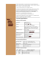
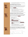
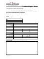
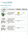
User Guide
2110195 Rev 1.0
December 1999
o Welcome
o Overview
o Components
o Supported Prods.
o Safety Notices
o Specifications
o Installation
o Using AirBooster
o Troubleshooting
o Service
o Contact Us
Welcome to the AirBooster™ 350 RF amplifier
The AirBooster 350 is an intelligent RF amplifier for boosting some Sierra
Wireless Class III (600mW) CDPD devices to Class I (3W). The amplifier is
an "intelligent" booster in that it does not simply apply a fixed gain to a
varying input RF level as a linear amplifier would. Instead, the AirBooster
amplifier takes a constant RF level from the CDPD device and applies as
much gain as the CDPD system requires at that moment.
A GPS Option is also available, adding a GPS receiver inside the package.
This is available as a field upgrade kit or pre-installed at the factory.
Documentation related to GPS is covered in a separate section.
Your AirBooster 350 Components
All AirBooster 350 packages will include the following components:
●
●
●
AirBooster™ 350 RF amplifier.
Power Cable.
Sierra Wireless Product CD-ROM with this Documentation including a
3 Year Warranty.
4 Screws with Washers.
Mounting Template.
● Quick Start Guide.
Units with the factory installed GPS option will also include:
● DB-9 Serial Cable.
Additional accessories are available from Sierra Wireless. These include:
●
●
RF Connector Cables (an assortment of lengths and connector options
are available).
● GPS Options (Factory Installed or Field Upgrade Kit).
● GPS antennas (Magnetic or Hard Mount options).
For details on these and other Sierra Wireless accessories contact sales or
visit our web site.
●
Supported Products
At the time of this writing, the AirBooster 350 RF amplifier is supported by
the following Sierra Wireless products:
AirCard® 350 CDPD Adapter
● SB300 OEM Module
Additional Sierra Wireless products may be added to this list. Consult our
web site for a complete and current list.
●
CAUTION - The AirBooster 350 amplifier is designed to be
used exclusively with supported Sierra Wireless products.
Attaching non-supported devices will not harm the device or the
amplifier but will severely impair transmissions from the device.
o Welcome (top)
o Overview
o Safety Notices
o Hazards
o Regulatory
o Patents
o Specifications
Important Notice
Because of the nature of wireless communications, transmission and
reception of data can never be guaranteed. Data may be delayed, corrupted
(i.e., have errors) or be totally lost. Although significant delays or losses of
data are rare when wireless devices such as the AirBooster 350 RF amplifier
are used in a normal manner with a well-constructed network, they should not
be used in situations where failure to transmit or receive data could result in
damage of any kind to the user or any other party, including but not limited to
personal injury, death, or loss of property. Sierra Wireless, Inc. accepts no
responsibility for damages of any kind resulting from delays or errors in data
transmitted or received using the AirBooster 350 RF amplifier, or for failure
of the AirBooster 350 amplifier to transmit or receive such data.
Safety and Hazards
Do not operate the AirBooster amplifier in areas where blasting is in
progress, where explosive atmospheres may be present, near medical
equipment, near life support equipment, or any equipment which may be
susceptible to any form of radio interference. In such areas, the host
communications device MUST BE TURNED OFF. The RF amplifier can
transmit signals that could interfere with this equipment.
Do not operate your data transmitter in close proximity to any aircraft,
whether the aircraft is on the ground or in flight. Near aircraft, the host
communications device MUST BE TURNED OFF. When operating, the
AirBooster RF amplifier can transmit signals that could interfere with various
onboard systems.
The driver or operator of any vehicle should not operate a wireless data
device while in control of a vehicle. Doing so will detract from the driver or
operator's control and operation of that vehicle. In some states and provinces,
operating such communications devices while in control of a vehicle is an
offence.
WARNING - The FCC has developed guidelines to reduce any
possible hazard due to exposure of the human body to
electromagnetic radiation (i.e. to radio waves). This device is
approved for operation with specific Sierra Wireless modem
transmitters using a 3.0dBd or a 3.4dBd vehicle-mount antenna
with at least 2dB cable loss, as described in the filing. The
combination of cable loss and antenna gain must not exceed an
overall gain of 1dB. The antenna installation must provide a
separation distance of 20cm (8") or more between the antenna
and all persons to satisfy MPE compliance.
WARNING - For FCC compliance only a tested and approved
antenna should be used in conjunction with RG58 cable of at
least 4.5m (14'9") in length. As of this writing the following
antennas have been tested and approved:
● Larsen model MM3800FME
●
Antenna World model CLR-877
Sierra Wireless continues to test other makes and models of
antennas. For the most current list, consult our website.
Regulatory Information
The equipment certifications appropriate to your device are marked on the
device and the accompanying product specific information. Where
appropriate, the use of the equipment is subject to the following conditions:
CAUTION - Unauthorized modifications or changes not
expressly approved by Sierra Wireless, Inc. could void
compliance with regulatory rules, and thereby your authority to
use this equipment.
WARNING (EMI) - United States FCC Information - This
equipment has been tested and found to comply with the limits
pursuant to Part 15 of the FCC Rules. These limits are designed
to provide reasonable protection against harmful interference in
an appropriate installation. This equipment generates, uses, and
can radiate radio frequency energy and, if not installed and used
in accordance with the instructions, may cause harmful
interference to radio communication. However, there is no
guarantee that interference will not occur in a particular
installation. If this equipment does cause harmful interference to
radio or television reception, which can be determined by turning
the equipment off and on, the user is encouraged to try to correct
the interference by one or more of the following measures:
● Reorient or relocate the receiving antenna
● Increase the separation between the equipment and
receiver
● Connect the equipment into an outlet on a circuit different
from that to which the receiver is connected
● Consult the dealer or an experienced radio/TV technician
for help
WARNING (EMI) - Canada - This digital apparatus does not
exceed the Class A limits for radio noise emissions from digital
apparatus as set out in the interference causing equipment
standard entitled "Digital Apparatus", ICES-003 of the
Department of Communications.
Cet appareil numérique respecte les limites de bruits
radioélectriques applicables aux appareils numériques de
Classe A prescrites dans la norme sur le matériel brouilleur:
"Appareils Numériques", NMB-003 édictée par le ministre des
Communications.
Patents and Trademarks
Portions of this product are covered by some or all of the following US
patents: 5515013, 5617106, 5629960, 5682602, 5748449, 5845216, 5845553,
5878234, 5890057, and other patents pending.
©1998, 1999 Sierra Wireless, Inc. All rights reserved.
The information in this manual is subject to change without notice and does
not represent a commitment on the part of Sierra Wireless, Inc. Sierra
Wireless, Inc. shall not be liable for incidental or consequential damages
resulting from the furnishing, performance, or use of this manual.
AirBooster™ is a trademark of Sierra Wireless, Inc.
AirCard® is a registered trademark of Sierra Wireless, Inc.
All other brand or product names, logos, trademarks, etc. mentioned in this
manual are owned by their respective companies.
o Welcome (top)
o Overview
o Safety Notices
o Specifications
o RF Amplifier
o Environmental
o DB-9 Pinouts
Technical Specifications
AirBooster 350 RF Amplifier
Compliance:
CDPD Release 1.1
FCC Parts 15 and 22
Voltage:
Standard vehicle battery
11 - 16 Vdc (13.8 Vdc nominal)
Power Reduction Mode: 105mA (typical)
Enabled (Receive): 128mA (287mA w/GPS)
Maximum Transmit: 1.63A (1.8A w/GPS)
Class I mobile
Up to 4.5 Watts ERP from device
(depending on antenna/cabling)
Current:
Transmitter Power:
CDPD Device Interface:
SMA RF connector
Antenna Interface:
GPS Interface:
50 ohm TNC RF connector
DB-9 at RS-232 level
non-standard pinouts.
GPS Antenna Interface:
SMB RF connector
Environmental Specifications
Operating Temp:
Storage Temp:
Humidity:
-30 to +70° C (restricted duty cycle)
-30 to +60° C (un-restriced duty cycle)
-40 to +80° C
5 - 95%, non-condensing
Vibration:
MIL-STD-810E,I-3.4.9.
GPS DB-9 Connector Pinouts
Pin #
1
2
3
RS-232
DCD
RxD
TxD
AirBooster Application
1 Pulse/sec output from GPS module
RxD (from GPS to host)
TxD (from host to GPS)
4
5
DTR
GND
Input (reserved, DTR is accepted)
GND Signal Ground
6
DSR
Output (reserved)
7
RTS
TxD_2 (from host to GPS secondary port)
8
CTS
RxD_2 (from GPS secondary port to host)
9
RI
Output (reserved, disregard signal)
Document Map
Use the document map to jump to a subject of interest or turn the pages to
read the full manual.
Back to Product List
Page Top
©1999 Sierra Wireless, Inc. All rights reserved.
Next Page
o Welcome
o Installation
o Overview
o Mounting
o Host Cable
o Antenna
o Power Cable
o Using AirBooster
o Troubleshooting
o Service
o Contact Us
User Guide
Installation Overview
This section contains instructions for installing the AirBooster RF amplifier.
Before you can use your AirBooster amplifier for the first time you must:
1. Mount the AirBooster amplifier in your vehicle. (more...)
2. Install the CDPD device cabling and connector. (more...)
3. Install the antenna, cabling, and connector. (more...)
4. Install and connect the power cable. (more...)
Installation of the optional GPS is covered in separate sections on the GPS
generally, the Field Upgrade Kit, and its related software.
o Installation (top)
o Mounting
o Host Cable
o Antenna
o Power Cable
Mounting the AirBooster RF Amplifier
Your AirBooster RF amplifier is designed for mounting in a vehicle, either in
the trunk or some other suitable location.
1. Choose a location within the vehicle which:
❍ Allows access to the connectors on the front panel.
❍ Provides access for installing needed connector cables.
❍ Avoids excessive heat from sources such as the engine
compartment, heaters, or vehicle exhaust.
❍ Protects it from weather and excessive moisture. If mounted in
the passenger compartment, ensure that spills cannot leak into
the unit.
2. Use the mounting template supplied to mark the location of the
mounting holes.
3. Drill the required pilot holes (5/32").
4. Use the four mounting screws supplied to secure the booster through
the holes along the base of the booster case.
o Installation (top)
o Mounting
o Host Cable
o Antenna
o Power Cable
Install CDPD Cabling and Connector
Due to the variation in required cable lengths and connector types that may be
needed between the booster and the host CDPD device, there is no host cable
in the AirBooster 350 RF amplifier package. These cables are ordered
separately from Sierra Wireless.
The steps involved in the connection are:
1. Determine a suitable location for the host end connection.
2. Thread the cable through the vehicle so that the SMA connector is
available for connection to the booster.
3. Connect the SMA connector to the AirBooster 350 MODEM
connector. Tighten firmly by hand; do not use tools.
o Installation (top)
o Mounting
o Host Cable
o Antenna
o Power Cable
Installing the Antenna, Cable, and Connector
Variation in the installation requirements for antenna type and cable lengths
prevent inclusion of these components in the product package. Antennas and
cables can be ordered separately from Sierra Wireless or other suppliers.
The requirements for the antenna are:
● Standard cellular frequencies.
● 50 Ohm impedance.
● TNC connector (for the booster end).
● 3dBd gain (recommended but not required)
●
Approved Manufacturer and Model
The steps involved in the installation and connection are:
1. Determine a suitable location for the antenna at least 50cm from
bystanders (open air exposure). Mount it according to the instructions
provided with it.
2. Thread the cable through the vehicle so that the TNC connector is
available for connection to the booster.
3. Connect the TNC connector to the AirBooster 350 ANTENNA
connector. Tighten firmly by hand; do not use tools.
o Installation (top)
o Mounting
o Host Cable
o Antenna
o Power Cable
Connecting Power to the AirBooster 350 Amplifier
A power cable is provided in the AirBooster 350 package. The recommended
connection is illustrated below.
Ignition Sense Considerations
The white ignition sense line controls a power switch within the booster used
to reduce power consumption when the vehicle is switched off and there is
no CDPD device connected. The ignition sense is used in conjunction with a
CDPD device detection switch. If either of these is on, the AirBooster
amplifier (and the optional GPS module) is enabled. Only if the ignition and
the CDPD device connection are both off is the power reduction enabled.
In power reduction mode, an installed GPS module will stop tracking
satellites and is not available for communication. It will still receive sufficient
power to maintain its real-time clock and RAM data. This ensures a warm
start condition when the GPS becomes fully enabled.
It is permissible to connect the white ignition sense to the red 12V power line.
This will mean the AirBooster amplifier will be on at all times and the current
draw on the battery will be slightly higher than with power reduction enabled.
This additional draw amounts to approximately 25mA for a unit without the
GPS option and 180mA for units with the option.
NOTE - Users With the GPS Option - When the AirBooster
amplifier switches to the power reduction mode, access to the
GPS is lost. If you need access to the GPS module even when the
vehicle is off and there is no CDPD device connected, you must
connect the ignition sense to the 12V line or provide a switch on
the ignition sense line to ensure the GPS module can be switched
on when needed.
NOTE - Vehicle Battery Life - Although battery life varies
widely based on type, age, environment, and other issues, you
should be aware of the drain when the vehicle is parked for
extended periods. Using a sample case of a battery with 30Amp
hours of storage the following life expectancies would apply
given the AirBooster as the only device drawing power. There are
likely other vehicle systems (clocks, alarms, etc.) that also draw
power when the vehicle is parked.
without GPS with GPS
Switch Off 12 days
11.5 days
Switch On
4.3 days
9.7 days
Power Connection Procedure
1. Switch off the vehicle.
2. Thread the cable through the vehicle.
3. Connect the Black (Ground) wire to the negative terminal of the
battery.
4. Connect the White (Ignition Sense) wire to a suitable location, either a
switch (ignition or accessories) or directly to the Red (12V power) line.
5. Connect the Red (12V) wire to the positive terminal of the battery.
6. Insert the power connector into the AirBooster 350 amplifier.
Installation Completion
Upon successful completion of the installation, the amplifier should show a lit
green LED for POWER. This will be on whether power reduction is used or
not. It indicates that the AirBooster 350 amplifier is receiving 12V power and
is available for use.
Document Map
Back to Product List
Previous Page
Page Top
©1999 Sierra Wireless, Inc. All rights reserved.
Next Page
o Welcome
o Installation
User Guide
o Using AirBooster
o Operation
o Care & Handling
o Troubleshooting
o Service
o Contact Us
Using AirBooster
This section deals with the day to day use of the AirBooster amplifier after
installation, as well as the care and handling to provide long life. Details on
the use of the optional GPS module are covered in another section.
Operating the AirBooster RF Amplifier
Enabling of the AirBooster 350 RF amplifier requires only that the power be
connected. The amplifier should show a lit green LED for POWER
indicating that it is available for use. This LED is on whether power reduction
is enabled or not.
As soon as a supported device is connected to the booster, it will
automatically be detected and the amplifier will begin operation. The ignition
of the vehicle does not need to be on. When a host device is detected, the
STATUS indicator LED will light green.
During normal operation the STATUS indicator will blink intermittently.
The light remains on while the host device is connected and will go off only
during active data transmission.
To ensure that your AirBooster does not transmit in environments where use
of cellular equipment is hazardous, you must disconnect the CDPD device.
o Using AirBooster (top)
o Operation
o Care & Handling
Document Map
Back to Product List
Caring for Your AirBooster Amplifier
The AirBooster 350 is designed to withstand the normal conditions found in
vehicles, with regard to vibration, shock, and temperature. Provided adequate
care is taken in selecting a mounting location, there should not be any need
for further attention.
Previous Page
Page Top
©1999 Sierra Wireless, Inc. All rights reserved.
Next Page
o Welcome
o Installation
o Using AirBooster
o Troubleshooting
o Service
o Contact Us
User Guide
Troubleshooting
For the most up-to-date and detailed troubleshooting tips, visit the Sierra
Wireless AirBooster 350 website. There is a separate section for
troubleshooting GPS issues.
The most common cause of problems with the AirBooster 350 RF amplifier is
with connectors and cables. Always check the connectors before calling
Technical Support.
Problem
CDPD device can receive but not
transmit.
STATUS indicator fails to light
when CDPD device is connected.
STATUS indicator is working
normally but CDPD device fails to
register, receive, or transmit.
STATUS indicator is dim or
flickering. CDPD device is losing
packets or appears to have slower
throughput or does not function at
all.
Document Map
Back to Product List
Previous Page
Suggestion
The device is either not supported by
the booster, or has had its booster
support capability switched off
(+WS214).
Verify that the CDPD device is a
supported model and revision, and is
on (enabled).
Coverage may be unavailable in the
current location.
Verify the antenna connection is
secure and cable is unbroken. Try
another antenna.
Power to the booster has dropped
below 9Vdc. Check the battery being
used to power the booster.
Disconnect the CDPD device from the
booster and use the CDPD device's
own antenna until adequate power can
be restored to the booster.
Page Top
©1999 Sierra Wireless, Inc. All rights reserved.
Next Page
o Welcome
o Installation
o Using AirBooster
o Troubleshooting
User Guide
Warranty and Customer Service
o Service
o Contact Us
o Get Service
o Warranty
For technical support of third-party accessories used with the AirBooster 350
RF amplifier, contact the accessory vendor directly. Sierra Wireless, Inc. does
not provide support for these components.
Customer Service Contacts
o Service (top)
o Contact Us
o Get Service
o Report Form
o Warranty
Help Desk
(604) 231-1128 (06:00 - 17:00 Pacific Time)
[email protected]
Sales Desk
(604) 231-1100 (08:00 - 17:00 Pacific Time)
[email protected]
Web
www.sierrawireless.com
Getting Service
In the event of equipment malfunction, Sierra Wireless, Inc., or one of its
authorized agents should perform all repairs. It is the responsibility of users
requiring service to report the need for service to Sierra Wireless, Inc. or to
one of its authorized agents.
For warranty service or out-of-warranty repair:
1. Contact the Help Desk to determine the nature of the problem. If return
of the product is required they will help you with the rest of this
process.
2. Obtain a Return Material Authorization (RMA) number from the Sierra
Wireless Help Desk.
3. Print and fill out the Problem Sheet (PDF). A MS Word version is
available if you prefer.
Remember: the more detailed your description of the problem, the
faster your booster can be diagnosed and repaired.
4. Return the equipment, with the Problem Sheet enclosed, shipping
pre-paid, to the address specified by the Customer Service
Representative.
o Service (top)
o Contact Us
o Get Service
o Warranty
o Registration
Warranty
Sierra Wireless, Inc. warrants the AirBooster 350 RF amplifier against all
defects in materials and workmanship for a period of three (3) years from the
date of purchase.
The sole responsibility of Sierra Wireless, Inc. under this warranty is limited
to either repair or, at the option of Sierra Wireless, Inc., replacement of the
AirBooster 350 RF amplifier. There are no expressed or implied warranties,
including those of fitness for a particular purpose or merchantability, which
extend beyond the face hereof.
Sierra Wireless, Inc. is not liable for any incidental or consequential damages
arising from the use, misuse, or installation of the AirBooster 350 RF
amplifier.
This warranty does not apply if the serial number label has been removed, or
if the AirBooster 350 RF amplifier has been subjected to physical abuse,
improper installation, or modification.
Warranty Registration
To register the warranty visit our web site and register on-line from the
REGISTER option on the main tab. Alternatively, you can complete and mail
or fax the registration card provided in the package.
Document Map
Back to Product List
Previous Page
Page Top
©1999 Sierra Wireless, Inc. All rights reserved.
Main Page
User Guide Document Map
©1999 Sierra Wireless, Inc. All rights reserved.
Problem Report Sheet
If you are having trouble with your modem, please contact:
Sierra Wireless Technical Support 604-231-1128 (6am to 5pm Pacific Time).
If it is deemed necessary to return the modem for repair, you will be given an RMA number, and asked to fill
out this form and return it with the modem.
Do not return the modem without obtaining an RMA number.
Sierra Wireless Inc.
13575 Commerce Parkway, Suite 150
Richmond, BC V6V 2L1
Canada
Tel. 604.231.1100
Fax. 604.231.1109
Date:
RMA No.
Company Name
Contact
Address
City
State/Province
Zip/Postal Code
Telephone
Fax
Email
Product
Serial Number
ESN:
Host Computer Make
Model
Operating System
To ensure prompt repair, please provide as much detail as possible.
Problem Description
2110125 Rev 1.0
206 -