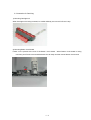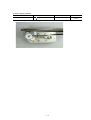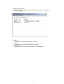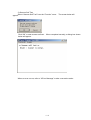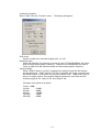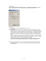
1
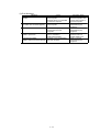
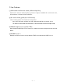
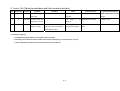
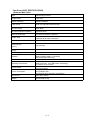
CS 9950F
SERVICE
MANUAL
Canon
Copyright 2004, Canon U.S.A. This technical publication is the proprietary and confidential information of Canon U.S.A. which
shall be retained for reference purposes by Authorized Service Facilities of Canon U.S.A. Its unauthorized use is prohibited.
CanoScan 9950F
SERVICE MANUAL
REVISION 0
JY8-1323-000
COPYRIGHT 2004 CANON INC. CANON CanoScan 9950F 082004
Application
This manual has been issued by Canon Inc. to provide information necessary to self-study
techniques, setting-up, maintenance and repair to technicians who service the target products. This
manual covers all locations where the target products are sold. For this reason, there may be
information in this manual that does not apply to your locality.
Revision
This manual might include technically incorrect descriptions or misprints because the target products
may be improved or changed. For this reason, service information is being published in case of any
changes in this manual. If this manual is having a significant change, in long or in short term, a
revised edition will be carried out.
The following paragraph does not apply to any countries where such provisions are inconsistent with
local law.
Trademarks
The product names and company names described in this manual are the registrered trademarks or
tradmards of the individual companies.
Copyright
The copyright of this manual belongs to Canon Inc. Under the copyright law, this manual may not
be copied,reproduced or translated into another language, in whole or in part, without the written
consent of Canon Inc., always excepting the cases where copying a part of this manual is needed
by business necessity.
Copyright 2004 by Canon Inc.
Canon Inc.
Ink Jet Scanner Quality Assurance Division
5-1, Hakusan 7-Chome, Toride-City, Ibaraki 302-8501, Japan
I. Outline
This manual is provided into 4 sections providing each necessary information to service the target
product.
Part 1: Maintenance
Maintenance and repair related information of the target product
Part 2: Technical references
Technical matters such as new techniques and FAQ of the target product
Part 3: Parts catalog
Parts catalog of the target product
Part 4: Appendix
Block diagrams and specifications of the target product
II. Content
Page
1-1
1-1
1–1
1–1
1–1
1–1
1–2
1–2
1–3
1–3
1–4
1–6
1 –12
Part 1: Maintenance
1. Maintenance
1-1 Service Engineer adjustment/Periodic Replacement/Periodic Inspection/Replacement of
Consumable
1-2 Customer Maintenance
1-3 Product Life
1-4 Special Tools
1-5 Serial Number Indicating Location
2. Service Troubleshooting by Symptom
2-1 Service Troubleshooting by Symptom
3. Servicing
3-1 Advisory for Replacement of Service Part
3-2 Instruction for Servicing
(1) Mounting Carriage Unt
(2) Mounting Button Circuit Board
(3) Grease Applying Position
4. Canon Scanner Test
5. TransPort
Page
Part 2: Technical Reference
2–1
2–2
1. New Features
2. Product FAQ
Page
Part 3: Parts Catalog
3–1
3–3
Figure 1 Cable
Figure 2 MAIN BODY
Page
Part 4: Appendix
4–1
4–2
1. Block Diagram
2. Specifications
Part 1
Maintenance
1. Maintenance
1-1 Service Engineer Adjustment/Periodic Replacement/Periodic
Inspection/Replacement of Consumable
(1) Adjustment
item
period
purpose
tool
time
Apply grease
Replacing MOTOR UNIT
Apply grease to Motor
gear
MOLYKOTE
EM-50L
(HY9-0007)
Appro
x. 2
min
(2) Periodic Inspection
item
period
purpose
tool
Time
purpose
tool
Time
purpose
tool
Time
purpose
tool
Time
N/A
(3) Periodic Replacement
item
period
N/A
(4) Replacement of Consumable
item
period
N/A
1-2 Customer Maintenance
item
period
N/A
1-3 Product Life
(1) Main Body
Scan Count:30,000 scan
1-4 Special Tools
Name
MOLYKOTE
EM-50L
Tool Number
Purpose
HY9-0007-000 Apply to Motor gear sliding part
1-5 Serial Number Indicating Location
Back side of the main body
1-1
remarks
Diverted from
precedent
model
2. Service Troubleshooting by Symptom
2-1 Service Troubleshooting by Symptom
Malfunction
symptom
Unit does not turn the power on
Spontaneously shuts down right
after turned on
Carriage does not operate
Acoustic noise
Scanning lamp does not light up
Faulty scanned image
Blurred image
Solid vertical line
Solid horizontal line
Faulty color reproduction
Action
Replace AC ADAPTER
or replace MAIN PCB ASS’Y
Replace MOTOR ASS’Y
or replace MAIN PCB ASS’Y
Eliminate the foreign substance
or replace MOTOR UNIT
or replace MAIN PCB ASS’Y
or replace CARRIAGE ASS’Y
ReplaceCARRIAGE ASS’Y
or replace MAIN PCB ASS’Y
Clean PLATEN GLASS ASS’Y
or replace CARRIAGE ASS’Y
or replace MAIN PCB ASS’Y
Clean PLATEN GLASS ASS’Y
or replace CARRIAGE ASS’Y
Check the connection with PC
or replace USB cable
or replace MAIN PCB ASS’Y
Replace MAIN PCB ASS’Y
1-2
Remarks
3. Servicing
3-1 Advisory for Replacement of Service Part (also for disassembly and assembly)
Adjustment
Replacing Service Part
Note for replacement*1
Verifying operation
/Setting up
MAIN PCB ASS’Y
Disconnect the power
Enforce
(FE2-0205-000)
cord,leave the unit about 1
scan operation
minute (to discharge the
stored charge of the
capacitor) and
dismount the part (to
prevent MAIN PCBASS’Y
broken)
CARRIAGE ASS’Y
(FE2-0206-000)
Be careful not to touch
mirrors or CCD PCBs.
Enforce
scan operation
PLATEN GLASS ASS’Y
(FE2-0201-000)
Be careful not to put dirt
or fingerprint on the
document glass.
Enforce
visual inspection
1:Note for entire work
Have a careful look on the wiring arrangement of flexible cable and harness, and
connection of connectors. [Refer to 3-2 Instruction for Servicing (1) Wiring arrangement
of flexible cable and harness, and connection of connectors]
1-3
3-2 Instruction for Servicing
1) Mounting Carriage unit
When Carriage unit is being mounted, be careful definitely not to touch CCD nor Lamp.
2) Mounting Button circuit board
Ferrite core is placed at the end of the Button circuit board. When Button circuit board is being
mounted, push Ferrite core toward backside of main body and then mount Button circuit board.
1-4
3) Grease applying position
Part
MOTOR ASS’Y
Position
1
Motor gear sliding part
Note: 1 rice-grain amount : 9 - 18mg
1-5
Grease/Oil
Dose
MOLYCOTE EM-50L
1/2 rice-grain
amount
4. Canon Scanner Test
Functions
Interface information
(Windows only)
Scanner Information
Scanner Self Test
Scan
Film Scan
Procedure
Refer to the below <Check
Program Operation>
Refer to the below <Check
Program Operation>
Refer to the below <Check
Program Operation>
Refer to the below <Check
Program Operation>
Refer to the below <Check
Program Operation>
Remarks
<Canon Scanner Test functions>
1) Interface Information (Windows only)
Select “Interface Information” form the “Function” menu.
below will appear.
Vender Description
Manufacturer name of the scanner, “Canon Inc.”
Device Description
Product name
Port Name
Port name of the scanner recognized by Windows
Local Name
Product name
USB Version
USB version
1-6
The screen
2) Scanner Information
Select “Scanner Information” from the “Function” menu.
below will appear.
Vender ID
Manufacturer name of the scanner “Canon”
Product ID
Scanner name “IX-48015H(CanoScan 9950F)”
ROM Version
Firmware version of the control program of the scanner
1-7
The screen
3) Scanner Self Test
Select “Scanner Self Test” from the “Function” menu.
appear.
Click “OK” to start scanner self test.
below will appear.
The screen below will
When completed normally, a dialog box shown
When an error occurs, refer to “6.Error Message” to take a corrective action.
1-8
4) Scanning Original
Select “Scan” from the “Function” menu.
The display will appear.
Scan count
Set the number to be scanned ranging from 1 to 100.
Resolution (dpi)
When the resolution for scanning an image is set at 75/150/300/600dpi, the entire
area of the document glass is scanned. When set at 1200/2400dpi, the area of
10mm in width from the reference sheet of the document glass is scanned.
Image handling
When “Read in memory (no file)” is selected, the image is read into the memory
and be destroyed. When “Save to TIFF file” is selected, the image is stored in the
file called “img0.tif” in the folder of the Canon Scanner Test. When scan count is
set at 2 or larger number, the scanned images are saved in more than one file
including “img0.tif” file, “img1.tit” file, and “img2.tif” file.
File space to be saved is as follow:
75 dpi: 1.6MB
150 dpi
300 dpi
600 dpi
1200 dpi
2400 dpi
: 6.6MB
: 26MB
: 105MB
: 15MB
: 59MB
1-9
5) Film Scan
Select “Film Scan” from the “Function” menu. The window shown below will appear.
Only an upper right frame of the 35mm sleeve film guide can be scanned.
Scan count
Set a number to be scanned ranging from 1 to 100.
Image handling
When “Read in memory (no file)” is selected, the image is read into the memory
and be destroyed. When “Save to TIFF file” is selected, an image file scanned by
FAU lamp and an image file scanned by IR LED are saved. The images scanned
by FAU lamp is stored in “Color24_0.tif” file, and the image scanned by IR LED is
stored in “IR_0.tif” file. Both files are included in the folder of the Canon Scanner
Test.
IR.tif is an infrared image scanned with FARE function working. If FARE function
works normally, only dirt or dust on the film will be scanned as an image. If FARE
function does not work well, IR.tif image will be all in black.
When scan count is set at 2 or larger number, the scanned images are saved in
more than one file including Color24_0.tif/IR_0.tif, Color24_1. and tif/IR_1.tif.
Note: When scanning a film, the color of the scanned image may appear lighter than
that of the original film. This is because the image is not subject to the image
processing yet.
1 - 10
6) Error Message
Indication
Canon Scanner Test does not
activate.
Unable to find the scanner. Check if
the cables are connected properly.
Failed to read scanner information
Failed to create a file.
Failed to open a file.
Scanner has problem.
Failed to execute scanner self test.
Cause
Scanner is not connected to the
host computer.
Scanner driver is not installed
on the host computer.
Scanner is not connected to the
host computer.
Scanner is not properly
connected to the host
computer.
Canon Scanner Test is started
from a CD-ROM or
write-protected HDD.
Scanner is not recognized by
the host computer.
1 - 11
Corrective Action
Install scanner driver on
the host computer, and
connect the scanner to
the host computer.
Refer to “Service
Troubleshooing by
Symptom”
Refer to “Service
Troubleshooing by
Symptom”
Copy the Canon
Scanner Test on a
writable HDD to use.
Refer to “Service
Troubleshooing by
Symptom”
5. Transport
When a unit, such as after repairing, is being transported, it needs a few cares in preparation for
transport.
1) Turn on the power switch of scanner and return Carriage unit to home position.
2) Move the lock switch to ON side to fix Carriage unit.
3) Fix the scanner body with tape. [See the figure below]
Note:Use a fixing tape almost equivalent to the polyester one used for shipping product.
(A tough, not easily peelable tape which would not leave its glue after peeled. )
1 - 12
Part 2
Technical Reference
1. New Features
(1) 30 frames continuous scan (35mm strip film)
Maximum 30 frames of 35mm strip film (6 frames x 5 strips) is available with a continuous scan,
and maximum 12 frames for 35mm slide film.
(2) 2 kinds of film guide (for 120 format)
2 kinds of film guide for 120 format are accompanied.
One of the 120 format exclusive use guide deals with wide films: maximum 22 cm
The other one which deals with maximum 6 x 9cm film helps to scan the image evenly.
(3) Mobile light source system FAU
Newly adopted Mobile light source system FAU enabled to acquire twice light amount than ever
before.
(4) FARE Level 3
Backlight correction function is newly added to FARE and it has become FARE Level 3.
2-1
2. Product FAQ (Particular problems and their corrective actions)
Item
Frequency*
Function
Symptom
1
B
scan
Solid vertical line on
2
3
B
A
operation
scan
Condition
Cause
scan
Calibration
the image
executed
Acoustic noise when
Lock
the power turned on
released
switch
images
Corrective action
is
not
is
not
Release the lock switch
Acoustic noise
are
not
Set Thumbnail “OFF” and
Thumbnail does not appear
Film scan
Film
display normally
Film scan with overexposure /
recognized as images.
underexposure films
* Occurrence frequency
A: Comparatively high frequency is possible (caution needed)
B: Possibly occurs under a certain condition, but actually the frequency is expected to be very low.
2-2
Solid vertical line on the
image
Thumbnail does not
C: Not recognizable to general users and so harmless level is expected.
Execute calibration
Expected Call/Complaint
scan
CanoScan 9950F SPECIFICATIONS
<Scanner Main Unit>
Type
Flatbed image scanner
Image sensor
6-line CCD
Optical resolution
4800dpi x 9600dpi
Light source
White cold cathode fluorescent lamp
Document type
Sheet, Book
Document alignment position
Right-end corner
Max. document size
A4/Letter size (216mm x 297mm)
Image mode
Color 16-bit input for RGB each, 16-bit/8-bit output
Grayscale 16-bit input, 8-bit output
Preview time
Approximately 3.6 sec
Scanning time
(Color)
11.0 msec/line
Scanning time
(Gray)
Power supply
Interface
Scanner button
Operating environment
Power source
Power consumption
11.0 msec/line
AC adapter
UB2.0 Hi-Speed
USB Full-Speed (USB1.1 equivalent)
IEEE1394a (Macintosh only)
4 buttons (COPY, SCAN, PDF, MAIL) on the scanner unit
Temperature: 10 to 35 degrees
Relative humidity: 10 to 90RH (Non condensing)
Air pressure: 613-1013hPa
100-120V 50/60Hz
220-240V 50/60Hz
During operation: 28W
During standby: 6W
During power off: 0.1W(100V), 0.3W(200V)
Dimensions
290 x 509 x 128mm
Weight
Approximately 5.8kg
4-2
<Film Scanning Part>
Light source
Cold cathode fluorescent lamp
FARE
FARE Level 3
Optical resolution
35mm strip
35mm slide
120 format (Maximum 6 x 22cm)
4”x 5”
16-bit input for RGB each, 16-bit/8-bit output
Grayscale 16bit input, 16bit/8bit output
4800 x 9600 dpi
Scanning time
Operating
environment
5.5-80 msec/line
Temperature: 10 to 35 degrees
Relative humidity: 20 to 80%RH (Non condensation)
Film size
Image mode
4-3