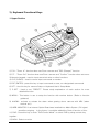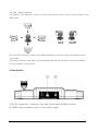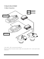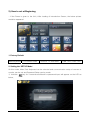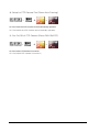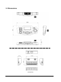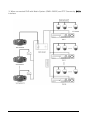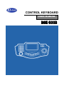
1
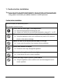
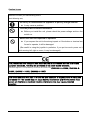
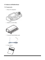
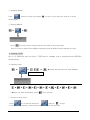
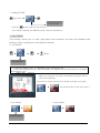
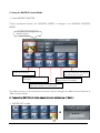
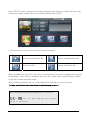
CONTROL KEYBOARD USER MANUAL DCK-500B CONTENTS 1. Caution before installation ……………………………. 3 2. Features & Distinctions ………………………………... 5 1). Components ……………………………………………………………………………. 5 2). Summary & Features …………………………………………………………………. 6 3). Keyboard Functional Keys …………………………………………………………... 7 4). Junction Box …………………………………………………………………………… 9 3. How to Use in Detail ……………………………………. 10 1). Basic Connection ……………………………………………………………………… 10 2). How to set at Beginning ……………………………………………………………… 11 3). Control Mode Setup …………………………………………………………………… 19 1. PTZ Control Mode Setup and Functions ………………………………………….. 21 2. Setup for MATRIX Control Mode …………………………………………………… 27 3. Setup for Direct Mode ……………………………………………………………….. 29 4. Setup for DVR Control Mode ……………………………………………………….. 30 4). Other Detailed Functions …………………………………………………………….. 33 5). OSD Setup Mode ………………………………………………………………………. 33 6). Other Setup Mode ……………………………………………………………………... 34 4. More Cautions and Check Points ……………………. 37 5. Dimensions ……………………………………………… 39 6. SYSTEM Configuration ………………………………… 40 7. General Specifications ………………………………… 43 8. Quick Reference ………………………………………… 45 2 1. Caution before installation Thank you very much for having D-max keyboard. You are strongly required to study this manual before installation. Facing problem or something you don’t understand while using, please consult with your systems installers or service personnel. Caution before Installation Install the unit after you read following advice. Avoid installing in places as below, □ Places with too much high or low temperatures z Extreme temperatures will damage the unit. z Always use it within the recommended temperature range of 0℃ to 40℃ □ Where there are excessive dust, smoke, moisture or humidity. z Using this appliance under such conditions may result in fire, electrical shock or other serious damage □ Where the unit can be blended with all kinds of oil or gas z It may cause the problem if you expose in those conditions. □ Places with vibration or impact z Excessive shock may damage the appliance □ Do not place the appliance in direct sunlight z It may discolor the unit or cause a problem. □ Places with high frequency waves, power cables z Using the appliance under conditions such as electromagnetic waves cause a problem. 3 Caution in use Install the unit after you read following advice. Avoid following acts, □ Do not try to disassemble the appliance or put any foreign element. z It may cause a problem. □ Turn the power off before installation. z Before you install the unit, please check the power voltage and turn the switch on. □ Never have the unit impacted or operated. z If you expose the unit to the strong impact or if the button or terminal are forced to operate, it will be damaged. (Be careful in using the joystick in particular, if you put too much power on it while moving left, right or zoom, it may be damaged) This product has been designed and manufactured in accordance with the harmonized European standards, following the provisions of the below stated directives. Electromagnetic Compatibility Directive 89/336/EEC(EN61000-3-2:1995, EN61000-33:1995, EN50081-1:1992, EN50082-1:1997) This devise complies with part 15 of the fcc rules operation is subject to the following two conditions: (1) This device may not cause harmful interference and (2) This device must accept any interference received including interference that may cause undesired operation 4 2. Features & Distinctions 1). Components ① Body of the Keyboard ② Data Box (Junction Box) ③ Connector Cable (Modular jack) ④ User Manual 5 2). Summary & Features 1. Summary This unit is a multiple CCTV control keyboard enables to control Speed Dome Camera, CCTV Receiver, Matrix System, DVR and so on. You can set up a variety of functions of the speed dome camera and make efficient use of the dome camera for better surveillance by gearing all kinds of sensors. This appliance can be used as a Matrix main(sub) keyboard, CCTV Transmitter main(sub) keyboard at user’s option. This manual is explaining only about controlling CCTV Transmitter, please refer to the matrix manual for the detailed use of D-MAX Matrix system. 2. Features • Locking monitor and camera control. • Convenient control by 5.0 Inch Touch Screen • Controls up to 512 cameras. • Controls maximum 32 monitors (when connecting with matrix, DMX-25632) • Controls maximum 99 DVR • Pan/ Tilt/ Zoom controlled by 3-axis joystick. • Max. 250 Preset widens the surveillance area. • PAN/ TILT Swing (Auto Pan) • 12 Group-Tour • Set and Run the Tour • Set and Run PTZ Trace. • Set up on OSD menu of the camera. • Set and Run Spiral. • Gearing with alarm receiver unit • Control H.264 DVR by Jog-shuttle & LCD Touch Screen • Users with password only can set up the function. • Set-up PTZ Camera, Monitor User’s Authority • Display a live view for one channel on LCD screen 6 3). Keyboard Functional Keys 1. Upper Section 1) F/N : “Zoom In” function when use Zoom camera and “ESC (Escape)” function 2) F/F : “Zoom Out” function when use Zoom camera and “Confirm” function when set menu 3) Numeric keypad : used to input numerical value or other functions 4) CLR (CLEAR) : Used to cancel input command or number. 5) ENT (ENTER) : press this key to input command or save, run designated commands 6) SET : Use this key for camera Setup or Keyboard User’s Setup Mode. 7) P-SET : Used to set “PRESET”. Please study explanation of each section for more detailed function. 8) MENU : This button is use to setup the function with number button. (Refer to function guidance) 9) ALARM : activate or release the alarm when gearing dome camera with ARU (alarm receiver unit) 10) WEB-MONITOR: If an Internet Option Board was installed into Matrix System, DVI signal would be outgoing. In the future, it would be added the Control function of this. 11) DVR : Press this key to enter “DVR Control Mode” or select DVR by using numeric key together. 12) MON : Selects monitor 7 13) CAM : Selects camera 14) Joystick: This joystick is used to control the pan/tilt/ zoom and move the cursor in the OSD menu. 15) Color LCD (Screen): It has many different buttons for each function and supports realtime Video. 16) Sensor: allows to remotely control keyboard with remote controller (soon be released) 17) Jog-shuttle: controls DVR 2. Rear Section 1) RJ-45 Connector: Connection Port with Junction Box & Matrix System 2) VIDEO Input Connector: Input Port for Video signal 8 4). Data Box (Junction box) Set the communication mode to either RS-485 or RS-422 at your option. When communicating in RS-485, the switch(485/422) at both sides should be moved to RS-485. (It is set to RS-485 when we take from warehouse) 485+ 485- NC NC 485+ 485- N C N C GND 422 422 422 422 OUT OUT- IN+ GND 422 IN- 422 422 422 OUT+ OUT- IN+ CAMERA CONTROL 1 RX 485+ 485- N C N C IN- CAMERA CONTROL 2 GND RX 접지 RTS RTS 422 422 422 422 OUT OUT- IN+ IN- SUB KEYBOARD INPUT/OUTPUT TERMINAL OF DATA JUNCTION BOX Camera controls 1: This is the terminal that you can connect with up to 128 speed dome cameras or receivers. (Choose either 485 or 422 communication mode and connect in parallel) Camera controls 2: this is the terminal that you can connect with up to 128 speed dome cameras or receivers. (Choose either 485 or 422 communication mode and connect in parallel) (All together, 256 cameras can be controlled as above connection) Sub keyboard: This is the terminal that you can connect sub-keyboard with when hoping to use sub-keyboard and it does duplex transmission. (Parallel connection is available when using RS485, but if you use RS422 only 1:1 connection is available.) 9 3. How to Use in Detail 1). Basic Connection 485+: 485-: Sub Keyboard Main Keyboard 2 lines (485+, 485-) can be used for data line. (Ground could be of help when earth is stable, but normally 485+, 485- can be used for data connection) 10 2). How to set at Beginning - If the Power is given to the Unit, After loading of Introduction Screen, the below picture would be appeared. 1. Factory Default MAIN Keyboard PTZ Control mode Protocol : D-max 9600 CAM : 001 / DVR : 001 2. Setting the ‘SETUP Mode’ On this mode, Main/ Sub Keyboard can be selected and communication setup of camera or monitor can be set and Password Setup can be made. ① Hold the key for 3 seconds and blank for password input will appear on the LCD as below, 11 ② Input PASSWORD. (Default is 0000) ③ If password is input, Setup mode will show up. SET CAMERA Setup for communication and usage of camera connected to this unit can be set here. ① Touch ‘SET CAMERA’ button on screen, then will go into “SET-UP” mode ② Move the Joystick up/down, left/right and set by turning upper Joystick. ♦ Max. 512 cameras set can be made.. • SELECT CAMERA - Direct: Choose this when PTZ camera is directly connected to keyboard or Matrix.. - DVR mode: Select this mode when PTZ Camera is connected to DVR. - Do not use: It is used to lock the camera so It can not be controlled. 12 • PROTOCOL/SPEED - D-max, Pelco-P, Pelco-D, Samsung Techwin / 9600, 4800, 2400bps can be chosen. ③ Press F/F button : After Save the set-up data and then move to Top Menu Press F/N button : Escape set-up menu and then move to previous menu screen ④ After finish to select Camera, press “SET” button. Then move out to “Control Mode” screen. MONITOR Setup You can set the Monitors here and make it useful or useless from this keyboard. ① Touch ‘SET MONITOR’ button on screen, then will go into “SET-UP” mode • Max. 32 Monitors can be set. • Move to “Monitor No” you like by using Joystick up/ down, left/ right. • You can turn it on/ off by turning the upper Joystick(Head) clockwise or counter clockwise. - USED: Monitor in Use - NOT USE: Monitor not in Use ③ Press F/F button : After Save the set-up data and then move to Top Menu Press F/N button : Escape set-up menu and then move to previous menu screen ④ After finish to set-up, press “SET” button. Then move out to “Control Mode” screen. 13 KEYBOARD SETTING Here you can select the usage of the keyboard. ① Touch ‘SET KEYBOARD’ button on screen, then will go into “SET-UP” mode. ② To select Set-up menu by using Joy-stick “UP” & “ Down” moving, and to change Set-up Value by using Head of Joy-stick “Left” & “Right” turning“. 1) SELECT MAIN/SUB - The unit can be set as Main Keyboard or Sub Keyboard. - Default Value is “MAIN KEY”, but could change to “SUB KEY” by using Head of Joy-stick Left/Right turning. ♦ If select “MAIN / SUB” by SUB KEY, No.2 would be changed to “SUB NUMBER SELECT”. 14 2-1) SET-UP NUMBER OF SUB KEY - If use it for MAIN KEYBOARD, set-up number of allowed SUB KEYBOARD. - Available to allow for number of SUB KEYBOARD up-to 14. 2-2) SELECT TO NUMBER OF USING SUB-KEYBOARD - If use it for SUB KEYBOARD, select to the number of using SUB KEYBOARD. - Available to select the number of SUB KEYBOARD from 1 to 14. ♦ At First, set-up number of Sub-Keyboards on Main-Keyboard, and then select to exact Number of Sub-Keyboard which was connect from no.1 to next step by step. It could be happened an error if the number of Sub-Keyboard is empty Keyboard or select wrong number of Keyboard. 3) SUB COMM TYPE - It works by SCOM1=9600bps / SCOM2=38400bps / SCOM3=115200bps for SUB Interface Set-up. If the Signal Speed is faster, the Reaction Velocity would be faster. But recommend you to set the lower Signal Speed for long distance transmission or poor transmission situation. - In case of SCOM1, available to set maximum 8 number of SUB-Keyboard and can connect with maximum 8pcs of SUB-Keyboard. 4) ALARM TYPE - ARU(Alarm Receiver Unit): With ARU connected, Alarm signal can be received.. - CAMERA: The camera receives Alarm signal by itself. 5) VIDEO MODE : NTSC/PAL - Select the Signal type between NTSC and PAL video signals. - If Video Output is something wrong, please check Video Signal (NSTC or PAL) mode with Keyboard’s Video Mode. They should be same Video Signal. ♦ ex). 1) SELECT MAIN/SUB : MAIN KEY ----------Æ The user wants to use it as Main Keyboard. 2) SELECT SUB KEY Q,ty : 05 ----------Æ It will allow max. 5 Sub keyboards. 3) SUB COMM TYPE : SCOM_MODE3 4) ALARM TYPE : ARU ----------Æ and Alarm signal will be received on ARU. 5) VIDEO MODE : NTSC ----------Æ Video type on Video mode is NTSC. ③ Press F/F button : After Save the set-up data and then move to Top Menu Press F/N button : Escape set-up menu and then move to previous menu screen ④ After finish to set-up, press “SET” button. Then move out to “Control Mode” screen. 15 ALARM On/Off Select to use ARU (Alarm Receiver) which was connected with the Keyboard or Camera Alarm function. • In case “ALARM TYPE” is set as “ARU” on the “3. SET KEYBOARD” ① On SET-UP Menu, Press button on LCD Monitor, then will go into SET-UP mode. • Up to 512 Alarms can be set. • Select ALARM CH ON/OFF. ② Press F/F button : After Save the set-up data and then move to Top Menu Press F/N button : Escape set-up menu and then move to previous menu screen ③ After finish to set-up, press “SET” button. Then move out to “Control Mode” screen. • In case Alarm type is set as ‘CAMERA” on the “3. SET KEYBOARD” • Maximum 512 Alarms can be set. • Move to CAMERA NO. by moving Joystick Up/ Down. • Turning the Joystick head clockwise or counterclockwise, set it to ‘ON’ or ‘OFF’. - on: Enable - off: Disable SELECT DVR Set-Up DVR which is available to control. ① On SET-UP Menu, Press button, then will go into “SELECT DVE” mode. 16 Using Joy-stick “UP” & “ Down” moving • D-max H264 DVR • D-max MPEG4 DVR • Samsung DVR(SRD) After select one which it will control to DVR, then press “F/F” to Save the set-up data and then move to Top Menu ♦ In case of Samsung DVR, it supports some specialized model, so please ask it to supplier at first. DIRECT MODE ◆ Concept of DIRECT Mode ◆ Subject 1 Subject 2 Subject n When Matrix system user set-up and use Preset function on a specific PTZ camera, DIRECT Mode is a shortcut menu. For your information, the user who operates PTZ camera through Matrix system can use the DIRECT mode. This mode is most useful to keep on eye on Guard Posts and Casino. On SET-UP Menu, Press button, then will go into “DIRECT MODE SET”. 17 TABLE No. – it’s available to set from 1 to 999 numbers. User can set Camera number & Preset number by Joy-stick. Move the Joy-stick UP/Down, Left/Right and set by turning upper head of Joy-stick. SYSTEM SETUP This is Factory Re-Set, Set-Up new Password, and Change Multi-language (Third country language) menu. ① On SET-UP Menu, Press button, then will go into “SYSTEM SETUP” mode. 1) Change Password Available to change the Password of Keyboard. ① Select ”1) CHANGE PASSWORD” and using Joy-Stick to move “Left” or “Right”, then will find a window to input the new Password. ② Input your expected Password (4 words of numeral) and repeat it again, then will find a message of “CHANGE PASSWORD” on screen. **** ③ After Change Password, press F/F button to save the new Password and then move to Top Menu. 2) FACTORY RESET All Setup value will be changed into “DEFAULT”. ① Select ”2) FACTORY RESET” and using Joy-Stick to move “Left” or “Right”, then press ”F/F” button. ② Show “Rebooting…” message on screen, and then all set-up values would be changed to factory default values and would be boot up the Keyboard. 3) LANGUAGE Change UI (User Interface) Language. ① You can change the language when you select “3) LANGUAGE”. * Selectable Language: KoreanÆJapaneseÆRussianÆPolishÆEnglish ② After select language what you want, press “F/F” button to save this selection. Then the system would be restarted. 18 3). Control Mode Setup You will come to know more details about PTZ, MATRIX, DIRECT, DVR mode on this chapter. Basic Operation Interface ① ② ③ ④ ⑤ ⑥ ⑦ ⑧ ① MAIN/SUB Keyboard Indicator - It indicates on PTZ/ MATRIX/ DVR mode if the unit is main keyboard or sub keyboard. (It also shows if the unit is 1st, 2nd or 16th keyboard. - Please refer to “2. SETTING the SETUP Mode” for main / sub keyboard setup. ② Indicator for Mode status - It indicates if the current status is in PTZ, MATRIX or DVR mode. ③ Protocol Indicator - The current protocol set is indicated. ④ Indicator of communication status 19 Sub keyboard 1~14 TX/RX Main keyboard Matrix Alarm - This section indicates connection status of MAIN/SUB KEYBOARD and signals of MATRIX, TX, RX. • MAIN KEYBOARD: If the unit is set as main keyboard, it blinks. • MAIN/SUB KEYBOARD 1~14: If you have set SBU KEYBOARD, it will be seen in red. (The first bar would blink when the unit is set as MAIN Keyboard.) • MATRIX: If the unit is connected with MATRIX, it flickers. • TX/ RX: They blink when there are TX/ RX signal. • ALARM : This Light would be flickering when an Alarm signal incomes. ⑤ It indicates Active or Inert status of ALARM. Press button after ALARM is turned on and it will turn into RED and Alarm will be activated. ⑥ Button for CONTROL MODE conversion - Whenever this button is pressed, it will be converted from PTZ ▶ MATRIX rotation. ♦ Press button, then will go into DVR mode. Press state button like as above on LCD screen, then will go into PTZ or MATRIX mode again. ♦ If the Keyboard Controller is “SUB-Keyboard” mode, it doesn’t support “DIRECT MODE”. ⑦ Input value of Monitor, Camera, DVR and other commands will appear in letters. ⑧ Each CONTROL MODE is shown. 20 1. PTZ Control Mode Setup and Functions ① Set-Up PRESET This function allows the camera to automatically move to the designated positions and the keyboard can program up to 250 preset positions for each camera. The memorized preset position can be replaced with new preset position (new value). ① Setting PRESET By using Joystick, move the camera to which you like to set and press ¨ ¨ ~ ② Calling Preset Positions you previously set ¨ ~ ③ Individual deletion of PRESET 000 Clear Function ! If you hold the button for 3 seconds, a message, ‘Clear Function!’ will appear and it will become CLEAR Mode. Delete Presets you want and get out of the ‘CLR’ Mode by pressing Press button for 3 seconds until you hear a beep and press 21 button again. ~ ¨ ¨ ④ Deleting All Presets Hold the button for 3 seconds and you hear a beep. Then press ¨ Ex). Delete Preset No.5 and No.6 (hold button for 3 seconds) ¨ ¨ ¨6¨ ¨ ※ Maximum quantity of PRESET positions input may be subject to the features of camera or receiver. ② Set-Up SWING You may select only 2 preset positions memorized from what you had set at preset mode(in horizontal or vertical) and exercise surveillance repeatedly over the memorized areas. The keyboard can program either Pan Swing or Tilt Swing ① Set Swing mode ¨ ¨ (TILT) ¨ (PAN) or ¨ starting Swing Mode : 1=Pan, 2=Tilt ¨ ¨ Swing Time? 1-128sec mode. (Push No. ¨ ~ ¨ ending ~ preset No Swing End No.? ¨ moving speed dwell time ※ Pressing preset Swing Start No.? ¨ ~ ¨ ~ Swing Speed? 1-64/sec button, ‘Camera Set Function’ in red will appear at the bottom and it means “SET” key if you want to cancel SET mode) ※ Swing Time is DWELL TIME that the camera stays before camera moves from a starting position to ending position and it can be set from 1~127 seconds. ※ Moving speed is that the camera moves from starting point to ending point. Maximum speed is 64.. ※ Set PAN SWING to No.1, TILT SWING to No.2. Please be sure to place them in straight line in order to protect malfunction. (Pan in horizontal line, Tilt in perpendicular.) 22 ② Practice Swing (PAN) or (TILT) ¨ ③ Stopping Swing Just press to stop it. (It will go back to operation after few button or touch the Joystick seconds.) ※ When it is being used as ‘Auto Pan’ of CCTV Receiver, you are required to push ‘SWING’ key and you can’t stop it with Joystick. ③ Set-Up GROUP Maximum 12 Preset Points can be set in one GROUP. You can make up to 12 GROUPs setting speed, dwell time. ① Inputting GROUP ¨ ¨ ¨ ~ ¨ Press GROUP No. Group No.? 1-12 ¨ ~ ¨ Press PRESET No. Preset No.? 1-250 ¨ ¨ ~ ~ ¨ Moving Speed Move Speed? 1-64 ¨ (Preset No.~ Repeat) Dwell Time: The time that the camera stays from preset point to the next point. Dwell Time? 1-128sec Preset No.? 1-250 ※ In order to finish one GROUP and set other GROUPs, press key after you finish procedures of inputting PRESETs. ※ After you finish all inputting procedures, press ② Executing GROUP ~ ¨ 23 key and enter Normal Mode. ③ Stopping GROUP Press button or touch the Joystick to stop. (If you stop it by Joystick, It will be running again. ④ Deleting GROUP ¨ ¨ All Group Clear? ※ Press key until you hear a beep and put your hand off from the button. There is no way to delete each GROUP respectively and all GROUPs will be deleted at a time. ④ Setting TOUR Up to 12 GROUPs can be tied in TOUR and it enables you to execute those GROUPs consecutively. ① Inputting TOUR ¨ ¨ ¨ ~ ¨ Repeat the procedure for other GROUPs. Select GROUP (1~12) Group No.? 1-12 ¨ ¨ ¨ ¨ ¨ ¨ When you finish all inputting, press ¨ ¨ ¨ ¨ key at the last. ② Execute or Stop TOUR Touch 버튼 key to execute and touch again or to stop. If it is stopped by Joystick, TOUR function will resume in a few seconds. 24 ¨ ¨ ③ Deleting TOUR ¨ (for 3secs.)¨ All Tour Clear? button until you hear a beep. ※ Hold the ※ If the TOUR is deleted, the GROUP tied in it will also be deleted. ⑤ Set TRACE This function allows you to track (play back) the movement the user had operated with panning, titling, zooming for more than 95 seconds. ① Set TRACE ¨ ¨ ¨ Move Trace Set ENT? ※ To Set-Up & Delete Trace, it’s available to set on Keyboard only. ※ If Trace has already been set, ‘Sorry Not Blank!’ will appear and you will need to set up again after deleting Trace. 삭제후 재설정 하십시오 ※ While you move the Joy-stick it saves and its progress will be seen as left drawing. If you wish to stop to set-up Trace during moving the Joy-stick, ¨ ② Run TRACE touch buttons like as left, then save it ③ Stop TRACE ¨ ¨ Trace On/Off? 25 ④ Clear memorized TRACE ¨ (for 3secs.)¨ * Please study camera manual for more details about Trace function. ⑥ VIDEO mode If you touch button when the video line is input, it will be converted to Full screen Display Mode. When speed dome is connected, OSD menu appears (1+MENU) CCTV Receiver auto (2+STATUS) PTZ information (3+STATUS) Go back to previous Menu . ⑦ Turning ON/OFF the Camera, Light Power Select a receiver (camera) you wish to ON/OFF ¨ ~ ① Camera Power ¨ ¨ or ② Light Power ¨ ¨ or ③ AUX Power ¨ + ¨ or + ¨ or ※ This function is only subject to CCTV Receiver. 26 test 2. Setup for MATRIX Control Mode ① Enter MATRIX CONTROL Touch conversion button for CONTROL MODE to change it into MATRIX CONTROL MODE. The status LED changes into ‘MATRIX MODE’ Functions for Cameras’ Power and Switcher Matrix SET-UP button: Touch and input Password then will go into Matrix SET-UP mode. RUN: Videos not in move are switching. VIEW: When need to stop Matrix monitor live display. HOLD: Use this button to see videos when the camera is in ‘RUN mode’ Like above picture, all those buttons at bottom will be changed into Matrix Control Buttons at ‘Matrix Control Mode.’ (* Please study MATRIX instruction manual for more detailed use of Matrix.) ② MATRIX SET mode ¨ 27 **** Press “SETUP” button, and input the correct Password, then will go into Matrix Set-Up mode. (Password is same as Main Set-Up, the Default Password is “0000”) If correct password is input, the menu will be converted as above. Entering ‘AUTO SELECT SET‘ Entering ‘ALARM/PRESET SET’ Entering ‘ID SET’ Entering ‘TIME/DATE SET’ When set Matrix Set-Up menu, the color of touched button would be changed and it would be activated. After finish to set Matrix Set-Up menu, press same relevant button of Menu, so the Set-Up data would be saved. After complete finished to set-up, press state button and then move to Top menu. (*Please consult Matrix Instruction Manual for detailed setup of Matrix.) NOTE: Press below buttons when MATRIX OSD is not shown. + press this button and then press expected Monitor No. + ENT button. 28 3. Set-Up DIRECT Mode ① How to go into DIRECT Mode Press button of CONTROL MODE Conversion, then select DIRECT Mode. Only Main Keyboard Controller supports DIRECT Mode. 001 001 000 000 ② Practice of DIRECT Mode ① (Number of Monitor) + MON ¨ Select Matrix monitor number which user wish to keep on eye on. The camera which was related ¨ ② Numbering button (Number of TABLE) + with TABLE display image on the monitor and then Preset function would be performed. 29 4. Setup for DVR Control Mode ① Setup to enter DVR mode(D-max DVR) Press button on screen or Press state button, then will go into DVR mode. Status Indicator will be converted to ‘D-max DVR’. ※ When select DVR mode, the DVR mode has same set-up as “SETUP-5.SELECT DVR”. Call Menu, Goes to previous status in menu In case of system error, the error icon appears on screen with beep sound. Press “ENTER” button, stopping beep sound and display Error list. Sequence sprit screen in live automatically. When press button one by one, it show Split Screen setting one by one. Display recoding image ex.)1,2,3,4chÆ5,6,7,8chÆ9,10,11,12ch… Switch Full or Quad view, Max quad of screen according to DVR, Press direction button in 9ch, 16ch DVR Start to record image according to setting schedule. Press button to start schedule recording in emergency record mode. • 9 Channel DVR : Click “SPLIT” Button -> Revert to 9 quad mode • 16 Channel DVR : Click “SPLIT” Button -> 30 Revert to 16 quad mode In case of emergency, press “EMERGENCY” button to start recording forcibly regardless of the recording schedule with setting resolution and recording frame in all channel. Avoiding HDD waste, have to change to “Schedule recode” mode Auto Sequence each channel will be conducted in Live according to setting dwell time between camera. Set [MENU]-> [DISPLAY] -> [Auto Sequence] ※ Control DVR by Keyboard, when user may requested input DVR password by Keyboard, press input password by numeral buttons( ~ Ex). If Password is “1234567”, press ) and then press Æ + button one by one. + Æ…Æ + buttons one by one. When try to control PTZ camera or Set-Up mode and if it doesn’t work anything, please check (SETUPÆ1.CAMERA SET) is DVR mode or not. On DVR mode, PTZ camera should be connected with DVR and CAMERA NO.1~16 should be selected to DVR Mode, because only 9CH/16CH DVRs work with PTZ camera. In case of H.264 DVR, DVR ID should be same as 는 DVR Remote Controller’s ID. So please check the ID in Front LCD of DVR. ※ Please consult the DVR instruction manual for DVR OSD Menu or other related information in detail. 31 ② Set-Up MPEG4 DVR mode Status Indicator will be converted to ‘MPEG4 DVR” Starts/ Stop Recording Enter DVR OSD MENU Display recoding image Video will be changed into 4/ 9/ 16CH Playback/ Pause at Playback mode Video automatically switches or stops This button is used as a function key in ‘Live view’ and ‘Enter’ in other menus or search mode To enter PTZ mode Move to upper menu or cancel the command ※ Please consult the DVR instruction manual for DVR OSD Menu or other related information in detail.. 32 4) Other Detailed Functions Select Camera and ~ ! Press any camera number (1~255) you wish to control Select Monitor ~ Select DVR ~ key ! Press any monitor number (1~32) you wish to control and key ! Press any monitor number (1~99) you wish to control and key 5). OSD Setup Mode 1. Entering OSD Menu It brings in camera own menu and the menu will appear with beep sound on monitor if you input as below ¨ 2. Control OSD Menu The cursor will be flickering on monitor (waiting for command) Move the Joystick right/ left, up/ down and put the cursor as desired. 3. Getting out of OSD Menu ¨ Do as above and the menu on the monitor will disappear and the OSD menu will be released.. ※ This function can be used in the speed dome camera only. ※ Please refer to the camera instruction manual for more detailed usage of OSD menu. 33 6). Other Setup Mode ① Spiral Function This function is supported only on speed dome cameras, the fixed panning speed and tilting speed are operated at the same time that can make spiral surveillance ¨ ¨ or Spiral SEQ On/Off? ※ This function can be used in the speed dome camera only. ② Camera Remote Reset Initialize the camera or receiver in case they have a problem . ¨ ~ ¨ ¨ ¨ Camera Remote Restart? ※ This function can be used in the speed dome camera only. ③ Keyboard Buzzer On/Off Turn on/ off the buzzer of the keyboard. Buzzer sound On/Off? ¨ ④ Converting Up/Down Convert the control of up/ down, for instance, If you move the joystick down, it will go up. Up Down Change? ¨ ⑤ Converting Left/ Right Convert the control left/ right, for instance, if you move the joystick left, it will move right ¨ Left Right Change? 34 ⑥ Convert the voltage of Lens Control When the movement of Zoom Lens is too slow or fast, you can change the voltage to adjust the proper speed ¨ Lens : 1=6V,2=9V,3=12V ¨ ※ Article ④~⑥ are for DRX-500, DRX-502A and SRX-100B(CCTV Receivers). ⑦ Alarm Relay On/Off Alarm Relay inside Speed Dome can be turned On/ Off. Æ + or • ‘Relay On’ or ‘Relay Off’ will be shown on the screen. ⑧ Control Joystick Speed (Joystick Speed (0,1) 0=MAX) After decreasing its speed you may control the dome more precisely. Æ + or • 0: Default •1: Cut down Speed ⑨ Auto RTS On/Off If user wish to connect Keyboard with other transmitters in parallel to control PTZ camera, User should set “ON” of this menu. + Æ or On: Sub Data is come through the Main Keyboard and it is working reliably.(Default) Off: To control PTZ Camera by the Keyboard with other Transmitters (DVR or another Keyboard) which were connected in parallel. 35 ⑩ Setup for PTZ Camera Fan (Dome Auto Fanning) + Æ or On: Fan inside the PTZ Camera can be automatically operated. Off: Fan inside the PTZ Camera can be manually operated. ⑪ Fan On/Off of PTZ Camera (Dome FAN ON/OFF) + Æ or On: Fan inside PTZ Camera is turned on. Off: Fan inside PTZ Camera is turned off. 36 4. More Cautions and Check Points Cautions in Use z Do not give a power to the unit in the process of installing. z It is recommended that the unit be installed in a well-ventilated place since the operating range is 5°C~40°C. z Do not expose the unit to extreme impact, which may cause serious damage. z Avoid installing in the direct rays of the sun. z Never install the unit in place with strong magnetic, an electric or a radio wave which cause a problem in communication. z Be careful not to connect wrong cable or line while installing. z Never operate the unit until the buzz(beep sound) goes off after turning on the power. z Give a power to the unit after you check the insulated wire connected outside. z Always use the keyboard cable provided with the keyboard. z Do not give too much strength to the joystick while controlling. 37 Simple Trouble Shooting Please check out followings when you face some problems while installing or using. Problem Check Point Is The power can’t be brought. The camera can’t pan/ tilt. It’s not working in Subkeyboard. the Reference connection between Make sure to connect the Modular keyboard and junction box correct? cable.(RJ45) Is Be sure to plug the power supply into the Power sources being supplied now? the consent. Did you press the camera number Try again after pressing CLR button. correctly? Is the RX address the same as Check out again the DIP Switch of the Camera address? RX. Hasn’t the sub-keyboard address Check setup of main/ sub-keyboard been repeated as you initially set? Has the data cable been again. Check the connection and polarity of connected correctly? the data cable. Have you set Preset positions at Set Preset position and try again. Preset movement is Preset mode? not working. Does the camera support Preset Press number 3 and STATUS key and function? check out the camera model. Have you set it on Main keyboard? It can’t be set on Sub-keyboard. Have you set off the all Alarm If you set it off it can’t be on. Please channels? refer to the Alarm setup page. There is an error when setting motion. Alarm can’t be on. 38 5. Dimensions Junction Box 39 6. SYSTEM Configuration 1. When the keyboard is directly connected to PTZ Camera. 2. When connected with Matrix System (DMX-25632) and PTZ Camera 40 3. When connected DVR with Matrix System (DMX-25632) and PTZ Camera by DATA interface 41 4. When connected DVR with Matrix System (DMX-25632) and PTZ Camera by VIDEO interface 42 7. General Specifications 1). Product Standard Classification Output Signal Communication speed Specification ● RS – 422 ● RS – 485 ● Speed 9,600, 4,800, 2,400BPS, No parity, 8Bit data, 1Bit stop ● Control Pan/Tilt /Zoom lens ● Camera power On/Off , Light power On/Off , AUX On/Off Operation ● Alarm On/Off , Preset set/clear ,OSD ● Control Matrix ● Main / Sub keyboard ● Display : LCD Display ( The way to select Menu ) Operating Status (Display) ● Input ? : Number input by Key can be outputted. ● Camera : If camera is called input data can be outputted.(1~256) ● Monitor : If monitor is called input data can be outputted1-32) ● When pressing key : Make a buzz sound for about 0.5seconds. Sound in Use ● When inputting wrong data : Make a buzz sound for 3 times. ● If alarm is sounded when Alarm is on : it keeps making a warning beep sound Accessories ● Body of keyboard -1- ● Modular cable(RJ-45cable with 10M long) -1- ● Data junction box -1- ● DC 12V 1.5A Adaptor 2). Controller Specification -1- 3).Junction Box specification ITEM Specification ITEM Specification In/ Output Terminal Modular jack In/output terminal Modular jack Communicate with Junction Box TTL Power supply DC 12V, 1A Adapter Operating Temperature 0∼40。C Camera Control RS-485/RS-422 Storage Temperature -5∼55°C Operating temp. 0∼40。C Storage temp. -5∼55°C Operating Humidity 10∼75% Operating humid. 10∼75% Storage Humidity 10∼95% Storage humidity 10∼95% Dimension 390(L)×191(W)×102(H) Dimension 109(L)×66(W)×27(H) Weight Approx. 0.9kg Weight Approx. 0.3kg 43 4). Power Supply Voltage : DC 12V (±10%) Current : 1.5A (min) 5). Camera control interface ITEM 6). Constitution of pin between controller and junction box (Modular Jack) Specification Pin no. Controller ↔ Junction box Asynchronous Serial Interface 1 RX-TXD 1 Start bit 2 B+12V 3 RX-RXD 4 RX-RTS 5 GND 6 SK-TXD 7 SK-RTS 8 SK-RXD Synchronization / 8 Data bit System& word length No parity 1 Stop bit 11 Byte command Signal polarity Mark logic "1" Space logic "0" Transmit direction Half duplex Transmit speed 9600 bps 44 8. Quick Reference Operation Function Function Input Main Sub Keyboard [1-64] + [MON] Select Monitor ◎ ◎ Keyboard [1-512] + [CAM] Select Camera ◎ ◎ Power supply ON + [SET] Setting Controller ◎ ◎ [SET] Start Setup mode for Preset ◎ ◎ [SET]+[Joystick Stop]+[Keypad 1~128]+[PST] Run Preset, Preset movement [Preset No]+[PST] [CLR+3sec]+[Keypad 1~128]+[PST]+[ENT] Deleting each Preset [CLR+3sec]+[PST]+[ENT] Clear all Preset Positions [SET]+[SWING] Start Setup mode for Swing [1/2]+[ENT] Select Pan or tilt swing [Keypad1~128]+[ENT]+[Keypad 1~128]+ Select 2 different preset positions [ENT] Set Swing Speed [Keypad 1~127]+[ENT] Set dwell time [Keypad 1~64]+[ENT] Run Pan or tilt swing [1/2]+[SWING] Stop Swing [SET]+[GROUP] Start setup mode for Group [Keypad 1~6]+[ENT] Select Group number [Keypad 1~64]+[ENT] Select Preset point [Keypad 1~64]+[ENT] Set moving speed between Preset positions [Keypad 1~127]+[ENT] Set Dwell time [SET] Confirm Input value [Keypad 1~12]+[GROUP] Run Group Surveillance [GROUP]/Joystick Stop Group Surveillance [SET]+[TOUR] Start setup mode fro Tour [Keypad 1~12]+[ENT]←repeat Set Tour repeatedly [SET] End setup for Tour [TOUR] Run Tour Sequent surveillance [C/P] + [ON/OFF] Turn on/ off CCTV CAMERA power ◎ ◎ [L/P] + [ON/OFF] Turn on/ off CCTV LIGHT power ◎ ◎ 45 Executable ◎ NotConfigurable Executable ◎ NotConfigurable Executable ◎ NotConfigurable [7]+[MENU]+[ON] Run Spiral function [7]+[MENU]+[OFF] Stop Spiral function [Keypad〕 ◎ Camera Reboot ◎ [11] + [MENU] + [ENT] Converting Up / Down Mode ◎ [12] + [MENU] + [ENT] Converting Left / Right Mode ◎ [15] + [MENU] + [1/2/3] + [ENT] Converting Lens Voltage, 6V / 9V / 12V ◎ Hold down [CLR] key for 3 seconds Enter CLEAR MODE [PRESET Number 1~64] + [PST] Delete Preset position one by one ◎ [PST] + [ENT] Clear all Preset positions ◎ [GROUP] + [ENT] Clear all Group [TOUR] + [ENT] Clear Tour Sequence [Sensor Number 1~255] + [ALARM Delete Alarm one by one [ALARM] + [ENT] Clear all Alarms ◎ [Monitor Number 1~64] + [MON] Delete Monitor one by one ◎ [[MON] + [ENT] Clear all Monitors [1~512]+[CAM]+[10]+[MENU]+[ENT] ◎ ◎ ◎ ◎ ◎ ◎ 47