1
EF5XX-Series Solid State Disk Drive
User Guide
EK–EF5XX–UG–001
Digital Equipment Corporation
November 1992
Copyright © Digital Equipment Corporation 1992
The information in this document is subject to change without notice and should not be construed as a
commitment by Digital Equipment Corporation. Digital Equipment Corporation assumes no responsibility
for any errors that may appear in this document.
The software described in this document is furnished under a license and may be used or copied only in
accordance with the terms of such license.
No responsibility is assumed for the use or reliability of software on equipment that is not supplied by
Digital Equipment Corporation or its affiliated companies.
Restricted Rights: Use, duplication, or disclosure by the U.S. Government is subject to restrictions as set
forth in subparagraph (c)(1)(ii) of the Rights in Technical Data and Computer Software clause at DFARS
252.227-7013.
All Rights Reserved.
Printed in U.S.A.
FCC NOTICE: The equipment described in this manual generates, uses, and may emit radio frequency
energy. The equipment has been type tested and found to comply with the limits for a class A computing
device pursuant to Part 15 of FCC Rules, which are designed to provide reasonable protection against
such radio frequency interference when operated in a commercial environment. Operation of this
equipment in a residential area may cause interference, in which case the user at his own expense may
be required to take measures to correct the interference.
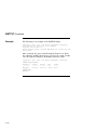
German Noise Declaration: The following information is provided to meet the German Noise
Declaration Decree (part of the German Equipment Safety Law).
English:
September 18, 1992
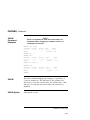
--------------------------------------------------------------------Acoustics - declared values per ISO 9296 and ISO 7779:
Sound Power Level
L
,
Sound Pressure Level
B
L
, dBA
pAm
(operator position)
WAd
Product
EF51/2R-AA/F
BA430/440 +
3xEF51/2R
R400X +
7xEF51/2R
Idle
Operate
Idle
Operate
4.4
4.5
34
35
5.6
5.6
39
39
5.6
5.6
40
41
[Current values for specific configurations are available from Digital
representatives. 1 B = 10 dBA.]
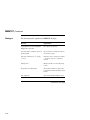
--------------------------------------------------------------------German:
September 18, 1992
--------------------------------------------------------------------Schallemissionswerte - Werteangaben nach ISO 9296 und ISO 7779/DIN EN27779:
Schalleistungspegel
L
, B
WAd
Product
EF51/2R-AA/F
BA430/440 +
3xEF51/2R
R400X +
7xEF51/2R
Leerlauf
Schalldruckpegel
L
, dBA
pAm
(Bediener position)
Betrieb
Leerlauf
4.4
4.5
34
Betrieb
35
5.6
5.6
39
39
5.6
5.6
40
41
[Aktuelle Werte für spezielle Ausrüstungsstufen sind über die Digital
Equipment Vertretungen erhältlich. 1 B = 10 dBA.]
---------------------------------------------------------------------
The following are trademarks of Digital Equipment Corporation: DEC, DECmailer, DECservice, DSA,
DSSI, EF, KA640, KFQSA, MicroVAX, MSCP, Q-Bus, RF31, RF72, SERVICenter, TMSCP, ULTRIX, VAX,
VAXsimPLUS, VMS and the Digital logo.
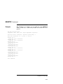
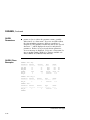
Contents
Preface
1
General Information
Overview . . . . . . . . . . . . . . . . . . . . . . . . . . . . . . . . . . . . . . . . . . . . . . . .
EF5XX ISE Specifications . . . . . . . . . . . . . . . . . . . . . . . . . . . . . . . . . . . .
Shipping Contents/Related Documents . . . . . . . . . . . . . . . . . . . . . . . . . .
2
Installation Overview
Introduction . . . . . . . . . . . . . . . . . . . . . . . . . . . . . . . . . . . . . . . . . . . . . .
Installing into the BA400-Series Enclosure . . . . . . . . . . . . . . . . . . . . . . .
Installing into the SF7X Enclosure . . . . . . . . . . . . . . . . . . . . . . . . . . . . . .
3
2–1
2–2
2–8
Controls and Indicators
Introduction . . . . . . . . . . . . . . . . . . . . . . . . . . . . . . . . . .
BA400-Series Controls and Indicators . . . . . . . . . . . . . . .
Changing the DSSI Node ID Plugs (BA400-Series OCPs)
SF7X Controls and Indicators . . . . . . . . . . . . . . . . . . . . .
EF5XX ISE Controls and Indicators . . . . . . . . . . . . . . . . .
4
1–1
1–7
1–12
.
.
.
.
.
.
.
.
.
.
.
.
.
.
.
.
.
.
.
.
.
.
.
.
.
.
.
.
.
.
.
.
.
.
.
.
.
.
.
.
.
.
.
.
.
.
.
.
.
.
.
.
.
.
.
.
.
.
.
.
3–1
3–3
3–5
3–6
3–8
.
.
.
.
.
.
.
.
.
.
.
.
.
.
.
.
.
.
.
.
.
.
.
.
.
.
.
.
.
.
.
.
.
.
.
.
.
.
.
.
.
.
.
.
.
.
.
.
.
.
.
.
.
.
.
.
.
.
.
.
.
.
.
.
.
.
.
.
.
.
.
.
.
.
.
.
.
.
.
.
.
.
.
.
.
.
.
.
.
.
.
.
.
.
.
.
4–1
4–4
4–9
4–10
4–14
4–17
4–18
4–19
Local Programs
Introduction . . . . . . . . . . . . . .
How to Access Local Programs
Descriptions of Local Programs
DRVEXR . . . . . . . . . . . . . . . .
DRVTST . . . . . . . . . . . . . . . .
HISTRY . . . . . . . . . . . . . . . . .
DRINIT . . . . . . . . . . . . . . . . .
BATTST . . . . . . . . . . . . . . . . .
..
.
..
..
..
..
..
..
.
.
.
.
.
.
.
.
.
.
.
.
.
.
.
.
.
.
.
.
.
.
.
.
.
.
.
.
.
.
.
.
.
.
.
.
.
.
.
.
.
.
.
.
.
.
.
.
.
.
.
.
.
.
.
.
.
.
.
.
.
.
.
.
.
.
.
.
.
.
.
.
.
.
.
.
.
.
.
.
.
.
.
.
.
.
.
.
.
.
.
.
.
.
.
.
.
.
.
.
.
.
.
.
.
.
.
.
.
.
.
.
.
.
.
.
.
.
.
.
.
.
.
.
.
.
.
.
.
.
.
.
.
.
.
.
.
.
.
.
.
.
.
.
Contents–iii
MEMTST . . . . . . . . . . . . . . . . . . . . . . . . . . . . . . . . . . . . . . . . . . . . . . . .
PARAMS . . . . . . . . . . . . . . . . . . . . . . . . . . . . . . . . . . . . . . . . . . . . . . . .
5
Data Retention System
Introduction . . . . . . . . . . . . . . . . . . . . . . . . . . . . . . . . . . . . . . . . . . . . . .
EF5XX Data Retention Description . . . . . . . . . . . . . . . . . . . . . . . . . . . . .
Battery Subsystem Parameters . . . . . . . . . . . . . . . . . . . . . . . . . . . . . . . .
6
4–23
4–27
5–1
5–2
5–7
Troubleshooting Procedures
Performing Troubleshooting Procedures . . . . . . . . . . . . . . . . . . . . . . . . .
6–1
Index
Figures
1–1
2–1
2–2
2–3
2–4
2–5
3–1
3–2
3–3
EF5XX-Series ISE–Front and Rear Views (Brackets shown are used only
for certain installations.) . . . . . . . . . . . . . . . . . . . . . . . . . . . . . . . . . . . . . .
Removing the Plastic Skid Plate (AF or AA version only) . . . . . . . . . . . . .
Installing the ISE in the Enclosure (RF and RZ front panels shown for
reference.) . . . . . . . . . . . . . . . . . . . . . . . . . . . . . . . . . . . . . . . . . . . . . . .
Removing the Top and Bottom Brackets (AF or AA version only) . . . . . . . .
Inserting the Wedges on the EF5XX ISE . . . . . . . . . . . . . . . . . . . . . . . . .
The SF7X Enclosure . . . . . . . . . . . . . . . . . . . . . . . . . . . . . . . . . . . . . . . .
BA400-Series OCP (front panel) for DSSI ISEs . . . . . . . . . . . . . . . . . . . .
SF7X Controls and Indicators . . . . . . . . . . . . . . . . . . . . . . . . . . . . . . . . .
Drive Module Switch and LED Locations . . . . . . . . . . . . . . . . . . . . . . . . .
Contents–iv
1–5
2–4
2–6
2–10
2–12
2–14
3–3
3–6
3–9
Tables
1–1
5–1
5–2
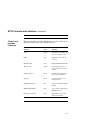
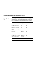
EF5XX Series Performance Features . . . . . . . . . . . . . . . . . . . . . . . . . . . .
Battery Maintenance Errors . . . . . . . . . . . . . . . . . . . . . . . . . . . . . . . . . . .
BSS Parameter Definitions . . . . . . . . . . . . . . . . . . . . . . . . . . . . . . . . . . .
1–6
5–3
5–7
Contents–v
Preface
Introduction
In This Guide
This guide introduces the EF5XX-series solid state disk drive
and describes the installation and operating procedures.
Intended
Audience
This guide is intended for the EF5XX disk drive user.
Chapter 1
‘‘General Information’’ describes the different variations of the
EF5XX solid state disk drive including the data retention
system, the Digital Storage System Interconnect (DSSI)
bus function, performance features, specifications, shipping
contents, and related documents.
Chapter 2
‘‘Installation Overview’’ describes how to prepare the EF5XX
disk drive for installation and how to install the EF5XX into
the BA400-series system and SF7X storage enclosures.
Chapter 3
‘‘Controls and Indicators’’ describes the controls and indicators
used to operate the EF5XX disk drive and how to assign the
DSSI node ID.
Continued on next page
vii
Introduction, Continued
Chapter 4
‘‘Local Programs’’ describes how to access local programs
through the:
VMS system and the console by using the SET HOST/DUP
command
MicroVAX Diagnostic Monitor (MDM)
Chapter 5
‘‘Data Retention System’’ discusses integrated data retention
system features including battery testing and monitoring.
Chapter 6
‘‘Troubleshooting Procedures’’ describes the internal self-tests
the EF5XX Integrated Storage Element (ISE) conducts and
what to do if the EF5XX disk fails to operate correctly.
Conventions
The term EF5XX refers to the EF51R, EF52R, or the EF53 solid
state disk drive.
viii
Chapter 1
General Information
Overview
In this Chapter
This chapter includes:
EF5XX-series solid state disk drive description
Using the EF5XX disk drive
EF5XX options
Data retention system description
Digital Storage System Interconnect (DSSI) bus function
Integrated Storage Element (ISE)
EF5XX-Series ISE
Drive performance features
Drive specifications
Shipping contents
Related documents
Continued on next page
1–1
Overview, Continued
Description
The EF5XX series is Digital Equipment Corporation’s first
generation of solid state disk drives packaged in a full-height,
5¼-inch form factor. These DSSI ISEs supply highly reliable
data storage using semiconductor memory as the storage media.
Like all DSSI ISEs, the EF5XX-series disks communicate with
the host using Digital Storage Architecture (DSA) and Systems
Communications Architecture (SCA) protocols such as the Mass
Storage Control Protocol (MSCP). EF5XX-series disk drives
retain the familiar packaging, control panel, diagnostics, and
utilities of the RF series ISEs.
Continued on next page
1–2
Overview, Continued
Using the
EF5XX
You can use the EF5XX-series ISEs with these VAX family
systems:
VAX4000
VAX6000
VAX7000
VAX10000
EF5XX
Options
These are the EF5XX ISEs covered in this guide and their
formatted storage capacities:
EF51R, 107 megabytes
EF52R, 205 megabytes
EF53, 267 megabytes
Data
Retention
System
Description
The EF51R and the EF52R ISEs provide non-volatility of data
by a data retention system including:
Power sensing logic
An internal winchester magnetic disk drive
A battery to power the EF5XX while dumping data to the
winchester disk
For more detailed information on data retention, refer to
Chapter 5.
Continued on next page
1–3
Overview, Continued
DSSI Bus
Function
The DSSI bus is a logical equivalent to the CI bus used on
larger Digital systems. The DSSI bus is used with low-end and
mid-range VAX systems.
The DSSI bus is a 50-conductor cable that allows one or more
hosts to communicate directly with storage devices. The hosts
and devices communicate through the SCA protocols. As many
as eight nodes (integrated storage elements and adapters) can
connect to one DSSI bus.
The DSSI bus located:
Inside an enclosure may be a flat ribbon cable or a round
bundle of twisted pairs
Between enclosures is a shielded, round cable
approximately one-half inch in diameter
ISE
An ISE is a DSSI device that contains an:
Embedded, intelligent controller
On-board Mass Storage Control Protocol (MSCP) server
Each ISE executes commands and transfers data independently
of other ISEs attached to the DSSI bus. Commands and data
are transferred over the DSSI bus in small packets, allowing
multiple ISE transfers to simultaneously complete successfully.
Continued on next page
1–4
Overview, Continued
EF5XX-Series
ISE
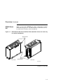
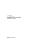
Figure 1–1 shows the EF5XX-series disk, a full-height, 5-¼inch,
fixed-disk storage device. Its dimensions are 8.26 cm (3.25 in)
by 14.60 cm (5.75 in) by 20.32 cm (8.00 in).
Figure 1–1 EF5XX-Series ISE–Front and Rear Views (Brackets shown are used only
for certain installations.)
Bracket Slides
Bracket Slides
Front View
Rear View
MLO-009301
Continued on next page
1–5
Overview, Continued
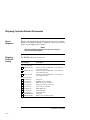
Performance
Features
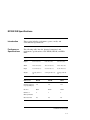
EF5XX-series disks offer powerful performance features that
are not typically available on disk storage devices in this form
factor. Table 1–1 lists some of these features:
Table 1–1 EF5XX Series Performance Features
1–6
Feature
Function
Multihost support
This allows a single ISE to be used by more than one host
at the same time. For example, two VAX4000 systems
can be booted from a single ISE.
670-bit Error
Correction Code
(ECC)
EF5XX ISEs store a large, 670-bit ECC in each block,
capable of correcting up to 320 erroneous bits.
Controllerinitiated Bad
Block Replacement
(BBR)
With controller-initiated BBR, the ISE presents the
host with a set of logically contiguous blocks, and
disk capacity does not decrease because bad blocks
are detected and automatically moved to spare blocks.
Replacement
Control Table
(RCT) Cache
DSSI ISEs cache the RCT allowing replaced blocks to
be located without the time required to access the RCT
stored on the media.
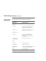
EF5XX ISE Specifications
Introduction
This section includes performance, power, media, and
environmental specifications.
Performance
Specifications
The following table lists the physical, functional, and
performance specifications of the EF51R, EF52R, and EF53
ISEs:
Physical
EF51R
EF52R
EF53
Height
8.26 cm (3.25")
8.26 cm (3.25")
8.26 cm (3.25")
Width
14.60 cm (5.75")
14.60 cm (5.75")
14.60 cm (5.75")
Depth
20.32 cm (8.00")
20.32 cm (8.00")
20.32 cm (8.00")
Weight
2.55 kg (5 lbs 10
oz)
2.32 kg (5 lbs 2 oz)
2.21 kg (4 lbs 14
oz)
Functional
EF51R
EF52R
EF53
Formatted Storage
Capacity (Mbytes)
107
205
267
Interface
DSSI
DSSI
DSSI
Number of
Memory Modules
2
1
5
Data Retention
Yes
Yes
No
Continued on next page
1–7
EF5XX ISE Specifications, Continued
Performance
EF51R
EF52R
EF53
Avg Access Time
(ms)
.25
.25
.25
Peak Transfer
Rate to DSSI Bus
(Mbytes/sec)
4.00
4.00
4.00
Start Time (total
min)
2.00
2.00
2.00
NOTE
The average access time includes commands, array
access, Error Correction Code (ECC), and buffer
delays. It does not include host software or host
adapter latency.
Continued on next page
1–8
EF5XX ISE Specifications, Continued
Current
and Power
Consumption
The following table lists the maximum current and power
consumption and the typical current and power specifications:
Maximum
Current & Power
EF51R
EF52R
EF53
Normal
0.0
0.0
2.2
Peak
0.0
0.0
3.7
Normal1
1.5
1.4
0.0
Peak2
2.3
2.2
0.1
Normal1
18.0
16.6
11.2
Peak2
27.6
26.2
18.4
5.0 V Supply
Current (amps)
12.0 V Supply
Current (amps)
Total Power
(watts)
1 "Normal maximum" indicates the maximum power and current under normal
conditions with heavy drive activity occurring.
2 "Peak maximum" indicates the maximum power and current under peak
conditions with heavy drive activity occurring. With the EF51R and EF52R,
peak power occurs during the first half hour of fast charge after full discharge.
With the EF53, peak power occurs during self-test, which happens during the
first two minutes of operation.
Continued on next page
1–9
EF5XX ISE Specifications, Continued
Typical Current
& Power
EF51R
EF52R
EF53
5.0 V Supply
Current (amps)
0.0
0.0
1.8
12.0 V Supply
Current (amps)
1.2
1.0
0.0
Total Power
(watts)
14.3
12.4
8.9
Continued on next page
1–10
EF5XX ISE Specifications, Continued
Environmental
Specifications
The following table lists environmental specifications:
Environmental
Specifications
EF51R, EF52R, EF53
Temperature
Operating
10 to 50°C (50 to 122°F), ambient, with
a gradient of 11°C (20°F) per hour (as
introduced to the drive enclosure)
Non-operating
-40 to 66°C (-40 to 151°F), ambient, with a
gradient of 20°C (36°F) per hour
Relative humidity
Operating
10 to 90% with maximum wet bulb
temperature of 28°C (82°F) and a
minimum dew point of 2°C (36°F), with
no condensation
Non-operating
(storage/shipping)
8 to 95%, with no condensation
Altitude
Operating
2,438 meters (8,000 feet)
Non-operating
4,876 meters (16,000 feet)
Noise (closed office
environment)
4.2 Bels operating (ISO 779) EF51R, EF52R
0.0 Bels operating (ISO 779) EF53
Air flow
15 ft³/min (minimum)
1–11
Shipping Contents/Related Documents
Check
Shipment
Ensure your shipment has all the items listed on the contents
listing. If any item is missing or damaged, contact your delivery
agent or your Digital representative.
NOTE
Save the packing materials until you are sure you
will not reship any items.
Shipping
Contents
Listing
The EF5XX and its accessories are:
Part Number
One of the following:
EF51R–AA, AF
EF52R–AA, AF
EF53–AA, AF
All of the following:
74–45432–01
70–27049–04
17–03571–01
17–03572–01
17–03573–01
12–28766–19
36–33183–02
36–33183–04
EK–EF5XX–UG
EK–BA44A–IN
Description
Solid state disk, 107 MB, with a 5-1/4-inch drive
and a DSSI controller
Solid state disk, 205 MB, with a 5-1/4-inch drive
and a DSSI controller
Solid state disk, 267 MB, with a 5-1/4-inch drive
and a DSSI controller
Wedges (2)
Disk Drive Bezel Assembly
DSSI flat cable (50 conductor)
Front panel cable (10 conductor)
Power cable (5 conductor)
DSSI ID plug kit
Label RF71 drive
Label RF71 drive
User guide
BA400-series installation guide
Continued on next page
1–12
Shipping Contents/Related Documents, Continued
Related
Documents
Along with your system documentation, the following
documents supplement this guide:
Title
Order Number
BA400-Series Enclosures Storage
Devices Installation Procedures
EK–BA44A–IN
DECarray Installation Guide
EK–SF2XX–IG
1–13
Chapter 2
Installation Overview
Introduction
In this Chapter
This chapter tells you how to prepare the EF5XX ISE and
install the ISE into the:
BA400-series system enclosure
SF7X storage enclosure
For more detailed information about the:
Installation into the BA400-series enclosure, refer to
BA400-Series Enclosures Storage Devices Installation
Procedures, (EK–BA44A–IN).
SF7X enclosure, refer to DECarray Installation Guide,
(EK–SF2XX–IG).
2–1
Installing into the BA400-Series Enclosure
Preparing
for the
Installation
To prepare for the installation:
CAUTION
Static electricity can damage integrated circuits.
Use the antistatic wrist strap and antistatic pad
found in the static-protective field service kit
(29-26246-00) when you work with the internal
parts of a computer system.
Handle the ISE with care. Dropping or bumping the
ISE can damage the disk surface.
1. After the system manager shuts down the operating system,
set the lock of the enclosure to the bottom position to open
both the top and bottom enclosure doors.
2. Set the enclosure power switch to off (0).
3. Always install ISEs working from right to left.
NOTE
The first or rightmost mass storage cavity in
the mass storage area is wider than the rest to
accommodate a larger device such as a tape
drive. A small filler panel (70-27414-01) is used
to fill the gap when an EF5XX ISE is installed in
this first cavity.
4. Loosen the captive Phillips screw at the top of the blank
ISE front panel assembly and remove the panel.
Before installing an EF5XX-series ISE into a BA400-series
enclosure, you must first remove the skid plate, explained in
the next section.
Continued on next page
2–2
Installing into the BA400-Series Enclosure, Continued
Removing the
Skid Plate
Remove the plastic skid plate from the right side of the ISE by
removing the four screws (Figure 2–1). Discard the skid plate.
Continued on next page
2–3
Installing into the BA400-Series Enclosure, Continued
Figure 2–1 Removing the Plastic Skid Plate (AF or AA version only)
Skid Plate
Screws
Screws
MLO-009302
Continued on next page
2–4
Installing into the BA400-Series Enclosure, Continued
Installation
Steps
To install the ISE into the BA400-series enclosure:
1. With the side that had the skid plate attached to it facing to
the right, slide the ISE along the guide rails into the mass
storage cavity (Figure 2–2A).
2. Using the upper and lower finger cutouts on the ISE
brackets, firmly push the ISE brackets until the interface
card at the rear of the ISE plugs into its backplane
connector. The guide tabs on the upper and lower brackets
should line up with the cutouts in the chassis. Tighten the
two captive screws (Figure 2–2A).
CAUTION
It is normal to have a small gap between the ISE
mounting bracket tabs and the enclosure frame.
Tighten the captive screws only until they are
securely fastened (9 inch-pounds). Do not try to
force the tabs to fit flush against the frame.
3. Plug the remote front panel cable(s) into the connector(s)
inside the ISE front panel (Figure 2–2B).
Use Velcro on the cable and on the inside of the ISE front
panel to secure the remote front panel cable.
4. Attach the ISE front panel to the enclosure by first fitting
the panel’s lower tabs into position. Fit the panel into
position and secure the panel with its single captive Phillips
screw (Figure 2–2D).
Continued on next page
2–5
Installing into the BA400-Series Enclosure, Continued
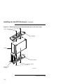
Figure 2–2 Installing the ISE in the Enclosure (RF and RZ front panels shown for
reference.)
A
Captive Screws
Remote Front
Panel Cable
Guide
Tabs
Phillips Screw
Finger Cutouts
B
C
D
Remote Front
Panel Cable
Remote Front
Panel Cable
Velcro
EF/RF/RZ 5.25-inch
RF 3.5-inch
RZ 5.25-inch
MLO-007244
Continued on next page
2–6
Installing into the BA400-Series Enclosure, Continued
For further information, refer to the BA400-Series Enclosures
Storage Devices Installation Procedures, (EK–BA44A–IN).
2–7
Installing into the SF7X Enclosure
Preparing
for the
Installation
Prepare for the installation into an SF7X enclosure as detailed
in the DECarray Installation Guide, (EK–SF2XX–IG).
CAUTION
Static electricity can damage integrated circuits.
Use the antistatic wrist strap and antistatic pad
found in the static-protective field service kit
(29-26246-00) when you work with the internal
parts of a computer system.
Handle the ISE with care. Dropping or bumping the
ISE can damage the disk surface.
Before installing into the SF7X enclosure, you must first:
Remove the ISE’s top and bottom brackets
Insert wedges on the ISE
Removing the brackets and inserting the wedges are explained
in the next sections.
Removing the
Brackets
To remove the ISE’s top and bottom brackets:
1. Place the ISE on an antistatic mat.
2. Remove the two Phillips screws at the rubber shock
bushings that secure the top bracket to the side of the
chassis (Figure 2–3). Put the screws aside.
3. Slide the interface card assembly up and lift off the top
bracket (Figure 2–3). Place the bracket aside.
4. Unplug the interface card assembly power cable (5 pin
cable) from the drive.
5. Unplug the interface card assembly 50 pin data cable from
the drive.
6. Unplug the remote front panel cable from the drive.
Continued on next page
2–8
Installing into the SF7X Enclosure, Continued
7. Remove the ISE bottom bracket by removing the two
Phillips screws at the rubber shock bushings that secure
the bracket to the chassis (Figure 2–3).
NOTE
Carefully note the orientation and routing of the
remote front panel cable.
Continued on next page
2–9
Installing into the SF7X Enclosure, Continued
Figure 2–3 Removing the Top and Bottom Brackets (AF or AA version only)
Screws
Top Bracket
Chassis
Bottom Bracket
Screws
Interface Card
Assembly
MLO-009303
Continued on next page
2–10
Installing into the SF7X Enclosure, Continued
Inserting the
Wedges
To insert the wedges:
1. Remove the two wedges from the shipment box.
2. Hold one wedge at the front end (contains the screw) and
insert the two rear prongs into the two elongated holes on
the side of the chassis (Figure 2–4). The two holes are 2-3/4
inches from the rear of the chassis.
3. Lower the front end of the wedge and insert the front
prongs into the two circular holes next to the connectors on
the front of the drive (Figure 2–4).
4. Do the same steps to insert the other wedge on the opposite
side of the chassis.
Continued on next page
2–11
Installing into the SF7X Enclosure, Continued
Figure 2–4 Inserting the Wedges on the EF5XX ISE
Continued on next page
2–12
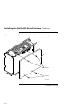
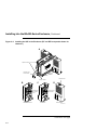
Installing into the SF7X Enclosure, Continued
Installation
Steps
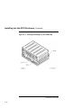
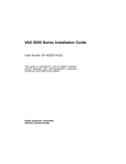
To install the ISE into the SF7X enclosure (Figure 2–5):
1. With the ISE skid plate facing the enclosure guide rails,
slide the ISE along the guide rails until the ISE is locked in
place inside the SF7X enclosure.
2. Use a Phillips head screwdriver to tighten the screws on
the wedges, so the ISE sets securely in the enclosure.
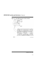
3. Take the three extension cables from the shipping box:
DSSI flat cable (50 conductor)
Front panel (Operator Control Panel (OCP)) cable (10
conductor)
Power cable (5 conductor)
4. Connect one end of each extension cable to the EF5XX ISE
and the other end of each extension cable to the cables
already attached (Figure 2–5) to the SF7X enclosure.
Continued on next page
2–13
Installing into the SF7X Enclosure, Continued
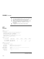
Figure 2–5 The SF7X Enclosure
NOTE TO
ILLUSTRATOR:
front panel for this
hardware is SHR_X1127_89
ISOL and reduced
17/64 (.265625)
e
SI R
DS
ID
SI
DS
ID
di
R
gi
d
ea
l
e Fa
r it t
W tec
yP r o
ta
eF
r it t
W tec
y ro
ad P
au
lt
DSSI CABLE
u lt
10-PIN
OCP CABLE
5-PIN DRIVE
POWER CABLE
SHR-X0135A-90
For more information about the SF7X enclosure, refer to the
DECarray Installation Guide, (EK–SF2XX–IG).
2–14
Chapter 3
Controls and Indicators
Introduction
In this Chapter
This chapter describes the controls and indicators associated
with ISE operation. The controls and indicators are located on
the:
Operator control panel (OCP) on the system enclosure
ISE front panel (Figure 3–1)
Operator
Control Panel
(OCP)
The operator control panel (OCP) is a set of controls on the
enclosure that overrides the drive module switches and lets
you set the DSSI node ID and write-protect mode for the ISE.
The OCP also contains a fault LED that indicates if the ISE is
malfunctioning.
Continued on next page
3–1
Introduction, Continued
The following table compares the OCPs in the and BA400-series
and SF7X enclosures.
3–2
In the ...
an OCP ...
BA400-series enclosures,
is contained on each
ISE and is mounted to
a panel in front of the
ISE (Figure 3–1).
SF7X enclosure,
contains four identical
sets of controls and
indicators.
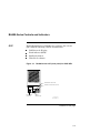
BA400-Series Controls and Indicators
OCP
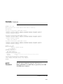
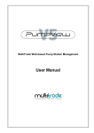
Each ISE installed in a BA400-series enclosure has a front
panel with the following controls and indicators:
DSSI bus node ID plug
Fault indicator (LED)
Run/Ready button
Write-Protect button
Figure 3–1 BA400-Series OCP (front panel) for DSSI ISEs
RUN/READY BUTTON
WRITE-PROTECT BUTTON
BUS NODE
ID PLUG
FAULT
INDICATOR
MLO-004044
SHR-X0058-90
Continued on next page
3–3
BA400-Series Controls and Indicators, Continued
Control and
Indicator
Functions
The following table describes the functions of the controls and
indicators on the BA400-series DSSI operator control panel:
Control
Status
Function
Fault LED
Lit
Indicates an error condition within the ISE.
Not lit
Indicates an error-free condition within the
ISE.
Quick flash
(10 Hz)
OCP failure, or drive select plug is missing.
In (lit)
The ISE is on line. When the ISE is available
for use, the green LED is lit. When the ISE is
being used, the green LED flickers.
Out (not lit)
The ISE is off line and cannot be accessed. The
green LED cannot be lit when the Run/Ready
button is out.
Slow flash (1
Hz)
Data retention system is initializing, saving, or
restoring data.
In (lit)
The ISE is write-protected. System software
cannot write to the ISE.
Out (not lit)
The ISE is not write-protected. This is the
normal position for software operation. System
software is free to read or write to the ISE.
Run/Ready
Button
WriteProtect
Button
3–4
Changing the DSSI Node ID Plugs (BA400-Series OCPs)
Spare Plugs
Spare DSSI node ID plugs are supplied with the EF5XX. Use
these spare plugs to reconfigure your DSSI system because of
adding or removing ISEs or creating a multihost configuration.
Removal
The DSSI node ID plugs have prongs on the back that indicate
the bus node number (and by default, the unit number) of the
ISE. To remove a DSSI node ID plug, grasp it firmly and pull it
straight out.
Insertion
To insert a new plug, align the two center prongs with the two
center slots and press the plug into the slots.
Renumbering
ISEs
Use the following rules to renumber your ISEs:
For each DSSI bus, do not use duplicate DSSI node IDs.
By convention, ISEs are numbered in increasing order from
right to left and top to bottom.
Use a blank DSSI node ID plug where no ISE is present.
NOTE
If you change the bus node ID plugs while the
system is operating, you must turn off the system
and then turn it back on for the new plug positions
to take effect.
3–5
SF7X Controls and Indicators
OCP
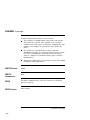
Each ISE in the SF7X storage enclosure is represented by an
icon on the door located on the OCP. Each set of controls and
indicators is dedicated to one of the four storage compartments
in the enclosure (Figure 3–2).
Figure 3–2 SF7X Controls and Indicators
digi tal
Write
Ready Protect Fault
DSSI
ID
1
DSSI
ID
Write
Ready Protect Fault
2
SHR_X1128_89
Continued on next page
3–6
SF7X Controls and Indicators, Continued
Control and
Indicator
Functions
The following table describes the functions of the controls and
indicators on the front of the SF7X enclosure.
Control/
Indicator
Color
Function
Ready
Green
Illuminates when ISE is on
line and read/write ready.
Fault
Red
Illuminates when fault is
detected.
DSSI Node ID
Green
Displays ISE DSSI Node ID.
Write Protect
Yellow
Commands write protect
mode. Shows write protect
enabled.
Terminator Power
Green
On while when Terminator
Power is being supplied.
Split Bus
Green
On when enclosure is in
Split Bus mode.
DSSI Node ID Select
N/A
3 bits, selects DSSI node ID
number.
MSCP Enable/Disable
N/A
1 bit, enables or disables the
ISE MSCP server.
DC power switches (4)
Green
Applies DC power to ISE.
Shows power status.
3–7
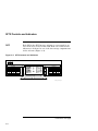
EF5XX ISE Controls and Indicators
Description
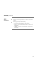
Two LEDs and a DIP switchpack containing three switches are
mounted on the edge of the drive module. The switches provide
a means of setting the DSSI node ID if an OCP is not connected
to the drive, or if the OCP fails. The two LEDs indicate drive
status:
READY LED
FAULT LED
Figure 3–3 shows the location of the switches and LEDs on the
drive module.
Continued on next page
3–8
EF5XX ISE Controls and Indicators, Continued
Figure 3–3 Drive Module Switch and LED Locations
Continued on next page
3–9
EF5XX ISE Controls and Indicators, Continued
Assigning the
DSSI Node ID
To assign the DSSI node ID, set the three switches to the binary
equivalent of the selected ID number, as shown in the following
table. These switches are ignored when an operator control
panel is connected to the ISE.
DSSI Node ID
Switch Positions1
Address
1
2
3
Up
Up
Up
Up
Down
Down
Down
Down
Up
Up
Down
Down
Up
Up
Down
Down
Up
Down
Up
Down
Up
Down
Up
Down
0
1
2
3
4
5
6
72
1 Up
is toward the top cover of the EF5XX, down is toward the module.
2 DSSI
address 7 is normally assigned to a host adapter.
Continued on next page
3–10
EF5XX ISE Controls and Indicators, Continued
Drive Module
LEDs
The two LEDs mounted on the drive module monitor ISE status
during operation. The following table describes the state of
these two LEDs during the various phases of ISE operation.
When . . .
The green
LED is . . .
And the yellow LED
is . . .
The ISE is first powered up
On
On
POST has run successfully
Off
Off
The ISE is ready to accept a
command
On
Off
Drive activity
Flickering
Off
A read/write or serious physical
error is detected
Off
On
The ISE is saving or restoring
data to the data retention
system
Blinking once
per second
Off
3–11
Chapter 4
Local Programs
Introduction
In this Chapter
This chapter includes:
How to access local programs through the VMS system, the
console, and the MicroVAX Diagnostic Monitor (MDM)
Descriptions of accessible local programs
Overview
Local programs are diagnostics and utilities that are internal to
the ISE. You can access them in one of three ways, depending
on which system you are using.
Continued on next page
4–1
Introduction, Continued
The following table refers to each section with instructions on
how to access local programs:
To access local programs ...
Refer to ...
Through VMS, using the SET HOST
command,
Using VMS
From the console, using the SET HOST
command,
Using Console
Commands
Through MDM, using the Device Resident
Programs menu,
Using MDM
Once you establish a connection, the local program controls the
operations that are performed. The following is a list of local
programs and the sections in which they are located:
Continued on next page
4–2
Introduction, Continued
Programs1
Section
DIRECT
DIRECT Program Description
DRVEXR
DRVEXR Program Description
DRVTST
DRVTST Program Description
HISTRY
HISTRY Program Description
DRINIT
DRINIT Program Description
BATTST
BATTST Utility Description
MEMTST
MEMTST Utility Description
PARAMS
PARAMS Utility Description
1 For users familiar with the RF-series ISEs, notice that the DKUTIL, ERASE,
and VERIFY local programs are not available in the EF5XX-series ISEs.
The DRINIT local program in the EF5XX provides a function similar to the
ERASE utility. The STATUS BB command in PARAMS provides the bad block
information available in DKUTIL and VERIFY.
When the program ends, control returns to the system. To abort
the program and return control to the system, press Ctrl/C or
Ctrl/Y .
4–3
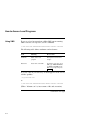
How to Access Local Programs
Using VMS
To access a local program from a MicroVAX system running
VMS version 5.3-2 or greater, use the command:
$ SET HOST/DUP/SERVER=MSCP$DUP/TASK=taskname nodename
The following table defines taskname and nodename:
Term
Meaning
How to find
Taskname
Name of the local
program
Descriptions found in this
chapter
Nodename
Node name of the ISE
To find the node name of an
ISE, type SHOW DEVICES
or SHOW CLUSTER at the
DCL ( $ ) prompt and press
Return
To create a file in your directory of what appears on the screen,
add the qualifier:
/log=filename.ext
to:
$ SET HOST/DUP/SERVER=MSCP$DUP/TASK=taskname nodename
(Where "filename.ext" is, insert name of file and extension.)
Continued on next page
4–4
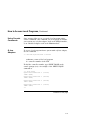
How to Access Local Programs, Continued
Using Console
Commands
Some systems allow you to access the local programs using
console commands. The command you use depends on whether
your system uses a Q–bus adapter such as the KFQSA module,
or an embedded adapter such as the KA640 module.
Q–bus
Adapters
To access a local program from a system with a Q–bus adapter,
use the command:
>>> SET HOST/UQSSP/DUP/DISK # taskname
taskname = name of the local program
# = controller number of the ISE
To find the controller number, type SHOW UQSSP at the
console prompt (>>>). An example of the SHOW UQSSP
command is:
>>> show uqssp
UQSSP Disk Controller 0 (772150)
-DUA0 (RF31)
UQSSP Disk Controller 1 (760334)
-DUB1 (RF31)
UQSSP Disk Controller 2 (760340)
-DUC2 (RF31)
UQSSP Tape Controller 0 (774500)
-MUA0 (TK70)
>>>
Continued on next page
4–5
How to Access Local Programs, Continued
Q–bus
Adapters
(continued)
To access a local program from a system with an embedded
adapter, use the command:
>>> SET HOST/DUP/DSSI/BUS:n #
n = bus number where the ISE is located
# = DSSI node number of the ISE
The system then prompts you for the name of the local program
you want to run.
To find the DSSI node number and node name, type SHOW
DSSI at the >>> prompt. To see a list of the devices on
the Q–bus, type SHOW QBUS or SHOW UQSSP at the >>>
prompt.
To abort the program and return control to the system, press
Ctrl/C or Ctrl/Y .
Continued on next page
4–6
How to Access Local Programs, Continued
Using MDM
If neither VMS nor console commands are available on your
system, you can run local programs using MDM. Use the
following procedure:
1. Boot MDM.
2. Enter the date and time.
3. Select the menus in the following order:
Service menu
Device menu
KFQSAA-KFQSA subsystem menu
Device Utilities menu
Device Resident Programs menu
When you select the Device Resident Programs menu, the
following displays:
RUNNING A UTILITY SERVICE TEST
To stop the test at any time and return to the previous
menu, press CTRL/C .
Continued on next page
4–7
How to Access Local Programs, Continued
Using MDM
(continued)
4. Enter the name of the local program you want to run and
press Return . For information about the available local
programs, refer to the program descriptions on the following
pages.
5. To exit MDM, press the Break key.
4–8
Descriptions of Local Programs
Overview
)DIRECT
Program
Description
The rest of this chapter describes local programs you can access.
The DIRECT program provides a directory of local programs
resident in the ISE.
4–9
DRVEXR
)DRVEXR
Program
Description
The DRVEXR program is a diagnostic program that applies
several types of stress to the ISE.
Access DRVEXR the same way you would the other local
programs. Once a connection is established, the system
prompts you to answer a series of questions. Your responses
determine the mode and test duration.
Stopping
DRVEXR
To stop DRVEXR in progress, press Ctrl/C , Ctrl/Y , or Ctrl/Z .
When DRVEXR stops, a short report is printed.
Dialogue
To run DRVEXR, first respond to the following dialogue
messages:
Message
Explanation
Copyright © 1989 Digital Equipment
Corporation
No response is expected.
Write/read anywhere on the medium?
[1=Yes/(0=No)]
Do you want to write to the user data
area?
User data will be corrupted. Proceed?
[1=Yes/(0=No)]
(This question is omitted if you typed
0 to answer the previous question.)
Do you really want to overwrite
existing data on the user data area?
Continued on next page
4–10
DRVEXR, Continued
Dialogue
(continued)
Message
Explanation
Test time in minutes?
[(10)-100]
Your response determines the length
of the test, in minutes.
Number of sectors to transfer at a
time? [0 - 50]
This question is included for
compatibility with DRVEXR in RFseries ISEs. The response can be any
valid entry, 0 through 50. The entry
is checked for validity, but otherwise
ignored.
Compare after each transfer? [1=Yes
/(0=No)]
Your response determines whether the
processor ‘‘manually’’ compares the
results of the read with the expected
data (if writing is enabled) or the
hardware does the compares after
each read.
Test the DBN area?
[2=DBN only/(1=DBN and LBN)
/0=LBN only]:
Your response determines how to
include the DBN area in the test. If
you enter 2, the test always includes
writes, even if you answered the first
question with 0.
Continued on next page
4–11
DRVEXR, Continued
DRVEXR
Modes
You can run the DRVEXR program in one of the following
modes depending on your responses to the dialogue questions:
Mode
Function
Read/Write
Writes and reads as many blocks as possible in the given
amount of time.
Data Integrity
Similar to Read/Write mode, but with a ‘‘manual’’ check
of data buffers done by the ISE processor.
Max Stress
Reads the inner DBNs and outer DBNs alternately.
Continued on next page
4–12
DRVEXR, Continued
Mode/Dialogue
Relationship
The following table shows the relationship between the four test
modes and the responses to the six questions in the dialogue:
Modes
Example
Response to Question
1
2
3
4
5
6
Read/Write
1
1
Any
Any
0
Any
Data Integrity
1
1
Any
Any
1
Any
Max Stress
0
N/A
Any
0
N/A
2
The following is an example of what is displayed when you run
DRVEXR.
Copyright (C) 1990, 1991, 1992 Digital Equipment Corporation
Write/read anywhere on medium? [1=Yes/(0=No)] 1
User data will be corrupted. Proceed? [1=Yes/(0=No)] 1
Test time in minutes? [(10)-100]
Number of sectors to transfer at a time? [0 - Device Size] 1
Compare after each transfer? [1=Yes/(0=No)]: 1
Test the DBN area? [2=DBN only/(1=DBN and LBN)/0=LBN only]: 1
10 minutes to complete.
249080 operations completed.
124508 LBN blocks (512 bytes) read.
124508 LBN blocks (512 bytes) written.
32 DBN blocks (512 bytes) read.
32 DBN blocks (512 bytes) written.
0 uncorrectable ECC errors.
0 bytes in error (soft).
Complete.
4–13
DRVTST
DRVTST
Program
Description
The DRVTST program provides a comprehensive test of the ISE
hardware. Errors detected by this program can be isolated to
the FRU level.
Dialogue
The following table describes the DRVTST dialogue:
Message
Explanation
Copyright © 1989 Digital Equipment
Corporation
No response is expected.
Write/read anywhere on the medium?
[1=Yes/(0=No)]
Do you want to write to the user data
area? If you type 0, this is a read-only
test. DRVTST does, however, write to
a diagnostic area on the disk.
User data will be corrupted. Proceed?
[1=Yes/(0=No)]
Do you really want to overwrite
existing data on the user data area?
If you type 0, this is a read-only test.
5 minutes to complete.
No response is expected.
Test passed.
The test was successful. Choose
another local program or return
control to the system.
Continued on next page
4–14
DRVTST, Continued
Error
Messages
The following table describes DRVTST error messages.
Message
Description
Unit is currently in use.
This can mean that the ISE unit is
inoperative, in use by a host, or is currently
running another local program.
Operation aborted by user.
This message appears if the user stops the
program while it is in progress.
xxxx - Unit diagnostics failed.
This is a fatal error message where xxxx is
the MSCP error code. Call Digital Services.
xxxx - Unit read/write test
failed.
This is also a fatal error message where
xxxx is the MSCP error code. Call Digital
Services.
Continued on next page
4–15
DRVTST, Continued
DRVTST
Examples
The following is an example of what is displayed when DRVTST
runs successfully:
Copyright (C) 1990, 1991, 1992 Digital Equipment Corporation
Write/read anywhere on medium? [1=Yes/(0=No)] 1
User data will be corrupted. Proceed? [1=Yes/(0=No)] 1
5 minutes to complete.
Test passed.
The following is an example of what is displayed when DRVTST
has failed:
Copyright © 1989 Digital Equipment Corporation
Write/read anywhere on medium? [1=Yes/(0=No)]
0106 - Unit read/write test failed.
4–16
HISTRY
HISTRY
Program
Description
The HISTRY program displays ISE information that is used by
programs running in the host (such as MDM).
The information is displayed in the following order:
copyright notice
product name
serial number
node name
allocation class
firmware revision level
hardware revision level
power-on hours
power cycles
last bug check codes (up to 11)
Example
The following is an example of what is displayed when you run
the HISTRY program:
Copyright (C) 1990, 1991, 1992
EF53
GA23040879
E1ZDCI
1
RFX T043
EF53 PCB-1/ECO-00
236
1
Complete.
Digital Equipment Corporation
4–17
DRINIT
DRINIT
Program
Description
The DRINIT program initializes the firmware data structures
and on-disk structure of the internal data retention disk. This
prepares the EF5XR ISE for saving data in case of a power
failure.
CAUTION
You should not normally need to run DRINIT. Use
the DRINIT program with caution, since running it
erases the EF5XX.
Copyright (C) 1990 Digital Equipment Corporation
User data will be corrupted. Proceed? [1=Yes/(0=No)] 1
Test passed.
4–18
BATTST
BATTST Utility
Description
BATTST is a utility that allows testing the batteries in an
EF51R and EF52R. It also allows for conditioning the batteries
to avoid or correct the voltage depression effect that sometimes
occurs in nickel-cadmium batteries after a series of incomplete
discharges.
BATTST operates by continuing to exercise the memory and
data retention disk under battery power after external DC
power is removed. The time that the batteries lasted is stored
in the PARAMS parameter BAT_TEST.
Accessing
BATTST
Access the BATTST program the same way you would the other
local programs. Once a connection is established, the system
prompts you to answer a series of questions.
Continued on next page
4–19
BATTST, Continued
Stopping
BATTST
To stop a BATTST in progress, re-execute the BATTST local
program. You will be given an opportunity to abort the test.
Aborting BATTST requires the EF5XX to reset itself.
Digital recommends running the BATTST utility at least once
per year, or whenever a "Battery Maintenance Error" is logged
to the error log. This error is logged when EF5XX charging
and battery test firmware detect potential problems with the
charging or discharging of the batteries.
The result of the BATTST utility is checked by examining the
BAT_TEST parameter with the PARAMS utility. BAT_TEST
gives the time, in minutes and seconds, that the batteries ran
under the BATTST utility. A time:
Greater than 30 minutes indicates a good battery
Less than 30 minutes indicates that you should call Digital
Services to replace the battery
Continued on next page
4–20
BATTST, Continued
Dialogue
The following table explains the BATTST dialogue.
Message
Explanation
Copyright © 1990,1991,1992 Digital
Equipment Corporation
No response is expected.
Test requires the unit power to be
removed. Proceed? [1=Yes/(0=No)]
Do you want to remove power from
the EF5XX? This may affect other
drives in the cabinet or may require a
system shutdown.
Remove external power, Variable
BAT_TEST will contain the time
Remove power from the EF5XX under
test. Depending on the configuration,
this may require a system shutdown.
After the test is completed, the
results are available in the parameter
BAT_TEST.
Test passed.
This message indicates that the
BATTST operation has started. The
program stops automatically when the
batteries are exhausted.
Continued on next page
4–21
BATTST, Continued
Example
The following is an example of the BATTST utility:
Copyright © 1990, 1991, 1992 Digital Equipment Corporation
Test requires the unit power to be removed.
Proceed? [1=Yes/(0=No)] 1
Remove external power, Variable BAT_TEST will contain the time
Test passed.
After removing the power and allowing the batteries to drain,
the following example shows how to get the test results. In this
case, the batteries lasted for 40 minutes and 12 seconds.
Copyright © 1990, 1991, 1992 Digital Equipment Corporation
PARAMS>SHOW
Parameter
--------BAT_TEST
PARAMS>EXIT
Exiting...
4–22
BAT_TEST
Current
-------00:40:12
Default
-------00:00:00
Type
----String
Radix
-----Ascii
MEMTST
MEMTST
Utility
Description
MEMTST is a utility that allows testing of the memory modules
in EF5XX drives. Various patterns are written and read to the
memory arrays to detect problems with the memory devices,
address and data buffers, memory control, and ECC logic.
Accessing
MEMTST
Access the MEMTST program the same way you would the
other local programs. Once a connection is established, the
system prompts you to answer a series of questions.
Continued on next page
4–23
MEMTST, Continued
Dialogue
The following table explains the MEMTST dialogue.
Message
Explanation
Copyright © 1990,1991,1992 Digital
Equipment Corporation
No response is expected.
User data will be corrupted. Proceed?
[1=Yes/(0=No)]
Do you want to overwrite the data in
the memory arrays?
Test time in minutes? [0 (= 1 pass)
<-> 200]
Enter the time to run the test. Enter
0 to run the test once on memory
module.
Testing slot n:
Memory module n is currently being
tested.
Array OK - has 2 bad blocks
The memory module has passed the
test with the indicated number of bad
blocks.
Test completed.
The test has finished without errors.
Continued on next page
4–24
MEMTST, Continued
Example
The following is an example of a successful run of the MEMTST
utility. In this case, each memory module was tested twice and
passed.
DUP Array Bad Block Test
Copyright © 1990, 1991, 1992
Digital Equipment Corporation
User data will be corrupted.
Proceed? [1=Yes/(0=No)] 1
Test time in minutes? [0 (= 1 pass) <-> 200] 16
Testing slot 0:
Array OK - has 2 bad
Testing slot 1:
Array OK - has 0 bad
Testing slot 2:
No array installed
Testing slot 3:
No array installed
Testing slot 4:
No array installed
Testing slot 0:
Array OK - has 2 bad
Testing slot 1:
Array OK - has 0 bad
Testing slot 2:
No array installed
Testing slot 3:
No array installed
Testing slot 4:
No array installed
Testing slot 0:
blocks
blocks
blocks
blocks
Test completed.
Continued on next page
4–25
MEMTST, Continued
To test each memory module just once, use a test time of 0 as
shown in the following example. MEMTST will calculate a test
time based on the number of memory arrays installed.
DUP Array Bad Block Test
Copyright © 1990, 1991, 1992
Digital Equipment Corporation
User data will be corrupted.
Proceed? [1=Yes/(0=No)] 1
Test time in minutes? [0 (= 1 pass) <-> 200] 0
1 pass (=
10 minutes) selected
Testing slot 0:
Array OK - has 2 bad blocks
Testing slot 1:
Array OK - has 0 bad blocks
Testing slot 2:
No array installed
Testing slot 3:
No array installed
Testing slot 4:
No array installed
Testing slot 0:
Test completed.
The following is an example of MEMTST output when a
memory module is found bad.
DUP Array Bad Block Test
Copyright (C) 1990, 1991, 1992
User data will be corrupted.
Digital Equipment Corporation
Proceed? [1=Yes/(0=No)] 1
Test time in minutes? [0 (= 1 pass) <-> 200] 10
Testing
Array
Testing
Array
4–26
slot 0:
OK - has 2 bad blocks
slot 1:
fails - has more than 20 bad blocks
PARAMS
PARAMS
Utility
Description
The PARAMS utility allows you to examine and change internal
ISE parameters such as node name, allocation class, and MSCP
unit number. You can also use PARAMS to display the state of
the ISE and performance statistics maintained by the ISE.
The PARAMS program is an interactive, customer accessible
DUP local program that functions as both a parameter editor
(similar to the VMS SYSGEN utility) and a utility to display
status, history, and counters. PARAMS also performs well as a
manufacturing tool for gauging the goodness of the drive.
PARAMS polls for control characters (note that the DUP server
strips control characters of interest out of the input stream and
sets control flags). PARAMS processes control characters as
follows:
Character
Function
CTRL/Y
Terminates the program
CTRL/C
Terminates the program
CTRL/Z
Terminates the program
CTRL/R
Ignored
CTRL/W
Ignored
CTRL/G
Emulates VMS CTRL/T behavior
Continued on next page
4–27
PARAMS, Continued
The following is an example response given to CTRL/G:
PARAMS> ^G
E1QSAA::MSCP$DUP
26-APR-1990 15:01:51 PARAMS
CPU=00:00:01.09 PI=17
PARAMS>
Accessing
PARAMS
PARAMS
Process
The PARAMS utility is invoked on demand from the user.
Once a connection is established, all interaction occurs through
the use of commands and responses. PARAMS has its own
command line interpreter.
PARAMS prompts you for a command at the PARAMS>
prompt.
Once you enter a command, PARAMS executes it and then
prompts you for another command.
Continued on next page
4–28
PARAMS, Continued
PARAMS
Commands
Available PARAMS commands are:
Name
Function
ENABLE
MSCP
Enables MSCP server
EXIT
Terminates PARAMS
HELP
Prints a brief list of commands and their syntax
LOCATE
Causes a soft fault in the ISE to help locate it
SET
Sets a parameter to a value
SHOW
Displays a parameter or a class of parameters
STATUS
Displays information about the drive’s history
WRITE
Updates the NVR from the cached copy
ZERO
Clears a block of counters or all known blocks of
counters
The following sections describe these commands.
ENABLE
MSCP
The ENABLE MSCP command, used with certain types of
hosts/configurations, enable the MSCP server.
Continued on next page
4–29
PARAMS, Continued
ENABLE
MSCP Syntax
ENABLE MSCP
ENABLE
MSCP
Parameters
EXIT
None
Use the EXIT command to terminate the PARAMS utility. The
message
Exiting...
displays on the terminal.
EXIT Syntax
EXIT
EXIT
Parameters
None
HELP
HELP displays a brief list of the available commands and their
syntax.
Command
Syntax
HELP
HELP
Parameters
None
Continued on next page
4–30
PARAMS, Continued
HELP
Example
PARAMS> help
ENABLE MSCP
EXIT
HELP
LOCATE
SET {parameter | .}
SHOW {parameter | .
/ALL
/CONST
/DUP
/SCS
/MSCP
/BSS
STATUS [type]
CONFIG
LOGS
THREADS MEMORY
MSCP
PATHS
HOURLY
VCLOGS
WRITE
ZERO counter
ALL
HOURLY
MSCP
PARAMS>
value
| /class}
DUMP
DATALINK
BB
LOCATE
The LOCATE command causes a soft fault in the ISE (it has no
effect on its current operation or state) to help find it. The fault
indicator on the drive module (red LED), the OCP (red LED), or
on the canister (magnetic disk with small green stripe) turn on
and stay on until you press Return at the PARAMS> prompt.
LOCATE
Syntax
LOCATE
parameter-name value
Continued on next page
4–31
PARAMS, Continued
LOCATE
Example
The following appears on the screen when this command is
used:
PARAMS> locate
Drive has been soft faulted to help locate it
Press RETURN to continue:
PARAMS>
SET
Use the SET command to change the value of a given parameter
in the cached copy of the NVR image that is maintained
by PARAMS. The type and radix of the new value for the
parameter is determined by the type and radix of the parameter
itself ONLY and not by radix specifiers or quotes in your input.
ASCII parameters are left justified and blanks are padded into
their field width.
SET Syntax
SET
SET
Parameters
parameter-name value
parameter-name is the name of the parameter you want
to change. If abbreviated, the first matching parameter
name is used without regard to uniqueness. In addition,
the character "." may be used to reference the previously
referenced parameter. If there is no previously referenced
parameter, an error message is displayed.
value is the value assigned to the parameter. The radix
and type is specified by the parameter and not by radix
specifiers or quotes. For example, the command SET NODE
SUSAN sets parameter NODENAME equal to SUSAN.
Continued on next page
4–32
PARAMS, Continued
SHOW
Command
Examples
NOTE
Since it is important to view the current value of a
parameter before changing it, examples of the SHOW
command are included.
PARAMS> show add_cr
Parameter
--------ADD_CR
Current
-------0
Default Type
Radix
-------- ------- -----0
Boolean
0/1
PARAMS> set . 1
PARAMS> show .
Parameter
--------ADD_CR
Current
-------1
Default
-------0
Type
Radix
-------- ----Boolean
0/1
Default
-------0
Type
Radix
-------- ----Boolean
0/1
PARAMS> set add_cr 0
PARAMS> show .
Parameter
--------ADD_CR
Current
-------0
PARAMS>
SHOW
The SHOW command displays the settings of a parameter or
a class of parameters. The full name of the parameter (8
characters or less), the current value, the default value, radix
and type, and any flag associated with each parameter is
displayed.
SHOW Syntax
SHOW
param-or-class
Continued on next page
4–33
PARAMS, Continued
SHOW
Parameters
SHOW /Class
Examples
param-or-class is either the parameter name, possibly
abbreviated, or a class name. If you use an abbreviation,
the first matching parameter displays regardless of
uniqueness. The parameter name may also be the special
character "." which displays the most recently-shown
parameter. If there is no previously-shown parameter,
an error message is displayed. If you use a class name, be
sure to prefix it with a slash ("/"). Classes available are:
ALL, CONST, SCS, MSCP, DUP, and BSS.
PARAMS> show /dup
Parameter
--------SDI_TMO
ABT_TMO
ELP_TMO
DUPEXT
ADD_CR
ADD_LF
Current
--------20
20
20
RFX
0
0
Default
--------20
20
20
RFX
0
0
Type
Radix
---------Byte
Dec
RO
Byte
Dec
RO
Byte
Dec
RO
String
Ascii RO
Boolean
0/1
Boolean
0/1
PARAMS> show add_cr
Parameter
--------ADD_CR
Current
--------0
Default
--------0
Type
Radix
-------- ----Boolean
0/1
Default
--------0
Type
Radix
-------- ----Boolean
0/1
PARAMS> show .
Parameter
--------ADD_CR
Current
--------0
PARAMS>
Continued on next page
4–34
PARAMS, Continued
STATUS
STATUS displays miscellaneous information such as module
configuration, history, current counters, and so forth, depending
on the type specified.
STATUS
Syntax
STATUS
STATUS
Parameters
type
The type is the optional ASCII string that denotes the
type of data desired. You can also abbreviate type; an
abbreviation selects all types with matching names. If
omitted, all available data are displayed. The following
types are available:
CONFIG displays the module name, node name, power
on hours, power cycles, and other such configuration
information. Any unit failures as well as NVR failures
are displayed if applicable.
BB displays the bad block log for the device. A list of
physical blocks that have been replaced is given.
LOGS displays the last eleven (11) machine and bug
checks on the module. Included in each dump are the
M68000 registers (D0-D7, A0-A7), the time and date of
the failure (if not available, 17 November 1858 is used),
and a few hardware registers.
DATALINK
displays the data link counters.
PATHS displays available path information (open VCs)
from the point of view of the controller. Included are
the remote node names, DSSI IDs, software type and
version, and counters for messages/datagrams sent
/received.
SYSTEM
displays system statistics and counters.
Continued on next page
4–35
PARAMS, Continued
MSCP displays MSCP statistics such as the number and
type of I/O commands and various histograms.
THREADS displays the known programs in the system,
the amount of CPU time consumed, and other
information.
VC
displays the last 8 virtual circuit closures.
STAT
Examples
PARAMS> stat conf
Configuration:
Node EQSAA is an EF51R controller using Apache V1.1
Software EFX V100 built on 11-MAR-1990 22:21:45
Electronics module name is EN00500250
Last known unit failure code 300D(X)
In 485 power-on hours, power has cycled 681 times
System up time is
3 22:50:02.68
System time is 23-MAR-1990 15:00:17
PARAMS> stat paths
ID
-1
0
7
Path Block
-----------PB FF846D66
PB FF846E9A
PB FF847236
Remote Node
DGS_S
DGS_R
MSGS_S
MSGS_R
--------------- ---------- ---------- ---------- ---------Internal Path
0
0
0
0
KFQS A RFX T102
0
0
0
0
KF0Y7B KFX V1.7
0
0
8393
8391
PARAMS> stat datalink
Datalink Counters:
Interval: 341421 seconds
Pkts Rcv’d:
53952:***************************
Pkts Xmt’d:
53954:***************************
Naks Rcv’d:
45717:**********************
Naks Xmt’d:
0:
Resets Rcv’d:
99662:**************************************************
Resets Xmt’d:
3040:*
No response:
42677:*********************
Duplicates:
0:
Unrecogs:
0:
Continued on next page
4–36
PARAMS, Continued
PARAMS> stat logs
NOTE: bugcheck code is last word on first line of each log.
Log History:
Log #175-27-50-01/0000 17-NOV-1858 0:00:00
FFFFFFFF 0000FFFF FFFFFFFF FFFE2801 FFFFFFFF EFFF2801 FFF7FFFB 0000A056
FFDFC029 FFDFC74B FFFFB74C BFFEFFFF FFFF80BA FBFFFFFF FFFFBFFF FFFF807C
00000000 00000000 00000000
Log #176-27-50-01/0000 17-NOV-1858 0:00:00
FFFF1441 0000004D FFFFFFFF FFFE2801 FFFFFFFF EFFF2801 FFF7FFFB 0000A050
FFDF80BE FFDFC0EB FFFFB750 BFFEFFFF FFFF80BA FBFFFFFF FFFFBFFF FFFF807C
00000000 00000000 000006EC
...Eight logs omitted...
Log #174-27-50-01/0000 17-NOV-1858 0:00:00
FFFF1441 0000004D FFFFFFFF FFFE2801 FFFFFFFF EFFF2801 FFF7FFFB 0000A050
FFDF80BE FFDFC6AF FFFFB750 BFFEFFFF FFFF80BA FBFFFFFF FFFFBFFF FFFF807C
00000000 00000000 000006EC
PARAMS> stat mscp
MSCP statistics:
Interval: 341481 seconds
I/O Commands: 0
Primary revectors: 0
Tertiary revectors: 0
Max Queue Depth: 0
Queue Depth Histogram:
Commands Processed Histogram:
GetUnit:
5691:********************************************
SetCon:
2:*
Blocks Accessed Histogram (cylinder ranges):
Read Lengths Histogram (block count ranges):
Write Lengths Histogram (block count ranges):
PARAMS>
WRITE
Command
Use the WRITE command to copy the cached copy of
NVR_G_IMAGE back to NVR. This is equivalent to the VMS
SYSGEN WRITE command.
Continued on next page
4–37
PARAMS, Continued
A
WRITE
command may fail for several reasons:
If a parameter is modified that requires the unit and the
unit cannot be acquired. (For example, it is not in the
available state with respect to all hosts. Changing the unit
number is an example of a parameter that requires the
unit.)
If a parameter is modified that requires controller
initialization and the user replies negatively to the request
for reboot. (Changing the nodename or the allocation
class are examples of parameters that require controller
initialization.)
Initial drive calibrations are in progress on the unit. (WRITE
is inhibited during this time.)
WRITE Syntax
WRITE
WRITE
Parameters
None
ZERO
The ZERO command clears a block of counters or all known
blocks of counters.
ZERO Syntax
ZERO
counter
Continued on next page
4–38
PARAMS, Continued
ZERO
Parameters
Counter is a block of performance counters or all known
counters.
Counter types include the following:
*
All - Clears all performance counter blocks.
*
MSCP - Clears the MSCP performance counters and
histograms.
*
SEEKS - Clears the seek performance counters and
histograms.
4–39
Chapter 5
Data Retention System
Introduction
In This
Chapter
The EF51R and EF52R ISEs contain advanced hardware and
firmware that protect the data in the memory arrays from loss
in case of power or other system failure.
This chapter discusses the following features of the integrated
data retention system:
Continuously saving data
Restoring data on line
Battery testing and monitoring
Fast charge circuit
Automatic write protect
Comprehensive battery test
5–1
EF5XX Data Retention Description
Continuously
Saving Data
Unlike Digital’s earlier ESE20 and ESE50 solid state disks, the
EF5XX ISE continuously moves modified data to the internal
winchester disk drive. This minimizes the amount of data
that must be saved under battery power and ensures that the
data retention disk is still functional. Saving of data is a low
priority, background task that minimizes the effect of saving
data on performance.
Upon a power failure, the EF5XX instantly switches over to
battery power. Within one minute, firmware detects external
power has failed. Firmware then write-protects the EF5XX
ISE, preventing further data changes. Saving data to the
internal winchester (magnetic) disk drive continues under
battery power until all contents of the memory arrays are safely
on the winchester disk.
The EF5XX ISE then shuts itself off to conserve battery power.
Although continuously saving data dramatically decreases the
length of time to completely save final data, the fully charged
battery has sufficient power to completely save the contents of
the EF5XX to the winchester disk. While saving the data under
battery power, the yellow Write-Protect LED will be on and the
green Run/Ready LED will blink once per second.
Restoring
Data
When power is restored, the EF5XX undergoes approximately
two minutes of power-on self-test (POST), which verifies the
integrity of the electronics and firmware.
After POST, the EF5XX is available for mounting and begins
restoring data to the memory arrays. While restoring data in
the offline state, the green Run/Ready LED blinks once per
second.
Continued on next page
5–2
EF5XX Data Retention Description, Continued
After mounting, users’ requests from the host receive top
priority and are satisfied before restore requests. If a user
requests data that has not been restored yet, the EF5XX
fetches the data from the internal magnetic disk and returns
the data to the user.
Battery
Testing and
Monitoring
The battery subsystem (BSS) firmware logs a "Battery
Maintenance Error" under certain conditions. Table 5–1 lists
the type of error and why it occurs:
Table 5–1 Battery Maintenance Errors
Error
Reason
Battery failed periodic test.
The batteries undergo
a periodic trickle test
to check for shorted
cells.
Continued on next page
5–3
EF5XX Data Retention Description, Continued
Table 5–1 (Continued) Battery Maintenance Errors
Error
Reason
Battery age.
The batteries have
had more than 3 years
of power-on time and
need to be replaced.
The number of poweron days until the
battery needs to be
replaced is available
in the parameter
BSS_REPL. A value
of 0 indicates the age
is the cause of the
maintenance error.
Battery charging out-of-specification.
Battery charging
time was not within
specification.
Battery deep discharge.
If the parameter BSS_
SHUT is 0 and the
BSS_DISC is 1, the
batteries were deep
discharged on the
last power failure and
should be replaced.
Continued on next page
5–4
EF5XX Data Retention Description, Continued
Using
PARAMS
Use the PARAMS local program (Chapter 4) to check the cause
of the battery maintenance error. You can use the PARAMS
command SHOW /BSS to show all BSS parameters. Except in
the case of deep discharge, use the battery test utility BATTST
to verify battery health when a "Battery Maintenance Error"
appears in the error log.
Running
BATTST
In addition, Digital recommends running the BATTST utility
(Chapter 4) at least once a year to condition and test the
batteries. If deep discharge occurs or the BATTST fails, please
call Digital Services to replace the battery.
Overtemperature Overtemperature conditions are also logged to the error log by
BSS firmware. Frequent overtemperature conditions shorten
Errors
battery life. A battery replacement interval of less than three
years is recommended if frequent overtemperature errors are
logged to the error log.
Fast Charge
Circuit
The EF5XX employs a fast-charge battery charge circuit to
reduce exposure to multiple power failures. The battery charger
is capable of replacing 90% of a full discharge in 4 hours. After
the batteries are charged, the battery charger trickle charges
the batteries to maintain the charge level.
Continued on next page
5–5
EF5XX Data Retention Description, Continued
Automatic
Write Protect
The EF5XX can optionally write-protect itself automatically
while the battery capacity is insufficient for saving data
completely. Automatic write protect is controlled by the
parameter BSS_WPLC. The default value of 1 indicates that
data should be protected by write-protecting automatically.
Comprehensive
Battery Test
The BATTST local program provides a comprehensive battery
test that measures the life of the battery under full load. More
information on the battery test is available in Chapter 4.
5–6
Battery Subsystem Parameters
BSS
Parameter
Example
The following shows the parameters that control the battery
subsystem (BSS).
Parameter Current
--------- --------BSS_MAXR
1095
BSS_REPL
1095
BSS_CHRG
15
BSS_TINT 10020
BSS_TLEN
60
BSS_SHUT
1
BSS_DISC
1
BSS_WPLC
0
BSS_REST
0
BSS_UPNV
0
Default Type
Radix
--------- ------- -------1095
Word
Dec
1095
Word
Dec
15
Word
Dec
10020
Word
Dec
60
Byte
Dec
0
Boolean 0/1
1
Boolean 0/1
1
Boolean
0/1
0
Boolean
0/1
0
Boolean
0/1
BSS
Parameter
Definitions
Table 5–2 lists the BSS parameters and their definitions:
B
B
B
B
B
B
B
Table 5–2 BSS Parameter Definitions
Parameter
Definition
BSS_MAXR
Maximum number of days of battery life. This
value is used to initialize BSS_REPL when
replacing a battery.
Continued on next page
5–7
Battery Subsystem Parameters, Continued
Table 5–2 (Continued) BSS Parameter Definitions
Parameter
Definition
BSS_REPL
Number of days of battery life left for current
battery when the NVRAM was last updated.
This value does not represent the run-time
value. To update the NVRAM, and thus cause
this parameter to reflect the current run-time
value, see the BSS_UPNV parameter.
BSS_CHRG
Number of minutes of charge when the NVRAM
as last updated. This value does not represent
the run-time value. To update the NVRAM, and
thus cause this parameter to reflect the current
run-time value, see the BSS_UPNV parameter.
BSS_TINT
The interval between runs of the periodic
battery test in minutes.
BSS_TLEN
The length of the periodic battery test in
minutes.
Continued on next page
5–8
Battery Subsystem Parameters, Continued
Table 5–2 (Continued) BSS Parameter Definitions
Parameter
Definition
BSS_SHUT
This flag determines whether the unit should
shut-down before the battery is drained to
the point where it may become damaged,
and no longer hold a charge. If the flag is 0
(the default), then the battery will continue
to discharge until it is dead (that is, data is
prioritized above battery life). If the flag is 1,
then the unit will shut down before the battery
is damaged (that is, battery life is prioritized
above data).
BSS_DISC
This flag represents whether the batteries
where fully discharged when the unit was last
shut-down. This flag is used internally by the
firmware, and should not be altered by the user.
BSS_WPLC
This flag represents whether the EF5XX should
write-protect when the battery charge is too low
to completely save data. The default value is 1
to protect data.
Continued on next page
5–9
Battery Subsystem Parameters, Continued
Table 5–2 (Continued) BSS Parameter Definitions
5–10
Parameter
Definition
BSS_REST
This flag is used to reset the initial parameter
when a battery is changed. After the battery
is changed, the user should set this flag to 1.
When the firmware detects the flag has been set
(may take up to 1 minute), the firmware will
reinitialize it parameters, and reset the flag to
0. The values of the parameters in NVRAM will
not be updated until the unit is power-cycled,
or the user sets the BSS_UPNV flag. The value
of the BSS_REST flag shown by PARAMS is a
local copy and is not updated when the NVRAM
copy is updated by the firmware. The user must
exit PARAMS and re-enter to see the updated
value.
BSS_UPNV
This flag is used to update the NVRAM copies of
the BSS parameters with the current run-time
values. The user sets this bit, and when the
firmware detects the flag, the firmware will
update the NVRAM copies of the parameters
and reset the BSS_UPNV flag. The value of the
BSS_REST flag and other parameters shown by
PARAMS are local copies and are not updated
when the NVRAM copies are updated by the
firmware. The user must exit PARAMS and
re-enter to see the updated values.
Chapter 6
Troubleshooting Procedures
Performing Troubleshooting Procedures
In this Chapter
This chapter describes:
Self-tests
Failure indications
What you should do if the ISE fails to operate correctly
NOTE
Remember that repairs to the ISE should be done
by Digital Services engineers only.
Continued on next page
6–1
Performing Troubleshooting Procedures, Continued
Self-Tests
Power-on Self-Test (POST)
The ISE automatically performs a self-test whenever power is
applied. This power-on self-test (POST) detects most faults that
occur in the ISE.
Internal Tests and Calibrations
Periodic internal tests and calibrations are performed as a
normal part of the operation of the ISE. These tests are run
automatically on a periodic basis and cause the device to
appear active (although there may be no system activity at the
time). This is normal, and does not indicate a problem.
Continued on next page
6–2
Performing Troubleshooting Procedures, Continued
Failure
Indications
An ISE can fail during initial power-up or during normal
operation. The following table describes the states of the LEDs,
what these states mean, and what actions you should take.
When . . .
It means . . .
And you . . .
The green READY
LED is on and the red
FAULT LED is off
the operating
condition is normal
can use the ISE.
The red FAULT and
green READY LEDs
turn on and stay on
the ISE is unable to
execute the POST
should power down the
system, check DSSI cable,
and try again. If failure
persists, call Digital Services.
Neither LED turns on
proper amount of
power may not be
getting to the ISE
should check power supply
and DSSI cable. If failure
persists, call Digital Services.
The red FAULT LED
turns on and stays on
a fault condition
exists
should run local programs,
as described in Chapter 4,
to isolate failure. If unable
to access local programs,
check DSSI node ID. If failure
persists, call Digital Services.
The red FAULT LED
flashes (10 Hz)
an OCP failure
occurs
check that the OCP contains
a drive select plug and/or that
the plug ID number is unique
for that bus.
Continued on next page
6–3
Performing Troubleshooting Procedures, Continued
Before Calling
Digital
Services
If a failure occurs with the ISE, ensure:
The ISE has the correct DSSI node ID
No other device on the DSSI bus has the same node ID
Refer to Chapter 3 to ensure the DSSI node ID is set correctly.
If the ID is set correctly and the ISE still fails, call Digital
Services.
6–4
Index
A
Accessing local programs, 4–1
using console commands, 4–5
using MDM, 4–7
using VMS, 4–4
B
BA400 series
installation, 2–2
Battery subsystem, 5–7
Battery testing, 5–3
BATTST, 4–19, 5–5
dialogue, 4–21
BBR, 1–6
C
Calibrations, 6–2
Console commands, 4–5
Control functions, 3–4
Controls and indicators
BA400 series, 3–3
SF7X, 3–6
Controls and indicators, ISE, 3–1
D
Data retention
features, 5–1
Device resident program menu, 4–7
Diagnostics, 4–1
DIRECT, 4–9
Documents, related, 1–13
DRINIT, 4–18
Drive module
controls and indicators, 3–8
DSSI node ID switches, 3–10
LEDs, 3–11
DRVEXR, 4–10
dialogue, 4–10
modes, 4–12
DRVTST, 4–14
dialogue, 4–14
error messages, 4–15
DSA, 1–2
DSSI bus, 1–4
DSSI node ID
assigning, 3–10
DSSI node ID plug, 3–3, 3–5
DUP, 4–4
E
ECC, 1–6
EF5XX, overview, 1–1
EF5XX ISE
description, 1–5
EF5XX-series integrated storage element
installation procedure BA400, 2–2
installation procedure SF7X, 2–8
EF5XX-series ISE
inserting the wedges for SF7X installation, 2–11
installation procedure BA400-series, 2–5
installation procedure SF7X, 2–8, 2–13
removing the brackets for SF7X installation, 2–8
Embedded adapters, 4–6
Index–1
ENABLE MSCP command
PARAMS, 4–29
EXIT command
PARAMS, 4–30
F
Failure indications, 6–3
Fault LED, 3–1, 3–4, 3–8, 6–3
H
HELP command
PARAMS, 4–30
HISTRY, 4–17
I
Indicator functions, 3–4
Installation, EF5XX ISE, 2–1
Integrated storage element, 1–4
ISE, 1–4
specifications, 1–7
ISE controls and indicators, 3–1
L
Local programs, 4–1
LOCATE command
PARAMS, 4–31
M
MDM, 4–7
MEMTST, 4–23
dialogue, 4–24
MSCP server, 1–4
Multihost, 1–6
Index–2
O
OCP, 3–1
for BA400-series enclosure, 3–3
for SF7X enclosure, 3–6
Operator control panel, 3–1
Overview, EF5XX, 1–1
P
PARAMS, 4–27
PARAMS commands, 4–29
Performance features, 1–6
Periodic tests, 6–2
POST, 6–2
R
RCT cache, 1–6
Ready LED, 3–4, 3–8, 6–3
S
SCA, 1–4
SET command
PARAMS, 4–32
SF7X
installation, 2–8
Shipping contents, 1–12
SHOW command
PARAMS, 4–33
SHOW command examples, 4–33
Specifications
EF5XX current and power, 1–9
environmental, 1–11
performance, 1–7
Stopping DRVEXR, 4–10
T
W
Troubleshooting, 6–1
Write command
PARAMS, 4–37
U
Utilities, 4–1
Z
ZERO command
PARAMS, 4–38
Index–3