1
Technical
-.
-.
Service Manual
:
”
:
.
.
.,
.
Technical
Service
Manual
:: ::::::::::::::
::::
::::
y.:.;
::::::::::::::::::
Table of
Contents
:::::::
:::::::::::::
::::::
:::::::::::::::::::::
:‘.::::::::::::
y:::::-::::::
. ................
. .. .. .. .. .. .. ,. .. .. .. .. .. .. ., .. .. .. .. .. .. .. .. .. .. .. .. , . .. .. .. .. .. .. .. .. .. .. .m... . .. .. .. .. .. .. . . .. . . .. .. .. .. .. ,,. . .. .. . . .. .. .. .. .. .. .. .. ., .. .. .. .. .. .. .. .. .. .. .. .. .. .. . . .. .. .. .. . . .. .. .. .. .. .. .. .. .. .. .. .. .. .. . . .. .. . . . . .. .. .. .. .. .. .. .. .. . . .. .. .. .. .. . . . . . . .. . . ................
...,.
* ......,,
.
Page
Topic
Chapter Introduction
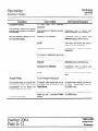
PREFACE . . . . . . . . . . . . . . .,.,,, sI. . . . . . . . . .. .. .. . . .. .. . . . . . . . . . . . . . . . . . . . . . . . . .. . . s. . . . . . . . . . . . . . i . . . . .~......................................,.....,...,.......
Intro-1
.., ,, ,......... . . . .. . . .. .. .. . . . . .‘. . . . . . . . . . . . . . . . . . . . . . . . . . . . . .. . . . . . . . . . . .. .. . . .. . . . . . . ,.,. .,.. ..Inno-1
ABOUT THIS CHAPTER.. . . .:.. .
QUICK-REFERENCE CHART.. . . . . . . . . . . . . . . . .. .. . . . . . . . . . . . . . . , . . . . . . . . . . . . . . . . . . . . .. . . .. . . . . . . . .. . . . . Intro-2
Section A - FCC Requirements
RADIO AND TELEVISION INTERFERENCE ......................................................................................................
HEARING AID COMPATIBILITY .......................................................................................................................
RESPONSIBILITIES ...... ....................................................................................................................................
User Responsibilities .....................................................................................................................................
Telco Responsibilities ....................................................................................................................................
Section g’-
A- 1
A- 1
A-2
A-2
A-2
System Components
STANDARD COMPONENTS., ............................................................................................................................
One Master Key Service Unit (KSU) .............................................
.: ..................................................................
One Expander KSU. .............................................
.:. ......................................................................................
Up to Sixty-Four Telephone Sets......................................................................................................................
Up to Twenty-Eight DSS/BLF Units., ..............................................................................................................
OPTIONAL COMPONENTS., ..............................................................................................................................
Up to Two Door Answer Units ........................................................................................................................
Up to Five Power Fail Transfer Units., ..........................................................................
). ..................................
../ ........... ~‘;.;. ...........................
Up to 63 Off Premises Extension/Data Interface (OPX) unit+ ..................................
,One Station Message Detail Recorder (SMDR) Unit., ........... ..-......... ;. .:. ...... .;, ........ .:. ...... ..:. ......... ..:. ......... ,: ............
SetStanhs/Wall-Mounts ............. . ...... l...................:.
... ..- ........ ................................
.: ............... . ........ ‘.I ..............
Desigrtation Cards., ........................................................................
I.. ...... .;. ........................ :. ... .;. .......................
B- 1
B- 1
B-2
B-2
B-3
B-3
B-3
B-3
B-4
B-4
B-4
B-5
Section C - Technical Specifications
.
CONNEmORS ..................................................................................................................................................
POWER FAIL TRANSFER UNIT CONNECTORS (Optional) .....................................................................................
SMDR UNIT (Optional) ......................................................................................................................................
ENVIRONMENTAL
REQUIREMENTS ................................................................................................................
POWER REQUIREMENTS ..................................................................................................................................
STATION NUMBERING PLAN.. .........................................................................................................................
SYSTEM CAPABILITIES., .................................................................................................................................
C-l
c-2
C-2
C-2
C-3
C-3
C-3
Section D - Connection Procedures
STEP 1:
INSTALLING THE KSU ...................................................................................................................
Site Preparation. ...........................................................................................................................................
Backboard Installation,, ................................................................................................................................
System Uncrating .........................................................................................................................................
Master KSU Installation ................................................................................................................................
Expander KSU Installation ............................................................................................................................
TRILLIUM
Telephone
Systems
D-l
D-l
D-l
D- 1
D- 1
D-2
Panther 2064
Page i
Technical
Service
Manual
Table of
Contents
>
Topic
,;
I
Page
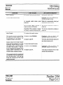
Section D -
Connection Procedures (continued)
CONNECTING INCOMING TELEPHONE LINES . . ............... ;: ....................................................
. ....... :D22
- STEP2:
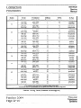
Incoming Line Wiring Table (Lines 1 through 10). ..............................................................................................
D-3
Incoming Line Wiring Table (Lines 11 through 20). ............................................................................................
D-4
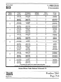
INSTALLING STATION WIRING ..... . . ............................................................................................
STEP 3:
D-6
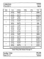
Station Wing Table (Stations 10 through 17). ...................................................................................................
D-7
Station Wiring Table (Stations 18 through 25). ...................................................................................................
D-8
Station Wiring Table (Stations 26 through 33) ....................................................................................................
D-9
Station Wiring Table (Stations 34 through 41). .................................................................................................
D-10
Station Wiring Table (Stations 42 through 49). .................................................................................................
D-l 1
Station Wiring Table (Stations 50 through 57) ..................................................................................................
D-12
Station Wiring Table (Stations 58 through 65). ........................
. ........................................................................
D-13
Station Wiring Table (Stations 66 through 73). .................................................................................................
D-14
STEP 4:
CONDUCTING THE INITIAL SYSTEM AND STATION TESTS.. ........................................................
D-15
CONNECTING THE BACKUP BATTERY ........................................................................................
D-15
STEP 5:
,:, .... D-16
STEP 6:
CONNECTING DOOR ANSWER UNIT AND DOOR MODULES ..................................................
Door Answer Unit Installation ........................................................
:. ............................................................
D- 16
Door Module Installation ........................................
. ....................................................................................
D-16
Door Answer Unit Test.. .............................................................................................................................
D-17
STEP 7:
CQNNECXING THE MUSIC SOURCE .............................................................................................
D-18
Music Connection .....................
:..................................................................................................................
D-18 $
Music
Test
.....
:.:
..:.
..............
.
................
.
....
.:,.
...........
.
............
.
.....
.
.......
.
.....
::
...
.
*
......
.+
...
.
.......
.
.........
.
................
D;18.
.
CONNECTING THE EXTERNAL PAGING EQUIPMENT.. ................ .:. ...........................
.:. ................. D-19
STEP 8:
Equipment Connection ......................................................
.: .........................................................................
D-19
Paging Test.. .......... (............. .......................................................................................................................
D-19
STEP 9:’
..
CONNECTING AN EXTERNAL LOUD BELL ..............................................................................
.: .. D-20
Equipment Connection ................................................................................................................................
D-20
Loud Bell Test ....... .: ..................................................................................................................................
D-20
STEP 10:
CONNECTING THE OPX UNIT, .....................................................................................................
D-2 1
OPX Unit Connection,, ..............................................................................................................................
D-21
OPX Unit Test ...........................................................................................................................................
D-21
STEP 11:
CONNJXTING THE SMDR INTERFACE UNIT ................................................................................
D-22
SMDR Interface Unit Installation., ...............................................................................................................
D-22
SMDR Interface Unit Test.. .........................................................................................................................
D-22
SMDR Printout Formats ..............................................................................................................................
D-22
STEP 12: CONNECTING THE POWER FAIL TRANSFER UNITS ......................................................................
D-23
Power Fail Transfer Unit Installation ..............................................................................................................
D-23
Power Fail Transfer Unit Test .......................................................................................................................
D-27
STEP 13:
INSTALLING AN EXTERNAL AMPLIFIER .....................................................................................
D-28
Panther 2064
Page ii
,i
TRILLIUM a -Telephone
Systems
Technical
Service
Manual
:::::::::::::::::::
j:
::::,:::
~
Table of
Contents
:::::::::::::::::::::
i
~~~~.~“..“..........
.
. . .
. .
. .
. .
.
. .
. .
.
_.... . . .
. . . . . . . . .
. ..~.....................
.
. .
. .
. .
.
.
. . .
. . . . .
:‘........
. .
. .
.
. .
‘ .
. .
. .
. .
. .
. . .
.
.
. . .
. . .
. .
. .
. .
. .
.
.
. . . . .
. . . . .
.
.
. .
. .
. . . . .
. . . . .
. .
. .
. .
. .
.
.
. .
. .
. .
. .
.
.
. .
. .
. .
. .
. .
...
.
.
. .
. .
. .
. .
. .
. .
.
.
. .
. .
. .
. .
. -.... . . . .
.
. .
. .
. .
. .
. .
. .
. .
. .
.
.
.
.
. . .
. . .
. . .
. . .
.
.
. ..-................
. . . . . . . . .
. .
. .
.
. .
.
_ . . . ..__....__..._...~..~.~..~~~~~~~~.~~.
. . ...............
_ ._......_....._._,...........-.-
_ __..
I
. .._. ........_. _. .
.. . _
,
.
Page
Topic
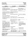
Section E -
System and Set Layout
. ... .._....... E-l
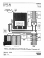
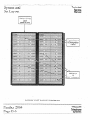
TYPICAL MASTER KSU LAYOUT DIAGRAM (Standard Components only) ..................................................
E-2
TYPICAL MASTER KSU LAYOUT DIAGRAM (Standard Components bnly). ..............................................................
E-3
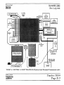
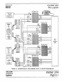
TYPICAL SYSTEM LAYOUT DIAGRAM (Optional and External Components only). ...................................................
E-4
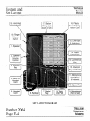
SET LAYOUT DIAGRAM. ..................................................................................................................................
SET LAYOUT. ...................................................................................................................................................
E-5
DSS/BLF UNIT LAYOUT DIAG RAM. ..................................................................................................................
E-6
TYPICAL POWER FAIL TRANSFER UNIT LAYOUT DIAGRAM ..........................................................................
E-7
Section F -
Feature Programming
F-l
I.. ...........................................................
FEATURE CATEGORIES ......................................................................
:
F-l
.........................................
Categories Versus Codes,, ....................................................................................
F-l
Referencing Categories to Codes.. ...................................................................................................................
F-l
Interrelated Features .......................................................................................................................................
F-2
Feature Programming Cross-Reference Table,. ....................................................................................................
:. ..................................
F4
SYSTEM-WIDE FEATURES ..... . . .....................................................................................
System-Wide Feature Programming Table .........................................................................................................
F-5
F-10
INDIVIDUAL SET FEATURES ..........................................................................................................................
F-11
Individual Set Feature Programming Table ......................................................................................................
F-14
INDIVIDUAL LINE FEATURES .........................................................................................................................
F-15
Individual Line Feature Programming Table ......................................................................................................
*, ..........................................................................
F-18.
INDIVIDUALGROUP
FEATURES ................................................
. ..i.. ............................
.I ......... :: ..:. ....... . ........ l....‘.....:. .... :.......‘.......:. ... ‘F-19
IndividualGroup&at&ProgramkngTable
F-20
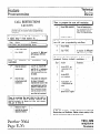
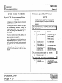
CALL RESTRICTIONS ......................................................................................................................................
F-21
Call Restiction Feature Programming Table .. .I ......................... :. .......................................................................
:. .................................................
F-22
Yerifying Call Restrictions. .........................................................................
.: .....................................................................................
F-24
SPEED CALL NUMBERS.. ...........................................
F-24
Speed Call Programming Notes.. ....................................................................................................................
F-24
Common Speed Call Numbers .......................................................................................................................
F-25
Private Speed Call Numbers ..........................................................................................................................
F-2.5
FEATURE DESCRIPTIONS .....................
:. ........................................................................................................
Section G OPERATING lNSTRUCTIONS
TABLE..
Operating Instructions
. .. . . ., , .~. . . . . . . . . . . . . . . . . . . . . . . . . . . . .. . . . . . . . . .. .. . .
Section H TROUBLESHOOTING
TRILLIUM
Telephone
Systems
. . . . .. . , . .. . ,. . . . .., G-l
Troubleshooting
TABLE ,,,,,,,.,,...,.....,.,.,............1..,,.....I.....I...I.I..,~I.............I.II.......I.......,.,.,,,,,.,,.,,,,,,,.,..,,.
H-l
Panther 2064
Page iii .
Technical ’
Service
Manual
:!;
::::::::::::::::::::::::::::::::::::::::::::::::::::::::::::::::
Chapter
Introduction
: ::::::::::::::::::::::
::::::::::::::::::I::::::::::::::::;:::::::::::::::.....
. . . . . . . . . . . . . . . . . . . . . . ----*...*
. . . . . . . . . . . . . . . . . -.--,..-..*
..: . . . . . . . . . . . . . . . . . . . . . . . . . . . . . . . . . . . y.......................
. . . . . . . . . . . . . . . . . . . . . . . . . . . . . . . . . . . . . . ..-..........................
a. . . . . . . . . . . . . . . . . . . . . . . . . . . . . . . . . . . . . . . . . . . . . . . . . . . . . . . . . . . . _ . . . .
a
.
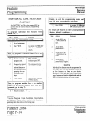
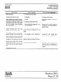
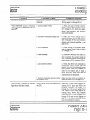
PREFACE
ABOUT, THIS CHAPTER.
The Panther 2.064 Electronic Key Telephone System is a
state-of-the-art system that incorporates sophisticated electronics to meet the communications needs of today’s office
and business user.
This chapter has also been designed specifically to enable
technicians to install, operate, and maintain the Panther 2064
Electronic Key Telephone System. Information is presented
in a logical order, without undue wordiness - to help the
technician find, understand, and use the relevant information, quickly and easily.
It connects up to 20 outside tone or rotary telephone lines
(one or two optional Door Answer Units and Door Modules
may be installed reducing the number of outside lines served
on a l-for-l basis) with up to 64 station Sets - which are
all wired in a star configuration. The master key service unit
(KSU) can handle 10 outside lines and 32 internal stations;
with the expander KSU, the system can handle its full complement of outside lines and internal stations. Both
Handsfree and Non-Ha&free
Sets are available. A separate
Direct Station Select/Busy Lamp Field @SS/BLF) Unit is
available for use at an attendant station; it contains station
select keys and indicators that show the status of all system
stations.
Attendant calling, common and private speed calling, call
transferring, transfer ringing, door answering (with optional
Door Answer Units and Door Modules), conferencing (up to
3 parties), message waiting, internal intercom paging (station-to-station;
zone, and all page paging), .external
ioudspeaker paging, call detail and account code recording
(through an optional SMDR unit), and last number redialing
are just some of the many features offered.
In addition, the Panther system is designed to allow easy interfacing with modems and answering devices through an
optional OPX device.
The fully sealed Panther 2064 Electronic Key Telephone
System may be installed in either a standalone mode or behind a CENTREX or PBX.
Therefore, for example, the Connection Procedures are separated into concise steps that have a logical and necessary
sequence; and reference material (Technical Specifications,
Feature Programming,
Operating Instructions,
and
Troubleshooting) is presented in a variety of easy-to-follow,
visible-at-a-glance tabular formats.
To acquaint yourself with this chapter, please review the
Table of Contents and spend a few moments browsing
through the different sections.
CAUTION
Panther equipment is sealed. Breaking the seal
will void your warranty.
.
If you have an installation, operation, or troubleshooting
problem that you cannot solve by using thischapter (and ‘.
that your dealer cannot help solve),. call TRILLIUM
Customer Service at 1-800-848-2444 (inside California, call
1-800-422-7600).
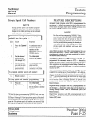
NOTE
For your ready reference, a chart summarizing
indicator signals appears on the back of this
page.
An optional external backup 24 V battery can be connected
to each KSU in the system: the backup batteries are automatically brought on line in the event of a power failure,
thus preventing interruptions in telephone service.
Also, in the event of a total system failure, incoming lines
will be transferred to standard sets if optional Power
Transfer Units have been installed in the system.
TRILLIUM
Telephone
Systems
Panther 2064
Page Intro- 1
Technical
Chapter
Service
Manual
’ Introduction,
....................*
*..............................,,....................................................:::::
:::::
:;:;
:;:;
:::::i::::::::;::::l::
:::::i::::::::;::::l::
::::
::::
:::::::::;::::::::::::::::::::::::::::
:::::;::::::::::::::::
::::!:
::::!:
::::::
::::::*
:::::::I::~:::::::::(:::::::::::::::::::::::::::::::::::::::::::~::::::::::::::::::::::::::::
:::::::I::~:::::::::(:::::::::::::::::::::::::::::::::::::::::::~::::::::::::::::::::::::::::::::~:::::::::::::::::::::::
.
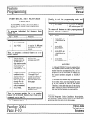
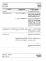
QUICK-REFERENCE
CHART
The Panther 2064 Electronic Key Telephone System lets
users know what is happening .with calis and lines through a
series of indicator patterns. These indications are summarized in the chart on this page. Specific indications are
described at the appropriate places throughout the procedural material in this chapter.
Lii
hdlcatar
Action
Lii
OFF
stahts
I
line ide
-:
._
-
ON
pw...“..,- -c.w.-.
... . ;.-.,... M,......v....c ...I *v. . ...w i-1
. .. .. .. y.” . .. . ._.I.. _.. . .. .. . .. ..Y” . . .. . .. .. .. . .. ..- A..r.r.m 0
-
Slow WINKING
.I.. F,.ll..*l.,- (..,.,,- ..-- ...! . .. ..--.......__..........-..-.!.
,:_
i-i
::
-: .,.,.......,....... . . .. . .. . .i.- -: . . .. .. . .. .. . .. .. ..\.....\.... i I
I
Vq dor, FIASWG
..I ,,.,...
.
.:,- >.,.!y..,.I
..vIIU”
_:
+
.+
L
...-....-...~.
..,.
‘+-Y-~oy”SHlNG
. . .. . . .
2
:.: .. .. .. . .I
, I *
:::::::::::::::::::::::::::::::::::::::::::::z
,t.!..:.,
_:
&
&,..,.“..L
’ t *
. .. .-....!...:.,.
-I’
i;-y-e+-. -
,:..!I,
-;
‘L
.&...-I
* I *
::::::::;
:::::::::::::::;
1 cLluw/r2064
Page.Intro-2
PQnthPl
....\ ..1..,..,
:>
-)
“;..~~‘~
I
1 Llnain”samm‘
exdtie
hold a
1 motwstadm
I
I
/ LiwinuseatyarSet
.
‘
1, tin, on erdusive hdd
at you set; line ualsfelledbaa to y~~sei:
I
or c&a& lo you set
lnmrmgd
:::::::::::::::::::::::::::::::::::::::..................................................................................................................................................................
. . . . . . . . . . . . . . . . . . . . . . . . . . . . . . . . . . . . . . . . . . . . . . . . . . . . . . . . . . . . . . . . . . . . . . . . . . . . . . . . . . . . . . . . * . . . . . . . . . . . . . . . . * . . . . . . . . . . . . . . . . . . . . .....
* .........,..........,.........
TRILLIUM ‘x._
Telephone
Systems
~ - -
Technical
Service
Manual
.
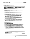
WARNING
The Panther 2064 Elecnonic Key Telephone
System generates and uses radio-frequency energy and - if not installed and used in strict
accordance with these instructions - may
cause interference to radio and television
reception.
The Panther 2064 Electronic Key Telephone System has
been certified to comply with the limits for a Class B com, puting device, pursuant to Subpart J of Part 15 of the Federal
Communications Commission (FCC) Rules which are designed to provide reasonable protection from radio and
television interference in a residential installation. However
there is no guarantee that interference will not occur in a
particular installation.
If interference is encountered, test to determine if the unit is
at fault by unplugging the Key Service Unit (KSU) from the
wall outlet.
‘If unplugging the KSU removes ‘the interference, try the foil
lowing corrective measures, singly or .in combination, until
the interference is eliminated:
.
Change the location or position of the indoor receiving antenna of the radio or television.
.
Relocate the Panther 2064 Set or KSU in relation to
the radio and television receivers experiencing
interference.
.
Plug the KSU into an outlet that does not also serve
radio or television sets.
If further help is needed, consult your TRILLIUM dealer or
an experienced radio/television technician - or refer to the
FCC’s booklet, “How to Identify and Resolve Radio-TV
Interference Problems.‘* It is available from the US
Government Printing Office, Washington, DC 20402 (stock
number 004400403454).
TRILLIUM
Telephone
Systems
.
.
.
.
-
.
.
.
.
.
.
.
.
.
.
.
.
. . . _ ”
.
.
.
.
.
.
.
ii..
FCC
RADIO AND TELEVISION
INTERFERENCE
I’
- - - - -
Requirements,
HEARING AID COMPATIBILITY
The Panther 2064 Set is compatible for those requiring a
hearing aid as defined in section 68.316, Part 68 of FCC
Rules.
._._._....,......................................................,......................................................................................................................................
. . . . . . . . . . . . . . . . . . . . . . . . . . . . . . . . . . . . . . . . . . . . . . . . . . . . . . . . . . . . . . . . . . . . . . . . . . . . .I..
a . . . . . . . . . . . . . . . . . . . . . . . . . . . . . . . . . . . . . . . . . . . . . . . . . . . . . . . . _ _......_...... . . . . . . .
. . . . . . . . . . . . . . . . . . . . . . . . . . . . . . . . . . . . . . . . . . . . . . . . . . . . . . . . . . . . . . . . . . . . . . . . . . . . . . . . . . . . . . . . . . . . . . . . . . . . . . . . . . . . . . . . . . . . . . . . . . . . . . . . . . . . . . . . . . . . . . . . . . . . . . . . . . . . . . . . . . . . . . . . . . . . . . . . . . . ......
Technical
Service
Manual
.
........”.........~............*.........................................::::::::::::::::::::::::::,::::::::::::::::::::;:~::::;;:::~::::::::~:::::::::::::::::~:::~:::::~::~:::::~
,
FCC
Requirements ........
.................................................................$.
.
’
RESPONSIBILITIES
.
The FCC’s rules permit the Panther 2064 Electronic Key
Telephone System to be connected to the telephone network
via a jack or jacks provided by the telephone company
(telco). These jacks are not provided for coin or party lines.
Telco Responsibilities
The telephone company is required to give you adequate notice of any changes it makes in its .technical operations or
procedures that may affect the compatibility or use of your
Panther 2064 Electronic Key Telephone System.
User Responsibilities
Before connecting your Panther 2064 Electronic Key
Telephone System to the telephone lines, you must contact
the telephone company and provide them with the following
information:
.
Telephone numbers of the lines to which the
Panther 2064 Electronic Key Telephone System is
to be connected (lines 1 through 20)
.
FCC Registration Number (found on the side of the
Key Service Unit or KSU: the number for the
Panther 2064 system - with or without the expander KSU - is EBS78T-71737-KF-E)
.
Ringer Equivalence Number (also found on the side
of the KSU: the number for the Panther 2064, with
‘or without,the expander KSU, is 33B)* i
.
USOC jacks required (usually one !O-conductor
RI21 jack to each KSU; therefore, h~o RI21 jacks
are required if the expander KSU is installed )
.
Facility Interface Code (the code for the Panther
2064 Electronic Key Telephone System is 02LS2)’
l
Service Code (the code for the Panther 2064
Electronic Key Telephone System is 9.OF)
You also have the responsibility to disconnect a malfunctioning Panther 2064 Electronic Key Telephone System
from the telephone lines until the cause of the malfunctioning is identified and repaired. Otherwise, the telephone
company may temporarily disconnect service.
* The Canadian Department of Communications load number for the Panther 2064 Electronic Key Telephone System
is 16B.
Panther 2064
Page A-2
TRILLIUM i. Telephone.
Systems
.........................................................................................................
....................................................................................................
.....
. . . . . . . . . . . . . . . . . . . . . . . . . . . . . . . . . . . . . . . . . . . . . . . . . . . . . . . . . . . . . . . . . . . . . . . . . . . . . . . . . . . . . . . . . . . . . . . . . . . . . . . . . . . . . . . . . . . :::::::::::::::::::::::::::::::::::::::::~::::::::::
Technical
System
Service
Manual
Components.
,......_..____......................................
......................................................................................................................I..................................................................
:
.................,..,...
................................................,.......................
.....................a....-...
~....................................................................................a
....................................................2.y..
.
One Expander KSU
Part Number 90-0287 (tone/rotary)
The expander (KSU for the Panther 2064 Electronic Key
Telephone System can also be programmed to operate with
either DTMF or rotary (pulse) signaling. The signaling on
each CO line can be programmed independently.
The expander KSU has one 50-pin connector on its right
side (labeled CO11 to CO20) to attach ten more incoming
telco CO lines (line 20 must be left vacant if a second optional Door Answer Unit is insta.lIed).
Also on the right side of the master KSU are connectors labeled POWER FAIL (used for the optional Power Fail
Transfer Unit), and DOOR (used for the optional Door
Answer Unit).
Near the bottom left of the expander KSU are four 50-pin
connectors, labeled STATIONS 42 TO 49,50 TO 57.58 TO
65, and 66 TO 73 that are used to connect the KSU to the
station wiring main distribution frame (MDF) - and,
through the MDF, to stations 42 through 73.
Two connectors are available at the bottom of the expander
KSU that are used to con&t it to the master KSU.
The expander KSU has its own separate power cord ‘(at the
top of the KSU) that plugs into a 110 V ac outlet (but only at
the appropriate time; ‘see the Connection Procedures section). A separate grounding wire (12 AWG, solid copper)
which connects to the top of the expander KSU must be attached to a ground clamp, usually on a water pipe.
Up to Sixty-Four Telephone Sets
Part Number 90-Q288
(non-handsfree)
.
Ert Number 90-0225
(handsfree)
Other than the handsfree operation, these two models look
alike and operate identically. For example, both have an attractive black matte finish.
Each Set’s base has twenty line select keys (labeled 1
through 20). eight dedicated function keys (labeled .Hold,
Flash/Cancel, Conference, Intercom, Redial, Speed,
Speaker, and Mic.on/off) and a tone dial keypad
The line keys, the Intercom key, and the Mic.on/off
have accompanying status indicators.
key
Finally, the base has a speaker volume control (a sliding adjustment) and a ringer control switch (a 3-position switch,
for low, medium, and high volume ringing).
.’ Each Set also includes a telephone handset and two .modular
cords - a 4;conductor, coiled cord for connecting the handset to the Set, and a 4-conductor modular cord for.
connecting the Set to the station wiring jack.
ifs ,,
’
An input connector (labeled EXTERNAL BATTERY) for a
separate 24 V dc backup battery is also provided at the top
of the expander KSU. If ac power is lost, the switchover to
battery power is automatic when the optional backup battery
for the expander KSU is connected
The unit comes a mounting bracket and four screws for installing the expander KSU over (in front of) the master KSU
(on the backboard).
Panther 2064
Page B-2
TRILLIUM t _
Telephone
Systems
::::::::::::::::::::::::::::::::::::::::::::::::::::::::::::::::::::
:u:::::::::;
:::::::::
::::::::::::::
::::::;
. . . . . . . . . . . . . . . . . . . . . . . . . . . . . . . . . . . . . . . . . . . . . . . . . . . . . . . . . . . . . . . . . . . . . . . . . . . . . . . . . . . . . . . . . . . . . . . . . . . . . . . . . . . . . . . . . . ................-.-..-___.. . . .. . . .. . . . . .. . . . . . . . . . . . . . . . . . . . . . . . . . . . . . . . . . . . . . . . . . . . . . . . . . . . . . . . . . . . . . . . . . . . . . . . . . . . . . . . . . . . . . . . . . . . . . . . . . , . . . . . . . . . . . . . . . . .......................-...-
Technical
Service
Manual
_
............_...............................................
....,.i
....::::
........“...
...............................................................................................................*
System
Compdnents
::::::::::::::,:::::::::::::::::::::::::::::::::::
Up to Twenty-Eight DSS/BLF Units
Part Number 90-0226
The DSS/BLF utiit has 64 keys and indicators, labeled 10
through 73 - one for each possible station in the system.
The D_CC,‘!!?T.F*:+.-Set. pa& (also kcown BS attendant station sets - but not to be confused with the master station)
allow the user/attendant to select the desired station by
pressing one of the 64 direct station select (DSS) keys and to
observe the status of each station by observing the corresponding busy lamp field (BLF) indicator.
The DSS keys can also be programmed to select speed call
numbers - keys 10 through 19 can be used to dial the first
ten of the attendant’s private speed call numbers; and keys
20 through 73 can be used to dial the corresponding first 54
of the system’s 80 common speed call numbers (codes 20
through 73).
These units - which require an accompanying Set - are
assigned a station number and, therefore, reduce the maximum number of sets possible on a l-for-l basis.
For example; a system with.a single DSVJ3LF unit
5 colild have ,a m&mum of 63 S&s (including the Set
paired with the DSS/BLF.unit).
Alternatively, a system could have as many as 28 DSS/
BLF units, all reqdiring an accompanying Set; this system would have 36 Sets, 28. of which would be part of
an attendant station.
Each DSS/BLF unit includes a 4conductor modular cord for
connecting the unit to the station wiring jack..
Each DSQ’BLF unit also comes equipped with a Designation
Card (used to record station locations/assignments) - and
with a plastic cover that protects the Designation Card.
TRILLIUM
Telephone
Systems
.
OPTIONAL COMPONENTS
Up to Two Door Answer Units,
Part Number 90YO058,
With One or Two Door Modules Each,
Part Number 90-0057
The Door Answer Unit (also known as the Door Answer
Control) is installed next to, and connects with, the KSU. It
serves as the interface between the system’s stations and the
one or two installed Door Modules (also know as the Door
Answer Boxes) at the desired doors or entryways. The first
Door Answer Unit uses line IO and the second, if instiled,
uses line 20.
Together, the Door Answer Units and iheir corresponding
Door Modules enable signaling and conversation between
Set users and visitors. Like the KSUs, all these units come
equipped with mounting Screws.
A visitor, by pressing the door bell button on a Door
Module, generates a distinctive tone (four groups of 4 short
tones for Door Module 1, four groups of 2 long tones for
Door Module 2) that will sound at all Sets programmed to
- ring on, line 10. or 20 and line 10 or line 20. indicator
WINKS, depending on which line the coqesponding- poor
Answer Unit is installed on. Also, each Set user can gencntc
a calling tone that will sound at Door Module 1 only.
Up to Five Power Fail Transfer Units
Part Number 90-0052
The Power Fail Transfer Unit automatically takes over in the
event of an electrical power failure, allowing for continued
telephone service during the emergency. One Power Fail
Transfer Unit can handle up to 4 incoming lines.
When power fails, the Power Fail Transfer Units transfer incoming CO lines (up to all 20 of them - or the 18 or 14,
lines in use, if the optional Door Answer Units with Door
Modules are installed) to pre-installed standard telephone
sets (not to Panther 2064 Sets).
Panther 2064
Page B-3;:::,:*:
..........................................................:::::::y::::::::::::::::
:::::::::::::::
c:::::.;
:::::::::::::::::::::::::::::
“$”
.::::::::::::::::::::;
:::::::::::::::::::::::
.
System
.
Components
Technical
Service
Manual
,
.’
. . . . . . . . . . . . . E . . . . . . . . . . . . . . . . . . . . . . . . . . . . . . . . . . . . . . . . . . . . . . . . . . . . . . . . . . . . . . . . . . . . . . . . . . . . . . . . . . c . . . . . . . . . . . . . . . . . . . . . . . . . . . . . . . . . . . . . . . . . . . . . . . . . . . . . . . . . . . . . . . . . . . . . . . . . . . . . . ” . . . . . . . . . . . . . . . . . . . . . . . . . . . . .................................................................
,............
. . . . . . . . . . . . . . . . . . . . . . . . . . . . . . . . . . . . . . . . . . . . . . . . . . . . . . . . . . . . . . . . . . . . . . . . . . . . . . . . . . . . . . . . . . . . . . . . . . . . . . . . . . . . . . . . . . . . . . . . . . .....................................-................................................................................................
a
.
I.
.
Up to 63 Off Premises Extension/
Data Interface (OPX) units
Part Number 90-0308
The OPX unit converts a 4-wire interface to a 2-wire interface, allowing a single line telephone to be connected to any
spare station jack - except station 10. It also allows 2-wire
devices to be connected at a distance greater than the system
2000 feet limit for Sets. The OPX unit also simulates CO
line characteristics, allowing a modem or an answering ma-.
chine to be connected to the system. Finally, the OPX unit
allows a remote device to be connected to your system at
any distance via a CO line.
Set Stands/Wall-Mounts
Part Number 90-0087
Each Set may be placed on a desk - or mounted on a wall
using the Set Stand/Wall-Mount Bracket (available in packages of 10).
The same bracket can also be used to provide a heightened
viewing angle when used with the Set on a desk- or tabletop.
When the user lifts the single-line telephone’s handset, an intercom connection is made to the Panther system. Also, by
dialing a special code, the off-premise user can access any
of the Panther system’s outside lines.
One Station Message Detail Recorder
(SMDR) Unit
Part Number 90-0227 only
-
. This unit ‘allows information .on system, line, and station’
usage to be captured and recorded.
Panther 2064
Page B-4
TRILLIUM f,,
Telephone
Systems
......................................,...............................,..............................................
..........................___._.
..................................._._..
........_._...........:_.
_..........__.
........................................................................................................................................................................................................................................................................
...............
Technical
Service
Manual
System
Components
........”
................................i................I.-...............................
..............................................
....................................................
:....................,...
--:=
Designation Cards
Part Number 90-0300
(for Panther 2064 Sets)
and
Part Number 90-0301
(for DSS/BLF units)
The Designation Card for Sets (the same Designation Card
is used for both non-handsfree and handsfree Sets) is used to
list the telephone numbers of the incoming lines.
The Designation Card for DSS/BLF units is used to itiy
the assignment or location of the’64 system stations irznbered 10 through 73) and for recording speed call nurnkrs
- the first 10 private numbers in spaces 10 through 1Srand
the fust 54 common numbers in spaces 20 through 73.
”
Although each DSS/BLF unit comes equipped with oxz installed and one spare Designation Card, you may cxder
additional cards (in packages of 10) for your system.
Notice that the Set and the DSS/BLF unit use d#uenf
Designation Cards.
Although each Set comes equipped with one installed and
one spare Designation Card, you may order additional cards
(in packages of 10) for your system.
TRILLIUM
Telephone
Systems
Panther 2064
Page
B-5
”....”
**‘*:s~
::::
......................................................
”...............................
....-.
“”.................
,.....”
....,..
.................-........................*............................................................................
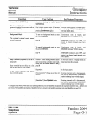
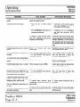
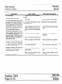
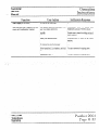
To use most of the PANTHER 2064 System
features, follow the operating instructions
given in
the PANTHER User Guide and Quick Reference
Guide. This update sheet describes all features
which operate differently
and outlines new features
that have been added.
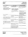
Private Speed Call - Dialing
TO SPEED
l
CALL
A PRIVATE
Llfi the handset,
then
Handsfree
Turn
Handsfree
Press
NUMBER
press
the MIC
l
the Line key of an outsIde
on/ofl
lndlcator
e
Press
l
Dial Vie desired
The
!:ne or press
Call Code
(00 to 101.
IS automatically
speed
l
Press
the Speed
Continuous
l
Dial the desired
l
Dlat the entry
0 Press
IS heard.
speed
call code
to be stored
MaxImum
26 dqts.
Contmuous
tone
the Line
key of an outslde
line.
Turn the MIC. on/off indtcator
on.
Press the Line key of an outsbde line or pfess
9
mcludlng
any pauses,
halls,
Rashes.
ON THE
For the
stops.
l
Press
the Speed
key.
0 Dial the desired two-dlglt speed call code (20 to 99).
The telephone
number IS automatlcally
dlaled.
(00 to 10).
l
the Speaker
press
NUMBER
Dial tone IS heard.
Write the entry on the deslgnatjon
card.
Repeat the above procedure
for each entry
l
Llh the handset,
Handsfree
Hanasfree
Set
key.
tone
Speed Call - Dialing
TO SPEED CALL A COMMON
ON THE 1032/2064
Set
dlaIed.
Private Speed Call - Storing
1032’2064
card
9
l
Operation
the entry on the deslgnatlon
the Speaker
key
Common
Speed
number
Write
Press
on.
the Lme key of an outsIde
Dial tone IS heard.
the Speed key.
l
l
l
to be stored
key to stop storing.
1032’2064
first
A-t-rENDANT
22/54
LI~I the handset;
numbers
press
Handsfree
- Turn
Handsfree
- Press
the Line key of an outslde
the MC. on/off
indicator
Ime.
on.
the Lme key of an outs&
line or press
9
Dial tone IS heard.
Operation
l
103Z2064
Press
Attendant
the Speed
key.
Continuous
tone
IS heard;
0
Press the desired
l
Dial the entry to be stored
Maximum
26 dlgits.
Speed
to store
the first
Intercom
Indcator
10 numbers
l
73
wrnks.
Press
The number
For the
Contmuous
l
Write
lone
Ihe entry
l
Repeat
l
Press
above
pauses,
halts.
flashes.
stops.
on the desgnation
procedure
the Speaker
any
entry
last
58126
l
l
l
Press
Dti
1032/2064
Attendant
press
0 Press
the Speed
key.
Continuous
tone IS heard;
to store
Intercom
the
11th
Indicator
number
- Press
winks.
Dial the entry
TO END
to be stored
Maximum
26 dIgits.
Continuous
tone
mcludmg
stops.
any
pauses,
l-al&,
%shes.
l
20 -
Hang
the Speed
key
Handsfree
THE
dialed
lndlcator
two-dlglt
speed
call code
Ime.
on.
the Line key of an outs&?
heard.
74 - 99 on the
speed
the Lme key of an outside
Dial lone IS
line or press
(42 - 99 on the
2064).
The telephone
10.
1032;
numbers
the MIC. on/off
- Turn
0 Dlat the desired
Operation
IS automallcally
0 Llh the handset;
(0 be stored.
storing.
Call key (20 - 41 on the
Hanasfree
Handsfree
card.
for each
key to stop
Speed
on the 2064).
Call key (10-19)
lncludlng
the desired
number
IS automattcally
CALL
up the nandset.
Press
the Speaker
key.
dialed.
9
Common
l
Press
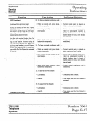
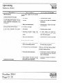
NEW FEATURES
Speed Call - Storing
Transfer
the Speed
key at slalion
10
Conr~nuous
lone IS heard;
~nlercom
. D,JI :W J~-WN
2-dIgIt
speed
mdlcator
0 Answer
Call COCK? (20-99)
Intercom
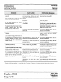
Paging - To All Stations
TO
SETS
l
ALL
Lift the handset
Handsfree
l Dial 80.
the MIC. on/off
Double lone IS heard;
your announcemenr.
Make
l
Turn
the Intercom
key.
indtcator
Intercom
on.
lndlcalor
l
Handsfree
Ihe intercom
wmks.
the MIC. on/off
Indicator
on; press
Dial rhe desired
zone number (81 to 95).
Triple tone is heard; Intercom
lndlcator
l
Make
on; press
Make
your
press the
call.
If off-hook,
press
the MIC. on/off
key.
lndlcator
the Intercom
tone
IS heard;
intercom
indicator
party’s
wmks.
While
Paging
press
Handsfree
the MIC. on/off
Turn
Conanuous
flashmg
length
of time.
lme key.
from
the application
of
you are callmg
IS busy,
nngmg
IS heard
over
the called
speaker.
tone
l
key.
indicator
IS heard;
burst
TO
A CAMP-ON
on a call, if you
intercom
on; press
Indicator
the fntercom
key.
winks.
If handsfree,
transferred
press
SIGNAL
hear three
short
your
bursts
of tone
through
your
first ca!l on hold.
the 9 key to be aulomatlcalty
connected
to the
call.
OR
l
If off-hook,
press
the flashmg
line key.
IS heard.
announcement
TRILLIUM
tek$eone
sy*.ems
@
Specrhcabons
U.S.
a programmable
the appropriate
set’s speaker:
l Press the Hold key to place
the Intercom
tone
A double
your
after
announcement.
0 Loft the handset;
Make
not answer
key.
TOMAKEALOUDSPEAKERANNOUNCEMENT
l
iO
connected
lme key.
IS an automatic
feature derived
Rlngmg, as described
above.
If the statlon
Loudspeaker
Dial 99.
CALL
key to be aulomatlcally
the flashing
does
TO RESPOND
l
9
nnglng returns to your set.
l To pick up the call, press
Camp-on
Transfer
key.
l
A TRANSFERRED
Camp-On
Handsfree
Dial 80
Double
stallon.
wllh one
wtnks.
TO PAGE ALL ZONES
SIMULTANEOUSLY
l Loft the handset
and press the Intercom
l
the Intercom
announcement.
Turn
f;r Lhc desired
IS dlalcd.
0 If handsfree,
the transferred
If the station
key.
l
your
(1 O-731
key II equip@
OR
ZONE
press
- Turn
a ;~ne key
Callback
A SPECIFIC
Llh me handset;
DSS
TO ANSWER
l
Zone Paging
TO PAGE
call by presstrlg
(he appropriate
The station
SIMULTANEOUSLY
and press
lhc mcormng
0 Press Ihe same line key agafn
0 Dial the appropriate
2-dtgtt code
or press
PAGE
Ringing
wmks.
and
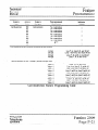
Marketing
Tnlllum
MacArthur
Costa
Mesa.
are
subject
Systems
92626,
Tel.:
(714)
WIllowdale,
Sales
Inc.
155 Gordon
Baker
Road,
Suite
206,
3N5
Tel.:
(416)
4940522
M2t-i
notxe.
International
Blvd..
California
w/fhout
Triltlum
Corporation
Canadian
Sales
Trrlllum Telephone
Ontario.
to change
Headquarte&U.S.Operations
Tetephone
1675
features
557-3300
Sales
Telephone
Systems
Inc.
603 March Road,
Telex: 053-4524,
P.O. Box 13030, Kanata. Onlarlo,
K2K 1X3
Tel.: (613) 592-2550.
Fax: (613) 592-2555
@ Copynghl
TRILLIUM
TM Trademark
91.0366-2A
F-3008-1
1987
of TRILLIUM
- March
1987
Telephm
Telephone
Printed
Systems
Systems
(I! Japan
Inc
Inc.
Technical
Service
Manual.,
Technical
Spe.cifications
_
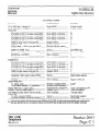
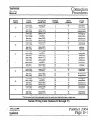
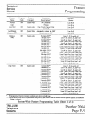
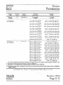
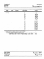
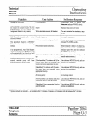
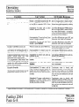
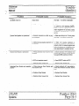
CONNECTORS
Equipment
JackslConnections
Cable Pairs
CO or PBX lines 1 through 10 ........................ .........
CO or PBX lines 11 through 20 ..............................
Master KSU:
CO 1 TO 10.. .................................................
STATIONS 10 TO i7 (to station wiring MDF) ....
STATIONS 18 TO 25 (to station wiring hlDF) ....
STATIONS 26 TO 33 (to station wiring MDF) ....
STATIONS 34 TO 41 (to station wiring MDF) ....
DOOR (to Door Answer Unit jack DA). ..............
POWER FAIL.. ........ I.. ...................................
PAGE (output - 200 mV rms into 600 Q) .........
MUSIC (music input - 50 mV rms). .................
SMDR (to SMDR Unit) ...................................
Connectors 1 and 2 (used to connect KSUs) ..........
EXTERNAL
BATTERY ...................... ..-...........
Ground ..........................................................
Expander KSU:
CO 11 TO 20 .................................................
STATIONS 42 TO 49 (to station wiring MDF) ....
STATIONS 50 TO 57 (to station wiring MDF) ....
’ STATIONS 58 TO 65 (to station wiring MDF)., ..
... STATIONS 66 TO 73 (to station wiring MDF) ... .
DOOR (to Door Answer Unit jack DA) ..;. ...... ......
POWER FAIL (to 1st PowerFail Transfer Unit) ...
Connectors 1 and 2 (used to connect KSUs) ..........
EXTERNAL
BATTERY ...................................
Ground ..........................................................
Station wiring MDF:
To station jacks.. .............................................
To dry contact interface (2 A, maximum). ............
Panther 2064 Sets (to station jacks). ..........................
DSS/BLF Units (to station jacks). ............................
Door Module (to Door Answer Unit Dl and D2). .........
SMDR Unit:
To KSU connector SMDR.. ..............................
To printer, terminal, or personal computer.. ..........
50-pin RJ2lC.I . . . . .. . . . . .. . .. . .. .. . . .
50-pin RJ21C . .. . . . .. . . . . .. . . .. .. .. . . .
25 (only 10 used)
25 (only 10 used)
50-pin RJ21C .. .. . . .. . . .. . . .. . .. .. . . .
50-pin RJ2lC to 66-block . .. ... .. .
50-pin RJ21C to 66-b&k . .. ... .. .
50-pin RJ21C to 66-block . .. ... .. .
50-pin RJ21C to 66-block . .. ... . ..
Modular RJ25C . .. .. . . .. . . .. . .. .. .. .. .
Special connector .. . .. . .. .. . .. .. . .. . ..
Mini-Jack l/8-inch, phono) ... .. .. .
Mini-Jack (l/8-inch, phono) . .. ... .
Special . . . .. . . . . . . .. . . . . . . . . .. . . . . . .. . . . . .
Special . . . .. . . . . . . .. . . . . . . .. .. . . . . . . . .. . . .
Molex connector . .. . .. . .. .. . .. . .. . .. . .
Screw terminal .. .. . .. . . .. . .. . . .. .. . .. .
25
25
25
25
25
3
Not used
1
1
(See SMDR Unit)
(See expander KSU)
1
Single 12 AWG wire
50-pin RJ21C .. .. . . .. . . .. . .. . .. . .. .. .
50-pin RJ21C to 66-block . .. ... .. .
50-pin RJ21C to 66-block...: .. .. .
50-pin RJ21C to 66-block . .. .. .. ..
5OSpin RJ2,lC to 66-block . .. .. .. .. ’
Modular RJ25C .. . .. . . .. . . .. . . .. . .. .. .
Special connector .. . .. . .. . .. .. .. . . .. . .
Special . . . .. . . . . . . .. . . . . . . .. .. . .. . .. . . . . . .
Special .. . . .. . . . . . . .. . . . . . . . . .. . . . . .. .. . . . .
Screw terminal . . .. . . .. . .. . .. . .. . . .. . .
25
25
25
$25
25
3
.
(See first Power Fail Transfer Unit)
Special (cables supplied)
1
Single 12 AWG wire
66-block to modular RJ14C.. .....
66-b&k to screw terminals.. .....
Modular RJ14C (or RJ25C**) ....
Modular RJ14C.. .....................
Screw terminals.. .....................
2 each*
1
2 each, cord supplied (or 3**)
2 each, cord supplied
1 for each module
Special.. .................................
DB-25.. ..................................
Special (cable supplied)
RS-232 cable
* Length of each station cable should not exceed 2000 feet of 24 AWG; all station runs are star (home run) configurations
** Sets may alternatively use a 6-conductor modular cord-to-RJ25C jack (to gain access to the Set’s speaker terminals)
TRILLIUM
Telephone
Systems
Panther 2064
Page C-l
Technical
Service
Matiuql
Technical
Specific.ations
: : i : :
: : : : : : : : : :
i
: : : : : : : : : : : : : : : : : : : : : : : : : : : : : : : : : : : : : : : : t
: : : : : : : : : : :
: : : : :
: : : : : : : : : : : : : : : :
: : : : :
i:
: : : : : : : : : : : : :
: : : : : : : : : : : : : : : : : : : : : : : : : : : : : : : : : : : : : : : : : : : : : : : : : : : : : : : : : : : : : : : : : : : : : : : : : : ~
.
.
.
.
.
.
.
.
.
.
.
.
.
.
.
.
.
.
.
.
.
.
.
.
.
.
.
.
.
.
.
.
.
.
.
.
.
.
.
.
.
.
.
.
.
.
.
.
.
.
.
.
.
.
.
.
.
.
.
.
.
.
.
.
.
.
.
.
.
.
.
.
.
.
.
.
.
.
.
.
.
.
.
.
.
.
.
.
.
.
.
.
.
.
.
.
.
.
.
.
.
.
.
.
.
.
.
.
.
.
.
.
.
.
.
.
.
.
.
.
.
.
.
.
.
.
.
.
.
.
.
.
.
.
.
.
.
.
.
.
.
.
.
.
.
.
. . . ”
.
.
.
.
.
.
.
.
.
; . . .
.
.
.
.
.
.
.
.
.
. .
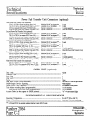
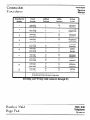
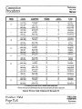
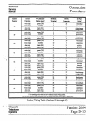
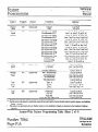
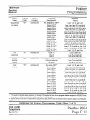
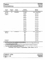
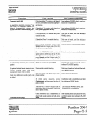
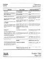
Power Fail Transfer Unit Connectors (optional)
First Power Fail Transfer Unit (optional):
C01.2 & C03.4 (from incoming lines l-4) .. ... .. ...
TK1.2 & TK3.4 (to master KSU lines 14) .. ... . ... .
CNJ (to expander KSU jack POWER FAIL) . ... .. ...
CNK (to 2nd Power Fail Transfer Unit jack CNJ)..
Second Power Fail Transfer Unit (optional):
C01.2 & C03.4 (from incoming lines 5-8) .. ... .. ...
TK1.2 & TK3.4 (to master KSU lines 5-8) ,.........
CNJ (to 1st Power Fail Transfer Unit. jack CNK)...
CNK (to 3rd Power Fail Transfer Unit jack CNJ)...
Third Power Fail Transfer Unit (optional):
C01.2 & C03.4 (from incoming lines 9-12) . .. ... ..
TK1.2 (to master KSU lines 9-10) ... .. . .. .. .. ... .. .. . ..
TK3.4 (to expander KSU lines 1l- 12) .. .. .. ... .. .. .. .. .
CNJ (to 2nd Power Fail Transfer Unit jack CNK)..
CNK (to 4th Power Fail Transfer Unit jack CNJ)..
Fourth Power Fail Transfer Unit (optional):
C01.2 & C03.4 (from incoming lines 13-16)......
TK1.2 & TK3.4 (to expander KSU lines 13-16)....
CNJ (to 3rd Power Fail Transfer jack CNK) .. ... .. ...
CNK (to 5th Power Fail Transfer Unit jack CNJ)..
Fifth Power Fail Transfer Unit (optional):
CO,l:2 & C03.4 (from incoming lmes 9 & lo)....
. TK1.2 ‘& TK3.4 (to expander KSU lines 17-2Oj...:
CNJ (to 4th Power Fail Transfer Unit jack CNK)..
Modular RJ14C to adapter***....
ModularRJ14C to adapter***....
Special connector . .. . .. . .. . .. .. . . .. .. .
Special connector . .. .. . .. . .. . .. . .. .. . .
2each
.
2each
1 (cable supplied)
(See 2nd Power Fail Transfer Unit)
Modular
Modular
Special
Special
RJ14C to adapter***....
RT14C to adapter***....
connector . .. .. . . .. . .. .. . .. .. . .
connector . .. . .. . .. .. . .. . .. .. . .
2each
2each
1 (cable supplied)
(See 3rd Power Fail Transfer Unit)
.Modular
Modular
Modular
Special
Special
IU14C to adapteir**....
2each
IU14C to adapter***....
2
RJ14C to adapter***....
2
connector . .. . .. . .. . .. .. . .. .. . . 1 (cable supplied)
connector . .. .. . . .. . .. .. . .. .. . . (See 4th Power Fail Transfer Unit)
Modular
Modular
Special
Special
RJ14C to adapter***....
RJ14C to adapter***....
connector . .. .. . . .. .. . .. . . .. .. .
connector . .. .. . . .. .. . .. . .. .. . .
Mod&r RJ14C to adapter+**....
ModaJar RJ14C toadapter’**....’
Special connector . .. . .. . .. . .. .l.......
2each
2each
1 (cable supplied)
(See 5th Power Fail Transfer Unit)
r.
2d
2each
1 (cable supplied)
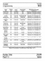
SMDR .UNIT (optional)
Data code.. ............................................................................................................
Character Bits ........................................................................................................
Start Bits ..............................................................................................................
Stop Bits.. ............................................................................................................
Parity ..................................................................................................................
Data rates (SMDR switch-selectable) .........................................................................
SMDR-Output
Device Signaling ..............................................................................
Output device (user supplied). ...................................................................................
Time before recording starts (programmable). ..............................................................
Grace period before timer starts (programmable). ....................................................
Account Codes (as they appear in SMDR printout) .......................................................
ENVIRONMENTAL
REQUIREMENTS
Operating Temperature.. ..........................................................................................
Relative Humidity ..................................................................................................
*** A 50-pin RJILlC-to-modular
Panther 2064
’ Page C-.2
ASCII
7
1
2
None
300,600, or 1200 bits per second
None required
8Ocharacter, serial printer
lto6lseconds
1 to 16 seconds
“A” + 4 user-entered digits
0 to 40 “C (32 to 104 “F)
Less than 90%. noncondensing
adapter that has 5 each RJ14C jacks
TRILLIUM
Telephone
Systems
[,
Technical
Service
Manual
Technical-
,
Specifications
.,......,....
..........::::::::::::::::::::::::::::::::::::::::::::::::~:::::::~:::::::::::::::::::::::::
:::::::
:::::::;:::::::::::
:::::::::::::::::
:,~
:::::::;
::::::::
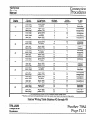
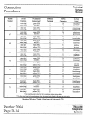
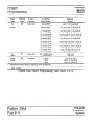
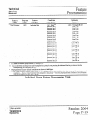
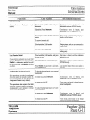
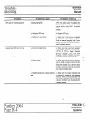
PO.WER REQUIREMENTS
Voltage . . .._.....................................................................................................,.....
Current . . . .. .. . . . . . . . . . . . . . . . . .. . . .. . . .. . .. . .. .. . . .. .. .. . . .. . . .l.....; . . . . . . . . . . . . . . , . . . . . . . . . . . . . . . . . . . . . . . . . . . . . . .‘...
STATION NUMBERING
PLAN
Panther 2064 Sets or OPX units . . .. . . .. . .. . . .. .. .. .. . . .. . .. . . .. . . .. . .. . .. . .. . . .. . . .. . .. . . .. . .. . . . .. . .. . . .. . .. .
DSS/BLF Units (in relation to associated/accompanying
115 V ac (k lo%), SO/60 Hz
1.8 A, maximnm load per KSU
Panther 2064 Set) . ... . ... .. .. .. ... .. .. .
10 through 73 (OPX unit not allowed on station 10)
Next higher station number
SYSTEM CAPABILITIES
CO or PBX Lines (each independently programmable for DTMF or pulse signaling) ...........
Intercom Speech Paths.. ........................................................
. .................................
OPX unit (optional - used with modem, answering machine, or remote sru.r&rd set) .........
Stations (including both non-handsfree or handsfree Sets and DSS/BLF Units or OPX units)
Non-handsfree or handsfree Sets.. ........................................................................
DSS/BLF Units ..............................................................................................
Speed call Numbers (up to 26 digits, pauses, or flashes each):
. .....................................................
Common (system-wide). .............................
Private ...........................................................................................................
Door Answer Unit (optional) ...................................................................................
Power Fail Transfer Units (optional). .........................................................................
t
18 or 19 with one or two Door Ansyer Units respedvely
?? 1st through 5th units transfer up to 4 incoming lines each: all knsferred
:
standard telephone setk(nqiPanther 2064 Sets)
TRILLIUM
Telephone
Systems
20t
4 per KSU
Up to 63
up to 64
up to 64
Up to 28
Up to 80
Up to 11 at each Set
2 (with 1 or 2 Door Modules each)
UP to 5tt
-_
lines are routedto pre-$sdld
’ *
I.
.
I
IB
Technical
Service
Manual
Connection
Procedures
:::::
STEP 1
INSTALLING THE KSUs
Site Preparation
System Uncrating
a
Because the KSUs are at the heart of the operation of the
Panther 2064 Electronic Key Telephone System, ensure that
its installation site meets the following criteria:
.
Clean, dry, and well ventilated (should meet the environmental requirements listed in Section C)
.
Within seven feet of the incoming CO, CENTREX,
or PBX line terminations
list.
h
If you are in area subject to power transients,
install a surge protector on the dedicated outlet.
Within five feet of ahedicated 110 V ac, 60 Hz, 3-’ wire grounded outlet - an outlet that is not on a
wall switch ,-
.
Not too distant from station terminations (the maximum distance to each station is 2000 feet, using 24
AWG wiring)
.
A 30” by 60” area of wall space should be reserved,
allowing room for Power Fail Transfer Units, the
SMDR unit, and the Door Answer Unit (whether
they are being installed now or might be in the
future)
Make sure that the customer’s feature requirements
have been documented on a Customer Feature
Selection Form.
Master KSU Installation
WARNING
.
Carefully unpack the System and confirm that all
ordered parts are present by checking them off
against the Customer’s order sheet and the packing
a
Mark the position of the 4 screw holes needed to
mount the master KSU on the backboard.
b.
Drive four screws (supplied) until their heads are
within l/&inch of the board’s surface.
c.
Using the four keyhole slots (narrow end up) in the
side flanges of the master KSU cabinet, hang the
unit on the four screws and tighten
them securely.
.
CAUTION
Failure to properly ground the master KSU
may void your Panther 2064 Electronic Key
Telephone System warranty.
d
Connect the ground lug at the top of the master
KSU to a cold water metal pipe or ground stake,
using copper wire that is 12 AWG or heavier (not
supplied).
Be sure that the cold water pipe’s metal continuity
is not broken by the use of plastic pipe.
Backboard Installation
If the KSU is to be mounted on a concrete or masonry wall,
a l/2-inch thick plywood backboard is recommended.
A ground stake should also meet the installation requirements of your local electrical code.
Depending on the wall’s construction and your method of installing the backboard, you might need screwdrivers
(various kinds and sizes), drills and bits (various sizes), # 10
masonry screws with plastic anchors (4 of each), or l/4:
screws with wall grip screw anchors (4 of each).
e
At the electrical service panel, equip the electrical
breaker for this outlet with a locking clip - or
mark it with a label to serve notice that this unit
,
should not be disconnected or shut off.
Mount the backboard at least 12 inches above the floor.
.
.
. .
. .
. .
. .
.
.
. .
. .
. . .
. . .
. . .
. . .
. .
. .
. .
. .
. . .
. . .
. .
. .
.
.
. .
. .
.
.
. .
. .
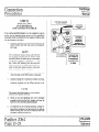
. .
. .
. .
. .
. .
. .
__,b .TRlLLlUM
Telephone
Systems
.
.
. .
. .
.
.
. .
. .
. .
. .
. . .
. . .
. .
. .
. . .
.. . .
. .
Y
.
.
. .
. .
. .
. .
.
.
. .
. .
. .
. .
.
.
. .
. .
. . .
. . .
. .
. .
. .
. .
. .
. .
:
.
. .
. .
.
.
. .
. .
. .
. .
. .
. .
.
.
. .
. .
.
.
. .
. .
. .
. .
. .
. .
..-.................................
. . . . . . . . . . . . . , .
. .
.
. .
. .
.
. .
. .
.
. . . . . . . . . . . . . . . . . . . . . . . . . . . ......’
..........................................................................
. .....................................................................................................................................................
.
.
:
...............................
I
Panther 2064
Page. D- 1
U
Technical
Service
Manual
Connection
Procedures’
Expander KSU Installation
a
b.
Fit the mounting bracket (supplied with the expander KSU) over the master KSU, aligning the top of
the mounting bracket with the top of the master
KSU.
Mount the expander KSU on the mounting bracket
using the 4 screws supplied with the expander
KSU.
CAUTION
Failure to properly ground the expander KSU
may void your Panther 2064 Electronic Key
Telephone System warranty.
.
c.
Connect the ground lug at the top of the expander
KSU to a cold water metal pipe or ground stake,
using ,copper wire that is 12 AWG or heavier (not
supplied).
$ ’ Be sure that the cold. water -pipe’s metal’continuit~
is not broken by the use of plastic pipe,
A ground stake should also meet the installation requirements of your local electrical code.
E
At the electrical service panel, equip the electrical
breaker for this outlet with a locking clip - or
mark it with a label to serve notice that this unit
should not be disconnected or shut off.
g
Install the two special cables supplied with the expander KSU between connectors 1 and 2 at the
bottom of the expander KSU and connectors 1 and
2 at the bottom of the master KSU.
STEP 2
CONNECTING
INCOMING TELEPHONE LINES
WARNING
Do not plug in the master and expander KSU
power cords until instructed to do so in Step 4.
NOTES
1. If the incoming telephone lines are not yet
installed, ask the telco that they be terminated
in two 50-pin RI21 connector, one for lines l10 and the other for lines 1 l-20.
2. If optional Power Fail Transfer Units are to
be installed, follow the instructionsin Step 12
to connect the incoming lines.
3. If one optional Door Answer Unit is to be
installed, line 10 must be left vacant; if a.second optional Door Answer Unit is to be
installed line.20 must be left vacant.
4. See also the Typical System
Diagrams on pages E- 1 and E-2.
Layout
Plug the 50-pin RI21 connector for lines l-10 into the 50pin connector on the right side of the master KSU labeled
CO 1 TO CO10 and the 50-pin RI21 connector for lines 1 l20 into the 50-pin connector on the right side of the expander KSU labeled CO1 1 TO CO20. Secure the KSU end of the
cables with the screws and plastic tie-wraps provided with
the units.
On the other hand, if the incoming lines are not terminated
in 50-pin RI21 connectors, wire them into two 66-blocks
(with female 25-pin connectors).
Then, install two 25-pair cable - with male 50-pin connectors at both ends - between the 66-blocks’s 50-pin
connector and the master and expander KSU 50-pin connectors, labeled CO 1 TO 10 and CO11 TO 20, respectively.
Secure the KSU end of the cables with the screws and plastic tiewraps provided with the units.
See the incoming line wiring table that starts on the facing
page for details.
. .
TRIL’LIUM
Telephone
Systems
Technical
Service
Manual
Connection
Procedures
Incoming Line
Number
Circuit
Function
66-Block
Terminal
SO-Pin
Connector
25 Pair
Cable*
1
voice (tip)
voice (ring)
1
2
26
1
white/blue
blue/white
2
voice (tip)
voice (ring)
3
4
27
2
white/orange
orange/white
3
voice (tip)
voice (ring)
5
6
28
3
white/green
green/white
4
voice (tip)
voice (ring)
7
8
29
4
white/brown
brown/white
5
voice (tip)
voice (ring)
9
10
30
5
white/slate
slate/white
‘6
voice (tip)
voice (ring)
11
12
31
6
red/blue
blue/red
7
voice (tip)
.voice (ring)
13
14;
32
‘7
red/orange
orange/red
8
voice (tip)
voice (ring)
15
16
33
8
red/green green/red
9
voice (tip)
voice (ring)
17
18
34
9
red/brown
brown/red
10
voice (tip)
voice (ring)
19
20
35 .
I
* .._
I
red/slate
slate/red
io
* The first color listed is the predominant color;
the second color listed is the track or stripe color.
Incoming Line Wiring Table (Lines 1 through ‘10)
-’
TRILLIUM
Telephone
Systems
Panther $064
Page D-3
Connection
Procedures
’
I
Technical
Service
Manual
Incoming Line
Number
Circuit
Function
66-Block
Terminal
50-Pin
Connector
25 Pair
Cable*
11
voice (tip)
voice (ring)
1
2
26
1
white/blue
blue/white
12
voice (tip)
voice (ring)
3
4
27
2
white/orange
orange/white
13
voice (tip)
voice (ring)
5
6
28
3
white/green
green/white
14
voice (tip)
voice (ring)
7
8
29
4
white/brown
brown/white
15
voice (tip)
voice (ring)
9
10
30
5
white/slate
slate/white
16
voice (tip)
voice (ring)
11
12
31
6
red/blue
blue/red
-17
voice (tip)
-. voice (ring)
13
14
18
voice (tip)
voice (ring)
15
16
33
8
red/green
green/red
19
voice (tip)
voice (ring)
17
18
34
9
red/brown
brown/red
- 20
voice (tip)
voice (ring)
19
20
35
10
red/slate
slate/red
.’
:
32
7.
‘,
red/orange
orange/red
* The first color listed is the predominant color,
the secondcolor listed is the tracer or stripe color.
Incomirig Line Wiring Table (Lines 11 through 20)
p&her
2()&J
‘.
..
.
‘.
TRliLlUM
Telephone
Systems
Page D-4
.................................................................................................................................................................................
................................................................................................................................................................................................................................................................................
. ..............................................................................................
.
........................................................................................................................................................................................_..........................................................................................................
............................................,
. . . . . . . . . . . . . . . . . . . . . . . . . . . . . . . . . . . . . . . . . . . . . . . . . . . . . . . . . . . . . . . . . . . . . . . . . . . . . . . . . . . . . . . . . . . . . . . . . . . . . . . . .
~~.------..-...................
I . .
. . . . . . . . . . . . . . . . . . . . . .
Technical
Service
Manual
Connection
Procedures
.........................,......................................_._.........::::::::::::::::::::::::::::::::::::::::::
..........................................................................................................................................................................................................................................................................................................................
:::::::::::::::::::::::::::::::::::
.*
. -.
[This page intentionally left blank]
.
.
. . . . . . . . . . . . .._......
.. .. .. . .. . .. . .
. . . . . . . . . . - . . . . . . . . . . . . . . . . . . . . . . . . . . . . . . . . . . . . . . . . . . . . . . . . . . . . . . . . . . . . . . . . . . . . . . . . . . . ..-a . . . . . . . . . . . . . . . . . . . . . . . . . . . . . . . . . . . . . . . . . . . . . . . . . . . . . . . . . . . . . . . . . . . . . . . . . . . . . . .......................
: _.........._..............
:: ..........._....._...........
.......
. . . . . . . . . . . . . . . . . . . . . . . . . . . . . . . . . . . . . . . . . . . . . . . . . . . . . . . . . . . . . . . . . . . . . . . . . . . . . . . . . . . . . . . . . . . . . . . . . . . . . . . . . . . . . . . . . . . . . . . . . . . . ......................
: .............................................
-
.TRILLIUM
Telephone
Systems
\
....................................
I.. ..............................................................................................................................
.....................................................................................................................................................................
Iy...........:
....................,
..........,
Panther 2064’
Page D-5
:::::::::::::::::::::::
v
:::::::::::::::::::::::::::::::::::::::::::::::::::::::::::::::::::::
::::::::::::::::
Technical
Connection
Service
Procedures
Manual
................................................:.:.....:..:
.........................................................................................................................................................
.................................................................................................................................................................................................................................................................
......
....,
STEP 3
INSTALLING STATION WIRING
a
NOTE
WARNING
To prevent damage to the KSUs while wiring,
make sure that the KSU power cords are not
plugged in. Do not apply power to the KSUs
until instructed to do so in Step 4.
Decide on the location and station number (from 10
up through 73) for each Set.
If an external amplifier is to be used at any of
the station locations, mount a 6-conductor
RI25 jack at the station location. See Step 13.
h
Mount a 4-conductor RI14 jack within 6 feet of the
desired Set location at each station.
1. Because much of the feature programming is
performed from station 10, choose a convenient or strategic location for station 10.
c.
On the backboard, mount four split 66-blocks with
a female 50-pin connector provided for each half
(left and right).
2. DSS/BLF Units require their own station
.wiring jack - and the station number of the
DSS/BLF Unit must be the next higher number
when compared to the station number of the
accompanying Set.
’
.
For example, if the Marketing Department’s
secretary was to be given a DSS/BLF unit, two
consecutively numbered station wiring jacks
- say station 62 and station 63 - would have
to be installed at the secretary’s desk.
d.
Install eight 25-pair cables - with male 50-pin
connectors at both ends - between the 66-block’s
50-pin connectors and the master KSU 50-pin connectors labeled STATIONS 10 TO 17.LOUD
BELL, 18 TO 25,26 TO 33, and 34 TO 41 and the
expander KSY 50-pin connectors
labeled
.STATIONS 42 TO 4950 TO 57,58 TO 65, and 66
TO 73.
NOTES
To continue the example, the secretary’s Set
would be connected to station 62 - and the
accompanying DSS/BLF Unit would be connected to station 63.
Panther .2064.
Page D-6
NOTE
See the table on the following eight pages for
wiring details for each group of eight stations.
Also, refer to the Typical System Layout
Diagrams on pages E-l and E-2.
e
For each station, install a length (not to exceed
2000 feet) of 4-conductor, 24 AWG cable from the
66-block terminals to the station wiring jack.
TRILLIUM
Telephone
Systems
.’
Technical
Service
Manual
Connection
Procedures
Station
Number
Circuit
Function
QConductor
Station Jackt
66-Block
Terminal
SO-F%l
Connector
25- Pair
Cable’
10
voice (tip)
voice (ring)
1
2
26
1
white/blue
blue/white
3
4
27
2
white/orange
orange/white
11
data b-&J)
voice (tip)
voice (ring)
green (GN)
red P>
black (BK)
yellow (YL)
5
6
28
3
white/green
green/white
7
8
29
4
white/brown
brown/white
12
data (tip)
data (fig)
voice (tip)
voice (ring)
green GN)
red (RD)
black (BK)
yellow (YL)
9
10
30
5
white/slate
slate/white
11
12
31
6
red/blue
blue/red
13
data (tip>
data b-i%)
voice (tip)
voice (ring)
green GN)
red VW
black@K)
yellow (YL)
green(GN)
rd(RD)
black(BK)
yellow W-1
&en (GN)
red cm.
black (EIK)
Yellow W-)
1.3
14.
32
7
red/orange
orange/red
data (tip)
. -.
:
data (tip)
data (ring)
14
voice (tip)
voice (ring)
15
data (tip)
data b-i%>
voice (tip)
voice (ring)
16
ha (tip)
data (fig)
voice (tip)
voice (ring)
17
data @PI
data b-4)
voice (tip)
voice. (ring)
data (tip>
data w%>
.I
,
13
I6
.
‘,
33
.8:*
.’
red/green
gef&&.
17’
’ 18
34
9
19
20
35
10
green WI
red CR-W
black (BK)
yellow W-1
21
22
36
11
23
24
37
12
black/orange
orange/black
green GN)
red WI
black @K)
yeflow WA
25
26
38
13
bl&/green
green/black
27
28
39
14
black/brown
brown/black
green (WI
=d@-W
black (BK)
yellow W-1
29
30
40
15
black/slate
slate/black
31
32
41
16
yellow/blue
blue/yellow
1’
red/brown
brown/red
lZd/Sht.f?
Slat&d
black/blue
. blue/black
t U&e matching color codes for the 4-conductor station wiring cables.
* The first color listed is the predominant color, the second color listed i+ the pacer or stripe color.
Station Wiring Table (Stations 10 through 17)
j TRILLIUM
- Telephone
Systems
‘Panther.2064
Page D-7
Connection
Procedures
Station
Number
18
Circuit
Function
CConductor
Station Jacki
66-Block
Terminal
50-Pin
Connector
25 Pair
Cable*
voice (tip)
voice (ring)
.green (WI
red (RD>
black (BK)
yellow (YL)
1
2
26
1
white/blue
blue/white
3
4
21
2
white/orange
orange/white
green WI
red W>
black (BK)
yellow (YL)
5
6
28
3
white/green
green/white
7
8
29
4
white/brown
brown/white
9
10
30
5
white/slate
slate/white
dm (tip>
data (ring)
green (WI
red (RD)
black (BK)
yellow (YL)
31
6
red/blue
blue/red
voice (tip)
voice (ring)
green WI
red (RD)
13
14
32
7
red/orange
orange/red
black (BK)
yellovv (YL)
15
16
33
8.
red/green
.‘. ‘gr&&d
green GW
red (RD)
black (BK)
yellow (YL)
17
18
34
9
reillbrown
brown/red
19
20
35
10
red/slate
slate/red
green (WI
red (RD)
black (BK)
yellow (YL)
21
22
36
11
black/blue
blue/black
23
24
37
12
black/orange
orange/black
green GW
red (RD>
black (BK)
yellow (YL)
25
26
38
13
black/green
green/black
27
28
39
14
black/brown
brown/black
green (0
red CRD)
black (BK)
yellow (YL)
29
30
4o
15
black/slate
slate/black
31
32
41
16
yellow/blue
blue/yellow
data (tip)
data b-hi9
voice (tip)
voice (ring)
19
.
Technical
Service
Manual
data (tip)
data b-hi9
voice (tip)
voice (ring)
20
21
data (tip)
daf” (ring)
_
voice (tip)
voice (ring)
22
data (tip)
data (ring)
23
voice (tip)
voice (ring)
24
data (tip)
data b-w
voice (tip)
voice (ring)
data (tip)
data (ring)
voice (tip)
voice (ring)
25
data (tip)
data (ring)
11
12
I
,
t Use matching color codes for the 4-conductor station wiring cables.
* The first color listed is the predominant color; the second color listed e the tracer or stripe color.
Station Wiring Table (Stations 18 through 25)
.
. . . . . . . . . . . . . . . . . . . . . . . . . . . . . . . . . . . . . . . . . . . . x.;
. . . . . . . . . . . . . . . . . . . . . ... . . . . . . . . . . ... . . . . . . . .
::::;:::::y::::
y.p:y
” P&tither 2064
Page D-8 ’
*:::::::::::::::::
:‘.:::y::;::::
:‘.::::
::*y.;
::::::y:::
ye::’
.::::::
:‘/::
T*yy
*::::::::::::::::
:‘.:::::::::
:::::::::::::::
::::::::::
:: ::::::::::::::::::::
i:
::::::
:::-;:
:‘.:::::::::::::::::::::::::
TRILLIUM
Telephone
Systems
-’
Technical
Service
Manual
Connection
Procedures
Station
Number
Circuit
Function
CConductor
Station Jack?
66-Block
Terminal
SO-Pin
Connector
25- Pair
Cable*
26
voice (tip)
voice (ring)
1
2
26
1
white/blue
blue/white
3
4
27
2
white/orange
orange/white
27
data (tip)
data b-%)
voice (tip)
voice (ring)
green GW
red CRD)
black (BK)
yellow (YL)
5
6
28
3
white/green
green/white
7
8
29
4
white/brown
brown/white
28
data (tip>
data b-h3>
voice (tip)
voice (ring)
green GN)
red W>
black (BK)
yellow (YL)
green (WI
red P-W
black @T()
yellow (YLJ
9
10
30
5
white/slate
slate/white
11
12
31
6
red/blue
blue/red
green(GN)
r&p)
black (BK)
yeliow (YL)
13
.14
15
16,
32
7
red/orange
~~ge/red
33.
Wgreen
;gree$&
29
data (tip)
data b-w
voice (tip)
voice (ring)
data (tip)
data(ring)
-.
30
voice. (tip)
voice (ring)
31
data (tip)
data (l-Q>
voice (tip)
voice (ring)
32
data (tip)
data ww)
voice (tip)
voice (ring)
33
data (bP>
data wx)
voice (tip)
voice (ring)
data (tip)
data b-&z>
.’
.
-: 9
.&
17
18
34
9
red/brown
brown/red
19
20
35
10
l-d/Slate
SlZlt&Xl
green GN)
red CRD)
21
22
36
II.
black/blue
blue/black
bh& (BK)
yellow 0
23
24
37
12
black/orange
orange/black
green (0
d(RD),
black (BK)
Wow WI
25
26
38
13
black/green
green/black
27
28
39
14
black/brown
brown/black
green GN)
reti (RD)
black (BK)
Wow WA
29
30
40
15
black/slate
slate/black
31
32
41
16
yellow/blue
blue/yellow
green(W
rd(RD)*
black (BK)
yellow (YL)
’
t Use matching color codes for the 4-conductrx station wiring cables.
* The fmt color listed is the predo minant color, the second color- listed is .the tracer or stripe colors
Station Wiring Table (Stations 26 through 33)
_.:
TRILLIUM
Telephone
Systems
.
Pitithef 2064
Page D-9
Connection
Procedures
Station
Technical
Service
Manual
Circuit
Function
CConductor
Station Jack?
66-Block
Terminal
50-Pin
Connector
25- Pair
34
voice (tip)
voice (ring)
1
2
26
1
white/blue
blue/white
3
4
27
2
white/orange
orange/white
35
data (tip)
clata b-w
voice (tip)
voice (ring)
green 00
red 0)
black (BK)
yellow (YL)
5
6
28
3
white/green
green/white
data (ring)
green (GN)
red @W
black (BK)
yellow (YL)
7
8
29
4
white/brown
brown/white
voice (tip)
voice (ring)
green (0
red (RD)
9
10
30
5
white/slate
slate/white
data (tip)
data (ring)
black (BK)
yellow (YL)
11
12
31
6
red/blue
blue/red
37
voice (tip)
voice (ring)
13
14
32
7
red/orange
orange/red
15
.‘, + : .-16..
33
8
red/green
green/red
38
data (tip)
*b b-hi9
voice (tip)
voice (ring)
green (0
red W>
black, (BK)
yellow-(YL)
green GN)
red (RD)
17
18
34
9
r&browh
brown/red
black (BK)
yellow (YL)
19
20
35
10
red/slate
slate/red
green VW
red VW
black (BK)
yellow (YL)
21
22
36
11
black/blue
blue/black
23
24
37
12
black/orange
orange/black
green GN)
red (RD)
black (BK)
yellow (YL)
25
26
38
13
black/green
green/black
27
28
39
14
black/brown
brown/black
green VW
red CRD)
black (BK)
yellow (YL)
29
30
40
15
black/slate
slate/black
31
32
41
16
yellow/blue
blue/yellow
Number
data WP>
36
data (tip)
data (ring)
39
voice (tip)
voice (ring)
40
data (up)
data b-&d
voice (tip)
voice (ring)
data (tip)
data (ring)
41
voice (tip)
voice (ring)
data (tip)
data 0-w
.
.
I
.
.
.
Cable*
t Use matching color codes for the 4-conductor station w+ing cables.
* The first color listed is t&e predominant color; the second color listed is the tracer or stxipe color.
Station Wiring Table (Stations 34 through 41)
.
Panther 2064
Page D-10
‘.
TRI’LLIUM
Telephone
Systems
Technical
Service.
Manual
Connection
Procedures
.
Station
Number
Circuit
Function
CConductor
Station Jackt
66-Block
Terminal
SO-Pill
Connector
25- Pair
Cable*
42
voice (tip)
voice (ring)
1
2
26
1
white/blue
blue/white
3
4
27
2
white/orange
orange/white
43
data (tip)
data 0-e)
voice (tip)
voice (ring)
green (W
red W)
black (BK)
yellow (YL)
5
6
28
3
white/green
green/white
7
8
29
4
white/brown
browu/white
44
data (up)
data b-b9
voice (tip)
voice (ring)
green (0
=d(RD)
black (BK)
yellow (YL)
green WI
red WI
black(BK)‘
yellow (YL)
9
10
30
5
white/slate
slate/white
11
12
.31
6
red/blue
blue/red
green (0
red (RD)
black (BK)
: ’ yebow’
13
14
32
-7
red/Or;mge
o=wzw.
15
‘; 16 -
33
8
17
18
34
9
19
20
35
10
red/slate
21
22
36
11
black/blue
blue/black
23
24
37
12
black/orange
orange/black
green(GN)
fit-W
black (BK)
yellow (YL)
25
26.
38
13
27
28
39
14
black/green
green/black
black5rown
brown/black
green GN)
=-dcRD)
black (BK)
Yellow Co
29
30
40
15
black/slate
slate/black
31
32
41
16
yellow/blue
blue/yellow
‘.
data (up)
data NW>
voice (tip)
voice (ring)
45
data (tip)
.&ita (rink).
46
’
,
voice (tip)
voice (ring)
47
ma (tip)
data 6-w
voice (tip)
voice (ring)
48
data (tip)
data W-G)
voice (tip)
voice (ring)
49
data (tip)
data mvs)
voice (tip)
voice (ring)
data (up)
data w-43)
green K-W
red W>
black (BK)
yellow (YL)
green GN)
=d(RD)
black (BK)
Now W-1
red/green
‘greenfred’
:
(
red/brown
brown/red
Shte/Ed
t Use matching color codes for the 4-conductor station wiring cables.
* The fmt c&r listed is the predemimnt color, the secondcolor listed is the.uacer or stripe color.
Station Wiring Table (Stations 42 through 49)
.
.....
“I.,
y..
....................
.........
..”
i..
.................................................................................................
.........................................................................................................................................................
TRILLIUM
Telephone
Systems..
.
.
. .........
. ................................
.....................................................
> ...............................................................................
. ....................
i ........................
” ..................
Panther 2064
Page D-l 1
Connection
Procedures
Station
Number
Technical
Service
Manual
Circuit
Function
4-Conductor
Station Jack?
66-Block
Terminal
50-Pin
Connector
25- Pair
Cable*
voice (tip)
voice (ring)
green GN)
red WI
1
2
26
1
white/blue
blue/white
data (tip)
data (l-e)
black (BK)
yellow (YL)
3
4
27
2
white/orange
orange/white
voice (tip)
voice (ring)
green WI
red OW
5
6
28
3
white/green
green/white
data (tip)
data bx>
black (BK)
yellow (YL)
7
8
29
4
white/brown
browdwhite
voice (tip)
voice (ring)
greenWI
red (RD>
10
5
white/slate
slate/white
data (tip)
data (e=T>
black (BK)
yellow (YL)
11
12
31
6
red/blue
blue/red
voice (tip)
voice (ring)
13
14
32
7
red/orange
orange/red
data (tip).
data (ring)~
green(GN)
rf2.d(RD>
black (BK)
.yelkW (YL)..
15
16.
33
.8’
~edlg-reen
greetid,
voice (tip)
voice (ring)
green VW
red 0)
17
18
34.
9
data (tip)
aa b-a9
voice (tip)
voice (ring)
black (BK)
yellow (YL)
19
20
35
10
green(GN)
red(RD)
21
22
36
11
black/blue
blue/black,
data @PI
data 6-h)
black (BK)
yellow (YL)
23
24
37
12
black/orange
orange/black
voice (tip)
voice (ring)
green GN)
red (RD)
25’
26
38
13
black/green
green/black
data (tip)
data w%)
black (BK)
yellow (YL)
27
28
39
14
black/brown
brown/black
voice (tip)
voice (ring)
green GN)
red (RD)
29
30
40
15
black/slate
slate/black
data (tip)
data (l-i%)
black (BK)
yellow (YL)
31
32
41
16
yellow/blue
blue/yellow
I
50
51
I
52
53
.
54’
55
56
57
‘,
t Use matching color codes for the 4cpnductor station wiring cables.
* The frost color listed is the predominant color; the second color liited is the tracer or stir
.
red/brown
brown/red
IWifSlate
slate/red
color.
Station Wiring Table (Stations 50 through 57)
:::;::::-:::::::
::
::::::::-:::::::
:”
.
.
. .
. .
. . .
. . .
. .
. .
.
.
. .
, .
. .
. .
. .
. .
. . .
. . .
. .
. .
.
.
. .
. .
.
.
. .
. .
. . .
. . .
. .
. .
. .
. .
.
.
. .
. .
. .
. .
.
.
. .
. .
.
.
. .
. .
. . .
. . .
. .
. .
. .
. .
.
.
. .
. .
.
.
. .
. .
. .
. .
. .
. .
. . .
. . *
. .
. .
.
.
. .
. .
. . .
. . .
. .
. .
. .
. .
. . .
. . .
. .
. .
. . .
. . .
. .
. .
. .
. .
.
.
. .
. .
.
.
. .
. .
. .
. .
. . .
. . .
. .
. .
. .
. .
. . .
. . .
. .
. .
. .
. .
. .
. .
.
.
. .
. .
. .
. .
. . .
. . .
. ....................................................................................-...........
. . . ..................................................~..............................................................
_
...._...........
I
Pa&her 2064
Page D-12
‘.
TRILLIUM
Telephone
Systems
Connection
.Procedures
Technical
Service
Manual
Circuit
Function
4-Conductor
Station Jack?
66-Block
Terminal
50-PiIi
Connector
25- Pair
Cable+
58
voice (tip)
voice (ring)
1
2
26
1
white/blue
blue/white
3
4
27
2
white/orange
orange/white
59
ha (tip)
data @v3>
voice (tip)
voice (ring)
green WI
=d(RD)
black (EN)
yellow OW
5
6
28
3
7
8
29
4
white/green
green/white
white/brown
brown/white
60
data (tip)
data (mo
voice (tip)
voice (ring)
green GN)
&t-W
black (BK)
yellow (YL)
green GW
=d(RD)
black(BK)
yellow (YL)
9
10
30
5
whiteMate
slate/white
Ii
. 12
31
6
red/blue
blue&d
32
7
red/orange
orange/red
Station
Number
61
data @PI
Clara@%9
voice (tip)
voice (ring)
62
data (tip)
data(ring)
.
voice (tip) voice (ring)
63
data (tip)
dara (ai9
voice (tip)
voice (ring)
64
data (tip>
data (fig)
voice (tip)
voice (ring)
65
data (tip>
tkQa 6-a)
voice (tip)
voice (ring)
data (tip)
Clarab%>
_I
13
14’
green (0
=dW)
black(BK)
yellow cn;)
15
lf;
.
17
518
33
81%
34
9
19
20
35
10
red/Slate
Sli3t.&Td
green (GN)
d(RD)
black (BK)
Wow 0
21
22
36
11
black/blue
- blue/black
23
24
37
i2
bkdorringe
orange/black
green (WI
d(RD)
blztck(EX)
yellow WI
25
26
38
13
blackjgreen
grchblack
27
28
39
14
black/brown
brown/black
mn GN)
d(RD)
29
30
40
15
black/slate
slate/black
black (BQ
Yellow WI
31
32
41
16
yellow/blue
blue/yellow
-green(GN)
=d(RD)
black (BK)
Wow VJ4
t Use matching color
codes
* The first color listed is the predominant
’
*
’
for the 4-conductor station wiring cables.
color; the second color listed is the tracer or.stipe
.’
_
.red/green
.’ greeti
‘,
red/brown‘
brown/red
color.
Station Wiring Table (Stations 58 through 65)
<(‘
-;
:=::“-“::=::“::::::::::::::::~:::::::::::::::.~:::::::::::::::::::::::::::::::::::::::::::::::::::~~:::::::::::::::::::::::::::::::::::::::::::::::::::::::::~::::::::::.~:::::::::::::::::::::::::~:::::::~:::::::::~::::::::::::::::::~
TRILLIUM
Telephone
Systems
Panther 2064 Page D-13
Technical
Connection
Service
Procedures
Manual
.............................................................................................................................................................................................................................................._........................___.
,.........................................
__..._...I
....”.-...
_...............................................................................................................................................................................
station
Number
Circuit
Function
voice (tip)
voice (ring)
CConductor
Station Jackt
66-Block
Terminal
SO-Pin
Connector
25- Pair
1
2
26
1
white/blue
blue/white
27
2
white/orange
orange/white
Cable*
data @w>
gr=n GN)
red NY
black (BK)
yellow (YTJ
67
voice (tip)
voice (ring)
green GN)
red WJ>
28
3
white/green
green/white
black (BK)
yellow (YL)
29
4
white/brown
brown/white
68
data (tip)
data 6-a)
voice (tip)
voice (ring)
9
10
30
5
white/slate
slate/white
11
12
31
6
red/blue
blue/red
13
14
15
.16
32
7
red/orange
orange/red
66
I
data @PI
data (tip)
data b-49
voice (tip)
voice (ring)
69
71
73
green (W
red (RD)
data (tip)
data b-h9
voice(tip)
voice (ring)
black (BK)
yellow’ (YL)
data WP>
data 6-w
voice (tip)
voice (ring)
17
18
34
9
red/green
green/red
red/brown
brown/red
black (BK)
yellow (YL)
19
20
35
10
red/slate
slate/red
green GN)
red W>
21
22
36
11
black/blue
blue/black
data(l-i%)
black (BK)
yellow (YL,)
23
24
37
12
black/orange
orange/black
voice (tip)
voice (ring)
green KW
-red (RD)
25
26
38
13
black/green
green/black
data (tip)
datab%)
black (BK)
yellow (YL)
27
28
39
14
black/brown
brown/black
voice (tip)
voice (ring)
-red (I&)-
29
30
40
15
black/slate
slate/black
data (tip)
data ww)
black (BK)
yellow (YL)
31
32
41
16
yellow/blue
blue/yellow
data (tip)
72
green (0
red W>
black (BK)
yellow (YL)
green (GN)
red CRD)
’
’
men (GN)
,>
,.‘s’
..:
.
s
t Use matching color codes for the 4conductor station wiring cables.
* The first color listed is the predominant color; the second color listed is the tracer or stripe color.
Station Wiring Table (Stations 66 through 73)
.
panther
2064
Page D-14
.’
_
.:
‘.
TRlLLlUfvl
Telephone
Systems
.
Technical
Service
Manual
Connection
Procedum
.
___
.. ....... .... .. . .. .. .
. .
.
. . .
. .
,.....................................,........................................
;’......................................................................................~...........................................................
(....,.,..,,,,,,~~~~~,,~~,,,,,~~,,~,.~.
I
i
Lift the handset and press the line 2 key: dis; :onc’
is heard; if your Set has an accompanyin_r T)SS/
BLF Unit, the station indicators for your Set zz.i for
your DSS/BLF Unit go ON; the intercom itiicator goes OFF; and the lint 2 indicator \\‘!SKS
slowly.
j.
Hang up the handset: dial tone is rcmovcd: 3r.J all
indicators go OFF.
2.If the SMDR unit is to be install&, it should
be installed prior to conducting these tests. See
step 11.
k
Repcat steps i and i for lines 1 and 3 through 10 including lines 10 and 20, if not used for the Door
Answer Units.
Connect the KSU power cords to the surge protcc. tor previously installed at the 110 V ac power
outlet: the recessed indicator on the master KSU
goes ON (with a slight flicker) indicating that the
system is opcrativc.
I.
Rcpcat
STEP 4 ’
CONDUCTING
THE INITIAL
SYSTEM AND STATION TESTS.
,’
NOTES
1. If the indications described below do not
occur, refer to the Troubleshooting section.
it
b.
Set BATTERY to ON on the master KSU (if ncccssary, use a paper clip or other pointed object such
as a pen or pencil to set KSU miniature DIP
switches).
c . Set-I PROGRAM to ON
. on the mfistcr KSU.
,
d.. Push the rcccsscd RESET pushbutton once on the
master KSU: in about 1 second, the rcccsscd indicator on the master KSU starts to flicker.
.c
f.
g.
h.
Set PROGRAM to OFF on the master KSU.
Push the rcccsscd RESET pushbutton again: the
system is now set the factory prcprogrammcd conditions (for dctiils on what those coriditions arc, see
the Fcaturc Programming section).
At station 10, plug in the 4-conductor modular cord
supplied with the Set bctwccn the Set and the staLion wiring jack.
Press the Set’s Intercom
key: the Set’s spcakcr
emits a continuous tone and the Intercom indicator
goes ON.
TRILLIUM
Telephone
Systems
steps
s through k for the remaining stzdons.
Unless you have optional items to install (the Door .\nswcr
Unit, the OPX unit, the SMDR unit, the Power Fail Tr.lnsfcr
Unit, external paging cquipmcnt, a loud bell, or a music
source), your Panther 2064 Electronic Key Tclcrhonc
System is now ready for programming or operation.
STEP 5
CONNECTING
.THE BACKUP BATTERIES,
Each KSU has a white plastic Mo’lcx connector at its top for ..
connecting irs 01vn cxtcrnal backup battery. The backup battcrics used (such ‘as the TRI 23/2.5B from Alpha
Tcchnologics). should provide 24 V dc at 2 Amps for an CX-,
tcndcd pcri& of time.
a
Connect the positive (+) terminal of each b:utcry
(usually the red lcad) to the left side of the‘ corrcsponding KSU connector.
b.
Connect the ncgativc (-) terminal of each tr:lttcry
(usually the black Icad) to the right side of the corresponding KSU connector.
Once conncctcd, switchovcr to the backup battcrics occurs
automatically when power fails.
Panther 2064
Page D-15
........
................................___
........_...:::::::::::::....-I.........
.....................................................................................................................................................................................................................................................................,................................................................................................................................................................................
Technical
Connection
Service
Procedures
Manual
.......................................................................:....................................................................................................
i.......___..__..................................”
..__,.__......_._..,..........
_...,,._._..
...............................................................r...................................................................................
r...,......................,.....................!..........................
:..............................
STEP6 ’
CONNtiCTING
DOOR ANSWER UNIT
AND DOOR MODULES
NOTE
If you have chosen to install one Door Answer
Unit with its one or two Door Modules, line 10
must be left vacant: If you have chosen to install a second Door Answer Unit with its one
or two Door Modules, line 20 must also be left
vacant
Door Module Installation
a
Disassemble each Door Module (separate the front
from the back) by removing the screw securing the
cover.
h
Mount the backs of all the Door Modules to be
used at the desired entryway locations, using the
two mounting screws furnished with each Door
Module.
C.
Run a length (not to exceed 2000 feet) of 2conductor, 24 AWG wire from the first Door
Answer Unit to two Door Modules - and from the
second Door Answer Unit to the remaining two
Door Modules.
d
Feed the wire through the hole in the base of the
back of each Door Module.
e
Strip the cable end and secure it to the screw terminals found on the backside of the Door Module’s
front assembly.
f.
Replace the Door Module’s cover and tighten the
screw
the front to the back,
8 to secure
,
g.
At each Door Answering Unit, strip the cable ends
and secure the cable from Door Module 1 to the
screw terminals labeled Dl and the cable from
Door Module 2 to the screw terminals labeled D2.
Door Answer Unit Installation
a
Mount the first Door Answer Unit on the backboard along with the KSU, using the four screws
supplied with the equipment.
b.
Connect the 6-conductor modular cord (not supplied) to the connector labeled DOOR on the
master KSU and the connector labeled DA on the
first Door Answer Unit.
c
&Iount the second Door’ Answer Unit on the backboard along with the .KSU, using the‘fourscrews
supplied with the equipment.
d
Connect the 6-conductor modular cord (not supplied) to the connector labeled DOOR on the
expander KSU and the connector labeled DA on the
second Door Answer Unit.
.-
........................................................,......................................................................
..............................:::::::::::::::::::::::::::::::::::::::::::::::::::::::::::::::::
........................*......**
::::::::::::::::::::::::::::::::::::::::::::::::::::
Panther 2064
Page D-16
TRILLIUM ‘<
Telephone
Systems
. ..
. .
. .. .
. .
.
. ..
.
. .
.. ..
..
. ..
.. . . .. ..
.
. .
.
. .
. ..
. .
.. ..
. ..
.. .
.. .
.
. .
. ..
..
.
: 1..
.
. .
. .
. .
.
.
. .
. .
. .
. .
.
.
. .
.
. .
.
. .
. .
. .
.
. .
. .
. .
.
.
. .
.
. .
.
. .
. .
.
. .
.
.
.
. .
.
.
. .
. . . .
. .
. .
.
.
. .
.
. .
.
. .
.
. .
. .
. .
.
. .
. .
.
.
.
. .
.
. .
.
. .
. .
.
.
. .
. .
. .
.
.
. .
.
. .
.
. .
. .
. . .
. .
. .
. .
. .
.
. . .
. . . .
. .
. .
.
. .
.
. .
.
. .
.
.
. .
.
.
. . . .
. .
........................................................................
.
.
.
. .
. .
.
.
.
.
.
.
.
:::i:;::
I
............
;.,;,
Connection
Procedures
Technical
Service
Manual
Door Answer Unit Test
C.
NOTE
Door Module 2-initiated calling:
i
At Door Module 2’s entryway, have someone
press the door button: four groups of 2 long
tones are heard at all Sets programmed to ring
on line 10; and the line 10 indicator FLASHES
slowly.
ii.
At any Set, pick up the handset and press the
line 10 or 20 key: the line IO or 20 indicator
WINKS: if yours is a BLF Set, your station indicator goes ON: and you and the person at the
entryway are connected.
iii
At the Set, hang up the handset: all indicators
go OFF; and the call is terminated.
If the indications described below do not
occur, rcfcr to the Troubleshooting section.
a
. .
Door Module l-initiated calling:
i.
ii.
At Door Module l’s entryway, have someone
press the door button: four groups of 4 short
tones arc heard at all Sets programmed to ring
on line 10 (or lint 20, for the second Door
Answer Unit); and the line 10 or 20 indicator
FLASHES slowly.
At any Set, pick up the handset and press the
line 10 or 20 key: the ,linc 10 .or 20 indicator
WINKS; if yours is a BLF Set, your station indicator goes ON; and you and the person at the’
entryway arc conncctcd.
iii. At the Set, hang up the handset: all indicators
.
_ ‘go OFF; and the call is tcrm$atcdY .
‘b.
Set-initiated calling:
NOTE
Set-initiated door module intercom calls can
only bc placed to Door Module 1, not to Door
Module 2.
i.
Altemativcly, at any Set, pick up the handset
and press the line 10 key: the line 10 indicator
WINKS; if yours is a BLF Set, your station indicator goes ON; and the person at Door
Module 1 hears a burst of ringing.
ii.
At the entry way whcrc Door Module 1 is installed, the person responds by speaking in the
direction of the Door Module: you and the pcrson at the entryway arc conncctcd.
iii. At the Set, hang up the handset: all indicators
go OFF; and the call is terminated.
.
“.
TRILLIUM
Telephone
Systems
’
:
_
.,
:
‘.
’ panther
..2064
Page D-17
..
Technical
Connection
Service
Manual
Procedures
,...
........................._......__...
. ..........,........,.....................................:....... . ...,.................................................................................,............................,................................_...
........................................
*.........
*..,.........,...........................,.................................
:.,,.
.........................................*......I............ .............................................*..*
STEP 7
CONNECTING
THE MUSIC SOURCE
Music Connection
a
Connect one end of the cable (not supplied) into the
music source’s output jack.
b.
Connect the other end, which terminates in a l/8inch mini-jack (phono, not stereo or attenuator),
into the KSU connector labeled MUSIC.
c
Testing the background music on hold:
i
Have someone call in on outside line 1 (alternatively, you can call line 1 from line 2):
ringing is heard at all stations programmed to
ring on line 1; and the line 1 indicator
FLASHES slowly.
ii.
At any station, pick up the handset and press
the line 1 key: the line 1 indicator WINKS
slowly: if yours is a BLF Set, your station indicator goes ON; and a connection is made with
the outside caller.
Music Test
NOTE
iii. After informing the outside caller of your intentions, press the Hold key and hang up the
handset: the line 1 indicator FLASHES quickly; if yours is a BLF Set, your station indicator
goes OFF; and the outside caller hears the
background music.
If the indications described below do not
occur, refer to the Troubleshooting section.
a
Turning background music on at a Set:
i.
5’
At any station, with the handset in ‘its cradle,
press the lnt~rcom Key: the Intetqin
indicator WINKS slowly; and a. continuous tone is
heard over the Set’s speaker.
ii.
With the handset still in its cradle, dial * 4: the
Intercom indicator goes OFF; and the continuous tone is replaced by background music
coming from the Set’s speaker.
iii
At the music source, adjust the level of the
background music for the desired loudness.
-
iv. After a few seconds, retrieve the calI by pick” ing up the handset and $ressing the line l-key:
the line 1 indicator WINKS slowly; if yours is
a BLF Set, your station indicator goes 0N;the
outside caller no longer hears the background
music; and the connection with the outside
caller is restored.
v.
b.
Turning background music off at a Set:
i
At any station, with the handset in its cradle
press the Intercom Key: the Intercom indicator WINKS slowly; and a continuous tone is
heard over the Set’s speaker.
ii.
With the handset still in its cradle, dial * 4: the
Intercom indicator goes OFF; and neither the
continuous tone nor the background music is
heard over the Set’s
- speaker.
Confirm the success of the background music
on hold test with the outside caller.
vi. Hang up the handset: all indicators go OFF,
and the call is terminated
TRILLIUM
Telephone
Systems
Connection
Procedures
Technical
Service
Manual
\
STEP8
”
CONNECTING
THE EXTERNAL
PAGING EQUIPMENT
Equipment Connection
.
a
Connect one end of the cable (not supplied) into the
external paging equipment’s input jack.
b.
Connect the other end, which terminates in a l/8inch mini-jack (phono, not stereo or attenuator),
into the KSU connector labeled PAGE.
,
1
Paging Test
’
NOTE
If the indications deicribed below do not.
occur, i&fer to the Troubleshooting section.
a
At any station, pick up the handset and press the
Intercom Key: the InterCOm
indicator WINKS
slowly; if your Set has an accompanying DSS/BLF
Unit, the station indicators for your Set and for your
DSS/BLF Unit go ON; and a continuous tone is
heard.
b.
Dial 99: a double tone burst is heard over the extcrnal paging loudspeaker.
c
Make a test announcement: Ihe test announcement
is heard over the external paging loudspeaker.
d.
Hang up the handset: all indicators go OFF; and the
external paging loudspeaker falls silent.
I
,
TRILLIUM
Telephone
Systems
Panther 2064
Page D-19
...________......__.................................~.
Technical
Service
Manual
Connection
Pr0cedure.s
. . . . . . . . . . . .._.............................
,...........................................................
, . . . . . . . . . . . . . . . :. . . .._........._.........................................................................................................................
: .. .. . .. . .. .. . .. .. . .. . ... .. . . .. .. . .. .. .. .. . .. . .. .. .. .. .. . . ... . .. . ... .. . .. ..
: . . . . . . . . . . . . . . . . . . . . . . . . . . . . . . . . . . . . . . . . . . . . . . . . . . . . . . . . . . . ‘ . . . . . . . . . . . . . . . . . . . . . . . . . . . . . . . . . . . . . . . . . . . . . . . . . . . . . . . . . . . . . . . . . . ..-.................................................................................
. -
STEP 9
CONNECTING
,AN EXTERNAL LOUD BELL
Equipment Connection
Loud Bell Test
.
NOTES
1. If the indications described below do not
occur, refer to the Troubleshooting section;
Connect a 2-conductor cable between terminals 49 and 50 of
the 66-block (the violet/slate pair in the 25pair cable that
connects the master KSU conneetor labeled STATIONS 10
TO 17.LOUD BELL to the (X-block) and an external dry
contact interface unit, such as the Wheeloch model 24-24
(not supplied). Connect an external loud bell or other sounding device to the dry contact interface unit.
Panther 2064
Page D-20
!
*
2. The factory preprogrammed condition for
the loud bell is both day and night bell. If you
are installing a new system, the loud bell
should ring on all incoming calls.
3. See Feature Programming for details on how
to program the loud bell.
a
Have someone call in on outside line 1: the line 1
indicator FLASHES slowly: and the external loud
bell rings.
b.
At any station, pick up the handset and press the
line 1 key: the line 1 indicator WINKS slowly; if
your Set has an accompanying DSS/BLF Unit, the
station indicators for your Set and for your DSS/
BLF Unit go ON; a connection is made with the
outside caller; and the loud bell stops ringing.,
‘i .I’
d.
Hang up the handset: al.1indicators.goOFF;‘and
loud bell remains silent
the
-
TRILLIUM i.<___
Telephone
Systems
.
. .
-.,
.
. .
.
.
. .
.
. .
.
.
.
. .
.
. .
.
.
.
. .
. .
.
.
. .
. .
.
.
. .
. .
. .
. .
.
.
. .
. .
. .
. .
.
.
. .
. .
. .
. .
.
. .
.
.
. .
.
. 1..
.
. .
.
. . .
:
.
.
*.
. .
.
. .
.
. .
. .
.
. .
.
. .
.
. .
.
.
. . .
. .
.
. . ,..
.
. .
, .
. .
.
. .
. .
.
. *
.
.
. .
. .
. .
.
. .
.
.
.
. .
.
. .
. .
. .
. .
.
.
.
. .
. .
.
.
, . .
.
.
. .
.
.
. .
.
. .
. .
. .
.
.
.
. .
. .
. .
. .
. .
. .
. .
.
.
. .
. .
. .
. .
. .
. .
.
..,
.
. .
. .
. .
. .
.
. .
.
.
. .
. .
.
. .
.
. .
. .
9 . .
. .
.
. .
.
. .
.
. .
. .
. .
. .
.
.
.
. .
.
. .
.
. .
. .
.
.
.
.
. .
.
. .
. .
.
. .
_
. .
.
_
.
.
. .
. .
. .
.
. .
.
. . .
.
.
. .
.
. .
. .
.
. .
.
. .
.
.
.
. .
. .
.
. .
. .
. .
.
.
. .
.
. . .
. .
.
, . .
.
.
.
. .
. . .
.
.
.
. . .
. .
.
.
. .
. . .
. .
. _.
.
.
...
. _ _ ,
. ...
.
_.
. . .
. .
. . . .
.
.
.
.
.
. . . .
. .
. . . .
.
Connection
Procedures
..............................,..........I..................................................................
.............................................................................
.....,.............................
OPX Unit Test
NOTE
OPX Unit Connection
If the indications described below do not
occur, refer to the Troubleshooting section.
NOTES
a
1. The OPX unit may be installed at any station
location - cxccpt station 10.
Originating internal calls:
i
At the standard set connected to the OPX unit,
pick up the handset: a continuous tone is
heard.
2. See also Typical System Layout Diagram on
page E-3.
a
Mount the OPX unit next to the desired station location, using the four screws supplied with the
equipment.
ii.
Call another station by dialing its 2-digit number, such as 13: at the called station, repeated
long tones are heard.
b.
Plug the small dc connector into the OPX unit‘s
POWER connector and plug the wall connector
inm an unswitched, grounded 115 V ac outlet.
iii.
The called party picks up the handset: the tones
stop: and you and the called party arc
connected.
c
Cormect the modular cord (not supplied) between
.thc station wiring jack and the KSU jack on the
OPX unit.
iv.
Hang up the handset to terminate the call.
’ NOT&
..’
If the d&ice to bc uscd’ii rembtcly located
I (not to exceed 2 milts on a direct connection),
a 2-cbnductor, RJ 11 jack can bc mounted and
wired to Lhc remote device.
5‘
Altcrnativcly, the rcmotc device can be acccsscd through a CO line (with no limits on
distance). FCC rules require that yoti ~~11the
telco that the OPX‘s Facility Interface Code is
OL13B and its Scrvicc Code is 9.OF.
In either case, the 2-conductor cord in step’d
will then bc conncctcd bctwccn the RJII jack
and the TEL jack on the OPX unit.
d.
’
.
Technical
Service
Manual
STEP 10
CONNECTING
THE OPX UNIT
i-%;
.
Connect a 2-conductor cord between the TEL jack
on the OPX unit and the 2-line device to be used
(such as a standard set, answering machine, or
modem).
e
If access to an outside line is dcsircd in the event of
a power failure, connect a spade-to-modular, 2conductor cord bctwecn one of the incoming lines
(in parallel with the normal system connection) and
the PFT jack on Lhc ‘OPX unit.
t-
Set the A-B switch on the OPX unit to A. .
b.
Receiving internal calls:
i
Have som’&ne place an intemjl call’to the station at which the OPX unit is jnstal!ed: your
setrings.
ii.
Pick up the handset: the ringing stops: and you
and the calling party are connected.
;
.
iii. Hang up the handset to terminate the call.
c
Placing outside calls:
i
At the standard set connecied to the OPX unit,
pick up the handset: a continuous .tone is
heard.
ii.
Request outside line 1 by dialing ‘01: an extcrnal dial tone is heard.
iii. Complete the outside call by dialing the desired number. Hang up, when finished, to
terminate the call.
NOTE
The OPX can only access the outside lines.
iv. Test access to outside lines 2 through 9 and
outside line 10 (unless the optional Door
Answei Unit is installed) by repeating s~cpsi
through ti above for outside lines 2 through
10:
...-. .. ... . .. .. . .. --. .. . .. .. .. . . . .. .. . .. ~.~.~.~.~~~.~.~.~.~.....................................~...................................................~~...................................
“....,..“......“......................................
. .. . .. .. .. .. ._. . .. .. .. .. . .. . .. .. .. . .. .. . .. .. .. . .. .. .. .. . .. . .. .. .. . .. . .. .. .. .. . .. .. .. .. . .. .. .. . .. . ... .. . .. . .. ... . .. . .. . .. .. ...... .. .. .. . .. .:.. .._....._._..................~~~~...........~~...,..~~~~,,.~~~,,~~~,,
. .. .. .. . .. .. . .. . .. .. .. . .. . .. .. . .. .. .. . .. . .. .. . ... . .. . ... :. . . ... .. . .. . ... .._..,
TRILLIUM
‘,
:
‘.
.
_
‘,
,’
,’
.
‘Par&her.2064 - ’
‘Page D-21
.*..:..
....................................................................
.....................................
.......................
...,................................
...............,.
.........*..........
Telephone’
Systems
Technical
Service
Manual
Connection
Procedures
Connect an RS-232 cable between the connector at
the bottom of the SMDR unit and the recording device (terminal or printer).
STEP 11
CONNECTING
THE SMDR UNIT
(part number 90-0227 only)
Set the appropriate baud rate switch (300,600, or
1200 bps) on the SMDR unit top match the requirements of your recording device.
CAUTION
Set the BATTERY
ON.
Power should not be apphed to the KSU when
installing the SMDR unit.
NOTES
switch on the SMDR unit to
If not- performed already, go to Step 4 to apply
power to the system and to conduct the initial system tests. When Step 4 is completed, return and
perform the SMDR unit test procedure (found
below).
1. At a minimum, pin 3 (Received Data) and
pin 7 (Signal Ground) must be wired in the
cable connecting the SMDR unit and the
recording device.
2. Also, depending on the characteristics of the
recording device, other pins may need to be be
jumpered, grounded, or raised - consult your
recording device’s technical manual or your
recording device manufacturer’s customer
‘se+e‘
,’
-
SMDR Unit Test .
NOTE
The time of day, date, month, and year are all
programmed into the SMDR from station 10.
See the Operating Instructions section.
3. See also’the spe&tications on page C-2 and,
the Typical System Layout Diagram on page
E-3.
a
Place an outside call: verify that the call information is recorded, as shown below.
b
Have someOne place an incoming call and -during
the incoming call - enter an account number (see
Operating Instructions section): verify that the call
information and account number is recorded, as
shown below.
SMDR Unit Installation
a . Mount the SMDR unit below the KSU on the plywood backboard.
b.
Connect the special ribbon cable (supplied with the
Sh$DR unit) between the connector at the bottom
of the KSU and .t.he connector at the top of the
SMDR unit,
Typical Outgoing Call Format (all recorded on one line)
[month]/[date]
07/23
[time
of
day]
02:25P
[length
of
call]
[station]
[not
014
00:02:24
used]
000
[telephone
number]
17145573300
[outside
line]
[account]
TOO1
Typical Incoming Call Format (all recorded on one line)
[month]/[date]
07/23
[time
of
day]
03:22P-
[length
of
call]
00:11:53
[outside
line]
[seconds
TOO3
SMDR Printout
to
029
answer]
[sfation]
011
[account]
Al234
Formats
TRILLIUM
Telephone
Systems
-............................................................................................................................................................................
.......
.............-....................................................................
..........................................................................................................................................................................................................................................................
-.,
Technical
Connection
Service
Procedures
Manual
......
......
::::::::::::::;::::::::::::::::::::::::::::::::::::::::::~:::::::::::::::::::::::::::::::::::::::::::;::::::::::::::::::::::::::::::::
STEP 12
CONNECTING
THE
POWER FAIL TRANSFER UNITS
NOTE
c
Perform the following procedure only if you
wish to install the optional Power Fail Transfer
Unit. If such is the case, then this procedure
should be followed in lieu of Step 2.
CAUTION
d
Power should not yet bc applied to the KSUs.
Power Fail Transfer Unit Installation
NOTE
SW also the Power Fail Transfer Unit diagrani
in the System and Set Layout section.
a
Mount five Power Fail Transfer Units in the upper
right comer of the plywood backboard..
:
.Conncct’.thc 2-donductor special cabld supplied
with the 1st Power Fail Transfer Unit, as follows:
i..
At the expander KSU, connect one end of the
special cable to the connector lab&d POWER
FAIL.
ii.
At the 1st Power Fail Transfer Unit, connect
the other end of the special cable into the conncctor labclcd CNK.
-
Connect the 2-conductor special cable supplied
with the 2nd Power Fail Tnnsfcr Unit, as follows:
i
At the 1st Power Fail Transfer Unit, connect
one end of the special cable to the connector
labeled CNJ.
ii.
At the 2nd Power Fail Transfer Unit, connect
the other end of the special cable into the connector iabclcd CNK.
Connect the 2-conductor special cable supplied
with the 3rd Power Fail Trarsfcr Unit. as follows:
i
At the 2nd Power Fail Transfer Unit, connccl
one end of the special cable to the connector
labclcd CNJ.
ii.
Ai the 3rd Power Fail Transfer Unit, connccl
the other end of tic special cable into the conncctor labclcd CNK.
e. , Connect the 2-condudtoi special cablc.supplicd
with the 4th Power Fail Transfer Unit, as follows:
f:
i
At the 3rd Power Fail Transfer Unit, connccl
one end of the special cable to the connccLor
labclcd CNJ.
ii.
At the 4th Power Fail TransTcr Unit, connect
the other end of the special cable into ihc connector labclcd CNK.
Connect the 2-conductor special cable supplied
with the 5th Power Fail Transfer Unit, as follows:
i.
At the 4th Power Fail Transrcr Unit, connect
one end of the special cable to the connector
lab&d CNJ.
ii.
At the 5th Power Fail Transfer Unit, connect
the other end of the special cable into the conncctor labclcd CNK.
.....,.......................................~................................................................................~........................
................................. .....
..............................................................................._
......................................
_...........,............................,,~..............~.,......~~~~~~
8
:
*
.. .
f “‘. TRILLIUM
; ;
. .’
-Telephone
Systems
Panther 2064 ‘
Page D-23
Technical
Service
Manual
._
.....
::::::;:::...............................,................................................................................_.
...................
Connection
Procedures
g.
Install four 50-pin RJ21-to-modular adapters that
have 5 each RJ14 jacks and four 25-pair cables that
have male 5C-pin IU21 connectors on each end:
i.
Install the 1st adapter on the 1st cable; the
other end of the cable plugs into the RJ21 connector that carries incoming lines l- 10.
ii.
Install the 2nd adapter on the 2nd cable; the
other end of the cable plugs into the master
KSU connector labeled CO1 to CO 10.
h.
iii. Install the 3rd adapter on the 3rd cable; the
other end of the cable plugs into the RJ21 connector that carries incoming lines 1 l-20.
._
Paee D-24
U
”
...
’
to the Power Fail
i
Connect a 4-conductor modular cord between
the 1st adapter’s FU14 jack at which incoming
lines 1 and 2 are terminated and the 1st Power
Fail Transfer Unit jack labeled CO 1.2.
ii
Connect a 4-conductor modular cord between
the 1st adapter’s RJ14 jack at which incoming
lines 3 and 4 are terminated and the 1st Power
Fail Transfer Unit jack labeled C03.4.
iv: Connect a 4-conductor modular cord between
the 1st adapter’s RJ14 jack at which incoming
lines 7 and 8 are terminated and the 2nd Power
Fail Transfer Unit jack labeled C0.3.4.
. -.
.
.
-,
v. Connect a 4-conductor modular cord between
the 1st adapter’s RJ14 jack at which incoming
lines 9 and 10 are terminated and the 3rd
Power Fail Transfer Unit jack labeled C01.2.
1
2064‘
lines l-10
iii. Connect a 4-conductor modular cord between
the 1st adapter’s RJ14 jack at which incoming
lines 5 and 6 are terminated and the 2nd Power
Fail Transfer Unit jack labeled CO 1.2.
iv. Install the 4th adapter on the 4th cable: the
other end of the cable plugs into the expander
KSU connector labeled CO1 1 to CO20.
pant&r
Route incoming
Transfer Units:
-’
TRILLIUM
Telephone
Systems
-----------............--.._......-
Technical
Service
Manual
Connection .
Procedures
.
i
Route incoming
Transfer Units:
,
lines 11-20 to the- Power Fail
.j.
Route the &KS fiorn the Power Fail Transfer Units
to the 2nd adapter
i
Connect a 4-conductor modular cord between
the 3rd adapter’s RJ14 jack at which incoming
lines 11 and 12 are terminated and the 3rd
Power Fail Transfer Unit jack labeled C03.4.
i
Connect a4-cqnductor modular cord between
the 1% Power Fail Transfer Unit jack labeled
TK1.2 and the 2nd adapter’s RJ14 jack for
lines 1 and 2 (the first jack).
ii.
Connect a 4conductor modular cord between
the 3rd adapter’s RJ14 jack at which incoming
lines 13 and 14 are terminated and the 4th
Power Fail Transfer Unit jack labeled CO1 2.
ii
Connect a 4tonductor modular cord between
the 1st Power Fail Transfer Unit jack labeled
TK3.4 and the 2nd adapter’s RJ14 jack for lines 3 and 4 (the second jack).
i-
iii. Connect a 4-conductor modular cord between
the 3rd adapter’s RJ14 jack at which incoming
lines 15 and 16 are terminated and the 4th
Power Fail Transfer Unit jack labeled C03.4.
iv. Connect a 4-conductor modular cord between
the 3rd adapter’s RJ14 jack at which incoming
lines 17 and 18 are terminated and the 5th
Power Fail Transfer Unit jack labeled C01.2.
v.
Connect a 4-conductor modular cord between
the 3rd adapter’s RJ14 jack at which incoming
lines 9. and 10 are termmated and the 5th
Po$er.Fail Transfer Unitjack labeled C03.4. .’
TRILLIUM
Telephone
Systems
iii. Connect a 4-conductor modular cord between
the 2nd Power Fail Transfer Unit jack labeled
TK1.2 and the 2nd adapter’s RJ14 jack for
lines 5 and 6 (the third jack).
. iv
Connect a 4-conductor modular cord between
the 2nd Power Fail Transfer Unit jack labeled
TK3.4 and the 2nd adapter’s RJ14 jack for
lines 7 and 8 (the fourth jack).
v.
Connect a 4-conductor modular cord between
the 3rd Power Fail Transfer Unit jack labeled
. TKL2 and the 2nd adapter’s RJ14 jack for
lines 9’and 10 (the’fifth jack).
Panther 2064
Page D-25
:::::::::::::::::::::::::::::::::::::::::::::::::::::::::::::~:::::::::::::::::::::::::::::::::::::::::::::::::::::::::::::::::::::::::::::::
....................................................................................................................................,.*.............:::::::::::::::::::::::::::::::::::::;:::::::::::::::::::
Technical
Connection
Service
Procedures...........................................................................................................................................................................................
Manual
,,...............___............................i
~......
,........................................................................................I......................................................*...............................................>......................................................................
.’
k.
8
1; ‘Install ‘tw’enty &ndurd telephones (2-wire sets) in
convenient or strategic locations.
Route the lines from me Power Fail Transfer Units
to the 4th adapter
i.
ii.
Connect a 4-conductor modular cord between
the 3rd Power Fail Transfer Unit jack labeled
TK3.4 and the 4th adapter’s RJ14 jack for lines
11 and 12 (the fmt jack).
,-
m. Using 2-conductor, modular cords; connect the
standard sets to the jacks labeled TlT through T4T
on the 1st through the 5th Power Fail Transfer
Units.
.
.c
Connect a cl-conductor modular cord between
the 4th Power Fail Transfer Unit jack labeled
TK1.2 and the 4th adapter’s RJ14 jack for lines
13 and 14 (the second jack).
iii. Connect a 4-conductor modular cord between
the 4th Power Fail Transfer Unit jack labeled
TK3.4 and the 4th adapter’s RI14 jack for lines
15 and 16 (the third jack).
iv
Connect a 4-conductor modular cord between
the 5th Power Fail Transfer Unit jack labeled
TK1.2 and the 4th adapter’s RJ 14 jack for lines
17 and 18 (the fourth jack).
( v.
Connect a 4-conductor modular cord between
the 5th Power Fail Transfer Unit jack labeled
. TK3.4 and,the 4th adapter’s RI.14 jack for lines
19 and 20 (the fifth jack)., ’
Panther 2064
Page .D-26
TRILLIUM
Telephone
Systems
__
“:“““:z
-.
:::::::
.-.-zE:~::‘““‘“’
............................................
. ..“.
... ..”
............................
.““.”
. “:.:“:::..::~
I
y ::::::::
:::
“:::;::::::::
::::::::;::“““”
....
..................
“...“...“..................“......”
.
..............
......
......
............
......
. . ... ..-.............................”.I..
“.............”
. .
.
. .
.
. .
.
. .
. .
. . . . . . .
. ..“.......
.
.........
.
. ..“.
. ..........
.
. -
..-
........
... ...”
Connection
Procedures
Technical
Service
Manual
. . -.........-.......
.”
. . . . . . . .
..
.
. .
. .
.
. .
.
. .
. .
...”
. . .
. .
. . . . .
. . I..”
.
. . .
.
. . .
. . .
. .
. .
. . . . . . .
. . . . . . .
. .
. .
.
.
. . . .
. ...”
.
. .
.
. .
. .
.
.
. .
. I
. .
.
. .
. .
. .
..I
.
. .
.
. .
. .
. . . .
. .
::y<:::::
::::::::
“.=
::::::;.:
::::“:::::::::::::::::~~:~:::::~::::~:::~~::~:::::~::::::::::::::::::::::::::::::::::::::
:::::
:::::.:
:::::::L’.::
:::::
::::::::::::
:::::
Power Fail Transfer Unit Test
a
With power still removed from the KSU, the standard sets just installed should all be receiving dial
tone - and be able to originate and receive outside
calls. If not, refer to the Troubleshooting section.
b.
ProceedtoStep3.
.
:::“-
L:’
=::::::::
::
::::::::::::::::::::::::::::::::::::
TRILLIUM
Telephone
Systems
:: ::::::::-::::::;
’
:::::“::::.
. ’
. :” . . .. .. .. . . .. .. .. .. .. .. .. .. .. .. .. .. .. .. .. .. .. n. ...-......................................................................................
. . .. .. .. . .. . .. .. .. .. . .. .. .. .. . .. .. .. . .. .. .. . .. .. .. .. . .. .. . .. .. .. . .I
” . . . ...”
. . . . . . . . . . . . ..“........................”
,
. . . . . . . . . . . . .. .. .. .. .. .. .. .. .. .. .. .. .. .. .. .. .. .. .. .. .. .................................
. . . . . . . . . . . ..-.....-.......--.
~
Panther 2064
Page D-27
Technical
Service
Manual
Connection
Procedures
....
::::::::::::::::::::::::::::::::::::::::::::::::::::::::::::::::::::::::::::::::::::::::::::::::::::::::::::::::::::::::::::::::::::::
:::::,............................,............................................................................................._..............
STEP 13
INSTALLING
AN EXTERNAL
AMPLIFIER/SPEAKER
If an external amplifier/speaker is to be installed at a given
station, the the standard station wiring and Set installation
procedures must be modified for that station as follows (see
also the diagram to the right):
a
Instead of mounting a 4-conductor RJ14 jack at the
station location (see Step 3 l& mount a 6-conductor
RJ25 jack.
NOTE
The 4-conductor station wiring cable between
the 66-block terminals and the station wiring
jack still follows the details ‘given in the station
wiring table on pages D-5 through D-9 -with
the 4 wires still running from the same 66block terminals and-being installed color-to-.
color on the jack, green-to-green, red-to-red,
black-to-black, and yellow-to-yellow.
b.
Connect the external amplifier to the blue and
white terminals of the RJ25 station wiring jack.
c
Instead of using the 4-conductor modular cord supplied with the Set (see Step 4 g), use a standard 6conductor modular cord to connect the Set to the
station wiring jack
.
Connect Set
by Nwiw
6-conductor
modular cord
. . in here
L--
I:
NOTE
The external amplifier/speaker is now connected to the Set’s speaker terminals.
d
Check to see that signaling and voice messages
normally heard over the Set’s speaker will now be
heard over the external amplifier/speaker.
e
To return the Set to its normal operation, simply replace the 6-conductor cord between the Set and the
station wiring jack with the 4-conductor that was
originally supplied with the Set.
Panther.2064
Pa’ge D-28
’
’
‘
TRILLIUM.
Telephone
Systems
. . . . . . . . . . . . .. . . . . . . . . . . . . . . . . . . . . . . . . . . . . . . . . . . . . . . - . . . . . . . . . . . . . . . . . . . . . . . . . . . . . . . . . . . . . . . . . . . . . . . . ”. . ................
. . . . . . . . . . . . . . . . :::::::”
.* .. .. .. .. .. .. ..I.....
. . . . . . . . .f .. .. .. .. .. .- . . .. .. .. .. .. .. .. .. .. .. . . .. .. .. .. .. .. . . .. .. .. .. .. .. .. . . .. . . .. .. .. .. . . .. .. .. .. .. .. .. .. .. .. .. .. .. .. .. .. .. .. .. .. .. .. .. .. .. .. .. .. .. .. .. .. .. .. .. .. .. .. .. .. .. .. .. .. .. .. . . .. .. .. .. .. .. .. .. .. .. .. .. .. .. .. .. .. .....................................................................................................
..
Technical
Service
Manual
.:::
-..-.- _...._
:. __.__-._
System and
Set:::::::::::::::::
Layout
..............................:“”
...............................”
........................................................
:......_.._........._....
.......................................................
::::::::::::::::::a::
I’:::::::
“:::::
Power cord
Master KSU
Connectors
1 & 2 -for
connecting the master and
expander KSUs together
(using the special cables
supplied with the units)
Non-Handsfree
Set
DSS/BLF Unit
Split
f36-bbck
TYPICAL MASTER KSU LAYOUT DIAGRAM (Standard Components only)
TRILLIUM
Telephone
Systems
Panther 2064
Page E-l
System and
Set Layout
Technical
Service
Manual
.,...............................................................
.. .. .. . .. .. .. .. . ...L. .. .. . .. . .. .. . .. .. . .. .. . .. . .. .. .. .. . .. . .. . ..~.... .... .. .... .. .... .... .... .... .. .... .. .... .... .... ...I .. .... .. .... .... .... .. .... .... .... .... .. ........ .... .... .........................................................................................................................................................
. .. .. . .. .. .. .. . .. .. .. .. . .. . .. .. .. . .. .. .. .. . .. .. .. .. . .. . .. ... . .. ............................................................
t..........................
.’
Non-Handsfree
Set
Split
DSS/BLF Unit
66-block
TYPICAL
EXPANDER
KSU LAYOUT
DIAGRAM
(Standard Components only)
TRILLIUM
Telephone
Systems
Technical
Service
System and.
Set Layout
Manual
. . . . . . . . . . . . . . . . . . . . . . . . . . . . . . . . . . . . . . . . . . . . . . . . . . . . . . . .
“.............................................................,...........................................,...................................
. .
. .
.
. .
.
. .
. .
. .
.
. .
. .
.
. .
. .
. .
.
. .
. .
. .
.
. .
. .
.
. .
. .
. .
.
. .
. .
. .
. .
.
. .
.
. .
, .
.
. .
. ....................
::::::::::::::::::::::::::::::::::::::::::::::::::::::::::::::::::::::::::::::::::::::::::;::::::::::::::::::::::~::::::::::::::~
>
8
I
-?
-AL-
--.
.-A
12 AWG
.i.
copper
wire
ver cora
\\
Mact~r
K.SI
I
To
Paging
f
From
music
/ 6-
3oor Answer Unit
2-wire
cable
c
mductor
cord
’
‘I
RS-232 cable
(not supplied)
TYPICAL SYSTEM LAYOUT DIAGRAM (Optional and External Components only)
TRILLIUM
Telephone
Systems
System and
Set Layout
.
’
19. Ringer
Volume
Switch
Technical
Service
Manual
.
\
i
[ 1. Speaker
15. Line Keys
8 Indicators
1
14. Flash/
Cancel Key
2. Speaker
Volume
Control
I
3. Sfieaker
1
12. Intercdm
Key & In’dicator
4. Jacks for
Handset
L
SET LAYOUT
Panther 2064
Page E-4
DIAGRAM
TRILLIUM ‘y_
Telephone
Systems
Technical
Service
Manual
-,
SET LAYOUT
11. The Mic.on/off key turns the Set’s microphone off and
on. The indicator goes ON (lights) when the microphone is turned on; the indicator is also used in feature
programming.
1. The speaker allows the user to monitor the progress of
outside calls - and, with the Handsfree/Busy Lamp
Field (HF/BLF) Set (as illustrated), to operate in a handsfree (speakerphone) mode. The speaker may also be
used to listen to background music, when available, on
both non-handsfree and handsfree Sets.
NOTE: The key and indicator are present even on Sets
without microphones (non-handsfree Sets).
12. The Intercom key and indicator are used together or
independently in setting the Do Not Disturb feature,
’ making All Page, Zone Page, and other intercom calls,
monitoring rooms, and activating the Barge-In feature.
2. The speaker volume control (not labeled) adjusts the
loudness of sounds emitted by the speaker.
3. The Speaker key is used to turn the Set’s speaker on
and off - and, with handsfree Sets, to conclude a handsfree call.
They are also used in feature programming and setting
the call detail record (CDR) clock.
13. The Conference
With handsfree Sets, in auto line, the Speaker key selects CO line; in auto intercom, the Speaker
key
selects intercom (see Manual/Auto Select feature).
14. The Flash/Cancel
key is used as either a precise length (programmable) hookswitch flash or as cancel
key- but not both:
4. Two jacks (one on the base of the handset and the other
on the left side of the Set) accept the plugs on the handset cord supplied with the Set.
As a hookswitch flash, it is used for accessing
PBX, CEmX,
and other network features.
As a cancel key, it terminates external calls in .’
. . . - ‘. pro.gress and returns a dial tone to ‘the user - without havingtohang up thehands&
_
5. The handset cord (supplied) connects the handset with
~theSet.
.‘.
“.
fj
key sets up 3-party calls.
6. The handset transmits and receives voice signals.
15. The line keys (1 through 20) select the indicated outside
lines, and the corresponding indicators show the status
of the outside lines.
7. The Redial key redials the last number manually dialed
from your Set.
8. The tone dial pad is used in making calls and feature
programming.
The keys and indicators
programming.
In addition, two of these keys - when dialed first with
the handset in its cradle - have special operating
significance:
are also used in feature
NOTE: Line 10 is used for door answering, rather than
as an outside line, when the Door Answer Unit is installed. If a second Door Answer Unit is installed, it
will use line 20.
# automatically selects the internal intercom line.
9 automatically selects the last outside line used at
your Set.
16. The plastic cover protects the Designation Card, which
is used to keep track of outside lines.
9. The microphone detects and amplifies voice conversation to enable handsfree operation (not present on nonhandsfree sets).
17. The station wiring jack is used to connect your Set to
the station wiring: use the modular cord supplied with
your Set
10. The Speed key is used to dial common speed call
numbers; it also used to enter both private and common
speed calI numbers into system memory.
18. The Hold key is used to place calIs on temporary hold.
19. The ringer volume switch is a 3-position slide switch
used to control the loudness of ringing at your Set.
.. .. .. .. .. .. .. .. .. .. .. .. .. .. .. .. .. .. .. .. .. .. .. .. .. .. .. .. .. .. .. .. .. .. .. .. .. .. .. .. .. .. .. .. .. .. .. .. .. .. .. .. .. .. .. .. .. .. .. .. .. .. .. .. .,. . .. .. .. .. .. .. .. .. .. .. .. .. .. .. .. .. .. .. .. .. .. .. .. .. .. .. .. .. .. .. .. .. .. .. .* .. .. .. .. .. .. .. .. .. .. .. .. .. .. .. .. .. .. .. .. .. ...... . . .C............
. . . . . . . . . . . . . ......
. . . . I ...................-........
. . . . . . . . . . . . . . . . . . . . . . . . . . . .* .........
. . . . . . . .* .......,...
. . . . . . . . . .**..**
. . . . . ...........
. . . . . . . . . ..-....
. . . . . . . . . . . . . . . . . . .* ..................
... .. . .. . . . ......-. *.* .....-..
*...*...*..* . . . . ....................
..........,
f-
‘,;
TRILLkjM
Telephone
Systems
: *.
‘.
\
..,
Parithef 2064 ..
Page E-5
Technical
Service
.Manual
System and
Set Layout
r
Station Wiring
Jack
(back of unit)
$E]
Cards
BLF Indicators
.
DSS/BLF UNIT LAYOUT
Panther 2064
Page E-6
DIAGRAM
TRILLIUM
Telephone
Systems
,. I
Technical
Service
Manual
System and
Set Layout
::::::::::::
::::::::::::::::::::::::.
‘:::::::::::::::::::::::
y...:::
::::::;
::::::::::::::::::
:::::::::::::::::
:::::-::..“................~
:::::
:::::::-::::
:::::
::::::
::::
::::
:::::
:::::::::::::::
:::::
::::::::::::::::::::::::::
::::
~::=:
::::::::::::
::::::
::
.....,.....::::::::::::::
:?::::.+y.:
..i
$
::::
:.:.
. .. .. . . . . .. . . ...I....
. . . . . . . . . .. . .. . . . ..,.... ,C_ z . . . . <..,...v. .
.~
Expander
2
KSU
:<
:i:
1 st Pow& Fail
Transfer Unit
TK3 .4.....
I
:..............,.....................,....I
jj POWER
FAIL
j
.U
.5s
.
connector
__ ... z~
.:.:
...I..
i .....,.. jj..__,_,.,.
......x
,....i......L..
.. . . ./_,,.‘::
;:2
. ...<. .
.:..
..
::<
..i
.:.:
d.I
,:<
TlT
1-2
3-4
5-6
7-8
3-1C
-
2nd Power Fail
LA.
, T4T
T3T
3 Incoming
X lines 1-l 0
:::
#.:. from
$ Central
j Office
$
i
$
8
$
50-pinto
$
‘\$
:
rl I
4th Power Fail
50-pin to
modular
adapter 4
4
3rd Power Fail
I
::I >. .. ... . .‘..>.)
:
,... . ..,,.....
; I
2.
:x:
::::
::::
i:$
..,
3.:s
i’
LNJ
y
To
other
standard
- . . :s.
sets
1
f
!;I
ii 1
‘.Tr..l,/
....r.* 41..1.
^... ..-...I.1.1....1......4
;._..,...-.,
‘; I ........-~.,l^-,I..,“..,l
....._.,--.,......,...
-i-i
I
I
:NK,
Transfer Unit
/.--..--.-a
TK3.4
..,.-...T.K1.:2...,,
TYPICAL POWER FAIL TRANSFER UNIT LAYOUT DIAGRAM
TRILLIUM
Telephone
Systems
.,....................................................................................,.......................
....................................................................................,.......................::::::::::::::::::::::::::::::::::::::::::::::::::::::::::::::::::::::::::::::::::::::::::::::::::::::::::::::::::::::::::::::::::::::::::~:::::::::::::::
Technical
Service
Manual
Feature
Programming
,
FEATURE
CATEGORIES
. Your Panther 2064 Electronic Key Telephone System has
six different features categories: system-wide features that
apply to all sets and all lines, such as Hold Recall Time; individual Set features that apply only to selected stations,
such as Flexible Ringing Assignment; individual line features that apply only to selected lines, such as Tone or Pulse
dialing; individual group features that apply only to selected
groups, such as Line Grouping; call restrictions (1 to 4 digits long); and speed call numbers (80 common, available at
all Sets, and 11 private, unique to each individual Set).
System-wide features, individual Set features, individual Set
features, individual line features, individual group features,
and call restrictions can only be programmed from the Set
assigned as station 10. Common speed numbers must be
programmed from the master set (station 10, unless programmed differently); private speed call numbers are
progrkmmed by Set users from their own individual Sets.
Categories
Versus
Codes
Programmable features are assigned to program codes - and
sometimes more than one feature is assigned to a given pro‘gram code,. For,example, the Hold Recall Time qnd Loud
Programming ail the features that have the same program
code at the same time is an efficient tiay to program the
your system when if isjirst ins&zlfed: However, after initial
installation, programming only those features that need to
be changed becomes the most straightforward approach:
The feature programming procedures and tables in this section are organized by feature category and, within each
category, alphabetically by feature name - not numerically
by program code. (The feature descriptions located at the end
of this section are arranged simply in alphabetical order by
feature name.) Thus, all these materials are designed to support system changes, rather than system installation.
Referencing
Categories
Interrelated
Features
Moreover (as listed below), groups of features are interrelated
(features nor listed below are judged to be relatjvely
independent).
,’
Whenever you program or reprogram one of the features
below, you should consider whether a corresponding change
is required to the other features found in the same group.
Behind PBXKENTREX-Related
Features
Flash or Cancel (OOl), Pause on Number (002). Pause Time
(004), Flash or Cancel Duration (006). and Telephone or
PBX Line (101)
Group-Related
Features
Line Group Type (001). Tenant Group by Station (4YY).
and Line Grouping (8xX)
Hold-Related
Features
Auto Hold (000) and Hold Recall Time (OOQ)
Restriction-Related
.Features
Digits-to Deny (005), Incoming Calls Only (102), Toll
Restrictions (3YY), Executive Override (3YY), and Call
Restrictions (900-909)
Ringing-Related
Features
Loud Bell (UOO),Auto/Mar&
Return to OFF (009), Re!ay
Control (009). Simultaneous/Serial Ringing (&I!& Transfer
Ringing (009), Loud Bell/Night
Transfer Ringing
Assignment (103), Flexible Ringing Assignment (2YY).
Night Transfer (3YY), and Transfer Ringing Return (3YY)
Set-Related
Features
Sets (3YY), Master Set Assignment (003). Flexible CO
Line Assignment
(6YY), and Flexible DSS Key
Assignment (7YY)
SMDR-Related
Features
Account Code (000), SMDR Printout (002), Start Data
Recording (007). and Digit Timer (008)
Tone/Pulse-Related
Features
Interdigit Pause (OOl), Tone Duration (OOl), and Tone or
Pulse (100)
to Codes
The table on the next 2 pages - organized by program code
- provides page references to feature programming procedures, feature programming tables, and feature descriptions.
TRILLIUM
Telephone
Systems
.
Panther 2064
Page F-l
Technical
Service
Feature
Programming
.
>
Manual
.
'.
Feature
Name
Program
Code
Feature
Category
Common (20-99)
None
speed calling
None
Private Numbers
None I’
speed calling
None
Account Code
ooo
System-wide
No printout
Programming: F-4 & F-S/Description: F-25
Auto Hold
OKI
System-wide
One touch speed dial
Programming: F-4 & F-5/Description: F-25
Hold Recall Time
Ooo
System-wide
No hold recall
Programming: F-4 & F-6/Description: F-26
Loud Bell
ooo
System-wide
Day and night bell
Manual/Auto
Select
ooo
System-wide
Auto intercom
Programming: F-4 & F-7/Description: F-27
Flash or Cancel
001
System-wide
Cancel
Programming: F-4 & F-6iDescription: F-26
Interdigit Pause
. 001
System-wide
800 milliseconds
Programming: F-4 & F-6/Description: F-26
Line Group Type
001
System-wide
Programming: F-4 & F-6/Description: F-27
Tone Duration
001
System-wide
Type A
100 milliseconds
Pause on Number
002
System-wide
No pause
Programming: F-4 & F-7/Description: F-27
SMDR Printout
002
System-wide
Outgoing toll calls
Programming: F-4 & F-7/Description: F-28
Master Set
Assignment
003
System-wide
Station 10
Programming: F-4 & F-7/Description: F-27
PauseTime,
.o@?
005
System-wide,
,._.
5 System-wide.
3 seconds
Programming: F-4 & F-VDesqiption:
8th digit
Programming: F-4 & F-S/Description: F-25
. 006
System-wide
1 second
Programming: F-4 & F-6jDescription: F-26
Start Data
Recording
007
System-wide
5 seconds
Digit Timer
008
System-wide
10 seconds
Auto/Manual
Return to OFF
009
System-wide
Automatic return
to OFF
Programming: F-4 & F-S/Description: F-25
Relay Control
009
System-wide
Control loud bell
Programming: F-4 & F-7/Description: F-27
Simultaneous/
Serial Ringing
009
System-wide
Serial ringing
Programming: F-4 & F-7/Description: F-28
Transfer Ringing
009
System-wide
3 times
Programming: F4 & F-8/Description: F-28
Digits-to-Deny
Flash or Cancel
Duration
Preprogrammed
Condition
Programming and Description
Page References
.
Programming: F-24lDescription:
see Section G.
Programming:.F-25/Description:
see Section G
Programming: F-4 & Fd/Description:
F-27
Programming: F-4 & F-8/Description: F-28
-
P-27
Programming: F4 & F43/Description: F-28
Programming: F-4 & F-S/Description: F-26
Feature Programming Cross-Reference Table (Sheet 1 of 2)
Panther 2064
Page F-2
..
TRILLIUM
Telephone
Systems
_.
Technical
Service
Manual
-Feature
........“.........................................................................~............
...........:............
................~.......“.............
........Programming
..............................
...................~..........................
,...............:..............................................
I...............*.....
Program
Code*
Feature
Name
Preprogrammed
Condition
Programming and Description
Page References
Tone or Pulse
100
Individual line’
Tone.
Telephone or
PBX Line
101
Individual line
Telephone
Programming: F- 14 & F-15/Description: F-28
Incoming
Calls Only
102
Individual line
No
Programming: F- 14 & F- 16/Description: F-26
Loud Bell/Night
Transfer Ringing
Assignment
103
Individual line
Ring
Programming: F-14 & F-16/Description: F-27
Flexible Ringing
Assignment
2YY
Individual Set
No ringingt
Programming: F-10 & F-l l/Description: F-26
Executive
Override
3YY
Individual Set
No override
Programming: F-10 & F-l l/Description: F-26
Night Transfer
3YY
Individual Set
No transfer
Programming: F-10 & F-12/Descriution: F-27
Sets
3YY
Individual Set
Panther 2064
Programming: F-10 & F-12/Description: F-28
Toll Restriction
3YY
Individual Set
Class A
Programming: F-10 & F-12/Description: F-28
Transfer Ringing
Return
3YY
Individual Set
lst transfer set/
then master
4YY
ln+vidud
Tenant Group
By Station
.
Feature
Category
’
-’
set.
‘
No assignment
,_
Programming: F- 14 & F- 17kscription:
Programming: F-10 & F-13Description:
F-28
F-28
F-10
F-28
; : Programming:
,
. & F-12jDescription:
.
.
Zone Paging
5YY
Individual Set
Flexible CO Line
Assignment
6YY
Individual Set
Flexible DSS Key
Assignment
7YY
Individual Set
DSS 10 = station 10
Programming: F-10 & F-l l/Description: F-26
Line
Grouping
8XX
Individual group
All linestt
Programming: F- 18 & F-19/Description: F-27
call
Restriction
900-909
Call restriction
908 = 0”’
gag = 1”’
Programming: F-20 & F-21/Description: F-25
No zbn$s
No assignment
Programming: F-10 & F-13/Deschptioni F-28
Programming: F-10 & F-l l/Description: F-26.
* YY stands for desired station number (10 through 41); and XX stands for desired group number (01 through 15).
t Station 10 is preprogrammed to ring on all lines; all other stations are preprogrammed not to ring on any line.
tt If the Tenant Group by Station feature (code 4YY) is programmed for any condition other than no group (its preprogrammed
condition) -- that is, if any Sets have been assigned to any group - then the preprogrammed condition is for all outside
lines to be assigned to each active grouu.
Feature Programming
TRILLIUM
Telephone
Systems
.
Cross-Reference Table (Sheet 2 of 2)
Panther 2064
. Page F-3
Feature
Programming
Technical
Service
Manpal
. . . . . a . . . . . . . . . . . . . . . . . . . . . . . . . . . . . . . . . . . . . . . . . . . . . . . . . . . . . . . . . . . . . . . . . . . . . . . . . . . . . . . . . . . . . . . . . . . . . . . . . . . . . . . . . . . . . . . . . . . . ..........................
. ..*.
a . . . . . . . . . . . . . . . . . . . . . . . . . . . . . . . . . . . . . . . . . . . . . . . . . . . . . . . . . . . . . . . . . . . . . . . . . . . . . . . . . . . . . . . . . . . . . . . . . . . . . . . . . . . . . . . . . . . . . . . .......................................................
. . . . . . . . . . . . . . . . . . . . , . . . . . . . . . . . . . . . . . . . . . . . . . . . . . . . . . . . . . . . . . . . . . . . . . . . . . . . . . . . . . . . . . . . . . . . . . . . . . . . . . . . . ..-...............
.. .. .. .. . .. Y . .. .. . .. . .. ... . .. . .. .. .. . .. .. . .. . .. .. . .. .. . .. . ... .. . .. .. . . .. . ... . .. .. .. .. . .. ... .
>
9
SYSTEM-WIDE
FEATURES
CAUfION
Set BATTERY to ON at the masterKSU to
prevent loss of entered feature programming
selections.
To program
10, . . .
system-wide
features
from
station
I
o return all features to their preprogrammed
(factory
default) conditions
...
Step
2
Then,
Dial ‘015.
to -program
-
At station 10, lblic.on/
off indicator WINKS
slowly.
a selected feature:
Dial the selected
program code.
4*
1
5
Mic.on/off
goes OFF.
Action
Response
1
At the KSU, set
1 PROGRAM to
ON.
. ..
2
At the KSU,
press RESET.
3
At the KSU, set
1 PROGRAM to
OFF.
...
4
At the KSU,
press RESET again,
* ‘.
.. .
indicator
Program the desired
condition for the
sdecti feature by
pressing one or
more of line keys 1
through 8 - or
by dialing an access
code-as
insmlcted.
The indicators for lines
- 1 through 8 (or 1
through 4) display the
pattern shown in the
table that starts on the
facing page.
Press Hold.
Mic.on/off
indicator
WINKS slowly.
Off indicator goes &F.
,.-. ‘.
..I
‘-?G /
.NOTE
System-wide features may be programmed in
any order. Also, you may program as many or
as few features as you desire. Therefore, in the
table that starts on the facing page, features are
listed in alphabetical order to help you find the
features you want quickly.
.
Then, to program
another feature (if all desired features have been programmed,
go to
step 7):
5
Return to step 3.
.. .
* See the Program
Code, Condition
Description,
and Indicator Status column entries in the feature programming table that starts on the facing page.
‘Panther 2064
Page F-4
TRILLIUM
Telephone
Systems
t: ..-
.
. .
.
. .
. .
. .
.
.
. .
. .
.
. .
.
.
. .
. .
. .
. .
.
.
. .
. .
.
.
. .
. .
.
.
. .
. .
. .
. .
.
. .
.
.
. .
. .
. .
. .
.
.
. .
. .
.
.
. .
. .
.
. .
. .
. .
. .
. .
.
. .
. .
.
.
. .
. .
. . .
. . .
. .
. .
.
.
.
. .
. .
. .
.
.
. .
. .
. . .
. . .
. .
. .
.
. .
. .
. .
.
.
. .
. .
. . . .
. . . .
.
.
. .
. .
. .
. .
. . .
. . .
. . . . . . .
..,.........
. .
. .
.
. .
. .
. .
. .
.
.
. .
. .
. .
. .
. . . . .
. . . . .
. . .
. ..I.
. .
. . .
. . .
. .
. .
. .
. .
.
.
. .
. .
.
. .
. .
. .
. .
. .
.
.
. .
. .
. .
. .
. .
. .
. .
. .
.
.
. .
. .
. .
. .
. .
. .
.
.
. .
. .
. . .
. . .
. .
. .
. .
. .
. .
. .
.
.
. .
. .
.
.
. .
. .
. .
. .
. .
. .
Technical
Service
Manual
.
.
. .
. .
.
.
. .
. .
. .
. .
. .
. .
.
.
. .
. .
. .
. .
. .
. .
. . .
. . .
. .
. .
.
.
. .
. .
. .
.
. .
.
. .
. .
.
. .
. .
.
. .
. .
. .
.
.
. . .
.
. .
. .
.
. .
. .
.
. .
. .
. .
.
. .
. .
. .
. .
. .
.
. . .
.
. .
. .
. .
.
. .
.
.
. .
. .
. .
.
. ..__.
. .
.
. .
. .
. .
.
. .
. .
__
. .
.
. .__.
. .
.
.__.._..
Program
Code
Feature
Category
Condition
Description*
. . .
ooo
System-wide
No printout.
Printout
Line .8 off
Line 8 on
Auto Hold
ooo
System-wide
One Touch Speed Dial
Auto hold
Line 5 off
Line 5 on
Auto/Manual
Return to OFF
009
System Wide
Automatic
return to OFF
Manual return to OFF
Line 5 off
Line 5 on
Digits-toDRY
005
System-wide
No digits @I)**
1st digit (Ol)**
2nd digit (0’2)**
3rd digit (03)**
4th digit @I)**
5th digit (05)**
6th digit (06)**
7th digit (07)**
8th digit (08)**
9th digit (09)**
10th digit (lo)**
11th digit (ll)**
12th digit (12)**
13th digit (13)**
1’4th digit (14)**
15th digit (15)**
Lines I, 2,3, and 4 off
Line 1 on; lines 2, 3, and 4 off
Line 2 on; lines 1, 3, and 4 off
Lines 1 and 2 on; lines 3 and 4 off
Line 3 on; lines 1, 2, and 4 off
Lines 1 and 3 on; lines 2 and 4 off
Lines 2 and 3 on; lines 1 and 4 off
Lines 1 ,2, and 3 on; Line 4 off
Line 4 on; lines I, 2, and 3 off
Lines 1 and 4 on; lines 2 and 3 off
Lines 2 and 4 on; lines 1 and 3 off
Lines I, 2, and 4 on; line 3 off
Lines 3 and 4 on; lines 1 and 2 off
Lines 1, 3, and 4 on; line 2 off
Lines 2,3, and 4 on; line 1 off
. , Lines I, ?, 3, and 4,on
008
System-wide
1 second (OO)**
2 seconds (Ol)**
3 seconds (02)**
4 seconds (03)**
_
_
Lines I, 2,3;and 4 .off
Line 1 on; lines.2, 3, and 4 off
Line 2 on; lines I, 3, and 4 off
Lines 1 and 2 on; lines 3 and 4 off
Line 3 on: lines 1, 2, and 4 off
Lines 1 and 3 on; lines 2 and 4 off
Lines 2 and 3 on; lines 1 and 4 off
Lines 1 , 2, and 3 on; Line 4 off
Line 4 on; lines I, 2, and 3 off
Lines 1 and 4 on: lines 2 and 3 off
Lines 2 and 4 on; lines 1 and 3 off
Lines I, 2, and 4 on; line 3 off
Lines 3 and 4 on; lines 1 and 2 off
Lines 1,3, and 4 on; line 2 off
Lines 2,3. and 4 on; line 1 off
Lines I, 2, 3, and 4 on
5 seconds$M)**
6 seconds (05)**
7 seconds (OS)**
8 seconds (07)**
9 seconds (08)**
10 seconds (09)**
11 seconds (lo)**
12 seconds (ll)**
13 seconds (12)**
14 seconds (13)**
15 seconds (14)**
16 seconds (15)**
* Preprogrammed (factory default) conditions are shown in bold type.
** Dial the access code shown in parentheses using the key pad; observe that the desired indicator pattern appears (see Indicator
Status column).
System-Wide Feature Programming Table (Sheet 1 of 4)
TRILLIUM
Telephone
Systems
__
Indicator
Status
Account
Code
Digit Timer
. .
. .._.............
Feature
-Programming
.
Feature
Name
. .
. .
Panther 2064
Page F-5
.
.
Technical
Service
-Manual
Feature
Programming ”
:::::::::::::::::::::::::::::::::::::”:::::::::::::::::::::::~::::::::::::::::::::::::::::::::::::::::~:::::::::::::::::::::::::::::~:::::::::::::::::::::::::::~:::::::::::::::::::::::::::::::::::::::::::::::::::::::::::::::::::~~:::::::~::~:~
.’
3
.,
9
.
Program
Code
Feature
Name
Feature
Category
System-wide
Condition
Description*
Indicator
Status
Flash orCancel
001
Flash or
Cancel
Duration
006
System-wide
20 milliseconds (OO)**
40 milliseconds (Ol)**
60 milliseconds (02)**
80 milliseconds (03)**
100 milliseconds (04)**
200 milliseconds (OS)**
3OO~milliseconds (M)**
400 milliseconds (07)**
500 milliseconds (08)**
600 milliseconds (09)**
700 milliseconds (lo)**
800 milliseconds (1 l)**
900 milliseconds (12)**
1 second (13)**
2 seconds (14)**
3 seconds (15)**
Lines 1,2,3, and 4 off
Line 1 on; lines 2,3, and 4 off
Line 2 on; lines 1,3, and 4 off
Lines 1 and 2 on; lines 3 and 4 off
Line 3 on; lines 1, 2, and 4 off
Lines 1 and 3 on: lines 2 and 4 off
Lines 2 and 3 on; lines 1 and 4 off
Lines 1 ,2, and 3 on: line 4 off
Line 4 on; lines 1,2, and 3 off
Lines 1 and 4 on; lines 2 and 3 off
Lines 2 and 4 on; lines 1 and 3 off
Lines 1, 2, and 4 on; line 3 off
Lines 3 and 4 on; lines 1 and 2 off
Lines I, 3, and 4 on; line 2 off
Lines 2,3, and 4 on; line 1 off
Lines 1,2,3, and 4 on
Hold
Recall
Time
000
System-wide
No hold recall
1.5 minutes
-3 minutes
3 minutes;.release @ 5
Lines 1 and 2 off
Line 1 on; line 2 off
Line 2 on: line 1 off
Lines.1 -and 2 on
.s
i&digit
Pause
Line
’
001
System-wide .-
001
System-wide
Cancel
Flash
800 milliseconds
1100 milliseconds
700 milliseconds
500 millisecondst
TypeB
Type
-~FC
Type D
ooo
System-wide
Neither bell
Day bell
Night bell
Both day and night
.
Line 6 off
Line 6 on
%
Lines 3 and 4 off
Line 3 on; line 4 off
Line 4 on: line 3 off
Lines 3 and 4 on
Lines 7 and 8 off
Line 7 on; line 8 off
Line 8 off; line 7 off
Lines 7 and 8 on
Type A
Group
LQud
Bell
I’
bell
Lines 3 and 4 off
Line 3 on; line 4 off
Line 4 on; line 3 off
Lines 3 and 4 on
* Preprogrammed (factory default) conditions are shown in bold type.
** Dial the access code shown in parentheses using the key pad; observe that the desired indicator pattern appears (see Indicator
Status column).
t This value is not permitted when the Panther system is to be installed in Canada or connected to the Canadian Telephone
Network.
System-Wide Feature Programming Table (Sheet 2 of 4)
Panther 2064
Page F-6 .
TRILLIUM 4.
Telephone
Systems
i
Technical
Service
Manual
Feature
Name
Feature
Programming
.
Program
Feature
Category
Code
Condition
Description*
Indicator
Status
h4anUayAuto
Select
ooo
System-wide
Auto intercom
h4amlal select
Auto CO line
Lines 6 and 7 off
Line 6 on; line 7 off
Line 7 on; line 6 off
Master Station
Assignment
003
System-wide
Station 10
(user-selectedtt)
(Ignore indicator status)
(Ignore indicator status)
Pause
on
Number
002
System-wide
No pause
Pause on 7
Pause on 8
Pause on 9
Pause on 0
Pause
Time
004
System-wide
’
I
>’
1 second (OO)**
1 second (Ol)**
2 seconds (02)**
3 second! (03)**
4 seconds (04)**
5 seconds (OS)**
6 seconds (06)**
.’ 7 seconds,(O?)**
8 seconds (Ofi)*+
9 seconds (09)**
10 seconds (lo)**
11 seconds (ll)**
12 seconds (12)**
13 seconds (13)**
_ 14 seconds (14)**
15 seconds (15)**
Lines 1,2,3,
Line 1
Line 2
Line 3
Line 4
and 4 off
on?
ant
on?
ant
Lines 1,2,3,and4off
Line 1 on; lines 2, 3, and 4 off
Line 2 on; lines 1, 3, and 4 off
Lines 1 and 2 on; lines 3 and 4 off
Line 3 on; lines 1, 2, and 4 off
Lines 1 and 3 on; lines 2 and 4 off
Lines 2 and 3 on; lines 1 and 4 off
Lines 1 i.2, and 3 on;. line 4 off
Line 4 on; lines 1, 2, ‘and 3 off Lines 1 and 4 on; lines 2 and 3 off
Lines 2 and 4 on; lines 1 and 3 off
Lines 1, 2, and 4 on; line 3 off
Lines 3 and 4 on: lines 1 and 2 off
Lines 1,3, and 4 on; line 2 off
Lines 2,3, and 4 on; line 1 off
Lines 1, 2, 3, and 4 on
-
Relay
Control
009
System-wide
Control loud bell
Control other equipment
Line 4 off
Line 4 on
Simultaneous/
009
System-wide
S’erial ringing
Simultaneous ringing
Line 3 off
Line 3 on
002
System-wide
Outgoing
toll calls
All outgoing calls
All incoming calls
All calls
Lines 5 and 6 off
Line 5 on; line 6 off
Line 6 on; line 5 off
Lines 5 and 6 on
Serial Ringing
SMDR
Printout
* Preprogrammed (factory default) conditions are shown in bold type.
** DiaI the access code shown in parentheses using the key pad; observe that the desired indicator pattern appears (see Indicator
Status column).
i Any combination of numbers 7 through 0 to pause on can be programmed by pressing the indicated keys: observe
that the corresponding indicators go ON.
it Dial in the station number of the Set you wish to become the master station.
System-Wide ,Feature programming Table (Sheet ,3 of 4)
::::::::::~:::::::;:::::::::::::^::::::::::::::::::::::::::::::::::::::::::::::::::~:::::::::~:::::~:::::::::::::::::::::~:::::
)
.-
TR[LLIU-M
Telephone
Systems
::::::::::::::::::::::::::
.
‘.
.-
L’ :::::::::::::::::::;
,’
::::::::::::::::::::::::::::::::”:::::::::::::::::::
.,
z :::::::::::::::::::::::::::
x ::::;
Panthe; 2064
Page F-7
.
Technical
Service
Manual
Feature
Programming
Feature
Name
Start
Program
Code
Feature
Category
007
System-wide
001
System-wide
Condition
Description*
Data
Recording
Tone
1 second (OO)**
5 seconds (Ol)**
9 seconds (02)**
13 seconds (03)**
17 seconds @I)**
21 seconds (05)**
25 seconds (06)**
29 seconds (07)**
33 seconds (OS)**
37 seconds (09)**
41 seconds (lo)**
45 seconds (ll)**
49 seconds (12)**
53 seconds (13)**
57 seconds (14)**
61 seconds (15)**
100 milliseconds
Lines 1,2,3, and 4 off
Line 1 on; lines 2, 3, and 4 off
Line 2 on; lines 1, 3, and 4 off
Lines 1 and 2 on; lines 3 and 4 off
Line 3 on; lines 1, 2, and 4 off
Lines 1 and 3 on; lines 2 and 4 off
Lines 2 and 3 on; lines 1 and 4 off
Lines 1 ,2, and 3 on; line 4 off
Line 4 on; lines 1, 2, and 3 off
Lines 1 and 4 on; lines 2 and 3 off
Lines 2 and 4 on; lines 1 and 3 off
Lines 1, 2, and 4 on; line 3 off
Lines 3 and 4 on; lines 1 and 2 off
Lines 1.3, and 4 on; line 2 off
Lines 2, 3, and 4 on; line 1 off
Lines 1.’ 2,3, and 4 on
Line 5 off
75 milliseconds
Line 5 on
Duration
Trrinsfer
Ringing
,009
System-wide”
’
Indicator
Status
“-
‘3 times5 times
7 times
. ‘Linesland2off
Line 1 on; iine 2 off
Line 2 on: line 1 off
L.
* Preprogrammed (factory default) conditions are shown in bold type.
** Dial the access code shown in parentheses using the key pad; observe that the desired indicator pattern appears (see Indicator
Status column).
Systeti-Wide Feature Progratiming
Table (Sheet 4 of 4)
.
. . . . .. .. . .. .. ..
‘,
<
TRILLIUM
Telephone
Systems
i.
. ..............
-.. ............................................................................,,.__.._.
-..
...................................................................................................................................................................,......::::::::::::::::::::::::::::::::::::::::::::::::::::::::::::::::::::::::::::::::::::::::::::::::::::::::::
Feature
Programming
Technical
Service
Manual
.
.,
>
[This page intentionally left blank]
.
_
_.”
T.R,
. .
.
. .
. .
. . . . .
. . * L
. .
..-...........
. . . L,U’M
.~ .
. .
.
. .
.
. .
.
i .
. .
. .
. .
Telephone
Systems,
. .
. .
.
.
. .
. .
. .
. .
.
.
. .
..
. . . . . . .
I.............
.
. .
. .
.
. . .
_..;
. .
. .
. .
. .
.
.
, .
. .
.
.
. .
. .
. .
. .
.
.
. .
. .
. .
. .
. . .
. . .
. .
. .
.
.
. .
. .
. .
. .
. . . . . . .
. f...........;
.
. .
. .
. .
.
. .
.
. .
. .
. .
. .
. .
. .
. . .
. . .
. . .
. . ,.
. .
. .
. .
. .
. . .
. . .
. .
. .
. .
. .
*
.
. .
. .
. .
. .
. . .
. ;..;
. .
. .
.
. . .
...................................................................................~..............._....................._...
. . . . . . . . . :“:““““‘.....
_‘....*........,..
:”
. .
. .
. y..:p;;iier’..5-$.a
Page F-9
-?::::::
::::::~~::::::::::::::::::::::::::::::::::::::::::::::::::
:::::::
::::::::::::::::::::::::::::
:::::::::::
........*.......................................................................
.................
Technical
Service
Manual
Feature
Programming
INDIVIDUAL
SET FEATURES
CAUTION
Set BATTERY to ON at the master KSU to
prevent loss of entered feature programming
selee tions.
Step
1
At the KSU, set
1 PROGRAM to
ON.
At station 10, Mic.on/
off indicator WINKS
lected
3*
4*
5
I
Mic.on/off
:
indicator goes OFF.
-
Program the desired
condition for the
selected feamre by
pressing one or
more of line keys1
through 8 or by
dialing an access
code, as instructed
The indicators for lines
1 through 8 (or 1
through 4) display the
pattern shown in the
table that starts on the
facing page.
Press Hold.
Mic.on/off
indicator
vmKs slowly.
Return to step 3.
. . ..““........“.......................:
. . . . . . . . . . . . . . . . . . . . . . . . . . “...
.
. .. . .. .
:::::::-:::::::::::
Panther 2064
Page F-10
.. .
At the KSU, set
1. PROGRAM to
OFF.
.. .
_
‘At the KSU,
press RESET again.
1. Although DSWBLF Units are assigned their
own separate station numbers (the next higher
number than the accompanying Set), do nol
program any of the individual Set features for
the station numbers assigned to DSS/BLF
Units..
2. Individual Set features may be programmed
in any order. Also, you may program as many
or as few features or Sets as you desire.
Therefore, in the table that starts on the facing
page, features are listed in alphabetical order to
help you find the features you want quickly.
* See the Program
Code, Condition
Description,
and Indicator Status column entries in the feature programming .table that starts on the facing page.
. ..
6 ::::::::::
At the KSU,
press RESET.
NOTES
Then, to program
another Set - or another
feature’ (if all desired features have been programmed, go to step. 7):
6
,
station:
‘Dial the selected
program code: the
1st digit plus 2digit station number
of the selected Set
(10 through 73 represented by YY).
Action
:::::::::::::::::::::::::::::::::::::::::::::::::
::
‘.
:::::::
z ::::
.; ::::::::::::::::::::::::::::::::::::::::::::::::::::::::::::
; :::::::::::::::::::::::::::::::::::::::::::::::::::::
.
::
:::::::::::
:: ::::::
TRILLIUM
Telephone
Systems
,.
Technical
Service
Manual
Feature
Programming
.
Program
Code7
Feature
Name
3YY
Executive
Feature
Category
Individual Set
Condition
Description*
Indicator
Status
No override
Line 4 off
Line 4 on
oven-i&
override
Flexible CO
Line Assignment
6YY
Individual Set**
No Assignment
Line
Line
Line
Line
Line
Line
Line
Line
Line
Line
Line
Line
Line
Line
Line
FIexible,DSS
.
Key Assignment
7YY
Individuril Set**.
1 key = line 3 (02)***
1 key = line 4 (03)***
1 key = line 5 (04)***
1 key = line
1 key = line
1 key = Iine
1 key = line
1 key = line
1 key = line
1 key = line
1 key =.line
1 key = line
1 key = line
1 key = line
DSS 10 ‘= stahon
DSS
DSS
DSS
DSS
DSS
DSS
I%S
DSS
DSS
DSS
DSS
DSS
DSS
DSS
DSS
(OO)***
1 key = line 2 (Ol)***
10 =
10 =
10 =
10 =
10 =
10 =
10 =
10 =
10 =
10 =
10 =
10 =
10 =
10 =
10 =
station
station
station
station
station
station
station
station
station
station
station
station
station
station
station
6 (05)***
7 (06)***
8 (07)***
9 (08)***
10 (09)***
11 (lo)***
12 (1 l)***
13 (12)***
14 (13)***
15 (14)***‘
16 (15)**.*
1.0 (00)4**
14 (Ol)***
18 (02)***
22 (03)***
26 (M)***
30 (05)***
34 (06)***
38 (07)***
42 (OS)***
46 (09)***
50 (lo)***
54 (ll)***
58 (12)***
62 (13)***
66 (14)***
70 (15)***
Lines 1, 2, 3, and 4 off
Line 1 on; lines 2,3, and 4 off
Line 2 on; lines 1,3, and 4 off
Lines 1 and 2 on; lines 3 and 4 off
Line 3 on; lines I, 2, and 4 off
Lines 1 and 3 on; lines 2 and 4 off
Lines 2 and 3 on; lines 1 and 4 off
Lines 1 ,2, and 3 on; line 4 off
Line 4 on; lines 1, 2, and 3 off
Lines 1 and 4 on; lines 2 and 3 off
Lines 2 and 4 on: lines 1 and 3 off
Lines 1 , 2, and 4 on; line 3 off
Lines 3 and 4 on; lines 1 and 2 off
Lines 1 , 3, and 4 on; line 2 off
Lines 2 , 3, and 4 on; line 1 off
Lines 1,2,3, and’4 on
Lines 1,2,3,‘andh
off
Line 1 on; lines 2, 3, and 4 off
Line 2 on: lines 1,3, and 4 off
Lines 1 and 2 on: lines 3 and 4 off
Line 3 on; lines 1.2, and 4 off
Lines 1 and 3 on: lines 2 and 4 off
Lines 2 and 3 on; lines 1 and 4 off
Lines 1 ,2, and 3 on; line 4 off
Line 4 on: lines 1, 2, and 3 off
Lines 1 and 4 on: lines 2 and 3 off
Lines 2 and 4 on; lines 1 and 3 off
Lines 1 ,2, and 4 on: line 3 off
Lines 3 and 4 on; lines 1 and 2 off
Lines 1 ,3, and 4 on; line 2 off
Lines 2 ,3, and 4 on: line 1 off
Lines 1,2,3, and 4 on
i YY stands for desired station numbers (10 through 73) assigned to Sets; do not program stations assigned to DSS/BLF Units.
* Preprogrammed (factory default) conditions are shown in bold type.
** This feature is to be programmed for stations assigned to Panther 30,612, or 1032 Sets.
***Dial the access code shown in parentheses using the key pad; observe that the desired indicator pattern appears (see Indicator
Status column).
Individu’al Set Feature Programming Table (Sheet 1 of 3)
TRILLIUM
Telephone
Systems.
.
.
Feature
Programming
..................................................................................................................................
Technical
Service
Manual
..................................................................................................................................::::::....................................................
................*...............................................
...................
.........................................................................
...........................................................
Feature
Name
Program
Codet
Flexible
Ringing
Assignment
2YY
Feature
Category
Condition
Description*
Individual Set
No ringingttt
Ring on line 1 calls
Ring on line 2 caIls
Ring on line 3 calls
Ring on line 4 calls
Ring on line 5 calls
Ring on line 6 calls
Ring on line 7 calls
Ring on line 8 calls
Ring on line 9 caUs
Ring on line 10 call4
Ring on line 11 calls
Ring on line 12 calls
Ring on line 13 calls
Ring on line 14 calls
Ring on line 15’ calls
Ring on line 16 calls
Ring on line 17 calls
’ Ring on lihe 18 calls
Ring&line
19 calls’
Ring on line 20 callq
”
Night Transfer
3YY
Individual Set
Sets
3YY
Individual Set
Indicator
Status
’
Lines 1 through 20 off
Line 1 ontt
Line 2 ontt
Line 3 0nt-t
Line 4 0nj-i
Line 5 ontt
Line 6 onILine 7 ontt
Line 8 on-t-t
Line 9 0nt-t
Line 10 ontjLine 11 ontt
Line 12 on*+
Line 13 antt
Line 14 ontt
Line 15 ontt
Line 16 ontt
Line 17 orit+
Line18ontl;
- ’ Line 19, ontf
Line -20 onff
No transfer
Transfer
L’
’
Line 2 off
Line 2 on
Panther 2064
Panther 306,612, or 2064
Line 1 off
Line 1 on
t YY stands for desired station numbers (10 through 73) assigned to Sets; do not program stations assigned to DSS/BLF~Units.
j-t A Set may be programmed to ring on any or all of the incoming lines by pressing the indicated line keys; observe that the
corresponding line indicators go ON.
tft Station 10 is preprogrammed to ring on all lines; other stations are preprogrammed not to ring on any line.
n Rings when door bell is pressed on Door Module 1 or 2 (if optional Door Answer Unit is installed); line 10 = master KSU
line 20 = expander KSU.
* Preprogrammed (factory default) conditions are shown in bold type.
Individual
Set Feature Programming Table (Sheet 2 of 3)
l
_
,
. . . . . . . . . . . . . . . . . . . . . . . . . . . . . . . . . . . . . . . . . . . . . . . . . . . . . . . . . . . . . . . . . . . . . . . . . . . . . . . . . . . . . . . . . . . - . . . . . . . . . . . . . . . . . . . . . . . . . . . . . . .... ......................................................................
. . . . . . . . . . . . . . . . . v . . . . . . . . . . . . . . . . . . . . . . . . . . . . . . . . n . . . . . . . . . . . . . . . . . . . . . . . . . . . . . . . . . . . . . . . . . . . . . . . . . . . . . . . . . . . . . . . . . . . . . . . . . .....................................................................................................................
Panther 2064
Page F-12
\
i ..........................
;: ................
I ........................:
............................
....
TRILLIUhr~
Telephone
Systems
Technical
Service
Manual
Feature
Name
Tenant Group
By Station
Toll
Restriction
.
I ’ Transfer .
Ringing
Return
Zone
Paging
Feature
Programming
Program
Codet
Feature
Category
4YY
Individual Set
Condition
Description*
No assignment
Indicator
Status
(OO)**
Group 1.(Ol)**
Group 2 (02)**
Group 3 (03)**
Group 4 (04)**
Group 5 (05)**
Group 6 (06)**
Group 7 (07)**
Group 8 (08)**
Group 9 (09)**
Group 10 (lo)**
Group 11 (ll)**
Group 12 (12)**
Group 13 (13)**
Group 14 (14)**
Group 15 (15)**
3YY
’
3YY
Individual Set
s
.,
Individual Set
.
Class A
Class B
‘class c
1
1st transfer
set/then
Individual Set
No zones (OO)**
Zone 1 (Ol)**
Zone 2 (02)**
Zone 3 (03)**
Zone 4 (04)**
Zone 5 (05)**
Zone 6 (06)**
Zone 7 (07)**
Zone 8 (08)**
Zone 9 (09)**
Zone 10 (lO)**
Zone 11 (ll)**
Zone 12 (12)**
Zone 13 (13)**
Zone’14 (14)**
Zone 15 (15)**
Lines 5 and 6 off
Line 5 on; line 6 off
Line 6 on; line .5 off,
:
niaster
Direct to master set
No return
5YY
Lines 1,2,3, and 4 off
Line 1 on; lines 2,3, and 4 off
Line 2 on; lines 1,3, and 4 off
Lines 1 and 2 on: lines 3 and 4 off
Line 3 on: lines 1.2, and 4 off
Lines 1 and 3 on; lines 2 and 4 off
Lines 2 and 3 on; lines 1 and 4 off
Lines 1 ,2, and 3 on; line 4 off
Line 4 off; lines 1,2, and 3 off
Lines 1 and 4 on; lines 2 and 3 off
Lines 2 and 4 on; lines 1 and 3 off
Lines 1, 2, and 4 on; line 3 off
Lines 3 and 4 on; lines 1 and 2 off
Lines 1, 2,3, and 4 on; line 2 off
Lines 1,2,3, and 4 on: line 1 off
Lines 1,2,3, and4 on
,
Lines 7 and 8 off
Line 7 on; line 8 off
Line 8 on: line 7 on
Lines 1,2,3, and 4 off
Line 1 on: lines 2.3, and 4 off
Line 2 on; lines 1,3, and 4 off
Lines 1 and 2 on: lines 3 and 4 off
Line 3 on; lines 1.2, and 4 off
Lines 1 and 3 on; lines 2 and 4 off
Lines 2 and 3 on; lines 1 and 4 off
Lines 1 ,2, and 3 on: line 4 off
Line 4 off; Iines 1,2, and 3 off
Lines 1 and 4 on; lines 2 and 3 off
Lines 2 and 4 on; lines 1 and 3 off
.Lines 1,2, and 4 on; line 3 off
Lines 3 and 4 on; lines 1 and 2 off
Lines 1,2,3,aud4on;line2off
Lines 1.2.3. and 4 on: line 1 off
Lines 1,2,3, and 4 on
i YY stands for desired station numbers (10 through 7.3) assigned to Sets; do not program stations assigned to DSS/BLF Units.
* Preprogrammed (factory default) conditions are shown in bold type.
** Dial the access code shown in parentheses using the key pad, observe that me desired indicator pattern appears (see Indicator
Status column).
Individual Set Feature Programming
::::
_ :::::::::::::..................................................................................,.........
...............Table
........................................”
...................(Sheet
....................................”
...3
.......of
.............................,....-..
...3)
..................................
............................................................................................‘.....................................................
TRILLIUM.
‘,
.
Telephone
Panther ‘2064
Systems
‘Page F-13_......
:::.
=::::::::“‘“’
.---...-*
.........................................................................................................
.............................................
Technical
Feature
Service
Mankl
Programming
*....,............................................................................
...................................................................................................................................*..........................................................
..
INDIVIDUAL
LINE FEATURES
CAUTION
Set BATTERY to ON at the master KSU to
prevent loss of entered feature programming
selections.
Step
At station 10, Mic.on/
off indicator WINKS
lected
Dial the selected
progxam code.
.Mi&;okoff
indicator goes OFF.
4*
Program the desired
condition for the
selected feature on
the selected lines by
pressing the corresponding line
keys.
The indicators for the
selected lines go ON.
Press Hold.
Mic.on/off
indicator
WINKS slowly.
5
Response
1
At the KSU, set
1 PROGRAM to
ON.
2
At the KSU,
press RESET.
3
At the KSU, set
1 PROGRAM to
OFF.
~
.4’
At the KSU,
press RESET again
line:
‘3’
Action
. . .
NOTE
Individual line features may be programmed in
any order. Also, you may program as many or
as few features or lines as you desire.
Therefore, in the table that starts on the facing
page, features are listed in alphabetical order to
help you find the features you want quickly.
Then, to program
another line - or another
feature (if all desired features have been programmed, go to step 7):
6
Return to step 3.
...
* See the Program
Code, Condition.
Description:
and Indicator Status column entries in the feature programming table that starts on the facing page.
.........................................................................................................;............_._.............................................
....................!...............
................
.................................I..........................::::::::;:::;::::::::::::;;::::::::::::::..........................
..................................................~.......................................................................
*..
*...........................*.....
TRliLlUM
’ Panther 2064 ’
Telephone
Systems
Page F-14
................................................................................,....................................................................................
........__._...
................................................
:::::::::::~::::::::::::(::::::::::::::~:::::::::::::::~:::::::::::::::::::::::::::::
Feature
Programming
Technical
Service
Manual
_..........................
Program
Code
Feature
Name
102
Incoming
Calls Only
Feature
Category
Indicator
Statust
Condition
Description*
No
YES
YeS
YeS
Yi3.7
Yt2-S
YCS
YtX
Yt2.S
YES
Yes
YeS
Individual line
Ye’s
’
%
/’
Yes
Ye.9
Yes
.Yes.
yes
Yes
Yei
YeS
-
1
.
I
,
Lines 1 through 20 off
Line 1 on
Line 2 on
Line 3 on
Line 4 on
Line 5 on
Line 6 on
Line 7 on
Line 8 on
Line 9 on
Line 10 on
Line 11 on
Line 12 on
Line 13 on
Line 14 on
Line15on
Line 1’6 on
Line 1.7 on
Line-18 on.
..
Line19on
’
Line 20 on
* heprogrammed (factory default) conditions are shown in bold type.
? Any or all of the incoming lines can be programmed for the indicated condition by pressing the indicated line
keys; observe that the corresponding line indicators go ON.
Individual
Line Feature Programming Table (Sheet 1 of 3)
. Panther 2064
Page F-15
..........
..-..
.
.
..,...
.
.
.
.
.
.
.
.
.
.
.
.
.
.
.
.
.
.
.
.
.
.
.
.
.
.
.
.
.
.
.
.
.
.
.
.
.
.
.
.
.
.
.
.
.
.
.
.
.
.
.
.
.
.
.
.
.
.
.
.
.
.
.
.
.
.
.
.
.
.
.
.
.
.
.
.
.
.
.
.
.
.
.
.
.
.
.
.
.
.
.
.
.
.
.
.
.
.
...
...
.......
.....
..............
........
....
. . .a
.
, *
.....................................................
-TRILLIUM’
Telephone
Systems
”
.
..
‘.
::::::::::::::...............................................................................................................................................................................................................................~.......::::::::::::::::::::::::::::::::::::::::::::::::::::::::::::::::::::::::::::::::::::::::
Technical
.Service
Manual
Feature
Programming
Feature
Name
Loud BeII/
Night Transfer
Ringing
Assignment
Program
Codet
103
Individual Iine
. -.
Telephone or
PBX Line
101
[continued on
next page]
*
*
f
Condition
Description*
Feature
Category
::
Individual Iine
No ringing
Ring**
Ring**
Ring**
Ring**
Ring**
Ring**
Ring**
Ring**
Ring**
Ring**
Ring**
Ring**
Ring**
Ring**
Ring**
Ring**
Ring**
Ring**.
Ring*-*
Ring**
Telephone
PBX
PBX
PBX
PBX
PBX
PBX
PBX
PBX
PBX
PBX
Indicator
Statust
-
Lines 1 through 20 off
Line 1 on
Line 2 on
Line 3 on
Line 4 on
Line 5 on
Line 6 on
Line 7 on
Line 8 on
Line 9 on
Line 10 on
Line 11 on
Line 12 on
Line 13 on
Line14on.
.
Line 15,on
Line16on
Line17on
.Line16on
Line19on.
.
Line 20 on
Lines 1 through 20 off
Line 1 on
Line 2 on
Line 3 on
Line 4 on
Line 5 on
Line 6 on
Line 7 on
Line 8 on
Line 9 on
Line 10 on
Preprogrammed (factory default) conditions are shown in bold type.
AI1 of the incoming lines are preprogrammed to ring; press each line key to set it for no ringing; observe that the
corresponding line indicators go OFF.
Any or all of the incoming lines can be programmed for the indicated condition by pressing the indicated line
keys; observe that the corresponding line indicators go ON.
Individual
Panther 2664
Page F-16
Line Feature Programming Table (Sheet 2 of 3)
TRILLIUM
Telephone
Systems
*
Technical
Service
Manual
Feature
Programming
.....................
.
Program
Code
Feature
Name
Feature
Category
101
Telephone or
PBX Line
Condition
Description*
Individual line
PBX
PBX
PBX
PBX
PBX
PBX
PBX
PBX
PBX
PBX
[continued from
previous page]
100
Tone or Pulse
Individual line
.
1
indicator
Status?
Line
Line
Line
Line
Line
Line
Line
Line
Line
Line
Tone
Pulse
Pulse
Pulse
Pulse
Pulse
Pulse
Pulse
13 on
14 on
15 on
16 on
17 on
18 on
19 on
20 on
Lines 1 through 20 off
Line 1 on
Line 2 on
Line 3 on
Line 4 on
Line 5 on
Line 6 on
Line 7 on
Line’8 on
Line 9 on
Line 10 on
Line 11 on
Line 12 on
Line 13 on
Line 14 on
Line 15 on .
Line 16 on
Line 17 on
Line 18 on
Line 19 on
Line 20 on
Puke
Pulse
Pulse
Pulse
Pulse
Pulse
Pulse
Pulse
Pulse
Pulse
Pulse
Pulse
Pulse
*
t
11 on
12 on
Preprogrammed (factory default) conditions are shown in bold type.
Any or all of the incoming lines can be programmed for the indicated condition by pressing the indicated line
keys:
_ observe that the corresponding line indicators go ON.
Individual
Ike keature Programming Table (Sheet 3 of 3)
c
.
-
TRILLIUM
Telephone
Sydems
.I
. ..
’ Panther 2064
Page F-17
Technical
Service
Manual
::::::::::::::::::::::::::::::::::::::::::::::::::::::::::::::::~::::~:::::~:
Feature
Programming
INDIVIDUAL
GROUP FEATURES
CAUTION
Set BATTERY to ON at the master KSU to
prevent loss of entered feature programming
seiections.
At station 10, Mlc.on/
off indicator WINKS
Step
Action
Response’
1
At the K&, set
1 PROGRAM to
ON.
2
At ‘the’KSU, : 1
piess RESET.
3
At the KSU, set
1 PROGRAM to
OFF.
. ..
4
At the KSU,
press RESET again.
. ..
1 le,cted group:
;
Dial the seleCted
program code: dial
the first digit, then
the 2-digit number
of the desired group
(01 through 15 represented by XX).
The Mic.on/off
indicator goes OFF.
4*
Program the desired
condition for the
seleCted feature on
the selected lines b)
pressing the corresponding line
keys.
The indicators for the
selected lines go ON.
5
Press the Hold
key.
The Mic.on/off
indicator FLASHES.
.,
;
.*
.
. . .
* See the Program
Code, Condition
Description,
and Indicator Status column entries in the feature pro‘gramming table on the facing page. ’
.
::::::::::::::::::::::::::::::::::::::::::::::::::::::::::;:::::::::::::::::::::;:::::::::::::::::::::::::::::::::::::::::::::~::::::::::~:::::::::::::::::::::::::::::::::::::~:::::::::::::::::
Panther 2064
Page F-18
.
::::::::::: :::: :::::::x
.
”
::: ::::::::::::::::::;
.
::::::; ::::::::::::::::::::::::
‘. ~~~‘\~~
Systems
......................................................................................................_..
....................._..__
.................................................................................................................................................................................................................................................................................................................................._............._........
........................__
Feature
Programming
Technical
Service
Manual
Program
Cadet
Feature
Name
All
Individual line
8XX
Line Grouping
Condition
Description*
Feature
Category
Indicator
Statustt
Lines 1 through 20 off
Line 1 on
Line 2 on
Line 3 on
Line 4 on
Line 5 on
Line 6 on
Line 7 on
Line 8 on
Line 9 on
Line 10 on
Line 11 on
Line 12 on
Line 13 on
Line 14 on
Line 15 on
.Line 16 on
Line 17 on
Line.18on
Line 19 on
Line 20 on
lines**
Remove
Remove
Remove
Remove
Remove
Remove
Remove
Remove
Remove
Remove
Remove
Remove
Remove
Remove
Remove
Remove
Remove
Remove
Remove
Remove
line
line
line
line
line
line
line
line
line
line
line
line
line
line
line
line
line
line
line
line
1
2
3
4
5
6
7
8
9
10
11
12
13
14
15
16
17
18
19 ’
20
.
‘-
t XX staods for desired group number (01 through 15).
tt Any or all of the incoming lines can be assigned to a group by not pressing the indicated line keys: observe that the
corresponding line indicators are ON.
* Preprogrammed (factory default) conditions are shown in bold type.
** If the Tenant Group by Station feature (code 4YY) is programmed for any condition other than no group (its preprogrammed
condition) - that is, if any Sets have been assigned to any group - then the preprogrammed condition is for all outside
lines to be assigned to each active group.
Individual Group Feature Programming Table
. . ..__.._...................................................
. . . . . . . . . . . . . . . . . . . . . . . . . .
-
,i
. .
.
. .
.
. .
TRILLiJM’
Telephone
Systems
. .
. .
. .
...”
.
.
. ...”
.
. .
.
. .
.
: .._...................
. . . . . . . . . . .
.
. .
.
. .
. .
. .
. .
i
.
. .
. .
.
.
. .
. .
. .
. .
. .
. .
.
.
. .
. .
.
.
. .
. .
. .
. .
. .
. .
. .
. .
.
.
. .
. .
. . .
. . .
. .
. .
. .
. .
. .
. .
.
.
. .
. .
.
.
. .
. .
. .
. .
. .
. .
.
.
. .
. .
. . . . . . . . . .
........................
. .
. .
. .
. .
.
. .
. .
. .
.
.
.
. .
. .
.
.
. .
. .
. .
. .
.
.
. .
. .
: .
. .
. .
. .
.
.
. .
. .
.
.
. .
. .
. .
.
.
. . .
. . .
.
.
. .
. .
.
.
. .
. .
. . .
. . .
. . .
. . .
. .
. .
.
.
. .
.
. . -.
.
. ...”
. .
. .
.
.
. . .
.
. .
.
. .
. .
.
. .
.
. .
. .
.
. .
.
. . .
.
. .
.
. .
. .
.
. .
.
. .
. .
.
.
.
. . .
. . .
. .
. .
.
.
. .
. .
.
.
. .
. .
. . .
. . .
. .
. .
. .
. .
.
.
. .
. .
. . . .
. . . .
. .
. .
.
.
. . . .
. . . .
. . .
. . .
.
.
. . .
. . *
. .
. .
.
.
.Panther 2064
Page F-19
.
.
Technical
Service
Manual
Feature
Programming
CALL RESTRICTIONS
Then,
CAUTION
to program
6
the next call restriction:
Press Mic.on/off.
Set BATTERY to ON at the master KSU to
prevent loss of entered feature programming
selections.
Your Call restriction is
now initialized; the next
call restriction is now
ready for programming.
Return to step 3.
Finally,
to exit the programming
mode
save all your programming
selections:
At station 10, Mic.on/
off indicator WINKS
8
Press Hold.
9
Dial ‘015.
and
At station 10, Mic.on/
off indicator goes OFF.
To return ‘all call restrictions
to their prepro-,
grammed (factory default) conditions
. ..
Step
Line 7 on; lines 8,9,
and 10 off 1 indicating
that the 1st digit in the
call restriction may now
in the desired call
Action
,
, Response.,.
L.
1
The pattern of indicators
for lines 1 through 4
represent the vuZue of the
just dialed digit; and the
pattern of indicators for
lines 7 through 10 indicate the poSition of the
next digit to be entered.
At the KSU, set
1 PROGRAM to
ON.
. ..
At the KSU,
press RESET.
...
At the KSU, set
1 PROGRAM to’
OFF.
At the KSU,
press RESET again.
Then, to program the next digit in the call restriction
(if you have already
entered
the
desired number of digits for this call restriction, go to step 6)
5
Return to step4
until all the desired
digits are entered.
Panther 2064
Page F-20
.. .
*Code, Preprogrammed
* See the Access
Restriction, and Indicator Status column entries in the
.
feature programming table on the facing page.
-
.
TRILLIUM
Telephone
Systems
.
Technical
Service
Manual
Feature
Programming
Feature
Name
Access
Call Restriction
900
901
902
903
904
905
906
907
908
909
Code
Feature
Category
Call restiction
Preprogrammed
Restriction
No
No
No
No
No
No
No
No
Indicator
Status?
restriction
restriction
restriction
restriction
restriction
restriction
restriction
restriction
0 .t*
1 t*t
. ..
. ..
. ..
. ..
.. .
.. .
.. .
. ..
. ..
. ..
i The indicators for line 7 through 10 indicate the digit position:
.lst digit
2nd digit
3rd digit
4th digit
.I
fid
Line 7 on: lines 8, 9, and 10 off
Lines 7 and 8 on; lines 9 and 10 off
Lines 7,8, and 9 on: line1 0 off
Lines 7,8,9, and 10 on
t.he.indicamrs for line 1 though 4 indicate the digit value:,
Value
Value
Vaiue
Value
Value
Value
Value
Value
Value
Value
=0
=1
=2
=3
=4
=5
=6
=7
=8
=9
Lines 1,2, 3, and 4 off
Line 1 on: lines 2,3, and 4 off
Line 2 on; lines 1, 3, and 4 off
Lines 1 and 2 on: lines 3 and 4 off
Line 3 on: lines 1.2, and 4 off
Lines 1 and 3 on; lines 2 and 4 off
Lines 2 and 3 on: lines 1 and 4 off
Lines 1,2, and 3 on; line 4 off
Line 4 on; lines 1,2, and 3 off
Lines 1 and 4 on; lines 2 and 3 off
Call Restriction Feature Programming Table
-. ’ TRILLI.UM
Telephone
Systems
.
Panther 2064
Page F-21
.~....._..............
Technical
Service
Manual
Feature
Programming
Verifying
Call Restrictions
To erase the current individual
(otherwise go to step 7):
Press Mic.on/off.
6
Finally, to exit
ming modes:
.
.
an individual
call restriction:
and program
At station 10, Mic.on/
off indicator goes OFF.
f
Line 7 on; lines 8.9,
and 10 off - indicating
that the 1st digit in the
call restriction is now on
display: and the pattern
of indicators for lines .l.
through 4 represent the
value of the 1st digit.
4t
To verify the
next position in
the selected call
restriction, press
Flash/Cancel.
The pattern of indicators
for lines 1 through 4
represent the value of the
selected digiS and the
pattern of indicators for
lines 7 through 10 indicate the posifion of the
selected digit.
5t
To verify the
previous position
in the selected call
restriction, press
Intercom.
The pattern of indicators
for lines 1 through 4
represent the value of the
selected dig& and the
pattern of indicators for
lines 7 through 10 indicate the position of the
selected digit.
.
the verification
Dial ‘015.
8
Dial the selected
accesscode.
‘-”
The call restriction is
now completely emsed
Press Hold.
At station 10, Mic.on/
off indicator WINKS
D verify
call restriction
t See the Access . Code, Prepiogrammed’
Restriction, and Indicator Status column entries in the
feature programming table on the previous page. .
. .
. .
. .
. .
. .
. .
.
.
. .
. .
. . . .
. . . .
. .
. .
. . .
. . .
. .
. .
. .
. .
.
.
. .
. .
.
.
. .
. .
.
.
. .
. .
.
.
. .
. .
. .
. .
. . .
. . .
. .
. .
. .
. .
.
.
. .
. .
. . .
. . .
. .
. .
. . .
. . .
. .
. .
.
.
. .
. .
.
.
. .
. .
. .
. .
.
.
. .
. .
Panther 2064
Page F-22
. . .
. ”
. .
. .
. . .
. . .
. .
. .
.
.
: .
. .
.
.
. .
. .
. .
. .
. . .
. . .
. .
. .
. .
. .
.
.
. .
. .
.
.
. .
. .
. .
. .
. .
. .
. . .
. . .
::
. .
.
.
. .
. .
.
.
. .
. .
. .
. .
. .
. .
.
.
. .
. .
...”
. . .
. . . . .
..............
.......
...........;
.................-...............................................................................
< ...,............................................
* .....,....
-
-
*
.......................,
.
:
.........:
.............
* .................................................
- 7z&ytn.
Systems
Feature
Programming
Technical
Service
Manual
[This page intentionally left blank]
., TRILLIUM
Telephone
Systems
.
Panther 2064
Page F-23
Technical
Service
Feature
Programming
.........................................:::::::
:::::::::::::::::::::::::::::::::::::::::::::::::::::
SPEED CALL
NUMBERS
Speed Call Programming
Common
Speed Call Numbers
NOTE
Notes
During common speed call number programming, the user at station 10 or the master set
will leave the station’s handset in its cradle and
listen to the indicated aural responses over the
speaker.
NOTES
1. Entries up to 26 digits long may be stored
as speed call numbers.
2. Pressing the Hold key as part of the speed
call number programming sequence inserts a
halt in the dialing sequence; pressing the
Flash/Cancel
key inserts a hookswitch
flash; and pressing the Conference key inserts a pause.
To program up to 80 common speed call numbers into the system from station 10 or from
the master set .. .
Step
i
You may insert as many halts, flashes, and
pauses as you wish as long as the total’key
entry count does not exceed 26.
.
Manual
3. Up to 80 common speed call numbers may
- ‘be programmed into the system.- but only
from station 10 or from the station assigned as
the master set (See Master Set Assignment
feature.
Response
Press the. Speed
key:
A continuous tone is
heard over the Set’s
speaker; and the
Lntercgm indicator
yMc3 slowly.
Dial the desired
speed call code
(from 20 to 99).
The Intercom
indicator FLASHES.
3
Dial the number
you wish to store
for the selected
speed call code.
The continuous tone
stops; and the
intercom indicator
continues to FLASH:
4.
Return to step 1.
. ..
‘* 2
Additionally, up to 11 private speed call numbers may be programmed at each individual
station.
ITo
Action
stop. speed call number
Press the
Speaker
key.
programming:
The Intercom
indicator goes OFF, and
the Set returns to normal
operation.
.‘
. . . . . . . . . . . . . . . . . . . . . . . . . . . . . . . . . . . . . . . . . . . . . . . . . . . . . . . . . . . . . . . . . . . . . . . . . . . . . : . . . . . . . . . . . . . . . . L . . ..“.............................................~~~~~~~~~~~~~~~~~~~~~~~~~~~~~~~~~~~~~~~~~~~~~~~~~~~~~~~~~~~~~
.. .. .. .. .. .. .. .. .. .. .. .. . . .. .. .. .. .. . . .. .. .. .. .. .. .. . . .. .. .. .. .. .. .. .. .. .. .. .. . . .. .. .. .. .. .. .. .. .. .. .. . . .. .. .. .. .. .. .. .. .. .. .. .. .. . . . . . . . . . . . . . . . . . . . . . . . . . . . . . . . ,....
.. . .. .. . .. .. .. . ., . .. .. .. . .. . .. . .. .. .. .. . .. .. .. .. . .. . .. .. .. . .. . .. .. .. .. . .. .. . .. .. .. . .. . .. .. .. . .. . .. .. .. . .. . .. ..
Panther 2064
Page F-24
.
.
‘* .
.:z&\Fnt
Systems
Technical
Service
Manual
Feature
Programming
Private Speed Call Numbers
NOTE
During private speed call number programming, the station user will leave the station’s
handset in its cradle and listen to the indicated
aural responses over the speaker.
I
To program up to 11 private speed call
numbeis into the system . . .
Step
1
.,
2
3
ITo
Action
Response
Press the Speed
key.
A continuous tone is
heard over the Set’s
speaker and the
Intercom indicator
W-INKS slowly.
Dial .the desired I
spefxl~~code
(00 through lo)*.
Thi. intercom
indicator FLASHES:
Dial the number
you wish to store
for the selected
speed call code.
The continuous tone
stops: and the
Intercom indicator
continues to FLASH.
stop speed call number
The Intercom
Press the
Speaker
programming:
Account Code (program code 0001, preprogrammed for
no printout) - allows user-entered account codes to be part
of the station message detail report (SMDR) printout when
the optional SMDR Interface unit is installed.
NOTE
For Sets with accompanying DSS/BLF Units,
since the same keys are used to select stations
and to select the first 10 private or first 54
common speed call numbers, the SPEED key
must be pressed before pressing the desired private speed call key when dialing one of your
private speed call numbers with auto hold
enabled.
Auto Hold (program cdde 000, preprogrammed for one
touch speed dial h6ld) - allows, when enabled, a call to k
simultaneously placed on hold and transferred by pressin,
the desired station select key.
AutbIMantial
Return to OF&‘(pr&&n
code 009, preprogrammed for automatic return to OFF) - determines
whether the relay (used to control the external loud bell or
other equipment as programmed under Relay Control) automatically returns to the OFF state - or must be manually
returned to OFF..
Call Restrictions
(access codes 900 through ?09 are
available for entering up to 10 user-defined l- to 4-digit sequences: preprogrammed call restriction for access code 908
= O***; and preprogrammed call restriction for access code
909 = l***) -allows
specific sequences, such as 411, PBX
or CO access codes, exchange prefixes, or specific area
codes, to be denied for Class B stations (see Toll
Restrictions).
indicator goes OFF, and
the Set returns to normal
operation.
Digits-to-Deny
(program code 005, preprogrammed for
the 8th digit) - determines which digit will be denied on a
dialing attempt under Class B restrictions (see Call
Restrictions).
* If your Set has an accompanying DSS/BLF unit, you may
program the first 10 private speed call numbers by pressing
DSS keys 10 through 19 (brie per private speed call number)
instead of dialing the c&es 00 through 09. However, to program the 1.101private speed call number, you must still dial
the code 10 (no DSS key will program the 1 lth number).
Digit Timer (program code 008, preprogrammed for 10
seconds) - sets the time before the Start Data Recording
feature (007) starts.
.
- ;.: TRILLNJM~‘
Telephone
Systems
key.
FEATURE DESCRIPTIONS
.
I
Panther 2064
Page F-25
Feature
Programming
Technical
Service
Manual
..............................*...............I.
...............*..*
............*..........................................................
;:::::.I......**.*
...........
Executive Override (program code 3YY, preprogrammed
for no override) - allows selected stations to override the
privacy feature and enter an outside call that is in progress;
an intrusion tone is sounded to alert the call-in-progress parties of the override.
Flexible DSS Key Assignment (program code 7YY,
preprogrammed for DSS 10 = station 10) - assigns the station select keys for Panther 306 and Panther 612 Sets used
with your Panther 2064 KSU to 6 consecutive or 12 consecutive stations, respectively.
Flash or Cancel (program code 001, preprogrammed for
key,
cancel) - defines the function of the Flash/Cancel
hookswitch flash or cancel signal for ending calls. (The length of this signal must be properly set to provide the
desired function; refer to Flash or Cancel Duration).
For example, if this feature were programmed for DSSlO
key = station 38, then any Panther 306 Set user could access
station 38 with the DSS 10 key, station 39 with the line
DSS 11 key, station 40 with the DSS 12 key, station 41
with the line DSS 13 key, (circling back to) station 10 with
the DSS 14 key, and station 11 with the line DSS 15 key.
NOTE
Generally, a flash signal is 500 milliseconds
long, and a cancel signal is 1 second long; to
make sure you choose the correct length, check
the specifications for your PBX .
Flash or Cancel Duration (program code 006, preprogrammed for 1 second) - sets the length of the flash or
cancel signal (see Flash or Cancel).
. . Fiexihie CO. Line .Assignment @rogram code 6YY;
preprogrammed for no assignment - eouiv+ent to line 1
key = line 1) - assigns the station select keys for Panther
306 and Panther 612 Sets used with your Panther 2064 KSU
to 3 consecutive or 6 consecutive outside lines, respectively.
For example, if this feature were programmed for Line 1
key = line 7; then any Panther 306 Set user could access line
7 with the line 1 key, line 8 with the line 2 key, and line 9
with the line 3 key.
And, with the same programming, any Panther 612 Set user
could access line 7 With the line 1 key, line 8 with the line
2 key, line 9 with the line 3 key, line 10 with the line 4
key, (circling back to) line 1 with the line 5 key, and line 2
with the line 6 key.
Panther 2064
Page F-26
And, with the same programming, any Panther 612 Set user
could access station 38 with the DSS 10 key, station 39
with the line DSS 11 key, station 40 with the DSS 12 key,
station 41 with the line DSS 13‘key. (circling back to) station 10 with the DSS 14 key, station 11 with the line DSS
15 key, station 12 with the DSS 16 key, station 13 with,the
DSS 17 key, station 14 with the line DSS 18 key, station
.I5 with the DSS 19 key, station 16 with the line DSS 20
key, and,station 17 with the DSS 21 key.
~Flexible Ringing Assig’ndekt
(pro&m
code. 2YY;
preprogrammed for no ringing, except for station 10 which
is preprogrammed to ring on all lines) - chooses which
line or lines ring at which station or stations. When the optional Door Answer Unit is installed, line 10 must be
programmed to ring at one or more stations.
Hold Recall Time (program code 000, programmed for
no recall) - enables reminders that you have a call on hold
Incoming
Calls Only ‘(program code 102, preprogrammed no - to allow outgoing calls) - allows (no) or
prevents (yes) outgoing calls on the indicated lines.
Interdigit Pause (program code 001, preprogrammed for
800 milliseconds) - sets the time between dialed pulses
(see also Tone or Pulse).
TRILLIUM
Telephone
Systems
Technical
Service
Manual
Feature
Programming
I.._....._
............................................
.....#.................................................................*......................
Loud Bell/Night
Transfer
Ringing
Assignment
(program code 103, preprogrammed for ringing) - determines which lines will activate the optional external loud
bell ringer when day bell or day and night bell is selected
under Loud Bell.
Line Grouping (program code 8Xx, preprogrammed for
all lines) - assigns outside lines to one of 15 groups, thereby defining each group. (See also Line Group Type and
Tenant Group By Station.)
Line Group Type (program code 001, preprogrammed for
Type A) - assigns one of four sets of characteristics to line
groups.
Manual/Auto
Select (program code 000, preprogrammed
for auto intercom) - determines whether an intercom or external line is selected automatically when the handset is
lifted or whether the selection must be made manually when
- the handset is lifted.
NOTE
The more commonly chosen line group types
areTypeAandTypeD.
Master Set Assignment (program code 103, preprogrammed for station 10) - allows master set functions
(such as common speed call programming) to be assigned tc
any station.
Type A = Sets assigned to a line group can only make
and answer calls on lines within the group.
Type B = Sets assigned to a line group can make and
answer calls on lines within the group -plus they can
answer calls ringing in another group.
NOTE
Night transfer should be assigned to at least
one station.
Type C = Sets assigned to a line group can make and
answer calls on lines within the group -plus they can
receive calls transferred from another group.
Night Transfer (program ‘code 3YY, preprogrammed for.
no transfer) - assigns ringing to all lines at the indicated
station ‘after business hours, and to ~the’loud.bejl contacts .’
,when night beil is ‘selected under Loud Bell.
.
Type‘D = Sets assigned to a line group can make and
answer calls on lines within the group -plus they-can’
answer calls ringing in another group and can receive
calls transferred from another group.
P’ -\
(See also Line
Station.)
Grouping
and Tenant
Group
Pause on Number (program code 002, preprogrammed
for no pause) - sets the system for a pause after a specific
number or numbers are dialed as the first digit. This feature
is used behind a PBX to allow for a second dial tone.
By
Pause Time (program code 004, preprogrammed for 3 setonds) - sets length of pause for the Pause on Number
feature and for a pause inserted by the Conference
key
when programming a speed call number.
Loud Bell (program code QOO,preprogrammed for day and
night bell) - determines when the dry contacts will close to
activate the optional external loud bell, if installed.
Day bell’ activates the ringer for.all lines selected in
Loud
Bell/Night
Transfer
Ringing
Assignment.
Relay control (program code 009, preprogrammed for
control loud bell) - reflects the type of equipment attached
to the dry contacts available at the KSU.
Night bell activates the ringer for all lines if at least one
station has been chosen for Night Transfer.
Day and night bell activates the ringer in both of the
above cases.
..*
.
. . . .
.
.
. .
. .
. . . .
...”
..“.......
. . .
. .
.
. .
**
. . .
. .
. .
.
. .
. .
. i
. .
. . .
. . .
.TRIL’LIUM
Telephone
Systems
. .
. .
. .
. .
.
.
. .
. .
. *
. .
.
.
. .
. .
. ..^.........................
. . . . . . . . . . . . . .
.
. .
.
. .
. .
.
. .
. .
. .
.
* .
. .
.
.
. .
. .
. .
. .
. .
. .
. .
. .
.
.
. .
. .
.
.
. .
. .
. .
. .
. .
. .
.
.
. .
. .
. . .
. . .
. .
. .
. .
. .
. .
. .
.
.
. **
. . .
. . . . . .
.
.
. .
. .
. .
. .
.
.
. .
. .
. . . . . . . . . .
. . ...................
. .
. .
. .
.
. .
. .
”
. ~ . . . . . . . . . . . . . . . . . . . . . . . . . . . . ............................................................................
..............................................................................................................................,
‘
.....................
. Panther 2064.
Page F-27
.
Feature
Programming
Technical
Service
Manual
.
Toll Restrictions (program code 3YY, preprogrammed
for Class A) - assigns stations to one of three call restriction classes:
Sets (program code 3YY, preprogrammed for Panther 2064)
-reflects the type of Set connected to each line.
Simultaneous/Serial
Ringing (program code 009, preprogrammed for serial ringing) - determines whether a
station will hear only one incoming ring (serial) or will hear
the CO/PBX ringing cadence (simultaneous).
Class A = no restrictions
Class B = prevented from dialing 0 or 1 as the first
digit, from dialing the number of digits to deny (see
Digits-to-Deny),
or from dialing any of the specific
restriction entries (see Call Restrictions)
SMDR Printout (program code 002, preprogrammed for
outgoing toll calls) - selects the type of call records captured by the printer or other recording device.
Class C = no outside calls can be placed (but intercom
calls can be placed or received, and incoming outside
calls can be received, depending on line group
programming).
NOTE
When choosing a value for the Start Data
Recording
parameter, consider the time it
typically takes to dial and answer a call.
Tone Duration (program code 001, preprogrammed for
100 milliseconds) - sets the length of each tone digit dialed
(see also Tone or Pulse).
Start Data Recording
(program code 007, ‘preprogrammed for 5 seconds) - sets the length of time before the
Station Message Detail Recorder (SMDR) starts to record
Information.
Tone or Pulse (program code 100, preprogrammed
tone) - sets a tone or a pulse for each CO Line.
for
Transfer Ringing (program code 009, preprogrammed for
3 times) - determines how many times a a~transferred call
will ring before.being’ietumed
to me’mastei set or to the
transferring ‘set (s’ee Transfer Ringing Returnj.
Telephone or PBX, Line (program. code 101, prepro. grammed for telephene line) - tells the.KSU, which lines
are central office (CO) lines and which arc PBX/CENTREX
lines.
Transfer Ringing Return (program code 009, preprogrammed for 1st transfer set/then master) - determines
where a call will be transferred after the number of rings in
Transfer Ringing have occurred.
Tenant Group By Station (program code 4YY, preprogrammed for no assignment) - assigns the line groups
defined under Line Grouping to be assigned to the indicated station (see also Line Group Type).
Zone Paging (program code 5YY, preprogrammed for no
zones) - places stations into specific zones for receiving
zone .paging announcements. Zone paging announcements
are heard only at stations assigned to a designated zone. A
station can be assigned to no more than one zone.
.
Panther 2064
Page F-.28
*
.
‘.
-TRi.LLIUh/l
Telephone
Systems
............
........
... :::::::::
....................................................................................................................................................................................................................................................................................................................................................................................................................................................................................._
........_.....
............
.....::
Technical
Service
Manual
Operating
Instructions
Function
User Action
; Anytime
during
a call, press
j Conference.
The Account Code feature must be pro- j
grammed (enabled) for account codes to i Dial 4-digit account code. (If account
show up in SMDR printout.
i code is entered incorrectly, start over by
i pressing Conference again.)
Account Codes (SMDR Unit)
i
Set/System Response
i ...
i Account code appears in SMDR printi out (see page D-22). Distant party will
i not hear dialed digits.
To turn on background music at your i Continuous
tone is heard, and
Set, press intercom.
intercom indicator WINKS slowly.
Background Music
The optional external music source
must be connected.
Dial ‘4.
intercom
indicator goes OFF, and
music is heard through your Set’s
speaker.
To cancel background music at your i Continuous
tone is heard, and
Set, press Intercom.
intercom indicator WINKS slowly.
: Dial’4.
intercom
indicator goes OFF, and
music is no longer heard through your
Set’s speaker.
(responder is on an in- Initiator: After dialing another station
and encountering a broken tone (indicating that the dialed station is busy),
Busy override has no effect on a Set press #.
that has activated Do Not Disturb.
Responder:
In any event, responder may ignore
busy override signals.
INon-handsfree*] Hang up and then lift
handset.
Busy Override
ternal call)
lJJandsfree*] Press Speaker twice.
At the busy station: 3 ringing bursts are
heard each time # is pressed.
At ihe busy station:
Existing internal call is disconnected,
and you are automatically connected to
station initiating busy override signal.
i Existing internal call is disconnected,
; and you are automatically connected to
i station initiating busy override signal.
* Throughout this Section, where there is an operating difference, the non-hand&e step precedesthe equivaht handsbee step - perform only
one version. The handsfree step requires a Handsfree Set that is aireudy in the handsbee operating mode (seeHandsfree on page G-9).
:::::::::::::::::“::::::::l:::I:::::~:::::::::::::::::::::::~:~:::::::::::::~::::::::::::::::::::::::::::::::::::::::::::::::::::::::::::::
-. ‘TRILLIUM
Telephone
Systems
.y . .. .. .. .. .. .. .. .. .. .. .. .. .. . . .. .. .. .. .. .. .. .. .. .. .* .. .. .. .. .. .. . . .. . . .. . . .. .. .. .. .. .. .. .. .. .. .. .. .. .. .. .. .. .. .. .. .. .. .. .. .. .. .. .. . . .. .. .. .. .. .. .. .. .. .. .. .. .. .. .. .. .. .. .. . . .. .. .. . . .. . . .. .. .. .. .. .. .. .. .. .. .. .. .. .. .. .. .. .. .. .. .. .. .. .. .. .. .. ...........
. . . . . . .....
’
Panther 2664
PaEe G-l
Technical
Service
Manual
Operating
Instruktiofis
User Action
Function
j
Set/SystemResponse
Initiator: After dialing another station i At the busy station: 3 ringing bursts are
and encountering a broken tone (indi- i heard each time# is pressed.
eating that the dialed station is busy), i
Busy override has no effect on a Set press#.
that has activated Do Not Disturb.
Responder:
At the buy station:
In any event, responder may ignore
F’ressHold.
Outside party is placed on hold, line inbusy override signals.
dicator FLASHES quickly, and you are
automatically connected to station iniIf optional external music source is contiating busy override signal
nected, outside party will hear
background music while on hold.
To retrieve outside call, press appropri- Line indicator WINKS slowly, and conate line key.
nection is reestablished.
Busy Override (responder is on an outside call)
-
i-
. ..
Callback
Ringing occurs, and line indicator
FLASHES slowly.
If. the Transfer Ringing Return feature is
To answer call, lift Line indicator WINKS slowly, and conso programmed, a .transfetred call (see INon-handsfree]
Transfer Ringing), will return to, the handset and. press.appropriate line key. i nection is established.
.
.
..
%transferring Set after a programmed
[Handsfree] To answer call, press ap- ! Line indicator WINKS slowly, and connumber of rings.
propriate line key.
: nection is established.
While on outside call, press Hold.
Call Hold (outside call)
f Outside party is placed on hold, and line
; indicator FLASHES quickly.
If optional external music source is connected, outside party will hear
background music while on hold.
If so programmed, Hold Recall Time
feature sounds reminder signal through
speaker after call has been on hold for
program-selected period*.
[Non-handsfree] To retrieve call, lift i Line indicator WINKS slowly, and conhandset and press appropriate line key. ! nection is reestablished.
[Handsfree] To retrieve call, press ap- i Line indicator WINKS slowly, and conproprizite line key.
: nection is reestablished.
[Non-hand&eel
handset
j [Handsfree]
-
i spa&F
To end call, hang up i Line indicator goes OFF, and connec; tion is terminated.
To
end
.-._...__
call,
.-_-
..---
press i Line indicator goes OFF, and conneci tion is terminated.
* Options include no reminder - or reminder after 1.5 minutes, 3 minutes, or 3 minutes with call release after 5 minutes.
.
. ...............................................................................
.:. ........
a. ...........................
................................................................................................................................................................................................................................................................................
Panther2064
Page G-2
a................................................:
. ......................................................................................
‘.
.
”
‘.
.................
TRILLIUM
Telephone
Systems
1
Technical
Service
Manual
Function
I
User Action
i
Calling the Attendant
: press Intercom.
This procedure will connect you with
the master set (usually station 10, but
programmable
by the Master Set
Assignment feature to any station).
j
I DialO.
j
j When attendant answers, lift handset.
Call Transfer (outside call) anmunce method
Set/System Response
; Continuous
tone is heard, and
; Intercom indicator WINKS slowly.
voice j Trun$erringpmy:
i Repeated long tones are heard.
i You are connected to attendant at ma.+
: terset.
j At tranqferring station:
; While on an outside call, press Hold.
This procedure requires a DSS/BLF I
Unit; otherwise, use the internal dialing i
method.
i Press desired station select key.
If so programmed, Auto Hold feature
eliminates need to press Hold since call
will automaticaliy be placed on hold
. when station select key is pressed.
i Outside party is placed on hold, and line
i indicator FLASHES quickly.
i
:
i
j
Desired station is dialed. (At dialed station, one tone burst is heard, Intercom
indicator goes ON, and line indicator
FLASHES very slowly.)
i
j
[
i Announce which line call is on. Hang \ ‘(Receiving party acknowledges call
:, up.
’ ..‘_I. i transfer announcement.)
If optional external music source is con- j
outside party will hear i man-handsfree] To retrieve call (if re- j Line indicator WINKS slowly, and connetted,
background music while on hold.
i ceiving party does not respond), lift I nection is reestablished.
: handset and press appropriate line key. i
j [Handsfree] To retrieve call (if receiv- j Line indicator WINKS slowly, and con: ing party does not respond), press ; nection is reestablished.
I appropriate line key.
i Receiving party:
i At receiving station:
; /Non-ha&free]
Lift handset and press i Line indicator WINKS slowly, and con; nection is established.
; appropriate line key and lift handset.
j lJIandsfree] Press appropriate line key i Line indicator WINKS slowly, and con; and lift handset
i nection is established.
* Options include no reminder - or reminder after 1.5 minutes, 3 minutes, or 3 minutes with call release after 5 minutes.
:y::::;
:::::::
I”
::::::::.::::::y::
_. TRILLIUM
Telephone
Systems
:‘,:::y:::.;
::::::::::::::::::::::
z :::::::::::::::::::::::::::::::::::::::::::::::::::::::::::
:..+
::::::::::::::::
~ :::::::::::::::::::::::::::;
::::::::::::::::::::::::::::::::::::::::::::::::::::::::::::
: ::::::::
:” . . .. .. .. .. .. .. .. .. .. .. .. . . .. .. .. . .
Panther 2064
Page G-3
Technical
Operating
Service
Instrikti0~s
Manual
.......................................................................................................................................................I..
................................................................................__
.........._....
.........
..........
._
...........................................................*.........................................................................................
,.......,.......,..............,........................,...................
Function
j
Call Transfer (outside call) dialing method
internal
If optional external music source is connected, outside party will hear
background music while on hold.
If so programmed, Hold Recall Time
feature sounds reminder signal through
speaker ufrer call has been on hold for
program-selected period*.
User Action
i
At transferring station:
While on an outside call, press Hold.
Outside party is placed on hold, and line
indicator FLASHES quickly.
press Intercom.
Continuous
tone is heard, and
Intercom indicator WINKS slowly.
Dial desired station (10-73). Hang up.
(At dialed station, repeating intercom
ringing is heard, Intercom
indicator
goes ON, and line indicator FLASHES
very slowly. Receiving party answers
internal
call and acknowledges
announcement .)
...
’
I
[Non-handsfree] To retrieve call (if receiving party does not respond), lift
handset and press appropriate line key.
Line indicator WINKS slowly, and connection is reestablished.
j.@Iandsfree] To retrieve call (if receiving party does not’ respond), press
appropriate line key’.
Line indicator-WINKS slowly, and connection is re%z&.ished.
-
Receiving party:
At receiving station:
[Non-handsfree] Lift handset and press
appropriate line key.
Line indicator WINKS slowly, and connection is established.
[Handsfree] Press appropriate line key.
Line indicator WINKS slowly, and connection is established.
camp-on
If a called is transferred to you via
Transfer
Ringing, if the Transfer
Ringing Return feature is programmed
for no return, and if you are on a call you will hear three short bursts indicating that the transferred call has is now
camped on your station.
-
c
Set/SystemResponse
Transferring party:
While busy on a call, you hear three
short bursts, and line indicator with
camped-on call FLASHES quickly.
Press Hold.
Outside party is placed on hold, and line
indicator FLASHES quickly.
[Non-handsfree] Press the line key of
the camped-on call.
: lJIandsfree]Dial~.
-
Line indicator WINKS slowly, and connection is established with camped-on
i WY.
Line indicator WINKS slowly, and connection is established with camped-on
* Options include no reminder - or reminder after 1.5 minutes, 3 minutes, or 3 minutes with call release after 5 minutes,
:
.
Panther 2064
Page G-4
.
.’
. ‘,
TRILLIUM
Telephone
Systems
:
--
Technical
Service
Manual
Function
User Action
Common speed calls
In handsfree operation, pressing * (as
first entry in telephone number sequence) automatically
selects last
outside line used at station making call.
j [Non-ham&free] To retrieve call placed
; on hold, lift handset and press approprij ate line key.
j
i [Handsfree] To retrieve call placed on
! hold, press appropriate line key.
I
Sethvstem Response
i Line indicator WINKS slowly, and con; nection is reestablished.
i Line indicator WINKS slowly, and con: nection is reestablished.
[Non-ham&&e] Lift handset and press i Dial tone is heard, and line indicator
outside line key.
; WINKS slowly.
[Handsfree] Press * or outside line key.
j Dial tone is heard, and line indicator
j WINKS slowly.
[Set without DSS/BLF Unit] Press ! Desired number is automatically dialed.
Speed and dial 2-digit code (20 to 99) :
for all common speed calls.
Conferencing
parti
(initiator plus 2 outside
If optional external music source is connet ted, outside party will hear
background music while on hold.
Only one additional outside party can
be added.
*
[Set with DSS/BLF Unit] Press desired
speed call key (DSS keys 20 to 73) for
first 22 common speed call numbers;
press Speed and dial 2-digit’code-(74
to 99) for all other common speed calls.
i Desired nurnber is automatically dialed.
j
i I
j
_ ’
I
While on outside call, press Hold.
i Outside party is placed on hold, and line
i indicator FLASHES quickly.
Press another outside line key.
j Dial tone is heard and selected line indij cator WINKS slowly.
Dial (or speed call) third party’s tele- i Call is placed to third party.
phone number.
If third
party
answers,
press i Conference call is established, and both
[ Conference, and then press line key of i tine indicators WINK slowly.
j party on hold.
i Alternatively. to retrieve original call (if i Line indicator WINKS slowly, and
i third party does not respond), press line i connection is re-established.
: key of party on hold.
[continued on next page]
Telephone
Systems
: Once conference call is established, to i Both outside parties are placed on hold,
.i place both outside parties on hold, press i and .both outside line indicators FLASH
; Hold.
; quickly.
Panther 2064
Page .G-5
Technical
Service
Manual
Operating
Instrutitiori~
Function
Conferencing
parties)
(initiator plus 2 outside
[continued from previous page]
I
User Action
To return to conference call once both
parties were placed on hold:
l
l
Press line key of either outside
Party*
Conference
and line key of
remaining outside party.
Press
j
Set&stem Response
...
0 Connection with selected outside
party is re-established, and selected
line indicator WINKS slowly.
l
Conference call is re-established,
and both line indicators WINK
slowly.
To change to 2-party call once conference cali is established, press line key
of party you wish to keep.
Connection with selected outside party
remains established (corresponding line
indicator continues to WINK slowly),
and connection with other outside party
is terminated (other line indicator goes
OFF).
on internal
call, press
Conferencing (initiator plus 2 internal While
(32nference.
_
.parti=j..
I.
lt
_
.”
..
3a
Only one addition~al internal party can j Dial the desired 2-digit station number
: - or, with DSS/BLF Unit, press deke added.
: sired station select key.
Any internal party can end participation j
in conference call by hanging up : Make announcement
handset.
-
i Inter&m
indicator WINKS slowly,
.i, and continuous tone. is heard.
.
i Desired station is dialed. (At dialed stai tion, one tone burst is heard, and
i Intercom
indicator goes ON.)
Conferencing (initiator plus 1 outside I While on outside call, press Hold.
and 1 internal party)
i Outside party is placed on hold, and line
i indicator FLASHES quickly.
If so programmed, Auto Hold feature
eliminates need to press Hold since call
will automatically be placed on hold
when station select key is pressed.
If optional external music source is connected, outside party will hear
background music while on hold.
Only one additional internal party can
be added.
Any party can end participation in call
by hanging up handset.
Page G-6
j Called internal party answers, and coni ference call is established.
Dial the desired 2-digit station number
- or, with DSS/BLF Unit, press desired station select key.
Desired station is dialed. (At dialed station, one tone burst is heard, and
intercom indicator goes ON.)
Make announcement
...
If internal party answers, press
Conference, and then press line key of
party on hold.
A 3-party mixed conference
established
To retrieve call (if internal party does
not respond), press line key of party on
hold
.
Original 2-party call with outside party
is re-established. and line indicator
WXNKS slowly.
call is
TRILLIUM
Telephone
Systems
Technical
Service
Manual
Operating
Instructions
:::::::::
~~
:::::::::::::::::::::::
:;::::::::
y::::::::::
~~~~~~~......“......,.............................................
..............................................................................................,...........
User Action
Function
To activate
Intercom.
Do Not Disturb
Do Not Disturb prevents all calls and
paging announcements from ringing at
your station. Anyone trying to call will
receive broken tone.
The Intercom
indicator continues to
FLASH while Do Not Disturb is
activated.
Sethvstem Response
Do Not Disturb,
press
Continuous
InterCOm
Dial ‘6.
To cancel
Intercom.
Tone stops, Intercom
indicator
FLASHES, and Do Not Disturb is
activated.
Do Not
Disturb,
press
Continuous
tone is heard, and
Intercom indicator WINKS slowly.
Tone stops, I n t e r corn
Dial ‘6.
Door Answering
.
For station to receive’signals from Door
Answer Unit; station must be programmed (via Ringing Assignment
feature) to receive ringing signals on
hne 10 for the Door Answer.Unic connetted to the master KSU - and line
20 for the Door Answer Unit connected
to the expander KSU.
Do Not Disturb
must also be de-
tone is heard, and
indicator WINKS slowly.
! (Visitor
presses door button at
: entryway.)
i
i
;
i
-. .*
”
i.
i
j
: [Non-handsfree] To answer call from
: either door module, lift handset and
i press line 10 or 20.
indicator
i Line 10 or 20 indicator FLASHES
: slowly, and appropriately programmed
; stations will hear signals indicating
i which entryway visitor is calling from:
i four groups of 4 short bursts each, if
j visitor is at Door Module 1; four groups
j of. 2 long bursts each, if visitor
. is at
j Door Module 2.
i
i
j
i
Line 10 or 20 indicator WINKS slowly,
and connection is made with visitor
who needs only respond by talking in
direction of door module.
j [Handsfree] To answer call from either i
i
! door module, press line 10 or 20.
:
:
Line 10 or 20 indicator WINKS slowly,
and connection is made with visitor
who needs only respond by talking in
direction of door module.
ZICtiVti.
; INon-hand&e]
To end call with either i Line 10 or 20 indicator goes OFF, and
; door module, hang up handset.
i connection with visitor is terminated.
i IJ-Iandsfree] To end call with either door i Line 10 or 20 indicator goes OFF, and
i connection with visitor is terminated.
i module, press Speaker.
.
::::::-~E:::::::::::::::::;;:::i::::~::::::::::::::~::::::::~::::::::::::::::::::::::::::::::::::::::::::::::::::::::::::::::::::::
TRILLIUM
Telephone
Systems
.
::::::::::::::::::::::::::::::::::::::
:
f:
:::::::::::::::::::::::::::::::::::::::::::::::::::::::::::::::::::::
:::
:::::::::::::::::::::::
Panther 2064
Page .G-7
Technical
Service
Manual
Function
User Action
Set/System Response
Door Calling (to Door Module 1 only)
[Non-handsfree] To place call to Door
Module 1, lift handset and press line 10
for master KSU’s Door Answer Unit or line 20 for expander KSU’s Door
Answer Unit;
Line 10 or 20 indicator WINKS slowly,
and one ringing burst is heard at entryway where Door Module 1 is installed,
Person being called responds by talking
in direction of Door Module 1.
[Handsfree] To place call to Door
Module 1, press line 10 or 20.
Line 10 or 20 indicator WINKS slowly,
and one ringing burst is heard at entryway where Door Module 1 is installed.
Person being called responds by talking
in direction of Door Module 1.
Bon-handsfree] To end call with Door
Module 1, hang up handset.
Line 10 or 20 indicator goes OFF, and
connection with visitor is terminated.
[Handsfree] To end call with Door
Module 1, press Speaker.
Line 10 or 20 indicator goes OFF, and
connection with visitor is terminated.
While on outside’call, press Hold twice.
Outside party is placed on hold, and line
indicator FLASHES very quickly.
Calls cannot be placed to Door Module
2
ExclusiveCal; Hold (outside call)
While line is on Exclusive Call Hold at
your station, the corresponding line in- [Non-handsfree] To retrieve call, lift
handset and press-appropriate line key.
d$ator afother stations is ON st&dily.
To retrieve call, press apIf optional external music source is con- [Hand&e]
nected, outside party will hear propriate line key.
background music while on hold.
[Non-handsfree] To end call, hang up
Line indicator WINKS slowly,,and cpniection’ is reestablished.
Line indicator WINKS slowly, and connection is reestablished.
Line indicator goes OFF, and connection is terminated.
If so programmed, Hold Recall Time
feature sounds reminder signal through
speaker after call has been on hold for
program-selected period*.
handset.
Executive Override
[Non-handsfree*]
To enter a call already in progress at another station’lift
handset and press Intercom.
Press *
and the line key of the line you wish to
override.
f
f
i
f
:
:
Continuous
tone is heard, and
Intercom indicator WINKS slowly. An
intrusion tone sounds on the existing
call’s line to alert the parties to the override, and you are connected to the call
on that line.
[Handsfree*] To enter a call already in
progress at another station, press
Intercom.
Press l and the line key of
the line you wish to override.
i
i
t
i
:
:
Continuous
tone is heard, and
Intercom indicator WINKS slowly. An
intrusion tone sounds on the existing
call’s line to alert the parties to the override, and you are connected to the call
on that line.
The Executive Override feature must be
programmed (enabled) for your Set.
[Handsfree]
Sp&ker.
To
end
call,
Line indicator goes OFF, and connection is terminated.
press
* Options include no reminder 1 or reminder after 1.5 minutes, 3 minutes, or 3 minutes with call release after 5 minutes.
‘TRILLIUM
Telephone
Systems
Technical
-Service
. Aanuqi.
Operating
Instructions
‘, .
,......_.....................................................,.................................
:::::::::::::::::::::
.........,,,....
..I...
.........*...........
.........._..........:..:
..............“:::::::::::::::::::::::::::::i::::::::::::::::::::::::::
Function
j
User Action
: While on an outside call, to use flash,
( PESS Flash/Can&l.
Flash/Cancel
can be programmed as j
flash or as cancel - but not both. See j While on an outside call, to use cancel,
1 press Flash/Cancel.
Flash or Cancel feature.
Flash/Cancel
.i
. Set/System Response
i Call is put on hold; and dial tone is
.
(returned
i Call is terminated;
j returned.
and dial tone is
i To enter handsfree mode from non: handsfree mode while handset is in
When Mic.on/off
indicator is ON and j cradle, press Mic.on/off.
handset is in cradle, Set is in handsfree j
j To enter non-handsfree mode from
operating mode.
j handsfree mode while hands& is in
To end a call while in handsfree mode, i cradle, lift handset.
press Speaker.
I To enter handsfree mode from nonTo end a call on a Handsfree Set that is ! handsfree mode when 4 call is in
operating in a non-handsfree mode - j progress, press Speaker, make sure
or on a non-handsfree Set - hang up j that Mic.on/off indicator is ON (press
; Mic.on/off key if necessary), and hang
handset.
) up handset
i Mic.on/off indicator goes ON, and you
i converse with called parties through the
: speaker and microphone.
(A calI comes in on an outside line.)
~
I
:
[Non-hands&e]
To answer incoming
call, lift the handset and press the appropriate line key.
: Corresponding line indicator FLASHES
:. slowlyandringingis
heard.
:.
j Ringing&&,
corre&nding ‘line indi; cator WINKS slowly, and you are
; connected to the outside caller.
Handsfree (requires Handsfree Set)
Incoming Call
The Ringing ~Assignment feature’determines which stations will ring ‘in
response to incoming calis - each station C&I be assigned to anywhere from
no outside lines to ah outside lines.
A station with Do Not Disturb activated
will not ring in any event.
Intercom Call Pickup
i You converse with
i through the handset.
called
parties
i Mic.on/off indicator stays or goes ON,
i and you converse with called parties
; through the speaker and microphone.
i
;
[Handsfree] .To answer incoming call, ! Ringing stops, corresponding line’indipress the appropriate line key.
f cator WINKS slowly, and you are
: connected to the out&de caller.
mon-handsfree]
Intercom.
Lift handset, and press j Continuous
tone is heard, and
; Intercom indicator WINKS slowly.
Unless prevented from doing so because
of your line group type (see Line Group [Handsfree] Press Intercom.
Type feature), you can answer intercom
pages and internal calls intended for
Dial ‘3.
other stations from your own Set.
I Continuous
tone is heard, and
! Intercom indicator WINKS slowly.
: Tone stops.
Dial the station number - or, with i You are connected to paging or calling
DSS/BLF Unit, press station select key ; party.
- for paged or called station.
..............
TRILLIUM
Telephone
Svstems
Panther 2064
Page G-9
.
.
: ::::::;
::::::::;
:::::::::::::
::
:::::::::::::::::::::::::::::::::
:::::::::::::::::
:‘........,............,.........,.................:
..,
. . . . . . . . . . . . . . . . . .
.
. .
. .
.
. .
. .
.
. .
.
. .
. .
. .
. .
.
. .
. .
. .
.
. .
.
. .
. .
.
.
. .
. .
. .
. .
. .
. .
.
.
. .
. .
. .
. .
. .
. .
. . .
. . .
. .
. .
. . .
. . .
. .
. .
. .
. .
. . .
. . .
. .
. .
.
.
. .
. .
. . .
. . .
. .
. .
. .
. .
.
.
. .
. .
. .
. .
< .
. .
. .
. .
.
.
. .
. .
. .
. .
. . .
. . .
. .
. .
. .
. .
.
.
. . . . .
. ..,......
. .
. .
.
. .
. .
. .
. .
.
.
. . . . . . . . . . . . . . . . . . . . . . . .
. . ....................................................
. .
.
.
. .
. .
. .
.
. . .
................
Technical
Servicp
Manu;
Operating
Instructions
....
::::::::::::,:::::::::::::::::::::::::~::;::::::::::::::~:::::::::::::::::::::::::::::::::::::::::::::~::::~:::::::::::::::::....,
.’
. .
. .
:::::::::::::::::::::::::::::::::::::::::::::::::~::::~:~~::~
I
Function
Intercom Paging (to a single station)
-Also; see Internal Calling.
. .
.
User Action
j To issue page to individual station:
_
. . . . . . . . . . . . . s...
. . .. .. .. . . ... . .. . .. . ... . .. .. . .. .. .. . .. . .. ... . . .. ... . . ... .. . . .. .
. . . . . . . . . . . . ..* . . . . . . . . . . . . . . * . . . . . . . . . . . . . . . . . . . . . . . . . . . . . . . . . . . . . . . . . . . . . . . . . .
j
Set&stem Response
i ...
[Non-handsfree]
Lift handset, press i At both stations, single tone is heard,
Intercom,
and dial desired station i and Intercom
indicator WINKS
number - or, with DSS/BLF Unit, I slowly.
i
press desired station select key.
[Handsfree] Dial desired station number : At both stations, single tone is heard,
- or, with DSVBLF Unit, press de- i and Intercom
indicator WINKS
; slowly.
sired station select key.
Make your announcement
Announcement
station.
To answer individual page:
...
[Non-handsfree] Lift handset.
is heard at paged
;’ You are connected to paging party.
’
; [Handsfree] Speak in direction of Set
i You are connected to paging party.
...
Intercom Paging (to all stations - also I To issue page to ail stations:
known as All Page)
[Non-handsfree]
Lift handset, press At all stations, double tone is heard, and
Also, see Loudspehker
(paging) and lptercom, and dial 80 - or, with DSS/ Intercom indicator WINKS slowly.
BLF Unif, press ydur own statioh select
Zone Paging.
, 3
.
key.
,
,.
-
,
$+
.-
I
(
Panther 2064
Page G-IO
[Handsfree] Dial 80 - or, with DSS/
BLF Unit, press your own station select
kY*
At all stations, double tone is heard, and
Intercom indicator WINKS slowly.
Make your announcement.
Announcement is heard at all stations.
To answer All Page from your station:
...
[Non-handsfree]
Lift handset, press
Intercom. and dial ‘1.
You are connected to paging party.
[Handsfree] Dial "1.
You are connected to paging party.
TRILLIUM \\_
Telephone
Systems
Technical
Service
Manual
Operating
Instructions
..-......-.................
:
.
......:....._.......__.
.....
.::::::::::::::::::::::::::::::::::::::::::::::::::::::::::::::::::::::::::::~~::::::::::::::
.
.
.
.
.
.
.
.
.
.
.
.
.
.
.
.
.
.
.
.
.
.
.
.
.
.
.
.
.
.
.
.
.
.
.
.
.
.
.
.
.
.
.
.
.
.
.
.
.
.
.
.
.
.
.
..........................”
...............
I
Function
i
Set/System Response
: To issue page to ina!ividual station:
Internal Calling
Also, see Intercom
station)
User Action
won-handsfree]
Intercom.
Paging (to a single
[Handsfree]
Continuous
tone is heard, and
Intercom indicator WLNKS slowly.
Intercom.
Continuous
tone is heard, and
Intercom indicator WINKS slowly,
Dial 2-digit number (10-73) of desired
station.
Tones stops, and repeating ringing is
heard at called station.
To answer internal call:
...
flon-handsfree]
Ringing stops, and you are connected to
callingparty.
mdsfree]
Last Number Redial
press
Lift handset,‘aud press
Lift handset.
Press Speaker.
Ringing stops, and you are connected to
=lJ@ Party.
won-handsfree] Lift handset and press
desired line key.
Dial tone is heard, and line indicator
WINKS slowly.
If auto hold is activated (see Auto Hold
feature), Speed must be pressed before IJ-Iandsfree] Press * or desired line key. i Dial tone is heard, and line indicator
Redial - otheryise, outside line yill
. i. WIN&s slawly.
.
*I.
5
,
be placed on hold, and Redial will have: :
no effect.
Press Redial (if.auto hold is activated, j Last number dialed from your station is
press Speed first).
; redialed.
-
Lolidspeaker (background music)
To play background mwic over external j ...
loudspeaker:
This procedure can only be performed
from the master set (usually station 10, At master se4 press Intercom.
but programmable by the Master
. Set
Assignment feature to any station).
;
; At master set, dial ‘7.
This procedure also requires that both
optional external paging equipment
(loudspeaker) and optional external To cancel background music over exter- I
music source be instalhed.
nal lohpeaker:
At master set, press Intercom.
i At master set, dial ‘7.
TRILLIUM
Telephone
Systems
Continuous
tone is heard, and
Intercom indicator WINKS slowly.
Tone stops, and music is heard over extemal loudspeaker.
...
Continuous
tone is heard, and
Intercom indicator WINKS slowly.
I Tone stops, and music is no longer
j heard over external loudspeaker.
Panther 2064
Page G-11
Technical
Operating
Service
Instructions
Manual
...............................................................................................................................................................
:__..,......,........
;:
...........-............................
I.....-............._.........................
.......-..............................................................................................................*.............a........................,..*
.....................*.....
**.......
..,,.......,,.,.....,..,,.........................
,~.,,
. .
User Action
Function
Loudspeaker
.
.
To issue page
loudspeaker:
(paging)
This procedure requires that optional
external paging equipment (loudspeaker) be installed.
Also, see Intercom Paging (to all stations) and Zone Paging.
INon-hand&e]
Intercom.
over
i
external
Set/System Response
...
Lift handset, and press
Continuous
tone is heard, and
Intercom indicator WINKS slowly.
[Har&&-ee] Press Intercom.
Continuous
tone is heard, and
Intercom indicator WINKS slowly.
Dial 99.
Tone stops, and double tone burst is
heard over external loudspeaker.
Make your announcemenl
Announcement
loudspeaker.
is heard over external
To respond to loudspeaker page from
your station:
[Non-handsfree]
Intercom.
I
.
(
,
Message Waiting
This procedure must be activated from
the master set (usually station 10, but
programmable
by the Master Set
Assignment feature to any station).
[continued on next page]
Lift handset, press
j [Handsfree]Press Intercom.
_
.:
; Dial’2.
.
.
i To leave message waiting signal:
Continuous
tone is heard, and
Intercom indicator WINKS slowly.
j
i
..’
;
i
Continuous
tone is heard, and
Intercom indicator WINKS slowly.
.._ . . .
You’are connected to paging or calling
WY.
‘$.: ,,
i. ...
If internally called station does not an- ! At station where internal call went unswer internal call, at master set, press i answered,
I n t e r c o m indicator
Flash/Cancel.
: FLASHES slowly.
If internally called station is busy, at
master set, dial *, and press Flash/
Cancel.
At busy station, Intercom
FLASHES slowly.
indicator
:::::::::::::::
:::::::::::::::::::::::::::::::::::
y.......................................................
....*............................................................................................................................................................................................................................................................
.........*...............
..,.........................................................
................-...........................
Panther 2064
Page G-12
TRILLIUM a __
Telephone
Systems
Operating
lInstructions
Technical
Service
Manual
Function
User Action
i
SetiSvstem Resnonse
Message Waiting
To respond to message waiting signal:
i At ikernally called station:
[continued from previous page]
...
; Intercom indicator FLASHES slowly,
I indicating message waiting.
At internally
Intercom.
called
station,
press i Master set is automatically called, and
: repeated long tones are heard.
won-handsfree]
When attendant
master set answers, lift handset
at i You are now connected to attendant at
: master set
[Handsfree] When attendant at master i You are now connected to attendant at
set answers, respond in direction of Set i master set
Night Transfer
To activate night tranrfer ringing:
i .. .
This procedure must be activated from At master set, press Intercom.
the master set (usually station 10, but
programmable
by the Master Set
At master set, dial ‘9.
Assignment feature to any station).
Stations selected by the Night Transfer
feature and lines selected by the Loud
Bell/Night Transfer Ringing Assignment feature will - ‘when activated’as
described in this procedure - ring during any incoming call; regardless of the
ringing pattern determined by the
Fle.xible Ringing Assignment feature.
; Continuous
tone is heard, and
j Intercom indicator WINKS slowly.
j Tone stops, and preselected stations will
i ring during incoming calls.
To cancel night transfer ringing:
At master set, press Intercom.
At master set, dial ‘8.
I
- -
i ...
. :
.’ j’continuous
‘tone is’ heard,’ and
,I Intercom indicator WINKS slowly.
i. Tone stops, and stations revert to their
i normal ringing assignments.
If the external loud bell is programmed
for night bell (or day and night bell) by
the Loud Bell feature, it too will ring
during any incoming call when night ;
transfer is activated.
TRILLIUM
Telephone
Systems
Panther 2064
Page G-13 .
Technical
Service
Manual
Operating ..
Instructions
. .
. .
. .
. .
. .
. .
. .
. .
...““““..........:::::::::
. . . . . . . . . . . .
::::::::::::::::::
:::::
:::::::::
::::::::::::
::::::::::::
::::::::
:::::::::::;::::::::::::::::::::::.:::::::::::::::::::::::::::::::::::::::::::::::::::::::;:::;:::;:
:::::::
::::::::::::::::~:::::;
::::::-:::::
2
:;.
:::::::::::::::::::::::::
.
.y
Function
Non-Appearing
‘:
Line Transfer
This procedure allows a Panther 2064
Set to transfer an outside call to any
Panther 306,612, or 1032 Set (connected to your Panther 2064 KSU) on which
that line does not appear.
1
User Action
Set/System Response
At the Panther 2064 Set:
...
Press Hold.
Outside party is placed on hold, and line
indicator FLASHES quickly.
Using Intercom Paging or Internal
Calling, place calI to desired station.
(See Intercom
Paging or Internal
Calling procedures.)
The Flexible CO Line Assignment fea- When called station responds, press
ture determines which lines appear on Conference. (If called station does not
Panther 306 and 612 Sets. If the line in respond, calling station retrieves call
question appears on the Set to which placed on hold.)
you wish to transfer the call, refer to
The calling station hangs, dropping out
Transfer Ringing.
of the conference call..
Since the line does not appear on the
called Panther 306, 612, or 1032 Set,
when the transferred call is subsequent- At the Panther 304,612, or 1032 Set:
ly placed on hold, the normal indication
of the call placed on hold cannot occur To place transferred call on non(namely, that corresponding line indica- appearing line on hold, press Hold.
tor FLASHES quickly).
To retrieve transferred call on non*8
appearing line placed on hold, press 9:
I
I
3-party conference call is established.
A 2-party call. is now established between the called station and the outside
Party.
. .
...
Outside party is placed on hold.
Connection with .outside party is reestablished. . * . .
<.,.-,
7
OPX Procedures
1. To make an internal call:
The OPX Unit aliows a 2-wire device
Lift handset on standard 2-wire set.
(such as an answering machine, a
Dial 2-digit (10-73) number of demodem, or a standard set) to. be consired station.
nected to the Panther 2064 Electronic
Key Telephone Set. The OPX Unit also
allows such devices to be located up to
2 miles away from the KSU over a userinstalled circuit. Finally, the OPX Unit
also allows such devices to be located at 2. To make an outside call:
any distance from the KSU through an
Lift handset.
outside CO line.
l
l
l
l
l
Although the Panther 2064 system can i
handle up to 20 outside lines, the OPX i
unit can only access 10 of them.
{
[continued on next page]
Panther 2064
Page G-14
...
l
l
Press * and dial 2digit (01-10) number of desired outside line.
Within 10 seconds, start dialing outside party’s telephone number.
Continuous tone is heard.
Call is made to desired station: if invalid or unassigned number was
dialed, broken tone is heard; if desired station is busy, slow broken
tone is heard.
...
l
Continuous tone is heard
l
Outside dial tone is heard.
l
Call is made to desired outside
P-Y.
TRILLIUM i, Telephone
Systems
Technical
Service
Manual
Operating
Instructions
Function
User Action
i
.i
Set/SystemResponse
OPX Procedures
: 3. To redial last number dialed:
! ‘...
[continued from previous page]
; *Lifthandset.
:
When redialing last number dialed or
when dialing common speed call numbers, the last outside line used by your
set is selected. If this line is unavailable,
the next available, lowest-numbered
line is used instead
i
Dial#Kl.
:
Last number dialed at your set is
j
redialed.
i ...
! 4. To place an outside call on hold:
I
j
Press hookswitch temporarily. You i
Broken tone is heard, followed by
may now hang up.
continuous tone: outside party is
placed on hold.
i
j 5. To retrieve an outside call that you i ... .
I placed on hold if handset is in its i
: cradle:
!
I
Lift handset; press hookswitch i
Connection
with outside party
i
temporarily.
placed on hold is re-established.
;
i 6. To retrieve an outside call that you j ...
i placed on hold if on another call (hand- i
j set is already lifted):
i I
! = Connection ,w.ith, outside party
:
Press hookswitch temporarily:
-.
.’
i
i :
placed on hold is re-established; exis&g outside party,. if any, is placed
on hold.
.
If optional external music source is connetted,
outside party will hear
background music while on hold.
Many OPX procedures - such as placing calls on hold or retrieving calls you
placed on hold - involve the hookswitch. Holding the hookswitch down
too long will result in an undesired termination of a call; holding it down for
too short a time will not produced the
desired (or any other) effect. Practice
using the hookswitch so that .you ,can
hold it down for the’ proper length of
time.
[continued on next page]
TRILLIUM
Telephone
Systems
l
.
l
Continuous tone is heard,
l
l
l
l
l
l
Panther 2064
Page’G-15
.
Technical
’
Operating
Service
Manual
Instmctions
..........__.........................................................................................................
:::::::::::::::::
:::::::::
:::::-:
::-;
::::::::::
:;-:
:::::
:::::::
;;;:::::;:;;::;
:;::;;;;
:;::;
;;:;::;.:;:;;:
::::::;
::::::::::::::::::::::::
.................................................................................................................
....,..............~
Function
.j
OPX Procedures
User Action
-XL
j
Set/System Response
7. To answer any call while handset is i ...
in cradle:
[continued from previous page]
Lift handset.
l
As is the case with Panther Sets, outside
lines ring on your OPX-connected set in
accordance with Ringing Assignment
feature programming. If more than one
such outside line has an incoming call
for your set, a call on the last used outside line will be answered first - or on
the lowest-numbered outside line.
To place both outside parties on an extemal conference call on hold, press
‘your hookswitch temporarily. To retrieve both parties on hold, press your
hookswitch again. (You cannot go directly back to 2-party call from a 3party conference call.)
i
8. To answer an incoming call while i Double beep is heard through handset.
i busy on another call:
I
i
Press hookswitch temporarily and j 9 If hookswitch pressed, current outhang up (alternatively, you can ter- ;
side party is placed on hold: your set
i
minate your current call instead of j
j
rings.
placing
it
on
hold
by
simply
hanging
I
I
UP).
j
:
Lift handset,in response to ringing.
j
Connection with calling party is
i ’
established.
j
jo
1 ‘. To form an external conference call:. ; ...
l
l
:
While on outside call, press hook- i
During an attempt to form any 3-party ;
switch temporarily.
conference call, if the third party does j
not answer, simply hang up, lift hand- j 0, Press and dial 2digit (01-10) num- :
set, and press hookswitch to retrieve the, j
her of desired out.side.line.,, .
. j
original party placed on hold.
j
l
l
(
.
Although the Panther 2m system can !
handle up to 20 ‘outside lines, the OPX \
unit can only access 10 of them.
:
[continued on next page]
You are connected to calling party.
l
l
l
l
l
Current outside party is placed on
hold; continuous tone is heard.
Outside dial tone is heard: if desired
line is unavailable,‘broken
tone is
had.
. ’ .
Dial desired outside third party’s tel- i . Call is made to desired outside third
ephone number.
PartYe
When third party answers, press !
hookswitch temporarily.
l
3-party external conference call is
established.
. . . . . . . . . . . . . . . . . . . . . . . . . . . . . . . . . . . . . . . . . . . . . . . . . . . . . . . . . . . . . . . . . . . . . . . . . . . . . . . . . . . .. .. .. .. .. .. .. .. .. .. .. .. .. *. . . .. .. .. .. .. .. .. .. .. . . .., . .. .. .. .. .. .. .. .. .. .. .. .. .. .. .. .. .. .. .. .. .. .. .. .. .. .. .. .. .. .. . . .. .. .. .. .. .. .. *. .. .. .. .. .. .. .. .. .. .. .. .. .. .. . . .. .. .. .. .. .. .. .. .. .. .. .. .. .. . . .. . .......,
......
. . . . . . . . . .. .. .. .. .... . . .. ... . ...... . . . .......
. . . ..............
. . . . . . . . . . . . . . . . . . . . . . . . . . . . . . . . . . . . . . . . . . . . . . . . . . . . . . . . . . . . . . . . . . . . . . . . . . . . . . “...
Panther 2064
Page G-16
&,,
. .....
. ....
. . . ... . ........
. ......................................”
..............................
.........,
TRILLIUM ~2
Telephone
Systems
Operating
Instructions
Technical
Service
.- , Manual
Function
User Action
i
Set/SystemResponse
10. To form an internal conference call: i ...
OPX Procedures
[continued from previous page]
While on inside call, press hookswitch temporarily.
l
During an attempt to form any 3-party
conference call, if the third party does
not answer, simply hang up, lift handset, and press hookswitch to retrieve the
original party placed on hold.
Dial 2-digit (10-73) number of desired station.
l
Just like with regular Panther Sets, Do
Not Disturb prevents all calls from ringing at your station. Anyone trying to
call will receive broken tone. When you
pick up your handset, you will hear a
broken tone followed by a continnous
tone while Do Not Disturb is activated
at yourset.
...
While on outside call, press hookswitch temporarily.
Current outside party is placed on
hold; continuous tone is heard.
l
Dial 2-digit (.lO-73) number of desi@ station.
*
I
l
Call is made to desired
valid on unassigned’
dialed, broken, tone
dialed station is busy,
tone is heard
l
.
‘1
l
station: if innumber is
is heard; if
slow broken
3-party internal conference call is
established.
l
11. To form a mixed conference call:
l
Call is made to desired
valid or unassigned
dialed, broken tone
dialed station is busy,
tone is heard
l
When third party answers, press
hookswitch temporarily.
l
Current inside party is placed on
hold; continuous tone is heard.
l
When third party answers, press
hookswitch temporarily.
l
12. To activate Do Not Disturb:
station: if innumber is
is heard; if
slow broken
3-party mixed conference call is
established
...
l
Lift
handset
l
Continuous tone is heard
l
Dial#l.
l
Tone stops, and, Do Not Disturb is
Zi!ZtiVated
13. To cancel Do Not Disturb:
i
:
l
Lifthandset
i
l
l
Dial#l.
:
l
[continued on next page]
.
! TR[tLlUM.
Telephone
Systems
”
’
,’
...
_
Continuous tone is heard
Tone stops, and Do Not Disturb is
cancelled.
Technical
Service
Manual
,,zrating
Instrmtions
Function
User Action
j
Set/Svstem Response
: 14. To make a page over the external 1 ...
I speaker:
OPX Procedures
[continued from previous page]
I
l
Lift
handset.
To make page announcement over ex- j
temal loudspeaker, optional external i
Dial#99.
paging equipment (loudspeaker) must I
be installed.
:
Make your announcement.
Busy override has no effect on a Set j
that has activated Do Not Disturb.
j 15. To make a zone page:
l
l
In any event, responder may ignore
busy override signals.
l
:
l
:
l
l
Double tone is heard over external
loudspeaker.
Announcement is heard over external loudspeaker.
l
Continuous tone is heard.
Dial. # plus desired 2-digit zone i 9 At both calling and called stanumber (81 to 85 - or 80 for all.!
tions,double tone’ is heard (triple
zones).
tone’if all zones paged).
h4ake your announcement.
.,
,.
.*
16. To activate busy override:’
l
Continuous tone is heard.
...
- Lift handset.
l
i
:
l
j . ..
When busy station (slow broken j
tone) is encountered, press #.
l
Announcement is heard by all called
stations.
,
Busy station hears three ringing bursts every time you press #.
I 17. To respond to busy override signal:
_
j While on a call, three beeps are heard
I (and repeat every 60 seconds that curj rent party remains on line).
: . Press,hookswitch temporarily.
j
:
:
[continued on next page]
j
l
When finished with busy override i
party, hang up, lift handset, and i
I
press hookswitch temporarily.
l
l
Current party is placed on hold, and
you are connected to party activating
busy override signal.
Connection with party on hold is reestablished .
-
.....*....I...............................
.................*.......“...........................................................~.......
........~.....................................................-........
.................._...................’
..............................
:......._...
..
“panttier
‘(
‘. . ‘. :
-” gkF:J .m
-2064
Page G-l 8
Systems
Technical
Service
-, Manual
Operating
Instructions
‘\ ..;::.:::z:::::
.............................,..........I..
...........................................................................
.
.
.
.
.
.
.
.
.
.
.
.
.
.
.
.
.
.
.
.
.
.
.......::::i::::::::::::::::
.............
Function
OPX Procedures
[continued from previous page]
:
Outgoing Call
..s..i \ ‘_
>
In handsfree operation, pressing * (as
fist entry in telephone number ‘sequende)% automaticaliy
selects last
outside line used at station making call.
Private Speed-Calis
If auto hold is activated (see Auto Hold
feature), Speed must be pressed beJore
pressing desired speed dial key - 0th
envise, outside Iine will be placed on
. hold, and speed call key wiIl have no
effect
i
Sethstem Response
; 18. To retrieve an outside call that an- ) Typically, the other station calls you
j ofher station placed on hold:
: and lets you know which outside Iine
j
j the call is on. - and then hangs up.
Although the Panther 2064 system can i
handle up to 20 outside lines, the OPX j
unit can only access 10 of them.
[end of OPX procedures] .
User Action
:
l
l
After receiving notification from
other station - but without hanging
up handset - press hookswitch for
a leasf I second, then release it.
j
j
j
I
:
Dial ** and the indicated line number i
(01 to 10).
l
l
Dial tone is heard.
Dial tone stops, and you are connected with the party on hold.
(To put this party on hold again,
press hookswitch only temporarily;
subsequently, to retrieve this party
form the. second hold, press hookswitch temporarily again.)
-:
.
; INon-handsfreel Lift handset. and press j Dial tone is heard, &d selected line in/ desired line key.
i dicator WINKS slowly.
)
i’ EIancLsfree].P&s or desirx!d,line key: ,j Dial. tone is heard, and sele&.d Iine‘in: dicator WINKS slowiy: .
.’ .
) .’ 5 ’ f
I
; Call is made to desired outside party.
: Dial desired outside number.
l
; INon-handsfree] Lift handset, and press
; desired line key.
j
I IHandsfreeJ Press * or desired line key.
I
j
! [Set without DSS/BLF Unit] Press
; Speed and dial 2-digit code (00 to 10)
; for all private speed caIls.
’: Dial tone is heard, and selected Iine in; dicator WINKS slowly.
..
i Dial tone is heard, and selected line in; dicator WINKS slowly.
I [Set with DSS/BLF Unit] Press desired
i speed call key (DSS keys 10 to 19) for
i first 10 common speed call numbers;
: press Speed and dial 2-digit code (10)
: for 11th private speed call number.
i Desired number is automaticahy dialed.
i
i
i
i
i Desired number is dialed
i
aumm&dly.
..
L’
“““--‘--“‘--““~.............................-................. .. .. . .. .. . .. .. .. . .. . .. . .. ._. .. .. . .._.__...__.._..............-...........-...............-..................
.---*-.---.---.*-..--...“. . ... . .. .. .. . .-. .. . .. . .. . .. .. .. . .. .. . ... ...... .... .... .... .. .... .. .... .... .... .. .... -. ._.. .. .... .. -... ...... .... .... ...... .... .. .... -... .. .... .... .... .. .... ........ .. .... .... .. .... .......... .... .. .... .... .. .... .... .... .. .........................................................
. ” .._...._...........................................,
.‘,,
.,
,,’
”
.‘‘I
._
;
-,,
I TRjLLlUk
:
.. :
Telephone
Systems
.
‘Panther 2064 ‘.
Page G-19
Technical
Service
Manual
Operating
Instructions
Function
User Action
I
Room Monitoring
For this procedure to work properly, the
monitoring Set must be equipped with a
DSS/J3LF Unit and have irs microphone
turned off, and the monitored Set must
have its microphone turned on.
i
: At monitoring station, press station se; lect key for station to be monitored.
;
j
1
j
: To cancel room monitoring,
press
: Speaker at monitoring station.
i Room monitoring is cancelled, and
i Intercom indicator goes OFF at both
: stations.
At master set,pressintercom key.
SMDR Dateand Time
SetiSvstem Response
j At both sets, single tone is heard, and
j Intercom indicator WINKS siowly;
i sounds made in vicinity of monitored
i station are heard over monitoring sta1 tion’s speaker.
Continuous
tone
is
heard,
and
Intercom indicator WINKS slowly.
This procedure can only be performed
from the master set (usually station 10,
but programmable by the Master Set
Assignment feature to any s&n).
At master set, dial ‘5.
Tone stops, and time and date setting
c+n proceed.
NOTE
This procedure reqhires that the optional SMDR Unit be installed:
You may enter as many or as
few of the following parame. .
Ers as d?!rgd* ‘, s- I . --- I.. .‘, 1
_
Se page D-22 for example of date and, I i
.-:,
cm& as’they.appear &‘Sh4DR priritour. !
: To’eriter the’ year, ai master”set., dial the j SMDR year is 6%
:‘2-digit number representing the desired
: year,and press Flash/Cancel.
To enter the month, at master set, dial
the 2-digit number representing the desiredmo‘nth, andpress Conference. -
Y.
1..
_
SMDR month is set.
To enter the date, at master set, dial the I SMDR dateis set
2-digit number representing the desired i
date,and press Intercom.
To enter the hour, at master set, dial the i SMDR hour is set.
2-digit number representing the desired i
hour (using 24-hour clock - 5 pm be- i
comes 17), and press Sped.
To enter the minute at master set, dial
the 2-digit number representing the desired minute; press Flash/Cancel.
SMDR minute is set
j To start timer, tit maste; set, press i. SMDR timer-is activated.
; Mic.on/off.
-. panttier
20.64
Page G-20
‘,
.,:
:
:
. .
‘:
;
,,, _
‘_
T.RjLLIUti.
,Telep tione
Systems
-
-._...e
.....
-.-
.......
..
............................................
...
.....................................................................................................
.....
....
..............................................................
..-.....................--
Technical
Service
Manual
-,
5
...
I
. ...................
. ..-_I......_.......-
..
Operating
Instructions
. ..____.
_ . . . . . . . . . . . . . . . . . . . . . . ::::
. .. .. .. .. .. . .. .. . .. .. . .. * .. .. .. .
::::
::::::::::::
:::::::::...............................................
. . . . . . . . . . . . . . . . . . . . . . . . . . . *.
Function
. . . . . . . . . . . . . . . . . . . . . . . ...........................
. . . . . . . . . . . . . . . . . . _. .. .. .. .. .. .. .. .. .. . . .. .. . . .. .. .. . . .. .. .. .. .. .. .. .. .. .. .. .. .. .. .. .. . . .. .. .. .. .. .. .. .. .. .. .. .. .. .. .. .. .. .. .. .. .. . . .. . . .. .. .. .. .. .. .. .. .. .. .. .. .. .. .. .. .. ................................................................
)
User Action
I
Special SMDR Printouts (must be per- ; At station 10, press Intercom.
_ ._....._...__._._._................~ ...............,.......,
_.,
Set&stem Response
...
formed from station 10)
j Dial *015.
This procedure requires that the option- i
al Sh4DR Unit be installed - along 1
with the optional external printer (or j Dial987.
other recording device).
f At station 10, Mlc.on/off
j WINKS slowly.
When in the Data Printout Start Mode i Select one of the following printouts (if
(after you initially dial l 015), your sys- 1 you wish more than one, dial 987 again
tern is nor operational (until you dial I before each additional printout):
‘015 again).
:
To print out all indicator combinations for every condition/feature
fqund in the programming charts,
dial9ocl.
i . ..
j At station 10, Intercom
: ON.
l
:
:
.,..I.,
‘3
‘-
.:
.’
-
indicator goes
i
i
i
I
Printer (or other recording device)
produces
desired record, and
i ’ Intercom indicator goes ON.
l
To print out all private speed call i
numbers. for aN stations, dial 901.
i
Printer (or other k&ding
device)
produces
desired rec.ord, and
:
intercom indicator goes ON.
.’
. .. ( , . ,‘...
_’
:
”
:
: ‘- To $rint out, all common speed cab j ’ Pm&r
’
(or ‘other recording .devicej
numbers, dial 902.
produces
desired record, and
Intercom indicator goes ON.
_-..
l
l
l
:
To print out all private speed call i
numbers for one specific stations, ;
dial 9YY (where YY is the desired j
station number, 1O’to 73).
l
l
Printer (or other recording device)
produces
desired record, and
Intercoy
indicator goes ON.
:
: Mic.on/off
: Dial l 015.
,.
indicator
indicator goes OFF and
: system returns to o&zuional mode.
‘-\
I
:.
TRIL;JJM
Telephone’
Systems
‘-,
s
:.
‘,
-
‘.
:
.
:
‘I
Pa&ber.2()&
.,
.
Page G-21
Technical
Operating
Service
Manual
3nstructions
......““““..““‘~~~~~~~~~~~~~~~~~~~~~~~~~~~~~~~~~~~~~~~~~~~~~~~~~~~~~~~~~~~~~~~..~.~.::~~~~~~~
:::::::::::::::::::::::::::::::::::::::::::::::::::::::::::::::::::::::::::::::::::::::::::::::.......
............................................................
_
..................................................................,
:::::::::::.....................
User Action
Function
Transfer Ringing
1 (A call comes in on an outside line.)
f
SetBvstem Response
i Corresponding line indicator FLASHES
j slowly, and ringing is heard.
Lift handset, and press the correspond- i ...
ing line key Mice.
Dial the desired station number (10 to
73) - or, with DSS/BLF Unit, press the
desired station select key - and hang
up.
To anxwer transferred call:
i The desired station is dialed, incoming
j ringing (three beeps) is transferred to
j that station, and that station’s line indi; cator FLASHES slowiy.
..’
[Non-handsfree] Lift handset and press i You are connected to transferred party.
the FLASHING line key.
Zone-Paging (to a specific zone).
”
i [Handsfree] Dial9.
f You are connected to transferred party:
j Make your armouncement.
i ..:
..,
._
I. :’ . - I :
._
se2 intercom.Paging
(toall sta- [,, ,*_a : :..
;
won-handsfree]
Lift
hBnd&,
and,press
i
‘Con’tinuous
tone
is.
heard,
and
tions), &d’Lobdspeaker (paging)
: InterCOm indicator WINKS slowly.
: Intercom.
Al&
; [Handsfree] Press intercom
j Continuous
; Intercom
__.,
tone is heard, and
indicator WINKS slowly.
1 Dial the desired zone number (81 to i Triple tone is heard at calling and at all
j called stations.
I 95).
: Make your announcement
i Announcement
: stations.
is heard at all called
,’
TFiltLlUM .:
Telephone
Sjfstems
-- _j
Operating
Instructions
Technical
Service
Manual
User Action
Function
I
...
; To issue an all zone page:
Zone Paging (to all zones)
Set/System Response
Also, see Intercom Paging (to all sta- j Lift handset, and press Intercom
j your own station select key.
tions). and Loudspeaker (paging)
-or
j Continuous
j Intercom
tone is heard, and
indicator WINKS slowly.
] Dial80.
I Double tone is heard at calling and at all
: called stations.
: Make your announcement
: Announcement
: stations.
j To respond to an all zone page:
1 ...
j Non-handsfree]
: l 1.
is heard at all called
List handset, and dial i You are connected to paging party.
i. You are connected to paging party.
;::z:z-4 :::;*‘:::::::::::::::.:
I y:; :::::::::::::::::::::.g:::::::::::::::::::.::::-::::::::::::::::::::::::::::::::::::;::::::::::::::::~::::~::::;:::::;::::::::::::::::::::::::::::::::::::::::~:::::::::::::::::::::::::::::~::::::::::::~::::::::
‘_ -‘TRILLIUM
. Telephone
Systems
;
* \
,”
’
.
:
.._ ‘, “pafi~~ef~,/()&
Page G-23
:::::..:~=-~::::::..:::::::::::::::::::::::::::::::::::::::::::::::::::::::::::::::::::::
Technical
Service
Manual
-.
Troubleshooting
Probable Cause
Problem
i
: Reversed tip and ring on intercom
; (data) pair
Your Set is totally dead
When Intercom
pressed, continuous j a. Incorrect station wiring
mne not heard and intercom indicator j
stays OFF.
~ .. . . ,.I
_ .:,
.
~\‘.
Probable Solution
t Correct station wiring (refer to Station
i Wiring, pages D-6 through D-14).
j
i
I
:
:
a. Make sure station wiring is correct
(refer to Station Wiring Table on pages
D-7 through D-14); check for opens,
shorts, wire reversals, and incorrect
color code matches.
; b. Improperly connected modular cord
i
j
i
i
:
b. Make sure 4-wire modular cord is
plugged securely into Set and into staLion wiring jack (6-wire cord is used at
stations with external amplifier - see
page D-28).
: c. MDF connection
: c. Check wiring of 66-blocks; again,
j refer to Station Wiring Table ‘on pages
; D-7 through D-14.
j d. StaticI discharge
. . ,..‘-”
.
.
i d. Disconnect modular cord from Set.
. i and re-connect (this action resets’ the
- :’ Set); if problem persists., remove and .re-’
: apply power to KSUs (resetting KSUs).
: e. Loss of power to KSUs
(
:
j
i
j
i
:
:
e. Verify that KSUs are connected to
unswitched outlet; check that the
ground wires are still connected to true
earth ground; make sure breaker for
outlet is not tripped; and, if using a
surge protector, make sure that the
surge protector is operational.
: f. Incorrect connection between master i Make sure that cables are correctly in; saIled between KSUs (see page D-2).
); and expander KSUs
When line key is pressed, the indicator i Faulty CentraI Office line connection to i Make sure 25-pair cables between inlights but no dial tone is heard.
i the KSU.
j coming RI-21 jacks and KSUs are
i properly installed; see pages D-2
: through D-4. (If you are using Power
: Fail Transfer Units, check between in: coming lines, Power Fail Transfer
; Units, and KSU - refer to pages D-23
I’
j through D-26 and see the diagram-on
1 page E-7.) If problem persists, notify
i your local telephone company.,
-. ‘TRlLLItiM
‘_Telephone
Systems
c
L
:
’ Pititinef 12064 _
Page
H-l
--..........................................................................................
_
.
.
.
.
.._........_.....................
.
.
.
.
.
.
.
.
.
~
.
.
.._....._...
I”.-..................................................................................
,..........................................
~............................
~.......
: : : : : : : : : :
: : : :
: : : : : : : : : : : : : : : : : : : : : : :
: :
.
.
.
.
.
.
.
.
.
.
.
.
.
.
.
.
.
.
.
.
.
.
.
.
.
.
.
.
.
.
.
.
.
.
. . _ . . . . . . . . . . . . . . . . . . . . . . . . . . . . . . .
.
.
.
.
.
.
.
.
.
.
.
.
.
.
.
.
.
.
.
.
.
.
.
.
.
.
.
.
.
.
.
.
.
_ .
.
.
.
.
.
.
.
.
.
.
.
.
.
.
.
.
.
.
.
.
.
.
.
.
.
.
.
.
.
.
.
.
.
.
.
.
.
.
.
.
.
.
.
.
.
.
.
.
.
.
.
.
.
.
.
.
.
.
.
.
.
.
.
.
.
.
.
.
.
.
.
.
.
.
.
.
.
.
.
.
.
.
.
.
.
.
.
.
.
.
.
.
.
.
.
.
.
.
.
.
.
.
.
.
.
.
.
.
.
.
.
.
.
.
.
.
.
.
.
.
.
.
.
.
.
.
.
.
.
.
.
.
.
.
.
.
.
.
.
.
.
.
.
.
.
.
.
.
.
.
.
.
.
.
.
.
.
.
.
.
.
.
.
.
.
.
.
.
.
.
.
.
.
.
.
.
.
. . . . . . . . . . . . . .
.
.
.
.
.
.
.
.
.
.
.
.
.
. . . .
.
.
.
- * * . -
. . .
.
.
.
. . . . . . . . . . . . . . . . . . . . . . . . . . . . . . . . . . . . . . . . . . . . . . . . . . . . . .
.
.
.
.
.
.
.
.
.
.
.
.
.
.
.
.
.
.
.
.
.
.
.
.
.
.
.
.
.
.
.
.
.
.
.
-
.
.
.
. . - . . . . . . . . . -
.
.
.
.
.
. . _ . . . .
_ _ I
.
.
.
.
.
Technical
TroubleService
Manual
shooting
::::::::::::::::::::::::
::::::::::::::::::::..........................................................................
....................................................................-.......................
..............................................................
-
...............................................................................................................,....................................................................................................................
Probable Cause
Problem
System
does
programming
not
retain
i
Probable Solution
feature : Master KSU BATTERY switch is OFF j Set master KSU BATTERY switch to
i ON; reptogram system as necessary.
a. Verify that the Tone or Pulse (program code 100) and Telephone or PBX
Line features (program code 101) are
properly programmed (see Section I?).
a. Error in tone/rotary programming
Outside calls cannot be made
call
b. Verify correct programming for the
Line Group Type feature (program code
OOl), Digits-to-Deny feature (program
code 005), Toll Restrictions feature
(program code (3YY), Tenant Group
By Station feature (4YY),
Line
Grouping feature (program’ code 8Xx>,
and Call Restrictions feature (access
codes 900-909), as appropriate (see
Section F).
Line indicator FLASHES.slowly during j Incorrectly
programmed
Flexible
an’, incoming ..call, but .-no ringing
is
i.Ringing
Assignment
feature
(program
.\’
jcode2YY)‘, ’
‘. heard
For your Set to ring, it rrn.tst be programmed to ‘do’ so by :‘the Ringing.
~Assignment~feature L for. each incom,ing line you wish to ring at your Set
(see Section F).
b. Incorrectly
restrictions
.
SMDR Unit produces no printout produces erratic data .
or
programmed
:
a. Incorrect baud rate setting
j a Verify that the baud rate setting of the
f SMDR Unit matches that of the printout
1 device.
.
b. Incorrectly programmed Start Data
Recording feature (program code 007),
Digit Timer (program code 008), or
SlvlDR Printout feature (program code
(ooz>
i
i
i
i
b. Check for correctly programmed time
to wait until recording starts and for
correct selection of call records to be
captured (see Section F).
c. Printout devices that send data back
to the source computer (or SMDR Unit,
in this case) will not work properly; re-
I c. Improper printout device
i signals.
‘_.j-Jacthe;’2064
Page H-2
.
..’
.’
.
‘.TRILLIUM
Telephone
Systems
;
Technical
Service
?Y Manual
Troubleshootkg
xi
_......._....................
:::::::::::::::::::::::::::::::::::::::~:~::~:::::::~:~:::::::::~:;~::::::::::::~::~
:;::;:,
.
.
.
.
.
.
.
.
.
~
.
.
.
.
4. “*““*“-Problem
Probable Cause
j
Probable Solution
Background music and on-hold music ; a. incorrect connector on cable from ! a Make sure that jack is I-8-inch phono
: music source
j mini-jack - not stereo or attenuator.
not heard on any set
j b. Malfunctioning
External loud speaker not operational
music source
i
i
:
:
:
:
b. Make sure music source is plugged
in, turned on, and operating properiy.
Refer to manual supplied with music
source equipment or call music source
equipment manufacturer’s customer
service.
j a. Incorrect connector on cable to pag- 1 a Make sure that jack is l-8-inch phono
j ing equipment
i mini-jack - not stereo or attenuator.
.
: b. Malfunctioning
: loudspeaker
paging equipment or ; b. Make sure paging equipment is
i plugged in; turned on, and operating
; properly. Refer to manual supplied with
j paging equipment or call paging equipi..ment
manufacmrer’s customerservice.
’
I
:
.,.-s-.,I
-. .
. . .
’ ‘i a. Wiring between Door Answer Unit j a. Check continuity of 6-conductor cord
: between DA connector on Door Answer
: andKSU
: Unit and DOOR connector on KSU.
Neither Door Module. is operatiokd
j b. KSU not operating properly
; b. Press RESET button on KSU.
.
j c. Defective Door Answer Unit
I c. Replace Door Answer Unit
Individual Door Module not operating i a. ,Wiring between Door Module and i a. Check continuity of 2-wire cable be: tween Door Module and Door Answer
: Door Answer Unit
ProperiY .--: Unit
; b. Defective Door Module
; b. Replace Door Module.
: c. Defective Door Answer Unit
_ c. Replace Door Answer Unit.
.
..
,-.
._
.-....
.-.-y--
i’
L .
. .
. .
..-.........
.
.
. .
. .
_ ..“..“‘...““““......~~~~~~~~
. . . . . . . . . . . . . .
:‘*::::::
.
. .
.
. .
.
. .
. .
:‘.:::::
;-y*.~:
:-::
y:”
.::::::-:::::::::
:..:::
::::::-::::::
ye:::’
.-::-:::
::-:
:::::::::::::::::::::
:
-.
_
::::::::
i:.‘::.
.:-:
:::z:‘.::::
::r
.::::.;
:::::::::::::::::::::
::
:‘.:::::::::
2:
: : : : . - . . - . .. . . .. . . .. . .. . .. . , .
.
. .
. .
. .
.
. .
. . .
.
. .. .
.
.Parither 2064
H-3-......:
z::‘-“--z
::::::::::::
::::::::::::::::::::::::::::::::
::::::.....
_...Page
............................
..._..........................................................-........................................
................................................
,...........
Trillium
’
:
’
’
.-
Tekphone
.. Systems
/-- ---
Technical
Service
Manual
Troubleshooting
Problem
I
Probable Cause
1
A
Probable Solution
2-wire set or other device connected to ; a. Station wiring defective or KSU i a. Temporarily install Panther 306 Set at
; OPX unit station jack: if installed Set
j working improperly
OPX unit not working properly
f doesn’t work properly, check station
j wiring and/or reset KSU. Re-instaIl
i OPX unit at station jack once trouble is
i cleared.
External loud bell does not ring
.
1.
:_
b. Defective OPX unit
: b. Replace OPX unit
c. Defective 2-wire device
;
:
i
i
:
a. Incorrect programming
9
..
.
. .
-
-
.
_
“,
.
..
: b. Faulty wiring
i c. Malfunctioning
: unit
c. Make sure 2-wire device is plugged
in, turned on, and operating properly.
Refer to manual supplied with 2-wire
device or call 2-wire device manufacturer’s customer service.
: a. Make sure that,Lond Bell (program
: code OOOO), Ringing Assignment
; (2YY0 & 2YYl),
Night Transfer
i Ringing. (4YYO), and ‘.Loud. Bell
‘,
,: Ringing. (5Xx0)
features +re. pro,’ i’sgram$d Correctly (see SectionF). , - 1 : .I’>
,
‘G
: b. Make sure that dry contact interface
: unit is wired to pins 49 and 50 of 66
i block (see Section D) - and that loud; speaker is properly wired to dry contact
i interface unit (see’technical manual for
_
I dry contact interface unit).
dry contact interface I c. Make sure dry contact interface unit
: is’ piugged in, turned on, and operating
: properly. Refer to manual,suppIied with
; dry contact interface unit or call dry
: contact interface unit manufacturer’s
; customer service.
.,....‘................. _L?.
=..::::::.~=::~~::‘.:::::::E=“:::::::::::::::::::~~:::~:::::::::::::::::::::::::~::::::::::~:::::::::::::::::~:::::~::::::::::~:::::~::~~::::::~:::~:::~.:::::::::::~:::~:~:~
.............>......
&&cf
2064
: .,
Page H-4