1
®
SMARTMIM-216
Management Module Guide
iv
SMARTMIM-216
Management Module Guide
Notice
Cabletron Systems reserves the right to make changes in specifications and other information
contained in this document without prior notice. The reader should in all cases consult Cabletron
Systems to determine whether any such changes have been made.
The hardware, firmware, or software described in this manual is subject to change without notice.
IN NO EVENT SHALL CABLETRON SYSTEMS BE LIABLE FOR ANY INCIDENTAL,
INDIRECT, SPECIAL, OR CONSEQUENTIAL DAMAGES WHATSOEVER (INCLUDING BUT
NOT LIMITED TO LOST PROFITS) ARISING OUT OF OR RELATED TO THIS MANUAL OR
THE INFORMATION CONTAINED IN IT, EVEN IF CABLETRON SYSTEMS HAS BEEN
ADVISED OF, KNOWN, OR SHOULD HAVE KNOWN, THE POSSIBILITY OF SUCH
DAMAGES.
Virus Disclaimer
Cabletron has tested its software with current virus checking technologies. However, because no
anti-virus system is 100% reliable, we strongly caution you to write protect and then verify that
the Licensed Software, prior to installing it, is virus-free with an anti-virus system in which you
have confidence.
Cabletron Systems makes no representations or warranties to the effect that the Licensed
Software is virus-free.
Copyright © February 1998, by Cabletron Systems, Inc. All rights reserved.
Printed in the United States of America.
Order Number: 9032248 E1
Cabletron Systems, Inc.
P.O. Box 5005
Rochester, NH 03866-5005
SPECTRUM, the SPECTRUM IMT/VNM logo, DCM, IMT, and VNM are registered
trademarks, and SpectroGRAPH, SpectroSERVER, Inductive Modeling Technology,
Device Communications Manager, and Virtual Network Machine are trademarks of
Cabletron Systems, Inc.
Ethernet is a trademark of Xerox Corporation.
9032248 E1
i
Restricted Rights Notice
(Applicable to licenses to the United States Government only.)
1. Use, duplication, or disclosure by the Government is subject to restrictions as set forth in
subparagraph (c) (1) (ii) of the Rights in Technical Data and Computer Software clause at
DFARS 252.227-7013.
Cabletron Systems, Inc., 35 Industrial Way, Rochester, New Hampshire 03866-5005.
2. (a) This computer software is submitted with restricted rights. It may not be used,
reproduced, or disclosed by the Government except as provided in paragraph (b) of this
Notice or as otherwise expressly stated in the contract.
(b) This computer software may be:
(c)
(1)
Used or copied for use in or with the computer or computers for which it was
acquired, including use at any Government installation to which such computer or
computers may be transferred;
(2)
Used or copied for use in a backup computer if any computer for which it was
acquired is inoperative;
(3)
Reproduced for safekeeping (archives) or backup purposes;
(4)
Modified, adapted, or combined with other computer software, provided that the
modified, combined, or adapted portions of the derivative software incorporating
restricted computer software are made subject to the same restricted rights;
(5)
Disclosed to and reproduced for use by support service contractors in accordance with
subparagraphs (b) (1) through (4) of this clause, provided the Government makes
such disclosure or reproduction subject to these restricted rights; and
(6)
Used or copied for use in or transferred to a replacement computer.
Notwithstanding the foregoing, if this computer software is published copyrighted
computer software, it is licensed to the Government, without disclosure prohibitions, with
the minimum rights set forth in paragraph (b) of this clause.
(d) Any other rights or limitations regarding the use, duplication, or disclosure of this
computer software are to be expressly stated in, or incorporated in, the contract.
(e) This Notice shall be marked on any reproduction of this computer software, in whole or in
part.
ii
SMARTMIM-216
Management Module Guide
Contents
Preface
What Is in This Guide .......................................................................................................... ix
Conventions ............................................................................................................................x
Related SPECTRUM Documentation....................................................................................x
Other Related Documentation ............................................................................................. xi
Chapter 1
Introduction
What Is in This Chapter..................................................................................................... 1-1
SMARTMIM-216 ................................................................................................................ 1-1
SPECTRUM Device Management ..................................................................................... 1-2
Accessing SPECTRUM Views ..................................................................................... 1-2
SPECTRUM Views Roadmap ............................................................................................ 1-5
SPMA Support .................................................................................................................... 1-7
Chapter 2
Device Views
What Is in This Chapter..................................................................................................... 2-1
Interface Device View ......................................................................................................... 2-1
Interface Icon................................................................................................................ 2-3
Interface Icon Subviews Menu.............................................................................. 2-4
Interface Label....................................................................................................... 2-4
Administrative Status Label................................................................................. 2-4
Interface Type Label.............................................................................................. 2-5
MAC Address Label ............................................................................................... 2-6
Network Address Label ......................................................................................... 2-6
Secondary Address Panel................................................................................ 2-7
Gauge Label ........................................................................................................... 2-7
Interface Options Panel ............................................................................................... 2-7
Gauge Control Panel .................................................................................................... 2-8
Chassis DeviceView .......................................................................................................... 2-11
Chassis Module Icon .................................................................................................. 2-12
Module Identification Labels .............................................................................. 2-13
Slot Number .................................................................................................. 2-13
Model Type .................................................................................................... 2-13
Chassis Module Icon Subviews Menu ................................................................ 2-13
Bridging Access Label ......................................................................................... 2-13
Bridging Icon Subviews Menu ............................................................................ 2-14
Interface Labels ................................................................................................... 2-14
Interface Icon Subviews Menu............................................................................ 2-15
9032248 E1
iii
Chapter 2
Device Views (continued)
Physical Device View ........................................................................................................2-16
Chapter 3
Configuration Views
What Is in This Chapter .....................................................................................................3-1
Device Configuration View .................................................................................................3-2
Device Configuration Information ...............................................................................3-2
Interface Configuration Table Information .................................................................3-3
Port Configuration-CSIIfPort View ....................................................................................3-4
Chapter 4
Event and Alarm Messages
What Is in This Chapter .....................................................................................................4-1
Device Events and Alarms..................................................................................................4-1
Chapter 5
Application Views
What Is in This Chapter .....................................................................................................5-1
Common Applications .........................................................................................................5-1
Application View .................................................................................................................5-2
Device Application View ...............................................................................................5-2
Fast Ethernet Application View .........................................................................................5-5
Fast Ethernet Port Table..............................................................................................5-5
Fast Ethernet Configuration View...............................................................................5-5
Operational Mode ............................................................................................5-6
Advertised Ability ............................................................................................5-7
Received Technology ........................................................................................5-8
Download Application .........................................................................................................5-8
Index
iv
SMARTMIM-216
Management Module Guide
Figures
Chapter 1
Figure 1-1.
Figure 1-2.
Figure 1-3.
Figure 1-4.
Figure 1-5.
Chapter 2
Figure 2-1.
Figure 2-2.
Figure 2-3.
Figure 2-4.
Figure 2-5.
Figure 2-6.
Chapter 5
Figure 5-1.
Figure 5-2.
Figure 5-3.
Introduction
Using Double-Click Zones to Access SPECTRUM Views ................................... 1-3
Using the Icon Subviews Menu to Access SPECTRUM Views .......................... 1-4
Accessing Device-Specific Subviews .................................................................... 1-4
SPECTRUM Views Roadmap .............................................................................. 1-6
SPMA Applications View ...................................................................................... 1-7
Device Views
Interface Device View ........................................................................................... 2-2
Interface Icon ........................................................................................................ 2-3
Gauge Control Panel ............................................................................................. 2-8
Chassis ModuleView ........................................................................................... 2-11
Chassis Module Icon ........................................................................................... 2-12
Physical Device View .......................................................................................... 2-16
Application Views
Device Application View (Icon Mode) .................................................................. 5-3
Device Application View (List Mode) ................................................................... 5-4
Fast Ethernet Configuration View ....................................................................... 5-6
9032248 E1
v
Figures
vi
SMARTMIM-216
Management Module Guide
Tables
Chapter 2
Table 2-1.
Table 2-2.
Table 2-3.
Table 2-4.
Table 2-5.
Table 2-6.
Table 2-7.
Table 2-8.
Table 2-9.
Table 2-10.
Table 2-11.
Chapter 3
Table 3-1.
Chapter 4
Table 4-1.
Chapter 5
Table 5-1.
Table 5-2.
Table 5-3.
Device Views
Interface Icon Subviews Menu.............................................................................. 2-4
Administrative Status for the Physical or MIB II Application ........................... 2-4
Administrative Status for the Bridging Application ........................................... 2-5
Interface Types ...................................................................................................... 2-5
Totals Mode: Attributes and Corresponding Color .............................................. 2-9
Rates Mode: Attributes and Corresponding Color............................................... 2-9
Module Icon Subviews Menu .............................................................................. 2-13
Bridging Application Subviews Menu ................................................................ 2-14
Interface Status for the Bridging Application ................................................... 2-14
Interface Status for the Physical (MIB II) Application ..................................... 2-15
Physical Icon Subviews Menu............................................................................. 2-17
Configuration Views
Interface Types ...................................................................................................... 3-3
Event and Alarm Messages
SMARTMIM-216 Module Events and Alarms ..................................................... 4-1
Application Views
Current Operational Mode Values and Descriptions .......................................... 5-7
Advertised Ability Mode Values and Descriptions .............................................. 5-7
Received Technology Ability Values and Descriptions........................................ 5-8
9032248 E1
vii
Tables
viii
SMARTMIM-216
Management Module Guide
Preface
Use this guide as a reference for the SMARTMIM-216 management software.
Before using this guide, you should be familiar with SPECTRUM’s functions
and navigational techniques as described in the Administrator’s Reference
and the Operator’s Reference.
For the purposes of this guide, SMARTMIM-216 is referred to as “device.”
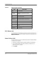
What Is in This Guide
The following outlines the organization of the SMARTMIM-216
Management Module Guide:
9032248 E1
Chapter
Description
Chapter 1
Introduction
Describes the device, the management module
software, and model types. This chapter also
provides information on accessing device-specific
views.
Chapter 2
Device Views
Describes the Device views representing the
device.
Chapter 3
Configuration Views
Describes the Configuration views for the device
and the network management information
provided by the views.
Chapter 4
Event and Alarm Messages
Lists and explains the event and alarm messages
generated in the Event Log or Alarm Manager for
the device.
Chapter 5
Application Views
Describes the Application views for the device and
application-specific information for this device.
Preface
ix
Conventions
Conventions
This guide uses the following conventions:
• Menu selections and buttons referenced in text appear in bold; for
example, Configuration or Detail.
• Button names appear in shadowed boxes when introducing paragraphs
describing their use; for example:
Help
• Menu navigation appears in order of selection; for example, Icon
Subviews -> Utilities -> Application.
• Referenced chapter titles and section headings appear in italics.
• Referenced documents appear in bold italics.
• SMARTMIM-216 is referred to as “device.”
• References in blue are hypertext links for on line documents.
Related SPECTRUM Documentation
When using this guide, you should have a clear understanding of SPECTRUM
functionality and navigation techniques as described in the following
recommended documentation:
Operator’s Reference
Administrator’s Reference
Report Generator User’s Guide
Application View Reference
Getting Started with SPECTRUM 4.0 for Operators
Getting Started with SPECTRUM 4.0 for Administrators
How to Manage Your Network with SPECTRUM
Preface
x
SMARTMIM-216
Management Module Guide
Other Related Documentation
Other Related Documentation
Refer to the following documentation for more information on managing TCP/
IP-based networks:
Martin, James, Kathleen Kavanagh Chapman, Joe Leben. Local Area
Networks: Architectures and Implementations, 2d ed. Englewood Cliffs,
NJ: Prentice Hall, 1994.
Rose, Marshall T. The Simple Book: An Introduction to Management of
TCP/IP-based Internets. Englewood Cliffs, NJ: Prentice Hall, 1991.
Stallings, William. Data and Computer Communications, 4th ed. New
York: Macmillan Publishing Company, 1994.
Tanenbaum, Andrew S. Computer Networks, 3d ed. Englewood Cliffs, NJ:
Prentice Hall, 1996.
9032248 E1
Preface
xi
Other Related Documentation
Preface
xii
SMARTMIM-216
Management Module Guide
Chapter 1
Introduction
What Is in This Chapter
This chapter introduces the SPECTRUM management module covering the
SMARTMIM-216. It describes the following:
• SMARTMIM-216
• SPECTRUM Device Management
- Accessing SPECTRUM Views
• SPECTRUM Views Roadmap
• SPMA Support
SMARTMIM-216
The SMARTMIM-216 is a 16-port high performance Ethernet switching
module with Fast Ethernet uplinks. It features fourteen 10Base-T front panel
ports, which are supported by RJ-45 connectors, and two optional 100Base-TX
or multi-mode fiber 100Base-FX uplinks using Fast Ethernet Port Interface
modules (FEPIMs).
The SMARTMIM-216 offers both Switched and Fast ethernet connectivity to
the MMAC-FNB (Flexible Network Bus), while ensuring connectivity to
existing Media Interface Modules (MIMs). Full duplex support on all
interfaces, with support for IEEE Auto-Negotiation on the 100Base-TX ports
is featured. The product also supports a unique Port Mirroring function,
allowing analyzers to be connected to individual or multiple ports on the
switch. In addition, port trunking, via Cabletron SmartTrunk or SecureFast
Virtual Networking, delivers high-bandwidth inter-switch links and traffic
load balancing.
9032248 E1
1-1
SPECTRUM Device Management
SPECTRUM Device Management
SPECTRUM management modules are software packages that provide
templates for creating models of devices. These templates, called model types,
specify attributes that correspond to objects defined in the Management
Information Bases (MIBs) which govern the operation of the device or
application to be modeled.
SpectroGRAPH uses modified window’s views to graphically display these
models as icons. These icons provide color-coded status information and
double-click access to other views that contain detailed configuration and
performance information. The models that are represented by these icons
reside in the SpectroSERVER database, where they are continuously updated
with new information retrieved during the polling cycle. The model type name
of the device for this management module is SMARTMIM-216.
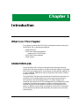
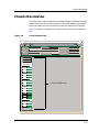
Accessing SPECTRUM Views
Access these views using double click zonesIcons and labels that display
information within an icon, provide access to SPECTRUM views. This is done
using double-click zones (Figure 1-1) or Icon Subviews menus (Figure 1-2).
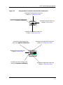
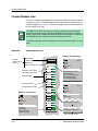
To access the Icon Subviews menu as shown in Figure 1-2, and Figure 1-3 do
the following:
1. Highlight the icon.
2. From the View menu, select Icon Subviews or click the applicable mouse
button (middle or right). Refer to the Operator’s Reference for
information on configuring your mouse.
Introduction
1-2
SMARTMIM-216
Management Module Guide
SPECTRUM Device Management
Accessing SPECTRUM Views
Figure 1-1.
Using Double-Click Zones to Access SPECTRUM Views
Accesses the Configuration views; see
Chapter 3, Configuration Views.
Accesses the Device Topology view;
refer to the Operator’s Reference.
Model Name
Accesses the Device views; see
Chapter 2, Device Views.
SmartMIM_216
Accesses the Application views; see
Chapter 5, Application Views.
Accesses the Performance view;
refer to the Operator’s Reference.
Accesses the Device views; see
Chapter 2, Device Views.
Accesses the Configuration views; see
Chapter 3, Configuration Views.
Model Name
SmartMIM_216
Accesses the Device Topology view;
refer to the Operator’s Reference.
9032248 E1
Accesses the Application views; see
Chapter 5, Application Views.
Introduction
1-3
SPECTRUM Device Management
Accessing SPECTRUM Views
Figure 1-2.
Using the Icon Subviews Menu to Access SPECTRUM Views
Model Name
SmartMIM_216
View
Ctrl+b
Go Back
Go Up
Icon Subviews
View Path
New View
Bookmarks
View History
Current View Info...
Notes...
Jump by name...
Zoom
Map Hierarchy
Figure 1-3.
Ctrl+c
Close
Navigate
Alarms
Performance
Notes...
Utilities
Zoom
Device
Chassis
DevTop
Interface
Physical
Accessing Device-Specific Subviews
1
SmartMIM_216
Bridging
Introduction
1-4
1
FWD
2
FWD
Close
Ctrl+c
Navigate
Alarms
Performance
Notes...
Utilities
Bridge Performance
Bridge Model Information
Special Database
Spanning Tree Information
Static Database Table
Transparent Bridge Info
Common
Device-Specific
SMARTMIM-216
Management Module Guide
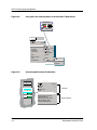
SPECTRUM Views Roadmap
SPECTRUM Views Roadmap
Figure 1-4 shows a “roadmap” of the SPECTRUM views for this device. These
views are accessible from double-click zones (Figure 1-1) and Icon Subviews
menus (Figure 1-2 and Figure 1-3).
9032248 E1
Introduction
1-5
SPECTRUM Views Roadmap
Figure 1-4.
SPECTRUM Views Roadmap
Performance View; refer to the
Operator’s Reference.
Interface Device View
Device Views; see Chapter 2,
Device Views.
Chassis Device View
Physical Device View
CSIIfPort Configuration View
Configuration Views; see
Chapter 3, Configuration
Views.
Device Configuration View
Model Name
SmartMIM_216
DevTop View; refer to
the Operator’s
Reference.
Fast Ethernet Application
DownLoad Application
Bridging Application; refer to
the Application View
Reference.
Application Views; see
Chapter 5, Application
View.
MIB II Application; refer to the
Application View Reference.
RS-232 Application; refer to the
Application View Reference.
RMON Application; refer to
the Management Module
Guide for Standard RMON.
Introduction
1-6
SMARTMIM-216
Management Module Guide
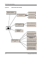
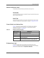
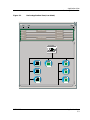
SPMA Support
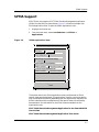
SPMA Support
SPECTRUM also supports SPECTRUM Portable Management Application
(SPMA) functionality for these devices. Figure 1-5 shows an example of an
SPMA Applications view. To open the SPMA Applications view:
1. Highlight the Device icon.
2. From the View menu, select Icon Subviews -> Utilities ->
Applications.
Figure 1-5.
SPMA Applications View
Applications
Bridging of type CSIBridge
Basic Alarms
Bridge View
MIB-II of type SNMP2_Agent
Generic SNMP (MIB I II)
Download App of type CtDownLoadApp
TFTP Download
Standard RMON of type RMONApp
RMON Load Monitor
RMON Protocol Analyzer
E Probe 0.1 of type RMONEthProbe
RMON Load Monitor
RMON Protocol Analyzer
Close
The buttons within the SPMA Applications view provide access to SPMAspecific views and dialog boxes. The Applications view for a particular device
may include different buttons depending upon the applications available, the
BRIMs installed, and the configuration of the device. Refer to the following
documentation for information on the SPMA views accessible from the
Applications view:
SPECTRUM Portable Management Application for the SmartMIM-216
User’s Guide
SPECTRUM Portable Management Application Tools Guide.
9032248 E1
Introduction
1-7
SPMA Support
Introduction
1-8
SMARTMIM-216
Management Module Guide
Chapter 2
Device Views
What Is in This Chapter
This chapter describes the following Device views and subviews available for
the SMARTMIM-216:
• Interface Device view
• Chassis Device view
• Physical Device view
See Chapter 1, Introduction, for information on accessing SPECTRUM views
from the Device icon and accessing device-specific subviews.
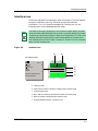
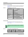
Interface Device View
This section describes the Interface icons and the Interface Options panel
displayed in the Interface Device view. This view provides dynamic
configuration and performance information for each interface on the device. If
the configuration changes, SPECTRUM modifies the Device view after the
next polling cycle to reflect the new configuration. This view also provides a
Device icon that allows you to monitor the device operation and to access other
device-specific views. Figure 2-1 shows an example of the Interface Device
view for the SMARTMIM-216.
9032248 E1
2-1
Interface Device View
Figure 2-1.
Interface Device View
Primary Landscape of type SmartMIM_216
* File
View
Help?
Model
System Up Time
Network Address
Manufacturer
Contact
Device Type
Description
Location
Primary Application
Serial Number
Bridging
Model Name
Filter
Network Information
Physical
Interface Description
SmartMIM_216
Device Icon
1
ON
ADDRESS
Interface Options Panel
5
ON
9
ON
13
ON
ETHERNET
ETHERNET
ETHERNET
ETHERNET
0:01D:17:2F:B6
0:01D:17:2F:BE
0:01D:17:2F:C2
0:01D:17:2F:CA
0
6 ON
0
10 ON
0
14 ON
134.141.59.20
1
2 ON
ETHERNET
ETHERNET
ETHERNET
ETHERNET
0:01D:17:2F:B7
0:01D:17:2F:BF
0:01D:17:2F:C3
0:01D:17:2F:CB
0
3 ON
7
0
ON
11
0
ON
0
15 ON
ETHERNET
ETHERNET
ETHERNET
ETHERNET
0:01D:17:2F:B8
0:01D:17:2F:BG
0:01D:17:2F:C4
0:01D:17:2F:CC
4
0
ON
8
0
ON
12
0
ON
16
0
ON
ETHERNET
ETHERNET
ETHERNET
ETHERNET
0:01D:17:2F:B9
0:01D:17:2F:BH
0:01D:17:2F:C5
0:01D:17:2F:CD
0
Device Views
2-2
0
0
Interface Icons
0
SMARTMIM-216
Management Module Guide
Interface Device View
Interface Icon
Interface Icon
These icons represent the interfaces or ports of the device. The icons identify
the type of interface or port (e.g., Ethernet) and provide statistical
information. Figure 2-2 shows an example of an Interface icon, its Icon
Subviews menu, and its labels/double-click zones.
NOTE
Figure 2-2.
The labels (a through f) displayed in the illustration below identify the label
name, and when applicable, the view to which it provides double-click access.
Example: (b) Administrative Status Label/Port Configuration-CSIIfPort View
displays the Administrative Status and provides double-click access to the
Port Configuration-CSIIfPort View. The menu on the left is the Icon Subviews
Menu for that Interface icon.
Interface Icon
(a)
(b)
Icon Subviews Menu
Close
Ctrl + c
Navigate
Alarms
Performance
Notes...
Utilities
Configuration
Seconday Address Panel
Model Information
ON
1
ETHERNET
0:0:1D:F:FD:B6
(c)
(d)
134.141.59.20
1
(e)
(f)
a. Interface Label
b. Administrative Status Label/Port Configuration-CSIIfPort View
c. Interface Type Label
d. MAC Address Label/CSI Interface Port Model Information View
e. Network Address Label/Secondary Address Panel
f.
9032248 E1
Gauge Label/Performance - CSIIfPort View
Device Views
2-3
Interface Device View
Interface Icon
Interface Icon Subviews Menu
Table 2-1 describes the Interface icon’s device-specific subviews menu
selections. For information on accessing device-specific subviews menus, see
Chapter 1, Introduction.
Table 2-1.
Interface Icon Subviews Menu
Menu Selection
Description
Configuration
Opens the Device Configuration view described
on page 3-2.
Secondary Address Panel
Opens the Secondary Address Panel view
described on page 2-7.
Model Information
Opens the Model Information view described in
the Operator’s Reference.
Interface Label
This label displays the interface (port) number.
Administrative Status Label
This label displays the status of this interface. Double-click this label to open
the Port Configuration - CSIIfPort view described on page 3-4. Table 2-2 and
Table 2-3 list the possible states relative to the application selected (Physical
or Bridging). The default application for this view is Physical (MIB-II). To
select the application to be displayed, click the Filter menu button in the
Interface Options panel. (Refer to the Interface Options Panel described on
page 2-7 for more information on the Filter menu button.)
Table 2-2.
Administrative Status for the Physical or MIB II Application
Color
Device Views
2-4
Status
Description
Green
ON
Port is operational.
Blue
OFF
Port is off.
Red
TST
Port is in the test mode.
SMARTMIM-216
Management Module Guide
Interface Device View
Interface Icon
Table 2-3.
Administrative Status for the Bridging Application
Color
Status
Description
Green
FWD
bridge port is forwarding
Blue
DIS
port is disabled
Magenta
LST
bridge is in the listening mode
Magenta
LRN
bridge is in the learning mode
Orange
BLK
bridge port is in the blocking mode
Red
BRK
bridge port is broken
Blue
UNK
status is unknown
Interface Type Label
This label displays the interface type. Table 2-4 lists the possible interface
types.
Table 2-4.
Interface Types
Type
9032248 E1
Description
Other
None of the following
Reg1822
Regular 1822
HDH1822
HDLC Distant Host protocol
DDNX25
Defense Data Network X.25
rfc877X25
RFC877 X.25
Ethernet
Ethernet CSMA/CD
iso88023
ISO CSMA/CD
iso88024
ISO token bus
iso88025
ISO token ring
iso88026
ISO man
starLan
StarLAN IEEE 802.3
Prot10MB
ProNET 10 Mbps
Prot80MB
ProNET 80 Mbps
HyChan
Hyperchannel
FDDI
Fiber Distributed Data Interface
LAPB
X.25 Line Access Procedure, Balanced
SDLC
IBM Synchronous Data Link Control protocol
T1
T1 link (USA and Japan)
Device Views
2-5
Interface Device View
Interface Icon
Table 2-4.
Interface Types (Continued)
Type
Description
CEPT
T1 link (Europe)
BasicISDN
Basic Integrated Services Digital Network
PrimISDN
Proprietary Integrated Services Digital
Network
PPSerial
Proprietary Point to Point Serial
PPP
Point to Point Protocol
SFTWARLPBK
Software Loopback
CLNPoverIP
Connectionless Network Protocol over IP
Enet3MB
Ethernet 3 Mbps
XNSoverIP
Xerox Network Service Protocol over IP
SLIP
Generic Serial Line IP
ULTRA
ULTRA Technologies
T-3
T3 link
SMDS
Switched Multimegabit Data Service
FrameRelay
T1 Frame relay
MAC Address Label
This label displays the MAC address of the device interface. Double-click this
label to open the CSI Interface Port Model Information view, described in the
Operator’s Reference.
Network Address Label
This label displays the current IP address of the interface. To select a different
IP address for this interface:
1. Double-click the label to open the Secondary Address Panel dialog box.
2. From the Address/Mask table, select the desired IP address entry to
replace the current IP address.
3. Click Update.
Device Views
2-6
SMARTMIM-216
Management Module Guide
Interface Device View
Interface Options Panel
Secondary Address Panel
This panel allows you to view and change the current IP address and mask for
the device. The Secondary Address Panel includes a table of IP addresses and
masks. Information displayed in this table is obtained from the Address
Translation table within the device’s firmware. The Secondary Address Panel
provides the following field and button.
IP Address
Displays the current IP Address for this interface.
Update
This button allows you to save changes made to the current IP Address of the
interface.
See Network Address Label for instructions on how to change the current IP
address for the selected interface.
Gauge Label
This label displays the performance statistic determined by the Gauge Control
Panel for this interface. (See Gauge Control Panel described on page 2-8 for
more information.) Double-click this label to open the Performance - CSIIfPort
view described in the Operator’s Reference.
Interface Options Panel
This area of the Interface Device view (see Figure 2-1) allows you to modify
the presentation of a highlighted icon. Double-click a non-text area of this
panel to open the Gauge Control Panel view described later in this chapter.
The Interface Options panel provides the following information.
Filter
This menu button allows you to select the application to be displayed by the
Interface icons. You can select other applications such as IP routing if the
SPECTRUM Routing Services Management Module is loaded. For more
information, refer to the Routing Services Management Module Guide.
Network Information
This menu button allows you to select the type of information displayed in the
Network Information label of the highlighted icon. Possible selections are
ADDRESS, NAME, or MASK.
9032248 E1
Device Views
2-7
Interface Device View
Gauge Control Panel
Interface Description
This field provides a description of the highlighted interface. If no interface is
highlighted, this field is empty or shows the interface previously highlighted.
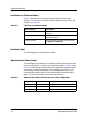
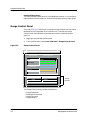
Gauge Control Panel
This view (Figure 2-3) allows you to change the type of statistical information
displayed on the Gauge label of the Interface icon. To access the Gauge
Control Panel view, double-click the background of the Interface Options
panel, or:
1. Highlight the Interface Options panel.
2. From the View menu, select Icon Subviews -> Gauge Control Panel.
Figure 2-3.
Gauge Control Panel
Gauge Control Panel
Gauge Mode
Rates
Totals
Percentages
Gauge Type
Numeric
Linear
Selected Attribute
Load
Load In
Load Out
Packet Rate
In Packet Rate
Out Packet Rate
% Discard
% Filtered
Apply
Keep Settings
Reset
Close
Gauge
Buttons
Default
The Gauge Control Panel provides the following:
•
•
•
•
Device Views
2-8
Gauge Mode area
Selected Attribute area
Gauge Type area
Gauge buttons
SMARTMIM-216
Management Module Guide
Interface Device View
Gauge Control Panel
Gauge Mode
This area allows you to select the type of information shown on the Gauge
label of the Interface icon: Rates, Totals, or Percentages. The Percentages
selection displays the percentage of the selected interface compared to the rest
of the interfaces.
The color displayed on the Gauge label depends upon the particular mode and
statistical attribute selected. Table 2-5 and Table 2-6 list the attributes and
their corresponding colors for the Totals mode and Rates mode, respectively.
Table 2-5.
Totals Mode: Attributes and Corresponding Color
Selected Attribute
Table 2-6.
Errors
Orange
In Packets
Blue
Out Packets
Blue
In Octets
Green
Out Octets
Green
Discards
Tan
Forwarded
Purple
Host Bound
Yellow
Transmitted
White
Filtered
Gray
Rates Mode: Attributes and Corresponding Color
Selected Attribute
9032248 E1
Color
Color
Load
Green
Load In
Green
Load Out
Green
Packet Rate
Blue
In Packet Rate
Blue
Out Packet Rate
Blue
%Discard
Tan
%Filtered
Gray
%Forwarded
Violet
%Host Bound
Yellow
%Error
Orange
%Transmitted
White
Device Views
2-9
Interface Device View
Gauge Control Panel
Selected Attribute
This area allows you to select the statistical attribute displayed on the
Interface icon’s Gauge label. The label changes color to reflect the attribute
selected.
Gauge Type
This area allows you to select either a numeric or linear display on the Gauge
label.
Gauge Buttons
The following describes the Gauge buttons:
Apply
Applies the current settings to the Gauge label for as long as the view is open.
Keep Settings
Saves the current settings while SpectroGRAPH is running. Settings return to
default when you restart SpectroGRAPH.
Reset
Returns the settings to the previously saved values.
Close
Closes the Gauge Control Panel view.
Default
Returns the settings to the SPECTRUM default.
Device Views
2-10
SMARTMIM-216
Management Module Guide
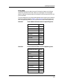
Chassis DeviceView
Chassis DeviceView
This view uses a Chassis Module icon to provide a logical representation of the
module chassis and its interfaces or ports. The Chassis Module icon provides
menu and double-click zone access to the views that monitor the interfaces.
Figure 2-4 shows an example of the Chassis Device view for the SmartMIM216.
Figure 2-4.
Chassis ModuleView
Landscape of type SmartMIM_216
*
File
View
Model Name
Contact
Description
Location
Help?
Net Address
Primary Application
Bridging
System Up Time
Manufacturer
Device Type
Serial Number
1
SmartMIM_216
Bridging
1
2
3
4
5
6
7
8
9
10
11
12
13
14
15
16
9032248 E1
FWD
FWD
FWD
FWD
FWD
FWD
FWD
Chassis Module Icon
FWD
FWD
FWD
FWD
FWD
FWD
FWD
FWD
FWD
Device Views
2-11
Chassis DeviceView
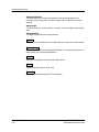
Chassis Module Icon
Chassis Module Icon
This icon is a logical representation of the physical device and its front panel
interfaces or ports. This section describes the information available from the
Chassis Module icon. Figure 2-5 shows an example of the Chassis Module icon
for the SMARTMIM-216.
NOTE
The labels to the left of the illustration identify the label names and when
applicable, the view to which they provide double-click access. For example,
Model Type/Device Configuration View displays the device model number and
provides double-click access to the Device Configuration View.
The menus displayed in the illustration are the Icon Subviews menus for that
label.
Figure 2-5.
Chassis Module Icon
Bridging Icon Subviews
Module
Identification
Labels
Slot Number/
Module Notes
Model Type/
Device Configuration View
Bridging Access Label/
CSI Performance View
Interface Icons
Interface # Label
Interface Status Label
Module Icon Subviews
Close
Navigate
Alarms
Performance
Notes...
Utilities
Module Notes
Application
Configuration
Model Information
Application Display
Alt+F4
1
FWD
Close
Alt+F4
Navigate
Alarms
Performance
Notes...
Utilities
Bridge Performance
Bridge Model Information
Special Database
Spanning Tree Information
Static Database Table
Transparent Bridge Info
FWD
Interface Icon Subviews
SmartMIM_216
Bridging
1
2
3
4
5
6
7
8
9
10
11
12
13
14
15
16
FWD
FWD
FWD
FWD
FWD
FWD
FWD
FWD
FWD
FWD
Close
Navigate
Alarms
Performance
Notes...
Utilities
Zoom
Configuration
Alt+F4
FWD
FWD
Operational Mode Config...
FWD
FWD
Ports 1 through 14 only
Fast Ethernet Configuration
Ports 15 and 16 only
Device Views
2-12
SMARTMIM-216
Management Module Guide
Chassis DeviceView
Chassis Module Icon
Module Identification Labels
These labels provide the following information (see Figure 2-5):
Slot Number
Identifies the modules location in the MMAC chassis. Double-click this area to
open the Module Notes view.
Model Type
Identifies the type of module in this chassis. Double-click this area to access
the Device Configuration view, described in Chapter 3, Configuration Views.
Chassis Module Icon Subviews Menu
Table 2-7 lists each of the device-specific Icon Subviews menu selections
available for this device. For information on accessing device-specific
subviews, see Chapter 1, Introduction.
Table 2-7.
Module Icon Subviews Menu
Menu Selection
Description
Module Notes
Opens the Module Notes dialog box.
Application View
Opens the Application view described on page 5-2.
Configuration
Opens the Device Configuration view described on page 3-2.
Model Information
Opens the Model Information view described in the
Operator’s Reference.
Application Display
Opens the Application menu selection. This menu selection
allows you to select the physical or bridging application.
Bridging Access Label
This label provides access to the Bridging Icon Subviews menu. (see
Figure 2-5.) Double-click the Bridging Access label to open the CSI Bridging
Performance view described in the Operator’s Reference.
9032248 E1
Device Views
2-13
Chassis DeviceView
Chassis Module Icon
Bridging Icon Subviews Menu
Table 2-8 lists specific Icon Subviews menu selections for the Bridging Access
Label. For information on accessing device-specific subviews, see Chapter 1,
Introduction.
Table 2-8.
Bridging Application Subviews Menu
Menu Selection
Description
Bridge Performance
Opens the Performance view described in the
Operator’s Reference.
Bridge Detail
Opens the Detail view described in the Operator’s
Reference.
Bridge Model Information
Opens the Model Information view described in the
Operator’s Reference.
Special Database
Opens the Special Database view.
Spanning Tree
Information
Opens the Spanning Tree Information view
described in the Application View Reference.
Static Database Table
Opens the Static Database Table view described in
the Application View Reference.
Transparent Bridge Info
Opens the Transparent Bridge Information view,
with Forwarding Database and Port Tables
described in the Application View Reference.
Interface Labels
These labels identify the number and activity status of each port. (See
Figure 2-5.) Table 2-9 and Table 2-10 list the possible states relative to the
application selected.
NOTE
Table 2-9.
Double-clicking the interface status labels will produce an error message
informing the user that the Interface Performance View is not accessible from
this area.
Interface Status for the Bridging Application
Color
Device Views
2-14
Status
Description
Green
FWD
Bridge port is forwarding.
Blue
DIS
Port is disabled.
SMARTMIM-216
Management Module Guide
Chassis DeviceView
Chassis Module Icon
Table 2-9.
Interface Status for the Bridging Application (Continued)
Color
Table 2-10.
Status
Description
Magenta
LST
Bridge is in the listening mode.
Magenta
LRN
Bridge is in the learning mode.
Orange
BLK
Bridge port is in the blocking mode.
Red
BRK
Bridge port is broken.
Blue
UNK
The status is unknown.
Interface Status for the Physical (MIB II) Application
Color
Status
Description
Green
ON
Port is operational.
Blue
OFF
Port is off.
Red
TST
Port is in the test mode.
Interface Icon Subviews Menu
This menu’s Configuration option opens the Configuration dialog box, which
allows you to enable or disable the selected port. For information on accessing
device-specific subviews, see Chapter 1, Introduction. Also, there is a menu
option for Operational Mode Configuration, which allows the port to be
configured to Standard mode or Full Duplex mode (ports 1 through 14 only) or
Fast Ethernet Configuration, which is detailed in the SPECTRUM Portable
Management Application for the SMARTMIM-216 User’s Guide.
9032248 E1
Device Views
2-15
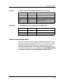
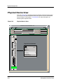
Physical Device View
Chassis Module Icon
Physical Device View
This icon (Figure 2-6) represents the physical device and the subviews menu
to the right of the device represents the menu options that can be accessed
from this device. See Chapter 1, Introduction, for more information on
accessing device-specific views.
Figure 2-6.
Physical Device View
Landscape of type SmartMIM_216
*
File
View
Help?
Net Address
Model Name
Contact
Description
Location
Primary Application
Bridging
System Up Time
Manufacturer
Device Type
Serial Number
SmartMIM-216
SN
CHM CPU
16
FE2|3
15
FE1|2
1
2
3
4
Physical Icon Subviews
5
6
7
8
1
2
9
10
11
12
13
14
15
16
1
Close
Navigate
Alarms
Performance
Notes...
Utilities
Application
Configuration
Model Information
Alt+F4
2
2
1
4
3
6
5
8
7
10
9
12
11
13
14
C
O
M
Smart SWITCH
ETHERNET
Device Views
2-16
SMARTMIM-216
Management Module Guide
Physical Device View
Chassis Module Icon
Table 2-11.
Physical Icon Subviews Menu
Menu Selection
9032248 E1
Description
Application
Opens the Application view described on page 5-2.
Configuration
Opens the Device Configuration view described on page 3-2.
Model Information
Opens the Model Information view described in the
Operator’s Reference.
Device Views
2-17
Physical Device View
Chassis Module Icon
Device Views
2-18
SMARTMIM-216
Management Module Guide
Chapter 3
Configuration Views
What Is in This Chapter
This chapter describes the Configuration views available for the SMARTMIM216 Module. These views display network configuration and operating
information for the device and its interfaces.
The following Configuration views are available for this device:
• Device Configuration View
• Port Configuration - CSIIfPort View
See Chapter 1, Introduction, for information on Accessing SPECTRUM Views
(page 1-2).
9032248 E1
3-1
Device Configuration View
Device Configuration View
This view provides device-specific configuration information as well as access
to other views that allow you to configure device components.
Device Configuration Information
This section of the Configuration view displays the following device-specific
information.
Contact Status
Indicates whether a connection with the device has been established.
This view also provides the following SPMA view buttons that allow you to
configure this device. Refer to the SPECTRUM Portable Management
Application Tools Guide for details on the views accessible from these
buttons.
Component Table
Opens the Community Name window, which provides information on the Fast
Ethernet SmartSwitch Module components.
Download Application
Opens the TFTP Download View, which enables you to upgrade the firmware
for a Fast Ethernet SmartSwitch Module from a TFTP Boot or Bootp Server.
Trap Table
Opens the Trap Table, which allows you to set up your workstation to be
notified of traps received and sent by the Fast Ethernet SmartSwitch Module.
Configuration Views
3-2
SMARTMIM-216
Management Module Guide
Device Configuration View
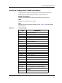
Interface Configuration Table Information
Interface Configuration Table Information
This table within the Device Configuration view provides the following
configuration information about the device’s interfaces or ports.
Number of Interfaces
Displays the number of interfaces or ports available for this device.
Index
Displays the interface or port number.
Type
Displays the type of hardware interface or port. Table 3-1 lists the possible
interface types.
Table 3-1.
Interface Types
Type
9032248 E1
Description
Other
None of the following
Reg1822
Regular 1822
HDH1822
HDLC Distant Host protocol
DDNX25
Defense Data Network X.25
rfc877X25
RFC877 X.25
Ethernet
Ethernet CSMA/CD
iso88023
ISO CSMA/CD
iso88024
ISO token bus
iso88025
ISO token ring
iso88026
ISO man
starLan
StarLAN IEEE 802.3
Prot10MB
ProNET 10 Mbps
Prot80MB
ProNET 80 Mbps
HyChan
Hyperchannel
FDDI
Fiber Distributed Data Interface
LAPB
X.25 Line Access Procedure, Balanced
SDLC
IBM Synchronous Data Link Control protocol
T1
T1 link (USA and Japan)
CEPT
T1 link (Europe)
BasicISDN
Basic Integrated Services Digital Network
PrimISDN
Proprietary Integrated Services Digital
Network
PPSerial
Proprietary Point to Point Serial
Configuration Views
3-3
Port Configuration-CSIIfPort View
Table 3-1.
Interface Types (Continued)
Type
Description
PPP
Point to Point Protocol
SFTWARLPBK
Software Loopback
CLNPoverIP
Connectionless Network Protocol over IP
Enet3MB
Ethernet 3 Mbps
XNSoverIP
Xerox Network Service Protocol over IP
SLIP
Generic Serial Line IP
ULTRA
ULTRA Technologies
T-3
T3 link
SMDS
Switched Multimegabit Data Service
FrameRelay
T1 Frame relay
Phy Address
Displays the physical (MAC) address of the interface or port.
Max Frame Size
Displays the maximum frame size for the interface or port.
Oper Status
Displays the current operational state of this interface or port (Up, Down, or
Testing).
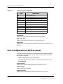
Port Configuration-CSIIfPort View
This view provides information on the configuration and operating status of
the device’s interfaces or ports. You can access this view from the Interface
Device view in two ways:
• Double-click the administrative status label.
• Highlight the Interface icon and from the Icon Subviews menu, select
Configuration.
Interface Index
Displays the numerical value identifying the interface or port.
Interface Type
Displays the type of interfaces.
Operation Status
Displays the current operating status of the port (On, Off, or Test).
Configuration Views
3-4
SMARTMIM-216
Management Module Guide
Port Configuration-CSIIfPort View
Admin Status
Provides a button that allows you to enable or disable this port. Possible
selections are On (enable), Off (disable), and Test.
If Description
Displays a description of the interface or port.
Operational Config
Sets the operational configuration to either half or full duplex.
Fast Ethernet Config
Sets the desired operational mode and sets advertised abilities.
9032248 E1
Configuration Views
3-5
Port Configuration-CSIIfPort View
Configuration Views
3-6
SMARTMIM-216
Management Module Guide
Chapter 4
Event and Alarm Messages
What Is in This Chapter
This chapter lists the types of events and alarms generated by the
SMARTMIM-216 Module and provides any probable cause messages
corresponding to these alarms.
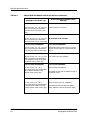
Device Events and Alarms
Table 4-1 lists the SPECTRUM database directory paths (in bold) and the
messages displayed for the Event Log and Alarm Manager when applicable.
Table 4-1.
SMARTMIM-216 Module Events and Alarms
Message in the Event Log
Alarm Manager Probable Cause
Message
CsEvFormat/Event00010306
No probable cause message
{d “%w- %d %m-, %Y - %T”} - A(n) {t}
device, named {m}, has been cold
started. (event [{e}])
CsEvFormat/Event00010307
No probable cause message
{d “%w- %d %m-, %Y - %T”} - A(n) {t}
device, named {m} has been warm
started, (event [{e}])
9032248 E1
4-1
Device Events and Alarms
Table 4-1.
SMARTMIM-216 Module Events and Alarms (Continued)
Message in the Event Log
Alarm Manager Probable Cause
Message
CsEvFormat/Event00010308
CsPCause/Prob00010308
{d “%w- %d %m-, %Y - %T”} - A(n) {t}
device, named {m}, has detected a
communication Link Down. (event
[{e}])
Communication link is down.
CsEvFormat/Event00010309
{d “%w- %d %m-, %Y - %T”} - A(n) {t}
device, named {m}, has detected a
communication Link Up. (event [{e}])
No probable cause message
CsEvFormat/Event0001030a
CsPCause/Prob0001030a
{d “%w- %d %m-, %Y - %T”} - A(n) {t}
device, named {m}, has detected an
Authentication Failure. (event [{e}])
Authorization failure. Other user is trying to
connect to device with an invalid community
string.
CsEvFormat/Event0001030b
CsPCause/Prob0001030b
{d “%w- %d %m-, %Y - %T”} - A(n) {t}
device, named {m}, has detected an
EGP Neighbor Loss. EGP Neighbor
IP address is {0 1}. (event [{e}])
Lost contact with EGP neighbor.
CsEvFormat/Event00010401
CsPCause/Prob00010401
{d "%w- %d %m-, %Y - %T"} Device {m} of type {t} is created with
an IP address already used by
another model. (event [{e}])
DUPLICATE IP ADDRESS
The model has the same IP address as that of
some other model.
CsEvFormat/Event00010402
CsPCause/Prob00010402
{d "%w- %d %m-, %Y - %T"} Device {m} of type {t} is created with
a physical (MAC) address already
used by another model. (event [{e}])
DUPLICATE PHYSICAL ADDRESS
Event and Alarm Messages
4-2
The model has the same Physical address
(MAC address) as that of some other model.
SMARTMIM-216
Management Module Guide
Chapter 5
Application Views
What Is in This Chapter
This chapter describes the device-specific applications listed below for the
SMARTMIM-216. The corresponding application model type is shown in
parentheses.
• Fast Ethernet (FastEnetApp)
• DownLoadApp (CtDownLoadApp)
Common Applications
This device supports the following common applications described in the
Application View Reference:
• Bridging(CSIBridge)
- Spanning Tree(Ct_Stp_App)
- Static (Static_App)
- Transparent (CT_Tp_Appl))
• MIB-II(SNMP2_Agent)
- )ICMP (ICMP_App)
- IP (IP2_App)
- System(System2_App)
- UDP (UDP2_App)
• RS-232 App (RFC1317App)
This device also supports the following service which is described in its
management module guide.
• Standard RMON (RMON App)
9032248 E1
5-1
Application View
- Ethernet Probe 1(RMONEthProbe) through Ethernet Probe 16
(RMONEthProbe)
Application View
The Application view displays information on any application supported by
the device. Each application appears as an icon in the Application view. Access
application-specific Model Information Views, Performance Views, and Detail
Views from these icons. Depending on the specific application, various
additional views are also available and discussed in this section.
Device Application View
This view shows the common and device-specific applications supported by
this device and provides access to application-specific information.
See Chapter 1, Introduction, for information on Accessing SPECTRUM Views.
Figure 5-1 shows an example of an Application view in the Icon mode.
Figure 5-2 shows an example of an Application view in the List mode.
To change the display mode, select View -> Mode -> List or Icon.
Application Views
5-2
SMARTMIM-216
Management Module Guide
Application View
Device Application View
Figure 5-1.
Device Application View (Icon Mode)
BANNERView of type SMARTMIM-216
*
File
Model Name
View
Help?
Network Address
Sys Up Time
Contact
Manufacturer
Description
Device Type
Location
Serial Number
Primary Application
Model Name
SmartMIM_216
Bridging
CSIBridge
Spanning Tree
Download App
MIB-II
CtDownload
SNMP2_Agent
CtDownload
SNMP2_Age
ICMP
ICMP_App
CT_Stp_App
Static
ICMP_App
IP
IP2_App
Static_App
9032248 E1
IP2_App
Application Views
5-3
Application View
Figure 5-2.
Device Application View (List Mode)
BannerView of type SMARTMIM-216
*
File
Model Name
View
Help?
Network Address
Contact
Manufacturer
Description
Location
Sys Up Time
Device Type
Primary Application
Serial Number
SMARTMIM-216
CSIBridge
Ct_Stp_App
Static_App
CT_Tp_App
SNMP2_Agent
ICMP_App
IP2_App
System2_App
UDP2_App
Application Views
5-4
SMARTMIM-216
Management Module Guide
Fast Ethernet Application View
Fast Ethernet Port Table
Fast Ethernet Application View
This section describes the Fast Ethernet Application view supported by the
SMARTMIM-216. The Fast Ethernet uses FastEnetApp as the corresponding
model type name. The application provides the Fast Ethernet Port Table and
the Fast Ethernet Configuration view, which allows you to configure ports for
Ethernet or Fast Ethernet transmissions or use auto-negotiation to determine
transmission mode.
Fast Ethernet Port Table
To access this table:
1. Highlight the FastEnetApp icon (Icon Mode) or text label (List Mode).
2. From the Icon Subviews menu select Control Table.
The Fast Ethernet Port Table provides the following information:
Interface
Displays the interface number for which this Fast Ethernet information
pertains.
Port Group
Displays the port group number for which this Fast Ethernet information
pertains.
Port
Displays the physical port number for which this Fast Ethernet information
pertains.
Operational Mode
Displays the current operational mode of this port.
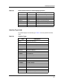
Fast Ethernet Configuration View
The Fast Ethernet Configuration view allows you to configure ports for
Ethernet or Fast Ethernet transmission or to use Auto-Negotiation in
determining transmission mode. To access this view, double-click any entry in
the Fast Ethernet Port Table. The Fast Ethernet Configuration view carries
the Interface, Port Group, and Port information over from the Control Table
(see Figure 5-3).
9032248 E1
Application Views
5-5
Fast Ethernet Application View
Fast Ethernet Configuration View
Figure 5-3.
Fast Ethernet Configuration View
132.127.118.24 of type SMARTMIM-216
*
File
View
Help?
Net Addr
Model Name
132.127.118.24
Sys Up Time
Contact
Manufacturer
Description
Cabletron 8H02-16 Rev 01.01.04 SmartSwitch 10/100
Location
Primary Application
Interface
Port Group
SS8H
Device Type
Serial Number
Port
Operational Mode
Auto-Negotiation
100BaseTX
100BaseFX
10BaseT
100BaseTXFD
100BaseFXFD
10BaseTFD
100BaseT4
Advertised Ability
10BaseT
100BaseTXFD
10BaseTFD
100BaseT4
100BaseTX
100BaseFX
100BaseFXFD
Received Technology
Undefined
Auto-Negotiation
Not-Detected
10BaseT
10BaseTFD
100BaseTX
100BaseTXFD
100BaseT4
100BaseFX
100BaseFXFD
Operational Mode
This field indicates the current operational mode of this port. If you select
auto-negotiation, you can select as many modes as needed from the Advertised
Ability selections. You can only select one Operational Mode; either autonegotiation or one of the specific modes. Table 5-1 shows the current
operational modes, their values, and descriptions.
Application Views
5-6
SMARTMIM-216
Management Module Guide
Fast Ethernet Application View
Fast Ethernet Configuration View
Table 5-1.
Current Operational Mode Values and Descriptions
Operational
Mode
Value
Description
Auto-Negotiation
2
Auto-Negotiation/Parallel Detection
10Base-T
8
10Base-T
10Base-TFD
16
Full duplex 10Base-T
100Base-TX
32
100Base-TX
100Base-TXFD
64
Full duplex 100Base-TX
100Base-T4
128
100Base-T4
100Base-FX
256
100Base-FX
100Base-FXFD
512
Full Duplex 100Base-FX
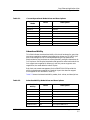
Advertised Ability
This field indicates the advertised ability of the local hardware for ports that
have auto-negotiation enabled. Auto-Negotiation allows the FE-100TX RJ45
port to self-configure to 10 or 100 Mbps depending on the speed of the
attached device; the interfaces can also dynamically configure themselves for
Full Duplex or Half Duplex (standard mode) operation when both ends of the
link support auto-negotiation. When only one link partner supports autonegotiation, the mode defaults to Half Duplex.
Both local and remote management for the SMARTMIM-216 provide the
ability to disable auto-negotiation if desired. A port that does not support
auto-negotiation will be read as “other (1)”.
Table 5-2 shows the Advertised Ability modes, their values, and descriptions.
Table 5-2.
Advertised Ability Mode Values and Descriptions
Advertised
Ability
9032248 E1
Value
Description
10Base-T
8
10Base-T
10Base-TFD
16
Full Duplex 10Base-T
100Base-TX
32
100Base-TX
100Base-TXFD
64
Full Duplex 100Base-TX
100Base-T4
128
100Base-T4
100Base-FX
256
100Base-FX
100Base-FXFD
512
Full Duplex 100Base-FX
Application Views
5-7
Download Application
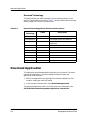
Received Technology
This field indicates the advertised ability of the remote hardware, or link
partner. These modes are read-only. Table 5-3 shows the Received Technology
Ability modes, their values, and descriptions.
Table 5-3.
Received Technology Ability Values and Descriptions
Received
Technology
Value
Description
Undefined
1
Undefined
Auto-Negotiation
2
Auto-Negotiation/Parallel Detection
Not-Detected
4
Link Partner does not support AutoNegotiation
10Base-T
8
10Base-T
10Base-TFD
16
Full duplex 10Base-T
100Base-TX
32
100Base-TX
100Base-TXFD
64
Full duplex 100Base-TX
100Base-T4
128
100Base-T4
100Base-FX
256
100Base-FX
100Base-FXFD
512
Full duplex 100Base-FX
Download Application
This application provides download functionality for this device. The model
type for this application is CtDownLoadApp. Access the DownLoad
Application view as follows:
1. Within the Application view, highlight the CtDownLoadApp icon (icon
mode) or model type name (list mode).
2. From the Icon Subviews menu, select Download Application.
The Download Application view is an SPMA view and is described in the
SPECTRUM Portable Management Application Tools Guide.
Application Views
5-8
SMARTMIM-216
Management Module Guide
Index
A
Accessing
SPECTRUM Views 1-2, 1-5
Address
MAC 2-3, 2-6, 3-4
Network 2-7
Admin Status 3-5
Administrative Status Label 2-4
Alarm Messages 4-1
Application View 5-1
Attribute Selected 2-9
B
Bridging Access Label 2-13
Bridging Application Interface Status 2-14
C
Chassis Device View 2-1, 2-11
Bridging Icon Subviews Menu 2-14
Interface Icon Subviews Menu 2-15
Chassis Manager Application View 5-4
Community
String Configuration View 5-6
Component Table
Accessing 3-2
Button 3-2
Configuration Information 2-1
Configuration Views 3-1
Device 3-1, 3-2
Port Configuration CSIIfPort 3-1, 3-4
Control Table
Advertised Ability 5-7
Operatonal Mode 5-5
Received Technology 5-8
CSIIfPort
Configuration 3-4
Device Application View
Icon mode 5-2
List mode 5-2
Device Configuration View 3-2
Interface Configuration Table 3-3
Device Views 2-1
Chassis 2-1, 2-11
Interface 2-1, 2-2
Physical 2-1
documentation
conventions x
organization ix
Download Application
Accessing 3-2
Button 3-2
DownLoadApp (CtDownLoadApp) 5-1
E
Environmental Device View 2-11
Event Messages 4-1
F
Fast Ethernet Configuration view 5-5
Fast Ethernet SmartSwitch Module 1-1
Fast Ethernet(FastEnetApp) 5-1
Filter 2-7
G
Gauge
Buttons 2-10
Control Panel 2-8
Label 2-7
Logical 2-3
Mode 2-10
Selected Attribute 2-10
Type 2-10
Getting Help xi
D
Default Button 2-10
9032248 E1
1
H
N
HDLC 2-5
Name
Network 2-7
Network
Information 2-3, 2-7
Network Information Label 2-6
Notice i
I
Icon Modification 2-7
IF Description 3-5
Interface
Bridging Application Status 2-14
Configuration Table 3-3
Description 2-8
Icon, Device View 2-3
Monitoring 2-11
Number 2-3
Options Panel 2-7
Status of 2-4
Type 2-5, 3-3, 3-4
Interface Device View 2-1, 2-2
Interface Icon, Device View
Administrative Status Label 2-4
Gauge Label 2-7
Illustration 2-3
Interface Number label 2-4
Interface Type Label 2-5
MAC Address Label 2-6
Network Information Label 2-6
Interface Label 2-4, 2-14
Interface Number Label 2-4
Interface Options Panel 2-10
Interface Type label 2-3
K
Keep Settings Button 2-10
L
Label and Double-Click Zones 2-3
M
MAC
Address
Label 2-3
MAC Address Label 2-6
Mask
Network 2-7
Index
2
O
Operation Status 3-4
Operational Status 2-1
P
Performance Information 2-1
Performance Statistics 2-7
Port
Configuration
View 3-4
Port Configuration CSIIfPort View 3-4
Port Status 2-14
R
Related Reading xi
Restricted Rights Notice ii
RMON 5-1
RS-232 App 5-1
S
SMARTMIM-216 1-1
SMARTMIM-216 Management Module
Guide
ix
SPECTRUM Device Management 1-2
SPECTRUM Portable Management App 1-7
SPMA Applications 1-7
Statistical Information 2-3
Status
Administrative 2-3
T
TCP/IP Based Networks xi
Trademarks i
Trap Table
SMARTMIM-216
Management Module Guide
Accessing 3-2
Button 3-2
V
Virus Disclaimer i
Z
Zones, Double-Click and Label 2-3
9032248 E1
Index
3
Index
4
SMARTMIM-216
Management Module Guide