1
SPECTRUM Enterprise Manager
Device Management
Titlepae
SmartSwitch 2000
Supports Management Module SM-CSI1068/80/87
SPECTRUM Enterprise Manager
Page 2
SmartSwitch 2000
Notice
Restricted Rights Notice
Cabletron Systems reserves the right to make changes in specifications and other
information contained in this document without prior notice. The reader should in all
cases consult Cabletron Systems to determine whether any such changes have
been made.
(Applicable to licenses to the United States Government only.)
1. Use, duplication, or disclosure by the Government is subject to restrictions as
set forth in subparagraph (c) (1) (ii) of the Rights in Technical Data and
Computer Software clause at DFARS 252.227-7013.
The hardware, firmware, or software described in this manual is subject to change
without notice.
Cabletron Systems, Inc., 35 Industrial Way, Rochester, New Hampshire 03866.
2. (a) This computer software is submitted with restricted rights. It may not be
used, reproduced, or disclosed by the Government except as provided in
paragraph (b) of this Notice or as otherwise expressly stated in the contract.
IN NO EVENT SHALL CABLETRON SYSTEMS BE LIABLE FOR ANY
INCIDENTAL, INDIRECT, SPECIAL, OR CONSEQUENTIAL DAMAGES
WHATSOEVER (INCLUDING BUT NOT LIMITED TO LOST PROFITS) ARISING
OUT OF OR RELATED TO THIS MANUAL OR THE INFORMATION CONTAINED
IN IT, EVEN IF CABLETRON SYSTEMS HAS BEEN ADVISED OF, KNOWN, OR
SHOULD HAVE KNOWN, THE POSSIBILITY OF SUCH DAMAGES.
(b) This computer software may be:
(1) Used or copied for use in or with the computer or computers for which
it was acquired, including use at any Government installation to which
such computer or computers may be transferred;
Copyright © Copyright Date Here by Cabletron Systems, Inc. All rights reserved.
Order Number: 9032073-01
(2) Used or copied for use in a backup computer if any computer for which
it was acquired is inoperative;
Cabletron Systems, Inc.
(3) Reproduced for safekeeping (archives) or backup purposes;
Printed in the United States of America.
P.O. Box 5005
(4) Modified, adapted, or combined with other computer software, provided
that the modified, combined, or adapted portions of the derivative
software incorporating restricted computer software are made subject
to the same restricted rights;
Rochester, NH 03866-5005
SPECTRUM, the SPECTRUM IMT/VNM logo, DCM, IMT, and VNM are registered
trademarks, and SpectroGRAPH, SpectroSERVER, Inductive Modeling
Technology, Device Communications Manager, and Virtual Network Machine
are trademarks of Cabletron Systems, Inc.
(5) Disclosed to and reproduced for use by support service contractors in
accordance with subparagraphs (b) (1) through (4) of this clause,
provided the Government makes such disclosure or reproduction
subject to these restricted rights; and
Ethernet is a trademark of Xerox Corporation.
(6) Used or copied for use in or transferred to a replacement computer.
Virus Disclaimer
Cabletron Systems makes no representations or warranties to the effect that the
Licensed Software is virus-free.
Cabletron has tested its software with current virus checking technologies.
However, because no anti-virus system is 100% reliable, we strongly caution you to
write protect and then verify that the Licensed Software, prior to installing it, is
virus-free with an anti-virus system in which you have confidence.
(c) Notwithstanding the foregoing, if this computer software is published
copyrighted computer software, it is licensed to the Government, without
disclosure prohibitions, with the minimum rights set forth in paragraph (b) of
this clause.
(d) Any other rights or limitations regarding the use, duplication, or disclosure
of this computer software are to be expressly stated in, or incorporated in,
the contract.
(e) This Notice shall be marked on any reproduction of this computer software, in
whole or in part.
Device Management
Page 3
SmartSwitch 2000
Contents
PREFACE
6
Chassis Device View .................................................... 31
Chassis Device Icon.................................................. 33
Device Type Label ................................................. 34
Bridging Icon Subviews Menu ............................... 35
Interface Labels ..................................................... 36
Interface Icon Subviews Menu............................... 37
FDDI Label............................................................. 37
FDDI Icon Subviews Menu .................................... 37
Logical Ports Labels .............................................. 38
Logical Ports Icon Subviews Menu........................ 38
Physical Device View .................................................... 39
Conventions ....................................................................6
Related SPECTRUM Documentation .............................6
Other Related Documentation ........................................7
INTRODUCTION
8
SmartSwitch Modules .....................................................8
SPECTRUM Support ......................................................9
Accessing SPECTRUM Views from the Device Icon ..9
Accessing Device-Specific Subviews ........................11
SPECTRUM Views Roadmap.......................................13
SPMA Support ..............................................................15
DEVICE VIEWS
41
What Is in This Section ................................................. 41
Device Configuration View ............................................41
Device Configuration Information .............................. 41
Interface Configuration Table Information ................. 42
Port Configuration - CSIIfPort View .............................. 44
FddiMAC Device Configuration View............................ 45
Station Configuration................................................. 45
SMT Information........................................................ 48
Port Configuration View ................................................48
19
What Is in This Section .................................................19
Interface Device View ...................................................19
Interface Icon.............................................................21
Interface Icon Subviews Menu...............................22
Interface Label .......................................................23
Administrative Status Label ...................................23
Interface Type Label ..............................................24
MAC Address Label ...............................................26
Network Information Label .....................................26
Gauge Label ..........................................................26
Interface Options Panel .............................................26
Gauge Control Panel .................................................27
Document_Family (variable)
CONFIGURATION VIEWS
EVENT AND ALARM MESSAGES
51
Device Events and Alarms ............................................51
Page 4
Title (variable)
Contents
APPLICATION VIEWS
Contents
56
What Is in This Section .................................................56
Common Applications Not Covered Here .....................56
Device Application View................................................56
Interface Remap Application .........................................60
Fast Ethernet Application ..............................................63
Fast Ethernet Port Table ...........................................63
Fast Ethernet Configuration View ..............................63
Operational Mode ...............................................65
Advertised Ability ................................................65
Received Technology .........................................66
FDDI FNB Application ...................................................67
FDDI Station List View...............................................68
ATM Client Application..................................................69
ATM Client Application VCL View .............................70
Download Application View...........................................74
INDEX
Document_Family (variable)
76
Page 5
Title (variable)
Preface
• Referenced documents appear in bold italics.
Use this guide as a reference for the SPECTRUM
SmartSwitch Router management software.
Before using this guide, you should be familiar
with SPECTRUM’s functions and navigational
techniques as described in the Administrator’s
Reference and the Operator’s Reference.
Related SPECTRUM
Documentation
It is important when using this guide that you
have a clear understanding of SPECTRUM
functionality and navigation techniques as
described in the following recommended
documentation:
For the purposes of this guide, a SmartSwitch
Module is referred to as a “device.”
Conventions
Operator’s Reference
This guide uses the following conventions:
Administrator’s Reference
• Menu selections and buttons referenced in
text appear in bold;
bold for example,
Configuration or Detail.
Detail
Report Generator User’s Guide
Application View Reference
• Buttons appear as shadowed boxes when
describing their use; for example:
Getting Started with SPECTRUM for Operators
• Menu navigation appears in order of selection;
for example, Icon Subviews -> Utilities ->
Application.
Application
How to Manage Your Network with SPECTRUM
Getting Started with SPECTRUM for Administrators
This guide also references the following
documents:
• Referenced chapter titles and section
headings appear in italics.
Device Management
Page 6
SmartSwitch 2000
Preface
Other Related Documentation
SPECTRUM Portable Management Application
Tools Guide
SPECTRUM Routing Services Management
Module Guide
SPECTRUM Portable Management Application for
the 2E42 Fast Ethernet SmartSwitch User’s
Guide
Other Related Documentation
Refer to the following documentation for more
information on managing TCP/IP-based
networks:
Martin, James, Kathleen Kavanagh Chapman,
Joe Leben. Local Area Networks, Architectures
and Implementations, 2nd ed. Englewood Cliffs,
NJ: Prentice Hall, 1994.
Rose, Marshall T. The Simple Book — An
Introduction to Management of TCP/IP-based
Internets. Performance Systems International,
Inc.
Stallings, William. Data and Computer
Communications, 4th ed. New York: Macmillan
Publishing Company, 1994.
Tanenbaum, Andrew S. Computer Networks,
3rd ed. Englewood Cliffs, NJ: Prentice Hall, 1996.
Device Management
Page 7
SmartSwitch 2000
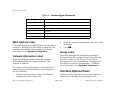
Introduction
Introduction
This section introduces the SPECTRUM management module covering the SmartSwitch Modules described
below.
What Is in This Section
The 8H02-16 is a 16-port device having 14
standard 10Base-T front panel ports that are
supported by RJ-45 connectors and two 100BaseTX or multi-mode fiber 100Base-FX uplinks using
Fast Ethernet Port Interface Modules.
It describes the following:
• SmartSwitch Modules
• SPECTRUM Support
- Accessing SPECTRUM Views from the
Device Icon
-
The 2E42-27 and 2E42-27R devices expand the
capabilities of the 8H02-16 by providing 27 ports
including 24 standard Ethernet ports with RJ-45
connectors, two slots for Fast Ethernet Port
Interface Modules, and one slot for a High Speed
Interface Module to provide a high-speed ATM
uplink or FDDI connectivity. The 2E42-27 has a
single power supply and the 2E42-27R has dual
redundant power supplies.
Accessing Device-Specific Subviews
• SPECTRUM Views Roadmap
• SPMA Support
SmartSwitch Modules
The 8H02-16, 2E42-27, 2E42-27R, 2E43-27, and
2E43-27R SmartSwitch Modules are all high
performance Ethernet switching devices that
provide Fast Ethernet uplinks.
Device Management
The 2E43-27 and 2E43-27R provide the same
feature set as the 2E42-27 and 2E42-27R but
come equipped with two RJ21 connectors to
support 24 ports of switched Ethernet rather than
Page 8
SmartSwitch 2000
Introduction
SPECTRUM Support
the 24 RJ45’s. This allows the use of Telco cables
in the wiring closets with patch panels to reduce
the complexity of cable management.
Accessing SPECTRUM Views
from the Device Icon
All five devices offer RMON, port redirection,
broadcast suppression, and full duplex support
on all interfaces, with support for IEEE AutoNegotiation on the 100Base-TX ports.
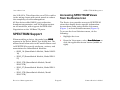
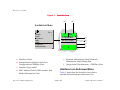
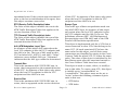
The Device icon provides access to SPECTRUM
views that display device-specific information.
Access these views using double-click zones
(Figure 1) or Icon Subviews menus (Figure 2).
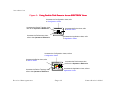
To access the Icon Subviews menu, do the
following:
SPECTRUM Support
1
Highlight the icon.
2
From the View menu, select Icon Subviews or
click the applicable mouse button (middle or
right).
Page 9
SmartSwitch 2000
When modeling a device, the model type SS8H
appears in the Select Model Type dialog box. The
names listed below refer to the model names used
in SPECTRUM to specify attributes, actions, and
associations for SmartSwitch Modules:
• 8H02_16 (SmartSwitch Module, Model 8H0216)
• 2E42_27 (SmartSwitch Module, Model 2E4227)
• 2E42_27R (SmartSwitch Module, Model
2E42-27R)
• 2E43_27 (SmartSwitch Module, Model 2E4327)
• 2E43_27R (SmartSwitch Module, Model
2E43-27R)
Device Management
Introduction
Figure 1: Using Double-Click Zones to Access SPECTRUM Views
Accesses the Configuration views; refer
to Configuration Views.
Accesses the Device Topology view;
refer to the Operator’s Reference.
Model Name
Accesses the Device views; refer
to Device Views.
8H02_16
Accesses the Performance view;
refer to the Operator’s Reference.
Accesses the Application views; refer
to Application Views.
Accesses the Configuration views; refer to
Configuration Views.
Accesses the Device views; refer
to Device Views.
Model Name
8H02_16
Accesses the Device Topology view;
refer to the Operator’s Reference.
Device Management
P a g e 10
Accesses the Performance view;
refer to the Operator’s Reference.
Accesses the Application views; refer to
Application Views.
SmartSwitch 2000
Introduction
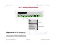
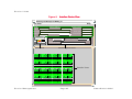
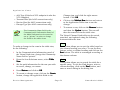
Figure 2: Using the Icon Subviews Menu to Access SPECTRUM Views
Model Name
8H02_16
View
Ctrl+b
Go Back
Go Up
Icon Subviews
View Path
New View
Bookmarks
View History
Current View Info...
Notes...
Jump by name...
Zoom
Map Hierarchy
Page
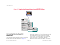
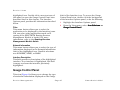
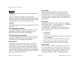
Accessing Device-Specific
Subviews
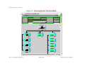
Icon Subviews menus provide access to views that
display device-specific information. Figure 3
Device Management
Close
Ctrl+c
Navigate
Alarms
Performance
Notes...
Utilities
Zoom
Device
Chassis
DevTop
Interface
shows an example of an Icon Subviews menu for
the Bridging icon located within the Chassis
Device view. The device-specific Icon Subviews
menu selections are described under the
applicable section within this guide. The menu
P a g e 11
SmartSwitch 2000
Introduction
selections that are common to all devices are
described in the Administrator’s Reference and
the Operator’s Reference.
To access the Icon Subviews menu using the View
menu, do the following:
1
Highlight the icon.
2
From the View menu, select Icon Subviews.
Subviews
To access the Icon Subviews menu using the
mouse button, do the following:
1
Position the mouse pointer on the icon.
2
Click the appropriate button, middle or right.
Device Management
P a g e 12
SmartSwitch 2000
Introduction
SPECTRUM Views Roadmap
Figure 3:
Accessing Device-Specific Subviews
2E42-27R
Bridging
1
FWD
2
FWD
3
FWD
4
FWD
5
FWD
6
FWD
7
FWD
Ctrl +C
Close
Navigate
Alarms
Performance
Notes...
Utilities
Bridge Performance
Bridge Detail
Bridge Model Information
Special Database
Spanning Tree Information
Static Database Table
Transparent Bridge Info
SPECTRUM Views Roadmap
8
FWD
Common
Device Specific
from double-click zones (Figure 1) and Icon
Subviews menus (Figure 2 and Figure 3).
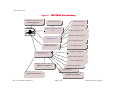
Figure 4 shows a “roadmap” of the SPECTRUM
views for this device. These views are accessible
Device Management
P a g e 13
SmartSwitch 2000
Introduction
Figure 4:
Performance View, refer to the
Operator’s Reference.
SPECTRUM Views Roadmap
Chassis Device View
Interface Device View
Physical Device View
Model Name
Device Views, refer to Device
Views.
FDDI Configuration View
8H02_16
CSIIfPort Configuration View
Configuration Views, refer to
Configuration Views.
Device Configuration View
DevTop View, refer to the
Operator’s Reference.
Port Configuration View
Fast Ethernet Application
Application Views, refer to
Application Views.
Interface Remap Application
DownLoad Application
Bridging Application, refer to the
Application View Reference.
ATM_Client Application
FDDI Application
MIB II Application, refer to the
Application View Reference .
Device Management
RS-232 Application, refer to the
Application View Reference.
P a g e 14
SmartSwitch 2000
Introduction
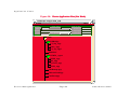
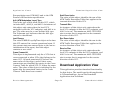
SPMA Support
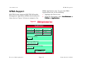
SPMA Support
SPMA Applications view. To open the SPMA
Applications view, do the following:
SPECTRUM also supports SPECTRUM Portable
Management Application (SPMA) functionality for
these devices. Figure 5 shows an example of an
1
Highlight the Device icon.
2
From the View menu, select Icon Subviews ->
Utilities -> Applications.
Applications
Figure 5:
SPMA Applications View
Applications
Example of type 8H02_16
Community Names
Frame Priorities
System Resources
Broadcast Suppression
MAC Priorities
Trap Table
Port Priorities
Basic Alarms
Bridging of type CSIBridge
Bridge View
MIB II of type SNMP2_Agent
Generic SNMP (MIB I II)
Download App of type CtDownLoadApp
TFTP Download
Close
Device Management
P a g e 15
SmartSwitch 2000
Introduction
The SPMA Applications view provides the buttons,
described below, that are used to access SPMAspecific views and dialog boxes. For more
information, refer to the SPECTRUM Portable
Management Application for the 2E42
SmartSwitch User’s Guide or the SPECTRUM
Portable Management Application Tools
Guide.
Device Management
P a g e 16
SmartSwitch 2000
Introduction
Community Names
MAC Priorities
This button accesses the Community Names Tool,
which allows you to change device community
names. Refer to Using the SPMA Community
Names Tool in the Tools Guide.
This button accesses the MAC Priorities window,
which allows you to set the priority in which
frames are queued by MAC address for
transmission by the device. Refer to the 2E42
User’s Guide.
Guide
Frame Priorities
This button accesses the Frame Priorities
window, which allows you to set the priority in
which frames types are queued for transmission
by the device. Refer to the 2E42 User’s Guide.
Guide
System Resources
This button accesses a window that displays
current physical and logical system resources
and utilizations on the device. Refer to the 2E42
User’s Guide.
Guide
Broadcast Suppression
This button allows you to monitor broadcast
traffic statistics on each interface and set
thresholds to limit broadcast traffic over the
device. Refer to the 2E42 User’s Guide.
Guide
Device Management
Trap Table
This button accesses the SNMP Trap Tool, which
allows you to establish which network
management workstations on your network
receive trap alarms from a selected device. Refer
to Using the SNMP Traps Tool in the Tools Guide.
Port Priorities
This button accesses the Port Priority window,
which allows you to set the priority in which
frames are queued on selected ports for
transmission by the device. Refer to the 2E42
User’s Guide.
Guide
Basic Alarms
This button allows you to configure alarms and
events for each available interface. Refer to the
2E42 User’s Guide.
P a g e 17
SmartSwitch 2000
Introduction
Bridge View
This button provides an overview of bridging
information for each port and allows you to
access all other bridge-related options. Refer to
the 2E42 User’s Guide.
Guide
Generic SNMP (MIB I II)
This button accesses the MIB I, MIB II Tool, which
allows you to change MIB I and MIB II object
values. Refer to Using the MIB I, MIB II Tool in the
Tools
s Guide.
TFTP Download
This button accesses the TFTP Download Tool,
which allows you to upgrade firmware on
Cabletron devices equipped with Flash EEPROMs.
Refer to Using the TFTP Download Tool in the
Tools Guide.
Device Management
P a g e 18
SmartSwitch 2000
Device Views
What Is in This Section
Device Views
This section describes the following Device views and subviews available for the SmartSwitch Modules.
What Is in This Section
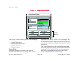
views. Figure 6 shows an example of the Interface
Device view for the Model 8H02-16. The views for
the Model 2E42-27 and Model 2E43-27 are
similar except for the number of Interface icons.
• Interface Device view
• Chassis Device view
• Physical Device view
Refer to Introduction for information on accessing
SPECTRUM views from the Device icon and
accessing device-specific subviews.
Interface Device View
This section describes the Interface icons and the
Interface Options panel displayed in the Interface
Device view. This view provides dynamic
configuration and performance information for
each interface on the device. If the configuration
changes, SPECTRUM modifies the Device view
after the next polling cycle to reflect the new
configuration. This view also provides a Device
icon that allows you to monitor the device
operation and to access other device-specific
Device Management
P a g e 19
SmartSwitch 2000
Device Views
Figure 6: Interface Device View
Primary Landscape of 8H02_16
File View
Help
Model
Network Address
System Up-Time
Contact
Manufacturer
Description
Device Type
Location
Primary Application
Serial Number
Bridging
Model Name
Filter
Network Information ADDRESS
Physical
Interface Description
8H02_16
Device Icon
1
ON
Interface Options Panel
5
ON
9
ON
13
ON
ETHERNET
ETHERNET
ETHERNET
ETHERNET
0:01D:17:2F:B6
0:01D:17:2F:BE
0:01D:17:2F:C2
0:01D:17:2F:CA
2
3
ON
6
0
ON
0
10 ON
14
0
ON
ETHERNET
ETHERNET
ETHERNET
ETHERNET
0:01D:17:2F:B7
0:01D:17:2F:BF
0:01D:17:2F:C3
0:01D:17:2F:CB
3
0
ON
7
0
ON
11
0
ON
15
0
ON
ETHERNET
ETHERNET
ETHERNET
ETHERNET
0:01D:17:2F:B8
0:01D:17:2F:BG
0:01D:17:2F:C4
0:01D:17:2F:CC
4
0
ON
8
0
ON
12
0
ON
16
0
ON
ETHERNET
ETHERNET
ETHERNET
ETHERNET
0:01D:17:2F:B9
0:01D:17:2F:BH
0:01D:17:2F:C5
0:01D:17:2F:CD
0
Device Management
0
0
Interface Icons
0
P a g e 20
SmartSwitch 2000
Device Views
Interface Icon
These icons represent the interfaces or ports of
the device. The icons identify the type of interface
or port (e.g., Ethernet) and provide statistical
Note:
Note:
information. Figure 7 shows an example of an
Interface icon, its Icon Subviews menu, and its
labels/double-click zones
The callouts (a through f) displayed in the illustration below identify the label and, if available,
the view to which it provides double-click zone access. For example, the icon area referred to by
callout (b) displays the administrative status and provides double-click access to the Port
Configuration - CSIIfPort view.
The menu displayed in the illustration is the Icon Subviews menu for that Interface icon.
Device Management
P a g e 21
SmartSwitch 2000
Device Views
Figure 7:
Interface Icon
(a)
(b)
Icon Subviews Menu
Close
Navigate
Alarms
Performance
Notes
Utilities
...
Configuration
Model Information
Ctrl +c
1
ON
ETHERNET
0:0:1D:F:FD:B6
3
(c)
(d)
(e)
(f)
a
Interface Label
e
b
Administrative Status Label/Port
Configuration-CSIIfPort View
Network Information Label/Network
Information Panel Dialog Box
f
Gauge Label/Performance - CSIIfPort View
c
Interface Type Label
d
MAC Address Label/CSI Interface Port
Model Information View
Device Management
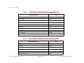
Interface Icon Subviews Menu
Table 1 describes the Interface icon devicespecific subviews menu selections. For
P a g e 22
SmartSwitch 2000
Device Views
information on accessing device-specific subviews
menus. See Introduction.
Table 1: Interface Icon Subviews Menu
Menu Selection
Description
Configuration
Opens the Device Configuration view described in
Configuration Views.
Model Information
Opens the Model Information view described in the
Operator’s Reference.
Interface Label
This label displays the interface (port) number.
Administrative Status Label
This label displays the status of this interface.
Double-click this label to open the Port
Configuration - CSIIfPort view described in
Configuration Views. Table 2 and Table 3 list the
possible states relative to the application selected
(Physical or Bridging). The default application for
this view is Physical (MIB-II). To select the
application to be displayed, click the Filter menu
button in the Interface Options panel. (Refer to
the Interface Options Panel description for more
information on the Filter menu button.)
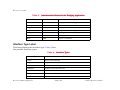
Table 2: Administrative Status for the Physical or MIB II Application
Color
Status
Description
Green
ON
Port is operational.
Blue
OFF
Port is off.
Yellow
TST
Port is in the test mode.
Device Management
P a g e 23
SmartSwitch 2000
Device Views
Table 3: Administrative Status for the Bridging Application
Color
Status
Description
Green
FWD
Bridge port is forwarding.
Blue
DIS
Port is disabled.
Magenta
LST
Bridge is in the listening mode.
Magenta
LRN
Bridge is in the learning mode
Orange
BLK
Bridge port is in the blocking mode.
Red
BRK
Bridge port is broken.
Blue
UNK
Status is unknown.
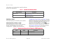
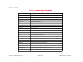
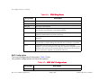
Interface Type Label
This label displays the interface type. Table 4 lists
the possible interface types.
Table 4:
Interface Types
Type
Description
Other
None of the following
Reg1822
Regular 1822
HDH1822
HDLC Distant Host protocol
DDNX25
Defense Data Network X.25
rfc877X25
RFC877 X.25
Ethernet
Ethernet CSMA/CD
iso88023
ISO CSMA/CD
Device Management
P a g e 24
SmartSwitch 2000
Device Views
Table 4:
Interface Types (Continued)
Type
Description
iso88024
ISO token bus
iso88025
ISO token ring
iso88026
ISO man
starLan
StarLAN IEEE 802.3
Prot10MB
ProNET 10 Mbps
Prot80MB
ProNET 80 Mbps
HyChan
Hyperchannel
FDDI
Fiber Distributed Data Interface
LAPB
X.25 Line Access Procedure, Balanced
SDLC
IBM Synchronous Data Link Control protocol
T1
T1 link (USA and Japan)
CEPT
T1 link (Europe)
BasicISDN
Basic Integrated Services Digital Network
PrimISDN
Proprietary Integrated Services Digital Network
PPSerial
Proprietary Point to Point Serial
PPP
Point to Point Protocol
SFTWARLPBK
Software Loopback
CLNPoverIP
Connectionless Network Protocol over IP
Enet3MB
Ethernet 3 Mbps
Device Management
P a g e 25
SmartSwitch 2000
Device Views
Table 4:
Interface Types (Continued)
Type
Description
XNSoverIP
Xerox Network Service Protocol over IP
SLIP
Generic Serial Line IP
ULTRA
ULTRA Technologies
T-3
T3 link
SMDS
Switched Multimegabit Data Service
FrameRelay
T1 Frame relay
MAC Address Label
This label displays the MAC address of the device
interface. Double-click this label to open the CSI
Interface Port Model Information View display
described in the Operator’s Reference.
Network Information Label
This label displays user-selectable network
information (Address, Name, or Mask). The
default is Address.
To change this label’s display, use the Interface
Options panel described later in this chapter, or
do the following:
1
Double-click the label to open the Network
Information Panel dialog box.
Device Management
2
Click the network information entry you wish
to display.
3
Click OK.
OK
Gauge Label
This label displays the performance statistic
determined by the Gauge Control Panel for this
interface. (Refer to the Gauge Control Panel
description for more information.) Double-click
this label to open the Performance - CSIIfPort
view described in the Operator’s Reference.
Interface Options Panel
This area of the Interface Device view (Figure 6)
allows you to modify the presentation of a
P a g e 26
SmartSwitch 2000
Device Views
highlighted icon. Double-click a non-text area of
this panel to open the Gauge Control Panel view
described later in this chapter. The Interface
Options panel provides the information described
below.
Filter
This menu button allows you to select the
application to be displayed by the Interface icons.
You can select other applications such as IP
routing if the SPECTRUM Routing Services
Management Module is loaded. For more
information, refer to the Routing Services
Management Module Guide.
label of the Interface icon. To access the Gauge
Control Panel view, double-click the background
of the Interface Options panel, or do the following:
1
Highlight the Interface Options panel.
2
From the View menu, select Icon Subviews ->
Gauge Control Panel.
Panel
Network Information
This menu button allows you to select the type of
information displayed in the Network Information
label of the highlighted icon. Possible selections
are ADDRESS, NAME, or MASK.
Interface Description
This field provides a description of the highlighted
interface. If no interface is highlighted, this field
is empty or shows the interface previously
highlighted.
Gauge Control Panel
This view (Figure 8) allows you to change the type
of statistical information displayed on the Gauge
Device Management
P a g e 27
SmartSwitch 2000
Device Views
Figure 8:
Gauge Control Panel
Gauge Control Panel
Selected Attribute
Gauge Mode
Load
Load In
Load Out
Packet Rate
In Packet Rate
Out Packet Rate
% Discard
% Filtered
Rates
Totals
Percentages
Numeric
Linear
Apply
Keep Settings
Reset
Close
Gauge
Buttons
Default
The Gauge Control Panel provides the following:
•
•
•
•
Gauge Mode area
Selected Attribute area
Gauge Type area
Gauge buttons
Gauge Mode
This area allows you to select the type of
information shown on the Gauge label of the
Device Management
Interface icon: Rates, Totals, or Percentages. The
Percentages selection displays the percentage of
the selected interface compared to the rest of the
interfaces.
The color displayed on the Gauge label depends
upon the particular mode and statistical attribute
selected. Table 5 and Table 6 list the attributes
and their corresponding colors for the Totals
mode and Rates mode, respectively.
P a g e 28
SmartSwitch 2000
Device Views
Table 5: Totals Mode: Attributes and Corresponding Color
Selected Attribute
Color
Errors
Orange
In Packets
Blue
Out Packets
Blue
In Octets
Green
Out Octets
Green
Discards
Tan
Forwarded
Purple
Host Bound
Yellow
Transmitted
White
Filtered
Gray
Table 6: Rates Mode: Attributes and Corresponding Color
Selected Attribute
Color
Load
Green
Load In
Green
Load Out
Green
Packet Rate
Blue
In Packet Rate
Blue
Out Packet Rate
Blue
Device Management
P a g e 29
SmartSwitch 2000
Device Views
Table 6: Rates Mode: Attributes and Corresponding Color
Selected Attribute
Color
% Discard
Tan
% Filtered
Gray
%Forwarded
Violet
%Host Bound
Yellow
%Error
Orange
%Transmitted
White
Selected Attribute
This area allows you to select the statistical
attribute displayed on the Interface icon’s Gauge
label. The label changes color to reflect the
attribute selected.
Gauge Type
This area allows you to select either a numeric or
linear display on the Gauge label.
Gauge Buttons
The following describes the Gauge buttons:
Apply
Applies the current settings to the Gauge label for
as long as the view is open.
Keep Settings
Saves the current settings while SpectroGRAPH is
running. Settings return to default when you
restart SpectroGRAPH.
Device Management
P a g e 30
SmartSwitch 2000
Device Views
Chassis Device View
Reset
Returns the settings to the previously saved
values.
Close
Closes the Gauge Control Panel view.
Default
Returns the settings to the SPECTRUM default.
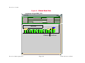
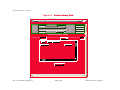
Chassis Device View
This view uses a Chassis Device icon to provide a
logical representation of the device chassis and its
interfaces or ports. The Chassis Device icon
provides menu and double-click zone access to
the views that monitor the interfaces.
Figure 9 shows an example of the Chassis Device
view for the 2E42-27R device.
Device Management
P a g e 31
SmartSwitch 2000
Device Views
Figure 9:
Chassis Device View
Landscape of type 2E42_27R
File View
Help?
Model Name
Network Address
System Up-Time
Contact
Manufacturer
Description
Device Type
Location
Primary Application
Bridging
Serial Number
2E42-27R
27 UNK
Bridging
FDDI 1.1
1 A CON 2 B CON
14 FWD 15 FWD 16 FWD 17FWD 18 FWD 19 FWD 20FWD 21 FWD 22FWD 23 FWD 24 FWD 25 FWD 26 FWD
1
FWD
2
FWD
3
FWD
4
FWD
5
FWD
6
FWD
7
FWD
8
FWD
9
FWD
10FWD 11FWD 12FWD 13 FWD
Chassis Device Icon
Device Management
P a g e 32
SmartSwitch 2000
Device Views
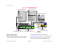
Chassis Device Icon
This icon is a logical representation of the
physical device and its front panel interfaces or
ports. This section describes the information
Note:
Note:
available from the Chassis Device icon. Figure 10
shows an example of the Chassis Device icon for
the 2E42-27R device.
The callouts displayed in this illustration identify the label name and the view to
which it provides double-click access. For example, Device Type Label/Device
Configuration View displays the device model number and provides double-click
access to the Device Configuration view.
The menus displayed in the illustration are the Icon Subviews menus for that label.
Device Management
P a g e 33
SmartSwitch 2000
Device Views
Figure 10:
Chassis Device Icon
Device Icon Subviews
Bridging Icon Subviews
Ctrl +c
Close
Navigate
Alarms
Performance
Notes...
Utilities
Configuration
Application Display
Model Information
Application View
Module Notes
Close
Ctrl +c
Navigate
Alarms
Performance
Notes...
Utilities
Bridge Performance
Bridge Detail
Bridge Model Information
Special Database
Spanning Tree Information
Static Database Table
Transparent Bridge Info
Interface Icon Subviews
Close
Navigate
Alarms
Performance
Notes...
Utilities
Configuration
Ctrl +c
Device Type Label/
Device Configuration View
2E42-27R
27 UNK
Bridging
1
FWD
FDDI 1.1
2
FWD
Application Label/
CSI Bridge Performance View
3
FWD
FWD
5
This label identifies the type of device. (Refer to
Figure 10.) Double-click this area to open the
A
CON
2
B
CON
FWD
Interface Labels/
Performance - CSIIfPort View
Device Type Label
Device Management
4
1
Logical Ports/
Port Configuration View
FDDI Label/
FDDI Views
Device Configuration view described in
Configuration Views.Device Icon Subviews Menu
Table 7 lists each of the device-specific Icon
Subviews menu selections available for this
P a g e 34
SmartSwitch 2000
Device Views
device. For information on accessing devicespecific subviews, see Introduction.
Table 7:
Device Icon Subviews Menu
Menu Selection
Description
Configuration
Opens the Device Configuration view described in
Configuration Views.
Application Display
Opens the Application menu selection. This menu selection
allows you to select the physical or bridging application.
Model Information
Opens the Model Information view described in the
Operator’s Reference.
Application View
Opens the Application view described in Application Views.
Module Notes
Opens the Module Notes dialog box.
Application Label
Bridging Icon Subviews Menu
This label provides access to the Bridging Icon
Subviews menu. (Refer to Figure 10.) Double-click
the Application label to open the CSI Bridging
Performance view described in the Operator’s
Reference.
Table 8 lists specific Icon Subviews menu
selections for the Application Label. For
information on accessing device-specific
subviews, see the Introduction section.
Table 8: Application Label Icon Subviews Menu
Menu Selection
Bridge Performance
Device Management
Description
Opens the Performance view described in the
Operator’s Reference.
P a g e 35
SmartSwitch 2000
Device Views
Table 8: Application Label Icon Subviews Menu
Bridge Detail
Opens the Detail view described in the Operator’s
Reference.
Bridge Model Information
Opens the Model Information view described in the
Operator’s Reference.
Special Database
Opens the Special Database view.
Spanning Tree Information
Opens the Spanning Tree Information view described
in the Application Views section.
Static Database Table
Opens the Static Database Table view described in the
Application Views section.
Transparent Bridge Info
Opens the Transparent Bridge Information view, with
Forwarding Database and Port Tables described in the
Application Views section.
Interface Labels
These labels identify the number and activity
status of each port. (Refer to Figure 10.) Table 9
and Table 10 list the possible states relative to the
application selected. Double-click the label to
open the Performance - CSIIfPort view described
in the Operator’s Reference.
Table 9: Interface Status for the Bridging Application
Color
Status
Description
Green
FWD
Bridge port is forwarding.
Blue
DIS
Port is disabled.
Magenta
LST
Bridge is in the listening mode.
Magenta
LRN
Bridge is in the learning mode
Device Management
P a g e 36
SmartSwitch 2000
Device Views
Table 9: Interface Status for the Bridging Application
Color
Status
Description
Orange
BLK
Bridge port is in the blocking mode.
Red
BRK
Bridge port is broken.
Blue
UNK
The status is unknown.
Table 10: Interface Status for the Physical (MIB II) Application
Color
Status
Description
Green
ON
Port is operational.
Blue
OFF
Port is off.
Yellow
TST
Port is in the test mode.
this label to open the FDDI Application views
described in the Operator’s Reference.
Interface Icon Subviews Menu
This menu’s Configuration option opens the
Configuration dialog box, which allows you to
enable or disable the selected port. For
information on accessing device-specific
subviews, see the Introduction.
FDDI Icon Subviews Menu
Table 11 describes each of the Icon Subviews
menu selections available for FDDI. For
FDDI Label
This label provides access to the FDDI Icon
Subviews menu. (Refer to Figure 10.) Double-click
Device Management
P a g e 37
SmartSwitch 2000
Device Views
information on accessing device-specific
subviews, see the Introduction section..
Table 11: FDDI Label Icon Subviews Menu
Menu Selection
Description
FDDI Performance
Opens the FDDI Performance view. (Not available
for FddiNoMAC).
FDDI
Configuration
Opens the FDDI Configuration view.
FDDI Station List
Opens the FDDI Station List view. (Not available
for FddiNoMAC).
FDDI Model
Information
Opens the Model Information view for FDDI.
Logical Ports Labels
Logical Ports Icon Subviews Menu
These labels provide access to the Logical Port
Icon Subviews menu. Double-click a label to open
the Port Configuration View.
Table 12 describes each of the Icon Subviews
menu selections. For information on accessing
device-specific subviews, see the Introduction
section.
Table 12:
Logical Ports Icon Subviews Menu
Menu Selection
Description
Port Notes
Opens the Port Notes facility.
Enable/Disable Port
Enables or disables the selected port.
Port Configuration View
Opens the Port Configuration view.
Device Management
P a g e 38
SmartSwitch 2000
Device Views
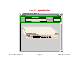
Physical Device View
Physical Device View
This view provides a static image of the device and
its ports or interfaces and does not change to
reflect configuration status. Figure 11 is an
example of the Physical Device view for the 8H0216 device.
Device Management
P a g e 39
SmartSwitch 2000
Device Views
Figure 11:
Physical Device View
Landscape of type 8H02_16
Help
File View
Model Name
Network Address
System Up-Time
Contact
Manufacturer
Description
Device Type
Location
Primary Application
Bridging
Serial Number
Smart
SWITCH
SmartSwitch 10/100
WITH SecureFast
8H02-16
Device Management
Reset
Virtual Networking
PWR
OPR
COM
1X 2X 3X 4X 5X 6X
7X 8X 9X 10X 11X12X 13X14X
P a g e 40
15
16
SmartSwitch 2000
Configuration Views
What Is in This Section
Configuration Views
This section describes the Configuration views available for the SmartSwitch Modules. These views display
network configuration and operating information for the device and its interfaces.
What Is in This Section
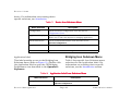
Device Configuration Information
The following Configuration views are available for
this device:
This section of the Configuration view displays
the following device-specific information.
• Device Configuration
• Port Configuration - CSIIfPort
• FddiMAC Device Configuration
• Port Configuration
Refer to the Introduction section for information
on Accessing SPECTRUM Views from the Device
Icon and Accessing Device-Specific Subviews.
Contact Status
Indicates whether a connection with the device
has been established.
Device Configuration View
Opens the Community Name window, which
provides information on the SmartSwitch Module
components.
This view also provides the following SPMA view
buttons that allow you to configure this device.
Refer to the SPECTRUM Portable Management
Application Tools Guide for details on the views
accessible from these buttons.
This view provides device -specific configuration
information as well as access to other views that
allow you to configure device components.
Device Management
P a g e 41
SmartSwitch 2000
Configuration Views
Download Application
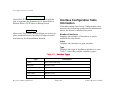
Interface Configuration Table
Information
Opens the TFTP Download View, which enables
you to upgrade the firmware for a SmartSwitch
Module from a TFTP Boot or Bootp Server.
This table within the Device Configuration view
provides the following configuration information
about the device’s interfaces or ports.
Trap Table
Opens the Trap Table, which allows you to set up
your workstation to be notified of traps received
and sent by the SmartSwitch Module.
Number of Interfaces
Displays the number of interfaces or ports
available for this device.
Index
Displays the interface or port number.
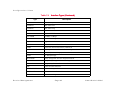
Type
Displays the type of hardware interface or port.
Table 13 lists the possible interface types.
Table 13:
Interface Types
Type
Description
Other
None of the following
Reg1822
Regular 1822
HDH1822
HDLC Distant Host protocol
DDNX25
Defense Data Network X.25
rfc877X25
RFC877 X.25
Ethernet
Ethernet CSMA/CD
Device Management
P a g e 42
SmartSwitch 2000
Configuration Views
Table 13:
Interface Types (Continued)
Type
Description
iso88023
ISO CSMA/CD
iso88024
ISO token bus
iso88025
ISO token ring
iso88026
ISO man
starLan
StarLAN IEEE 802.3
Prot10MB
ProNET 10 Mbps
Prot80MB
ProNET 80 Mbps
HyChan
Hyperchannel
FDDI
Fiber Distributed Data Interface
LAPB
X.25 Line Access Procedure, Balanced
SDLC
IBM Synchronous Data Link Control protocol
T1
T1 link (USA and Japan)
CEPT
T1 link (Europe)
BasicISDN
Basic Integrated Services Digital Network
PrimISDN
Proprietary Integrated Services Digital Network
PPSerial
Proprietary Point to Point Serial
PPP
Point to Point Protocol
SFTWARLPBK
Software Loopback
CLNPoverIP
Connectionless Network Protocol over IP
Enet3MB
Ethernet 3 Mbps
Device Management
P a g e 43
SmartSwitch 2000
Configuration Views
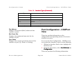
Port Configuration - CSIIfPort View
Table 13: Interface Types (Continued)
Type
Description
XNSoverIP
Xerox Network Service Protocol over IP
SLIP
Generic Serial Line IP
ULTRA
ULTRA Technologies
T-3
T3 link
SMDS
Switched Multimegabit Data Service
FrameRelay
T1 Frame relay
Phy Address
Displays the physical (MAC) address of the
interface or port.
Max Frame Size
Displays the maximum frame size for the
interface or port.
Oper Status
Displays the current operational state of this
interface or port (Up, Down, or Testing).
Port Configuration - CSIIfPort
View
This view provides information on the
configuration and operating status of the device
interfaces or ports.
To access the Port Configuration - CSIIfPort view
for a particular interface or port, do the following:
1
Within the Interface Device view, highlight the
Interface icon.
2
From the View menu, select Icon Subviews ->
Configuration.
Configuration
This view provides the following information:
Device Management
P a g e 44
SmartSwitch 2000
Configuration Views
FddiMAC Device Configuration View
Interface Index
Displays the numerical value identifying the
interface or port.
2
Interface Type
Displays the type of interface or port.
Operation Status
Displays the current operating status of the
interface or port. Possible values are On, Off, and
Test.
Admin Status
Displays the current administrative status of the
interface or port. Possible values are On, Off, and
Test.
From the View menu, select Icon Subviews ->
Configuration or click the applicable mouse
button (middle or right) and select
Configuration.
Configuration
Station Configuration
This section of the FddiMAC Device Configuration
view provides the following configuration
information on the FDDI station.
Ring State
The current state of the FDDI Ring. Table 14 lists
the possible states and their descriptions.
IF Description
Provides a description of the interface or port.
FddiMAC Device
Configuration View
The FddiMAC Device Configuration view provides
configuration and operating status information.
To access this view, do the following:
1
Highlight the FddiMAC icon in the Application
view (Icon mode) or the FddiMAC text label
(List mode).
Device Management
P a g e 45
SmartSwitch 2000
Configuration Views
Table 14:
FDDI Ring States
Ring States
Description
Isolated
The concentrator is not attached to the ring.
Non-Op
The concentrator is attempting to enter the ring.
Ring-Op
The ring is operational.
Detect
The claim/beacon process of the FDDI ring protocol has exceeded
one second. This indicates a potential problem.
Non-Op-Dup
The ring failed to complete the claim/beacon process because a
duplicate FDDI address has been detected.
Ring-Op-Dup
The ring is operational, but a duplicate FDDI address has been
detected.
Directed
The claim/beacon process did not complete within nine seconds. The
concentrator is now sending directed beacons to indicate a problem.
Trace
A problem has been detected with the station or its upstream
neighbor. A trace is being sent to notify the upstream neighbor of the
problem. The concentrator and all stations between the concentrator
and its upstream neighbor can perform self-tests.
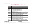
MAC Configuration
The actual configuration of the station. Table 15 lists
the possible configurations and their descriptions.
Table 15:
Ring States
Isolated
Device Management
SMT MAC Configurations
Description
The path is not inserted into any path.
P a g e 46
SmartSwitch 2000
Configuration Views
Table 15: SMT MAC Configurations (Continued)
Local_A
The A port is inserted into a local path and the B port is not.
Local_B
The B port is inserted into a local path and the A port is not.
Local_AB
Both A and B are inserted into a local path.
Local_S
The S port is inserted into a local path.
Wrap_A
The secondary path is wrapped to the A port.
Wrap_B
The secondary path is wrapped to the B port.
Wrap_AB
The primary path is wrapped to the B port and the secondary path is
wrapped to the A port.
Wrap_S
The primary port is wrapped to the S port.
C_Wrap_A
The primary and secondary paths are joined internally in the station
and wrapped to the A port. Regarding token flow, all resources on the
secondary path precede those of the primary path.
C_Wrap_B
The primary and secondary paths are joined internally in the station
and wrapped to the B port. Regarding token flow, all resources on the
secondary path precede those of the primary path.
C_Wrap_S
The primary and secondary paths are joined internally in the station
and wrapped to the S port. Regarding token flow, all resources on the
secondary path precede those of the primary path.
Thru
The primary path enters the A port and emerges from the B port. The
secondary path enters the B port and emerges from the A port.
Current MAC Path
The ring that this station resides on. Possible
entries are Primary, Secondary, or Local.
Device Management
MAC Address
The MAC (physical) address of this station.
P a g e 47
SmartSwitch 2000
Configuration Views
Port Configuration View
MAC Count
The number of MACs supported by this station.
The number of non-master ports on this station.
TVX (milli sec)
The valid transmission time, in milliseconds.
Master Ports
The number of master ports on this station.
Port Configuration View
SMT Information
This section of the FddiMAC Device Configuration
view provides the following configuration
information on the FDDI SMT:
SMT Version
The version of Station Management (SMT)
running.
OBS Present
Indicates whether an Optical Bypass Switch
(OBS) is connected.
T-Notify (sec)
The timer value, in seconds, used in Neighbor
Notification Protocol. The allowed range is from 2
to 30 seconds.
T-Req (milli sec)
The Target Token Rotation Time (TTRT) bid, in
milliseconds, made by this concentrator.
Device Management
T-Neg (milli sec)
The winning TTRT bid, in milliseconds, on the
ring.
The Port Configuration view provides information
on the configuration and operating status of the
ports. To access this view, do the following:
1
Highlight the Logical Port icon in the Chassis
Device view.
2
From the View menu, select Icon Subviews ->
Port Configuration View.
View
The Port Management section of the FDDI Port
Configuration view provides the following
information:
Port Action
Allows you to enable/disable the port. The state
returns to “Other” once the port has been
Enabled/Disabled.
Port State
The status of this port. Possible states are
disabled, connecting, standby, and active.
P a g e 48
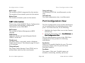
SmartSwitch 2000
Configuration Views
port is connected and every 10 seconds thereafter.
It ranges from 10-4 to 10-15 and is reported as a
whole integer. For example, if the port’s link error
rate estimate is computed to be 10-5, the value
reported in this field would be 5, which represents
an actual rate of 1,250 bit errors per second. A
lower link error rate estimate indicates a higher
bit error rate as shown in Figure 12.
Port Type
The type of port. Possible port types are A_Port,
B_Port, Slave, or Master.
Link Error Rate Estimate
The link error rate estimate is a cumulative longterm average of the bit error rate, which
represents the quality of the physical link. The
link error rate estimate is computed when the
Figure 12:
Bit
Errors
per
Second
Link Error Rate Estimate
000000125.
.00000125
.0000125
.000125
.00125
.0125
.125
1.25
12.5
125
1250
12500
4
5
6
7
8
9 10 11 12 13 14 15
Reported Link Error Rate Estimate (n)
Device Management
P a g e 49
SmartSwitch 2000
Configuration Views
Link Error Monitor Count
The aggregate link error monitor count. This
count is set to zero on station power up and
increments each time the port’s link error monitor
detects an error. An increasing link error monitor
count usually indicates a problem with the
connectors or the cable between this port and the
node.
Link Error Rate Cutoff
The link error rate threshold at which a link
connection is flagged as faulty and the port
disabled by SMT. The default link error rate cutoff
threshold is 7, which represents 12.5 bit errors
per second.
Link Error Rate Alarm
The link error rate threshold above which an
alarm for the port will be generated. The default
link error rate alarm threshold is 8, which
represents 1.25 bit errors per second.
Link Error Monitor Reject Count
The link error monitor count of the times the link
has been rejected.
Device Management
P a g e 50
SmartSwitch 2000
Event and Alarm Messages
Device Events and Alarms
Event and Alarm Messages
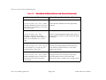
This chapter lists the types of events and alarms generated by the SmartSwitch Modules and provides any
probable cause messages corresponding to these alarms.
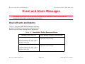
Device Events and Alarms
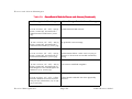
Table 16 lists the SPECTRUM database directory
paths (in bold) and the messages displayed for the
Event Log and Alarm Manager when applicable.
Table 16: SmartSwitch Module Events and Alarms
Message in the Event Log
Alarm Manager Probable Cause Message
CsEvFormat/Event00010306
No probable cause message
{d “%w- %d %m-, %Y - %T”} - A(n) {t}
device, named {m}, has been cold
started. (event [{e}])
CsEvFormat/Event00010307
No probable cause message
{d “%w- %d %m-, %Y - %T”} - A(n) {t}
device, named {m} has been warm
started, (event [{e}])
Device Management
P a g e 51
SmartSwitch 2000
Event and Alarm Messages
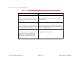
Table 16: SmartSwitch Module Events and Alarms (Continued)
Message in the Event Log
Alarm Manager Probable Cause Message
CsEvFormat/Event00010308
CsPCause/Prob00010308
{d “%w- %d %m-, %Y - %T”} - A(n) {t}
device, named {m}, has detected a
communication Link Down. (event
[{e}])
Communication link is down.
CsEvFormat/Event00010309
{d “%w- %d %m-, %Y - %T”} - A(n) {t}
device, named {m}, has detected a
communication Link Up. (event [{e}])
No probable cause message
CsEvFormat/Event0001030a
CsPCause/Prob0001030a
{d “%w- %d %m-, %Y - %T”} - A(n) {t}
device, named {m}, has detected an
Authentication Failure. (event [{e}])
Authorization failure. Other user is trying to
connect to device with an invalid community
string.
CsEvFormat/Event0001030b
CsEvFormat/Event0001030
CsPCause/Prob0001030b
{d “%w- %d %m-, %Y - %T”} - A(n) {t}
device, named {m}, has detected an
EGP Neighbor Loss. EGP Neighbor IP
address is {0 1}. (event [{e}])
Lost contact with EGP neighbor.
CsEvFormat/Event000d01a0
CsPCause/Prob000d01a0
{d “%w- %d %m-, %Y - %T”} - A Port
Interface Module has been inserted
into port {I 3} of interface {I 1} on {m}
({t}). (event [{e}]).
A Port Interface Module has been physically
inserted.
Device Management
P a g e 52
SmartSwitch 2000
Event and Alarm Messages
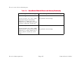
Table 16: SmartSwitch Module Events and Alarms (Continued)
Message in the Event Log
Alarm Manager Probable Cause Message
CsEvFormat/Event000d01a1
CsPCause/Prob000d01a1
{d “%w- %d %m-, %Y - %T”} - A Port
Interface Module has been removed
from port {I 3} of interface {I 1} on {m}
({t}). (event [{e}])
A Port Interface Module has been physically
removed.
CsEvFormat/Event000d01a2
CsPCause/Prob000d01a2
{d “%w- %d %m-, %Y - %T”} Network configuration change
reported by {m} ({t}). Device linked to
port {I 3} on interface {I 1}. (event
[{e}])
A device supporting link integrity, fiber optic or
twisted pair, has made a valid connection (link)
to this port.
CsEvFormat/Event000d01a3
CsPCause/Prob000d01a3
{d “%w- %d %m-, %Y - %T”} - Port {I
3} on interface {I 1} of {m} ({t}), has
unsegmented. (event [{e}]).
A device previously linked with this port has
been removed, powered down, or the cable
segment has a fault.
CsEvFormat/Event000d0351
CsPCause/Prob000d0351
CsPCause/Prob000d035
{d “%w- %d %m-, %Y - %T”} - Front
panel redundant port {I 1} has been
activated by device {m} of type {t}.
(event [{e}])
A new port has been activated for the front
panel redundant circuit. This does NOT
indicate this port is usable, but is being tested.
Device Management
P a g e 53
SmartSwitch 2000
Event and Alarm Messages
Table 16: SmartSwitch Module Events and Alarms (Continued)
Message in the Event Log
Alarm Manager Probable Cause Message
CsEvFormat/Event000d0001
CsPCause/Prob000d0001
{d “%w- %d %m-, %Y - %T”} - {m} of
type {t} has reported a root change.
(event [{e}])
This bridge has become the new root of the
Spanning Tree.
CsEvFormat/Event000d0002
CsPCause/Prob000d0002
{d “%w- %d %m-, %Y - %T”} - Bridge
{m} of type (t) has reported a network
topology change (event [{e}]).
A port has transitioned from the Learning state
to the Forwarding state, or from the Forwarding
state to the Blocking state.
CsEvFormat/Event00830000
{d “%w- %d %m-, %Y - %T”} - DLM
LostContact trap for Destination
Address {0 1}, Owner Address {0 2}
from {t} device, named {m}. (event
[{e}]).
Device Management
No probable cause message
P a g e 54
SmartSwitch 2000
Event and Alarm Messages
Table 16: SmartSwitch Module Events and Alarms (Continued)
Message in the Event Log
Alarm Manager Probable Cause Message
CsEvFormat/Event00830001
CsEvFormat/Event0083000
{d “%w- %d %m-, %Y - %T”} - DLM
Threshold Trap for Destination
Address {0 1}, Owner {0 2}, OID
sequence {I 3}, OID Object {0 4} from
{t} device, named {m}. (event [{e}]).
No probable cause message
CsEvFormat/Event00830002
{d “%w- %d %m-, %Y - %T”} - DLM
ReestabContact Trap for Destination
Address {0 1}, Owner Address {0 2}
from {t} device, named {m}. (event
[{e}])}.
Device Management
No probable cause message
P a g e 55
SmartSwitch 2000
Application Views
What Is in This Section
Application Views
What Is in This Section
This section describes the device-specific
applications listed below for the SmartSwitch
Modules. The corresponding application model
type is shown in parentheses.
•
•
•
•
•
Interface Remap (CtIfRemapApp)
Fast Ethernet (FastEnetApp)
FDDI FNB Application (FddiMAC)
ATM Application (ATM_Client)
DownLoad App (CtDownLoadApp)
Common Applications Not
Covered Here
This device supports the following common
applications described in the Application View
Reference:
• Bridging (CSIBridge)
- Spanning Tree (Ct_Stp_App)
- Static (Static_App)
- Transparent (CT_Tp_Appl)
Device Management
• MIB-II (SNMP2_Agent)
- ICMP (ICMP_App)
- IP (IP2_App)
- System (System2_App)
- UDP (UDP2_App)
• RS-232 App (RFC1317App)
The following major application is available if you
purchase the associated SPECTRUM product. The
application is described within the documentation
supplied with the product.
• Standard RMON (RMON App)
- Ethernet Probe 1(RMONEthProbe) through
Ethernet Probe 16 (RMONEthProbe)
Device Application View
This view shows the common and device-specific
applications supported by this device and
provides access to application-specific
information.
Refer to Device Views for more information.
Figure 13 shows an example of an Application
P a g e 56
SmartSwitch 2000
Application Views
view in the Icon mode. Figure 14 shows an
example of an Application view in the List mode.
To change the display mode, from the View menu
select Mode -> List or Icon.
Icon
Device Management
P a g e 57
SmartSwitch 2000
Application Views
Figure 13: Device Application View (Icon Mode)
Landscape of type 2E42_27R
Help
File View
Model Name
Network Address
System Up-Time
Contact
Manufacturer
Description
Location
Device Type
Bridging
Primary Application
Serial Number
Model Name
2E42_27R
Bridging
Fddi 1.1
FddiMAC
CSI Bridge
Fddi_MAC
Spanning Tree
MIB_II
SNMP2_agent
SNMP2_age
ICMP
ICMP_app
CT_stp_app
ICMP_app
Static
IP
IP2_app
Static_app
IP2_app
Transparent
SYSTEM
System2_app
CT_Tp_app
Device Management
System2_app
P a g e 58
SmartSwitch 2000
Application Views
Figure 14: Device Application View (List Mode)
Landscape of type 2E42_27R
File View
Help
Network Address
Model Name
System Up-Time
Contact
Manufacturer
Description
Location
Device Type
Primary Application
Bridging
Serial Number
SS8H
CSIBridge
CT_Stp_App
Static_App
CT_Tp_Appl
FddiMAC
SNMP2_Agent
ICMP_App
IP2_App
System2_App
UDP2_App
CtIfRemapApp
CtDownLoadApp
FastEnetApp
Device Management
P a g e 59
SmartSwitch 2000
Application Views
Interface Remap Application
Interface Remap Application
The name of the model type used to model the
application is CtIfRemapApp. The application
provides the ability to map one or more interfaces
to another interface. A map is defined by creating
a row in the Interface Remap Table (described
below) to specify the source and destination
interfaces. When a source interface is remapped
to a destination interface, the destination
interface transmits all packets received or
transmitted on the source interface. Counters on
the destination interface increment for all packets
transmitted by normal bridging or due to the
interface remap. Figure 15 shows a view of the
Interface Remap Table.
Access the Interface Remap Table as follows:
1
2
From the View menu, select Icon Subviews ->
Port Remap.
Remap
The Interface Remap Table provides the following
information:
Device Management
Max Number Entries
The maximum number of entries allowed in the
Interface Remap Table.
Sort
Used to sort the Interface Remap Table.
Find
Used to search the Interface Remap Table for a
specific interface.
Update
Highlight the CtIfRemapApp icon (Icon mode)
or text label (List mode).
Number Entries
The number of active entries in the Interface
Remap Table.
Physical Errors Enable
Physical error remapping can be Enabled,
Disabled, or Unsupported. Unsupported indicates
that the device is incapable of remapping physical
errors.
Used to update the Interface Remap Table.
Source Port
The source interface that will have packets
redirected to the destination interface as defined
by Destination.
Destination
Destination
The interface that will see all packets redirected
from Source Port.
Port
P a g e 60
SmartSwitch 2000
Application Views
Port Redirect
This button opens the Port Redirect view, where
you can add or delete an entry from the table.
Device Management
P a g e 61
SmartSwitch 2000
Application Views
Figure 15:
Interface Remap Table
Landscape of type 2E42_27R
File View
Help
Network Address
Model Name
System Up-Time
Contact
Manufacturer
Description
Device Type
Location
Primary Application
Serial Number
Bridging
Interface Remap Table
Number Entries
Physical Errors Enable
Sort
Find
Enable
Max Number Entries
Update
Source Port
Destination
Port Redirect
Device Management
P a g e 62
SmartSwitch 2000
Application Views
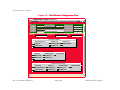
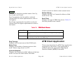
Fast Ethernet Application
Fast Ethernet Application
The name of the model type used to model the
application is FastEnetApp. The application
provides the Fast Ethernet Port Table and Fast
Ethernet Configuration view, which allow you to
configure ports for Ethernet or Fast Ethernet
transmission or use Auto-Negotiation to
determine transmission mode.
Fast Ethernet Port Table
Access this table as follows:
1
Highlight the FastEnetApp icon (Icon mode) or
text label (List mode).
2
From the View menu, select Icon Subviews ->
Control Table.
Table
Port
The physical port number to which this Fast
Ethernet information applies.
Operational Mode
The current operational mode of this port.
Fast Ethernet Configuration View
This view (Figure 16) allows you to configure ports
for Ethernet or Fast Ethernet transmission or to
use Auto-Negotiation in determining transmission
mode. Open this view by double-clicking any
entry in the Fast Ethernet Port Table. The Fast
Ethernet Configuration view carries the Interface,
Port Group, and Port information over from the
Port Table.
The Fast Ethernet Port Table provides the
following information:
Interface
The interface number to which this Fast Ethernet
information applies.
Port Group
The port group number to which this Fast
Ethernet information applies.
Device Management
P a g e 63
SmartSwitch 2000
Application Views
Figure 16:
Fast Ethernet Configuration View
Landscape of type 2E42_27R
File View
Model Name
Help
Network Address
System Up-Time
Contact
Manufacturer
Description
Device Type
Location
Serial Number
Primary Application
Bridging
Port Group
Interface
Port
Operational Mode
Auto-Negotiation
100BaseTX
100BaseFX
10BaseT
100BaseTXFD
100BaseFXFD
10BaseTFD
100BaseT4
Advertised Ability
10BaseT
100BaseTXFD
10BaseTFD
100BaseT4
100BaseTX
100BaseFX
100BaseFXFD
Received Technology
Undefined
Auto-Negotiation
Not-Detected
Device Management
10BaseT
10BaseTFD
100BaseTX
100BaseTXFD
100BaseT4
100BaseFX
P a g e 64
100BaseFXFD
SmartSwitch 2000
Application Views
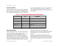
Operational Mode
These selections indicate the current operational
mode of this port. If you select Auto-Negotiation,
you can select as many modes as needed from the
Advertised Ability selections. You can only select
one Operational Mode: either Auto-Negotiation or
one of the specific modes. Table 17 lists the
current operational modes, their values, and their
descriptions.
Table 17: Current Operational Mode Values and Descriptions
Operational Mode
Value
Description
Auto-Negotiation
2
Auto-Negotiation/Parallel Detection
10Base-T
8
10Base-T
10Base-TFD
16
Full Duplex 10Base-T
100Base-TX
32
100Base-TX
100Base-TXFD
64
Full Duplex 100Base-TX
100Base-T4
128
100Base-T4
100Base-FX
256
100Base-FX
100Base-FXFD
512
Full Duplex 100Base-FX
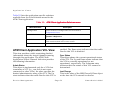
Advertised Ability
These selections indicate the advertised ability of
the local hardware. They become active on ports
that have Auto-Negotiation enabled. AutoNegotiation allows the FE-100TX RJ-45 port to
self-configure to 10 or 100 Mbps depending on
the speed of the attached device. The interfaces
can also dynamically configure themselves for full
duplex or half duplex (standard mode) operation
Device Management
when both ends of the link support AutoNegotiation. When only one link partner supports
Auto-Negotiation, the mode defaults to half
duplex.
Both local and remote management for the
SmartSwitch Module provide the ability to disable
Auto-Negotiation if desired. A port that does not
support Auto-Negotiation will be read as “other”
(1).
P a g e 65
SmartSwitch 2000
Application Views
Table 18 lists the Advertised Ability modes, their
values, and their descriptions.
Table 18: Advertised Ability Mode Values and Descriptions
Advertised Ability
Value
Description
10Base-T
8
10Base-T
10Base-TFD
16
Full Duplex 10Base-T
100Base-TX
32
100Base-TX
100Base-TXFD
64
Full Duplex 100Base-TX
100Base-T4
128
100Base-T4
100Base-FX
256
100Base-FX
100Base-FXFD
512
Full Duplex 100Base-FX
Received Technology
These selections indicate the advertised ability of
the remote hardware or link partner. These modes
are read-only. Table 19 lists the Received
Technology modes, their values, and their
descriptions.
Table 19: Received Technology Mode Values and Descriptions
Received
Technology
Value
Description
Undefined
1
Undefined
Auto-Negotiation
2
Auto-Negotiation/Parallel Detection
Not-Detected
4
Link Partner does not support AutoNegotiation
Device Management
P a g e 66
SmartSwitch 2000
Application Views
FDDI FNB Application
Table 19: Received Technology Mode Values and Descriptions
Received
Technology
Value
Description
10Base-T
8
10Base-T
10Base-TFD
16
Full Duplex 10Base-T
100Base-TX
32
100Base-TX
100Base-TXFD
64
Full Duplex 100Base-TX
100Base-T4
128
100Base-T4
100Base-FX
256
100Base-FX
100Base-FXFD
512
Full Duplex 100Base-FX
FDDI FNB Application
This application is available when the appropriate
High Speed Interface Module (HSIM) is installed.
This section describes the FDDI FNB application
supported by this device. The name of the model
type used to model the application is FddiMAC.
Table 20 lists the application-specific subviews
available from the Icon Subviews menu for the
FDDI FNB application.
Table 20: FDDI FNB Application Subviews menu
Menu Selection
Description
DevTop
Opens the Device Topology view described in the Operator’s
Reference.
Station List
Opens the FDDI Station List view described below.
Acknowledge
Allows you to acknowledge an alarm condition.
Device Management
P a g e 67
SmartSwitch 2000
Application Views
Table 20: FDDI FNB Application Subviews menu
Configuration
Opens the Device Configuration view described in Configuration
Views.
Model Information
Opens the Model Information view described in the Operator’s
Reference.
FDDI Station List View
This view displays information about the devices
connected to the FDDI ring and provides the
following functionality and information.
Clear Filter returns the Station table to its normal
state.
Update
This button updates the contents of the Station
Table.
MAC/Canonical
This button controls which type of address is
shown in the Station List. It toggles between MAC
(Physical) and Canonical (Ethernet) and displays
the format not currently selected.
Set Filter/Clear Filter
Set Filter Opens the Filter Dialog box for the
selected column of the Station table. Type a
character string to search the column.
Device Management
P a g e 68
SmartSwitch 2000
Application Views
ATM Client Application
Unsort returns the fields to their normal state.
Sort Up
Station Address
Displays the MAC or Canonical address of this
node on the ring.
This button has three possible states: Sort Up,
Sort Down, and Unsort.
Sort Up organizes the list within a selected
column from the lowest alphanumeric value to
the highest.
Node Class
Displays the type of FDDI ring device. Table 21
lists the possible node classes.
Sort Down organizes the list within a selected
column from the highest alphanumeric value to
the lowest.
Table 21:
FDDI Node Classes
Node Class
Description
Station
An FDDI node capable of receiving, transmitting, and repeating
data.
Concentrator
An FDDI node that provides attachment points for stations that are
not directly connected to the FDDI ring.
Ring Topology
Displays the current state of this FDDI node.
ATM Client Application
Master Ports
Displays the number of master ports on this
node. Values range from 0 to 255.
This section describes the ATM Client application
supported by this device. This application is
available when the appropriate High Speed
Interface Module (HSIM) is installed.
Upstream Neighbor
Displays the canonical or MAC address of the last
node to receive the token before this node.
Device Management
P a g e 69
SmartSwitch 2000
Application Views
Table 22 lists the application-specific subviews
available from the Icon Subviews menu for the
ATM Client application:
Table 22: ATM Client Application Subviews menu
Menu Selection
Description
Configuration
Opens the Device Configuration view described in
Configuration Views.
Model Information
Opens the Model Information view described in the
Operator’s Reference.
VCL Table
Opens the ATM Client Application VCL (Virtual Channel Link)
Table view described later in this section.
Interfaces
Opens the Interfaces view described later in this section.
ATM Client Application VCL View
enabled. The Down state indicates that the traffic
flow for this VCL is disabled.
This view provides a table containing detailed
information about the virtual channels passing
through this application. The ATM Client
Application Virtual Channel Link view provides
the following information.
Admin Status
This object is implemented only for a VCL that
terminates a VCC (i.e., one that is not crossconnected to other VCLs). Its value specifies the
desired administrative state of the VCL. The Up
state indicates that the traffic flow for this VCL is
Device Management
Oper Status
This object shows the current operational status
of the VCL. The Up and Down states indicate that
the VCL is currently operational or not
operational, respectively. The Unknown state
indicates that the status of this VCL cannot be
determined.
Last Change
This is the value of the MIB II’s sysUpTime object
at the time the VCL entered its current
P a g e 70
SmartSwitch 2000
Application Views
operational state. If the current state was entered
prior to the last re-initialization of the agent, then
this object contains a zero value.
of this VCC. An instance of this object only exists
when the local VCL endpoint is also the VCC
endpoint and the AAL5 is in use.
RTD (Receive Traffic Description) Index
The value of this object identifies the row in the
ATM Traffic Descriptor Table that applies to the
receive direction of this VCL.
Encaps Type
This is the type of data encapsulation used over
the AAL5 SSCS layer. An instance of this object
only exists when the local VCL endpoint is also
the VCC endpoint and the AAL5 is in use. The
definitions reference RFC 1483 Multiprotocol
Encapsulation over ATM AAL5 and to the ATM
Forum LAN Emulation specification.
TTD (Transmit Traffic Description) Index
The value of this object identifies the row of the
ATM Traffic Descriptor Table that applies to the
transmit direction of this VCL.
AAL (ATM Adaptation Layer) Type
An instance of this object only exists when the
local VCL endpoint is also the VCC endpoint and
the AAL is in use. The type of AAL used on this
VCC includes AAL1, AAL3/4, and AAL5. “Other”
indicates a user-defined AAL type. “Unknown”
indicates that the AAL type cannot be determined.
Transmit Size
This is the maximum AAL5 CPCS SDU size, in
octets, that is supported on the transmit direction
of this VCC. An instance of this object only exists
when the local VCL endpoint is also the VCC
endpoint and the AAL5 is in use.
Receive Size
This is the maximum AAL5 CPCS SDU size, in
octets, that is supported on the receive direction
Device Management
This object is implemented only for a VCL that is
cross-connected to other VCLs that belong to the
same VCC. All such associated VCLs have the
same value for this object, and all their crossconnections are identified by entries in the Cross
Connect Table for which VCL CC Id has the same
value. The value of this object is initialized by the
Row Status agent after the associated entries in
the Cross Connect Table have been created.
This object is used to create, delete, or modify a
row in this table. To create a new VCL, this object
is initially set to “createAndWait” or
“createAndGo.” This object must not be set to
“active” unless the following columnar objects
exist in this row:
• RTD Index
• XTD Index
P a g e 71
SmartSwitch 2000
Application Views
• AAL Type (if the local VCL endpoint is also the
VCC endpoint)
• Transmit Size (for AAL5 connections only)
• Receive Size (for AAL5 connections only)
• Encaps Type (for AAL5 connections only)
Note:
Note:
The Community Name field in the
Communication Information Panel of
the Model Information view must be
set to “private” in order to change
the fields in the table views.
Change view, and click the right mouse
button. Click OK.
OK
6
Click on the Validate Row button and return
to the Application Table view to see the
change.
7
To remove a row, click on the Remove button
and then the Update button. The row will
then be removed from the table view.
The Virtual Channel Link table can be sorted,
searched, and updated using the following
buttons within the view:
Sort
To make a change to the rows in the table view,
do the following:
1
In the Communication Information panel of
the Virtual Link view, change the Community
Name field to “private.”
2
From the Icon Subviews menu, select Table
View.
View
Find
3
Set the path information for the row you wish
to create, change, or remove.
4
Press Return and click on OK.
OK
5
To create or change a row, click on the Create
button, change the applicable fields in the
Device Management
This button allows you to sort the table based on
the column heading you select. To use the Sort
feature, select a column heading and click on the
Sort button. The table is rearranged according to
the chosen column.
This button allows you to search the table for a
specific entry. To use the Find feature, select a
column heading, click on the Find button, and
enter a search string in the dialog box.
P a g e 72
SmartSwitch 2000
Application Views
Update
This button allows you to update information in
the table.
Double-clicking on a field entry opens the
interface-specific ATM Switch Application Virtual
Channel Link view, which contains the following
information. You can change these fields.
Interface
This field displays the interface index for this VPI
and VCI.
VPI (Virtual Path Identifier)
This field displays the VPI value of the VCL. The
maximum VPI value cannot exceed the value
allowable by the Interface MaxVPI Bits.
VCI (Virtual Channel Identifier)
This field displays the VCI value of the VCL. The
maximum VCI value cannot exceed the value
allowable by the Interface MaxVCI Bits.
Admin Status
This object is implemented only for a VCL that
terminates a VCC (i.e., one that is NOT crossconnected to other VCLs). Its value specifies the
desired administrative state of the VCL. The Up
state indicates that the traffic flow is enabled for
this VCL. The Down state indicates that the traffic
flow is disabled for this VCL.
Device Management
Oper Status
This object indicates the current operational
status of the VCL. The Up and Down states
indicate that the VCL is currently operational or
not operational, respectively. The Unknown state
indicates that the status of this VCL cannot be
determined.
Row Status
This object is used to create, delete, or modify a
row in this table. To create a new VCL, this object
is initially set to “createAndWait” or
“createAndGo.” This object must not be set to
“active” unless the following columnar objects
exist in this row:
• RTD Index
• XTD Index
• AAL Type (if the local VCL endpoint is also the
VCC endpoint)
• Transmit Size (for AAL5 connections only)
• Receive Size (for AAL5 connections only)
• Encaps Type (for AAL5 connections only)
Encaps Type
This is the type of data encapsulation used over
the AAL5 SSCS layer. An instance of this object
only exists when the local VCL endpoint is also
the VCC endpoint, and AAL5 is in use. The
definitions reference RFC 1483 Multiprotocol
P a g e 73
SmartSwitch 2000
Application Views
Download Application View
Encapsulation over ATM AAL5 and to the ATM
Forum LAN Emulation specification.
AAL (ATM Adaptation Layer) Type
This is the type of AAL used on this VCC, which
includes AAL1, AAL3/4, and AAL5. An instance of
this object only exists when the local VCL
endpoint is also the VCC endpoint, and AAL is in
use. The other may be a user-defined AAL type.
The Unknown type indicates that the AAL type
cannot be determined.
Last Change
The value of MIB II’s sysUpTime object at the time
this VCL entered its current operational state. If
the current state was entered prior to the last reinitialization of the agent, then this object
contains a zero value.
Cross Connect Id
This object is implemented only for a VCL that is
cross-connected to other VCLs that belong to the
same VCC. All such associated VCLs have the
same value of this object, and all their crossconnections are identified by entries in the Cross
Connect Table for which VCL CC Id has the same
value. The value of this object is initialized by the
agent after the associated entries in the Cross
Connect Table have been created.
Device Management
Xmit Descr Index
The value of this object identifies the row of the
ATM Traffic Descriptor Table that applies to the
transmit direction of this VCL.
Transmit Size
An instance of this object only exists when the
local VCL endpoint is also the VCC endpoint, and
AAL5 is in use. The maximum AAL5 CPCS SDU
size in octets that is supported on the transmit
direction of this VCC.
Rcv Descr Index
The value of this object identifies the row in the
ATM Traffic Descriptor Table that applies to the
receive direction of this VCL.
Receive Size
An instance of this object only exists when the
local VCL endpoint is also the VCC endpoint, and
AAL5 is in use. The maximum AAL5 CPCS SDU
size in octets that is supported on the receive
direction of this VCC.
Download Application View
This application provides download functionality
for this device. The model type for this application
is CtDownLoadApp. Access the Download
Application view as follows:
P a g e 74
SmartSwitch 2000
Application Views
1
Within the Application view, highlight the
CtDownLoadApp icon (Icon mode) or model
type name (List mode).
2
From the View menu, select Icon Subviews ->
Download Application.
Application
Device Management
The Download Application view is an SPMA view,
which is described in the SPECTRUM Portable
Management Application Tools Guide.
P a g e 75
SmartSwitch 2000
80
Index
Numerics
2E42-27 8
2E42-27R 8
2E43-27 8
2E43-27R 8
8H02-16 8
A
A_Port 49
Accessing
Device-Specific Subviews 11
SPECTRUM Views 9, 13
Accessing Device-Specific
Subviews 11
Address
Canonical 69
MAC 26, 44
Mac 47
Network 27
Administrative Status Label 23
Alarm
Link Error Rate 50
Alarm Messages 51
Application Label 35
ATM Application (ATM_Client) 56
"Document_Family" Variable
ATM Client Application 69
ATM Client Application Subviews 70
Attribute Selected 28
Auto Negotiation 63
B
Isolated 46
Configuration Information 19
Configuration View 70
Configuration Views
Device 41
FddiMAC Device 45
Port Configuration CSIIfPort 41,
44
B_Port 49
Beacon 46
Bridging Application Interface
Status 36
C
Canonical 69
Chassis Device View 19, 31
Bridging Icon Subviews Menu 35
FDDI Icon Subviews Menu 37
Interface Icon Subviews Menu 36,
37
Logical Port Icon Subview
Menu 38
Chassis Manager Application
View 59
Claim/Beacon Process 46
Concentrator 69
Page 76
Configuring Ports 63
Control Table
Advertised Ability 65
Operatonal Mode 63
Received Technology 66
CSIBridge 56
Ct_Stp_App 56
CtDownLoadApp 56
CtIfRemapApp 60
Current MAC Path 47
D
Default Button 31
Detect 46
Device Application View
Icon mode 56
List mode 57
Device Configuration View 41
"Title" Variable
Index
FddiMAC 45
Interface Configuration Table 42
Device Views
Chassis 19, 31
Interface 19, 20
Physical 19
Directed 46
Documentation
Conventions 6
DownLoad App 56
Download Application
Accessing 42
Button 42
View 74
E
Enable/Disable Port 38
Error
Monitor Count
Link 50
Monitor Reject Count
Link 50
Rate Alarm
Link 50
Rate Cutoff
Link 50
Rate Estimate
Link 49
"Document_Family" Variable
Index
F
Fast Ethernet Configuration
View 63
Fast Ethernet Port Table 63
Fast Ethernet SmartSwitch
Module 8
FastEnetApp 56
FDDI
Configuration 38
FNB Application 67
Icon Subviews Menu 38
MAC
Device Configuration View 45
Model Information 38
Node Class 69
Performance 38
Station List 38
Station List View 68
FDDI FNB Application
(FddiMAC) 56
FddiMAC Device Configuration 41
Filter 27
G
Gauge
Control Panel 27
Label 26
Mode 30
Selected Attribute 30
Page 77
Type 30
Gauge Button 30
Gauge Type 30
H
HDLC 24
I
ICMP_App 56
Icon Modification 27
Interface
Bridging Application Status 36
Configuration Table 42
Description 27
Icon, Device View 21
Monitoring 31
Options Panel 26
Status of 23
Type 24, 42
Interface Device View 19, 20
Interface Icon Subviews Menu 22
Interface Icon, Device View
Administrative Status Label 23
Gauge Label 26
Illustration 22
Interface Number label 23
Interface Type Label 24
MAC Address Label 26
"Title" Variable
Index
Network Information Label 26
Interface Label 23, 36
Interface Number Label 23
Interface Remap Application 60
Interface Remap Table
Destination 60
Max Number Entries 60
Number Entries 60
Physical Errors Enable 60
Port Redirect 61
Sort 60
Source Port 60
Interfaces View 70
IP Application 56
K
Keep Settings Button 30
L
Label and Double-Click Zones 21
Link Error Monitor
Count 50
Reject Count 50
Link Error Rate
Alarm 50
Cutoff 50
Estimate 49
Logical Port Labels 38
"Document_Family" Variable
Index
M
MAC
Address 47
Configuration 46
Count 48
MAC Address Label 26
Mapping Interfaces 60
Mask
Network 27
Master 49
Ports 48, 69
MIB-II 56
Model Information View 70
Model Name 34
Monitor
Reject Count
Link Error 50
Monitor Count
Link Error 50
N
Name
Network 27
Neighbor
Notification Protocol 48
Upstream 46, 69
Network
Information 27
Network Information Label 26
Page 78
Node Class 69
Non-Op 46
Non-Op Dup 46
O
OBS
Present 48
Operational Mode 65
Optical Bypass Switch 48
P
Path
Current MAC 47
Performance Information 19
Performance Statistics 26
Physical Device View 39
Port Action 48
Port Configuration 41
Port Configuration CSIIfPort
View 44
Port Configuration View 38, 48
Port Notes 38
Port State 48
Port Status 36
Port Type 49
Ports
Master 48, 69
Protocol
"Title" Variable
Index
Neighbor Notification 48
R
Related Reading 7
Repeater
Configuration
View 45
Restricted Rights Notice 3
Ring
Operational 46
State 45
Ring States 46
FDDI 46
Ring Topology 69
Ring-Op
Dup 46
RMON 56
RS-232 App 56
S
Selected Attribute 30
Slave 49
SMT
Information 48
Version 48
SNMP2_Agent 56
Spanning Tree Bridging 56
"Document_Family" Variable
Index
SPECTRUM Portable Management
App 15
SPMA
Generic SNMP (MIB I II) 18
TFTP Download 18
Trap Table 17
SPMA Applications 15
SPMA Support 15
Static Bridging 56
Static_App 56
Station 69
Configuration View 45
Management 48
Statistical Information 21
System2_App 56
T
Target Token Rotation Time 48
Time
Target Token Rotation 48
Valid Transmission 48
T-Neg 48
T-Notify 48
Token
Rotation Time
Target 48
Trace 46
Trademarks 3
Transparent Bridging 56
Transparnt_App 56
Page 79
Trap Table
Accessing 42
Button 42
T-Req 48
TTRT 48
TVX 48
U
UDP Application 56
Upstream Neighbor 46, 69
V
Valid Transmission Time 48
VCL Table View 70
Virtual Link View 70
AAL Type 71, 74
Admin Status 70, 73
Communication Information
Panel 72
Create 72
Encaps Type 71, 73
Find 72
Interface 73
Last Change 70, 74
Oper Status 70, 73
Rcv Descr Index 74
Receive Size 71, 74
Remove 72
"Title" Variable
Index
Index
Row Status 71, 73
RTD Index 71
Sort 72
Transmit Size 71, 74
TTD Index 71
Update 72, 73
Validate Row 72
VCI 73
VCL CC Id 74
VPI 73
Xmit Descr Index 74
W
Wrap 47
X
Xmit (VCL Transmit Direction) 74
Z
Zones, Double-Click and Label 21
"Document_Family" Variable
Page 80
"Title" Variable