1
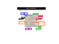
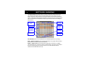
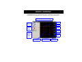
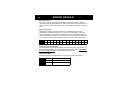
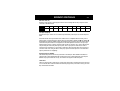
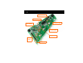
1
LQ
E6248
User Manual
E6248
2
OVERVIEW
Standalone Board Mode
A 24 key matrix panel is integrated into the E6248 together with LED key indicators. A 14-pin
header allows connection to an external matrix panel if required. To operate the board, plug it into a
live USB socket.
Main User Interface
This kit is designed for evaluation and development of QT60248 and QT60168-based behind-thepanel touch matrix circuits. It includes all circuitry and materials required to make a fully-functioning,
24-key matrix touch control. This board has a virtual RS232 serial interface via the USB port that
allows connection to a PC for function setup and data viewing. The E6248 makes use of QmBtn™
software, which is included.
Chip/ Subsidiary Interface
The QT chip on this board uses SPI for communications. This is directly available on connector J4.
For more detailed information please refer to the QT60248 datasheet.
Materials Provided:
1x E6248 eval board
1x USB cable
1x SPI cable for direct connection to the QT60248
1x CD-ROM with software and drivers (or get the latest version from www.qprox.com/toolbox)
1x User guide
2x QT60248 samples
You Will Also Need
A PC running any recent version of Windows 2000, XP or upwards, with a free USB port.
QUICKSTART
Turn to Software Installation on page 12 and follow the instructions:
• Install the QMBtn software as described — do not run the software yet
• Connect the E6248 to a free USB port on your PC with the cable provided
• Install the drivers in response to the Found New Hardware Wizard — note that this may
not be necessary if you have previously installed Quantum hardware on your PC
• Your hardware and software should now be installed correctly
Double click on the QmBtn software icon to run the program:
The software should automatically detect and configure the E6248 device — if not, please refer to
the Troubleshooter (inside back cover). The main features of the software are described on the
following pages.
Make sure that you explore all of the features of the software, in particular:
• The main window (QmBtn) which provides the ability to monitor the status of all keys
and the overall device in real time.
• The settings window (QmSettings) which allows you to adjust the behaviour of the keys
individually to explore the parameter space.
• The graph window (QmGraph) which allows you to directly monitor the analog outputs
of individual keys and effect of the associated settings parameters.
QmBtn™ is an invaluable tool for developing and testing projects that use Quantum’s QMatrix™
technology. The software is designed to communicate with a QMatrix chip via your computer’s
serial port. It allows you to monitor your chip’s status and modify its behaviour.
3
MAIN WINDOW
4
The main window (QmBtn) displays device information and the status of each key (Cmd 0x05
and 0x8k).
Open Setup
from File
Save Setup
to File
Recalibrate Selected Key
Key Calibrating
Key in Detection
Key Number
Key in Error
Signal Reference
Device Status shows
status byte return by command 0x05
Key Status shows status of
the selected (not detected)
key by command 0x8k
(where k is key number) —
click on any key to show
status
Reset
Device
Send Setup
to Device
Read Setup
from Device
Recalibrate all Keys
Main Window
APPLICATION MENU
File
Options
New
Create a new file
Open
Open a *.btn file
Save
Save the setup of the chip in the current *.btn file
Save As
Save the setup of the chip in a new *.btn file
Exit
Close the software
Beep On Key Down
Toggle option to generate PC beep on key activation
Beep On Key Up
Toggle option to generate PC beep on key release
Read After Write
Toggle option to automatically send read command
after sending new setup block
Reset After Write
Toggle option to automatically send reset command
after sending new setup block
Start/ Stop Data Log
Toggle feature to record data into a *.csv file
QmSettings
QmGraph
Advanced
Display advanced key settings
Join Data Points Draw a solid line in graph
Save Options On Close Toggle option to save software settings on close
View
Key Settings
Open the QmSettings window
Graph
Open the QmGraph window
Key Numbers
Toggle display of key numbers on keys
Key Reference Level
Toggle display of key reference level on keys
Detailed Status
Toggle display of device and key status
5
SETTINGS WINDOW
6
The settings window (QmSettings) allows you to easily visualise and modify the setup of the
chip. Clicking the Read button in the main window will bring up the current setup of your chip.
When a setup option is being modified, its value becomes bold and the Send button will become
active to indicate that the setup displayed is different from the setup on the chip. Clicking the Send
button will transfer the new setup block to the chip. The part must be reset for its new settings to
become active.
Click Here to
Make Changes to
All Keys
Key Number
Key Settings
(see below)
Option Box
value becomes
bold when
changed
Press Ctrl + Key
to select multiple
keys — changes
will then apply to
all selected keys
Global Settings
(see below)
Setups for
Individual Keys
Logging
(see below)
KEY SETTINGS (please see your datasheet for a more detailed explanation of key settings)
NTHR — Negative Threshold is used to adjust the sensitivity of a key. Higher values make keys
less sensitive. Lower values make keys more sensitive.
NDRIFT — Negative Drift is the rate at which drift compensation is carried out for a negative
going signal (when a key is touched or receives increased loading). The value is in sec/ reference
level. For a positive going signal, drift rate is fixed at 0.4 sec. Drift compensation helps to
eliminate environmental effects on the chip.
Window
7
NDIL — Negative Detection Integrator Limit allows enabling and disabling of keys and provides
signal filtering. Higher values will provide more filtering but increase the response time of the key.
FDIL — Fast Detection Integrator Limit also provides filtering, but has less effect on response
time. Total filtering is a combination of NDIL and FDIL, for more information on the detection
integrator, refer to the datasheet for your chip.
NRD — Negative Recalibration Delay determines the maximum time a key can be active before
being automatically recalibrated by the chip. The value is in seconds.
BL — Burst Length modifies key sensitivity. Higher values make the key more sensitive, lower
values have the opposite effect. The correct sensitivity for a key should be achieved with BL and
NTHR. As a general rule BL should be as low as possible and NTHR should range from 7 to 12.
AKS — Adjacent Key Suppression can be enabled or disabled. To become active, a key with
this option enabled must receive the strongest signal relative to other AKS-enabled keys.
Scope Sync sends a positive pulse (on Pin 11 S_SYNC) that brackets the burst of a selected
key.
GLOBAL SETTINGS (changes affect all keys)
Burst Spacing — Defines the interval from the start of one burst to the start of the next. Shorter
intervals result in faster touch response time; longer intervals allow higher burst lengths and
longer conversion times but slower response times.
Low Signal Limit — Sets the lowest acceptable value of signal level. If any key’s reference level
falls below this value, the device declares an error condition in the status bits.
Mains Sync — Allows the part to synchronise on the low frequency signal. This is generally used
to synchronise acquisition on the mains cycle (50/60Hz). The frequency must be more than 10Hz.
LOGGING
These settings have no effect on the chip, they define what data will be recorded when using the
Data Logger. The selected readings are recorded in a *.csv file.
8
E6248 SCHEMATIC
Note: a full PDF version of this
simplified schematic, together
with board layouts, is available
at www.qprox.com/toolbox
GRAPH WINDOW
9
The graph window (QmGraph) displays the analog signal for a selected key. This is a great tool
for determining noise level, setting the correct sensitivity and setting the level of filtering required.
The QmGraph window shows the signals for a specific key
(select a key by clicking its button in the main window)
Signal
Reference
Sets the
Origin for the
Vertical Scale
Key Signal
Negative
Hysteresis
Level
Sets the
Signal
Magnification
Factor
Negative
Threshold
Legend
Indicates
Colours of
Signal Traces
as well as
Current
Values
Signal Axis
Detect
Integrator
Axis
Lines Indicate One
Second Intervals
Detect Integrator Level
(changes colour on detect)
Right Click on
Graph for Options
BOARD DETAILS
10
USB Connector (J3)
This connector provides direct communications between the E6248 and the PC. It allows full
control over the device including calibration and setups. It also allows for real-time supervision of
signal, reference and calibration information. Uses a standard USB cable (supplied) connected to
a PC.
Matrix Connector (J2)
The E6248 has a header (J2) to allow connection to an external keyboard. The pinout is
described below. The header provides the X-Y scanning of the matrix electrode. X lines drive
charge into the matrix, and the Y lines conduct the charge back out. If an external keyboard is
used it is a good idea to disconnect the on-board matrix. To do that just cut the links to the matrix
(LK1..LK11). Links can be reconnected later by soldering a zero-ohm resistor on the link pads.
Pin
Name
1
2
3
4
5
6
7
8
9
10
11
12
13
14
GND
X7
X6
X5
X4
X3
X2
X1
X0
GND
Y2
Y1
Y0
GND
Communication Port Select (OPT1)
OPT1 allows the user to switch off the USB chip and communicate directly via the SPI port. The
SPI signal line can be found on J5. The table below shows the different options. If the USB chip
is on, do not use the SPI line as it could damage the evaluation board.
LED Behaviour (OPT2)
OPT2 allows the user to modify LED behaviour, from On/Off to Toggle. See table below.
State
ON
OFF
OPT1
USB chip on
USB chip off – all SPI line are floating
OPT2
Latch LED
Toggle LED
BOARD DETAILS
11
SPI Direct Port (J5)
Header J5 gives access to all the signals useful for communicating with the chip. The pinout of the
connector is described below:
Pin
Name
1
2
3
4
5
6
7
8
9
10
GND
+5V
+3.3V
/DRDY
/SS
MOSI
MISO
SCK
Line Sync
RST
Line Sync (J5, pin 9)
External Noise Sync: Feed a TTL or 5V CMOS synchronization pulse into pin 9 of J5 with respect to
GND.
Acquisition bursts can be synchronized to an external source of repetitive electrical noise (such as
50Hz or 60Hz) using the Noise Sync feature which can be enabled in QmBtn (View Key Settings
Global Settings). External repetitive signals are thereby heavily suppressed since the system and the
noise become synchronized and no longer beat or alias with respect to each other. The sync input
triggers the burst for key 0 (X0Y0); the device waits for the sync signal for up to 100 ms after the end
of a preceding full matrix scan (after key #23); then, when a sync pulse is received, the matrix is
scanned once in its entirety. If no sync pulse is received in 100ms, the part wakes on its own and rescans the matrix once, then goes back to sleep. Sync pulses should be spaced no more than 99ms
apart to prevent this from happening.
Oscilloscope Sync (SSYNC)
The SSYNC test point can be used to synchronize an oscilloscope. When enabled in QmBtn, this
signal provides a pulse that brackets the chosen burst or bursts, making diagnostics much simpler.
With the scope sync enabled for one key, the X matrix drive signals can be clearly seen.
LK12..LK15
These four links provide a simple way to convert 5Volts logic levels to 3.3Volts logic levels. If the host
runs at 3.3Volts, these 4 links should be disconnected (using a blade). If the host is running at 5 Volts
they should be left connected.
12
USB Connector (J3)
SPI Direct Port (J5)
LED Behaviour (OPT2)
Oscilloscope
Sync (SSYNC)
Communication
Port Select (OPT1)
Links (LK12..LK15)
Matrix
Connector
(J2)
Links (LK1..LK11)
SOFTWARE INSTALLATION
13
If you have a Quantum CD-ROM, follow these steps to install QmBtn™ software and USB
drivers. If you experience problems, make sure you have administrative rights (under
Windows 2000 or XP Pro).
Install the QmBtn™ Software
To install the QmBtn software, copy the file QmBtn[...].exe from the supplied CD to your PC. The
software can be found on the CD in folder D:\SOFTWARE\ — substitute D: with the drive letter
of your CD.
For very latest release of QmBtn, check our web site at www.qprox.com/toolbox
Install the USB Drivers
With the supplied CD-ROM in your
CD drive, connect the E6248 to
your PC with the supplied USB
cable.
Windows will display the Found
New Hardware Wizard for the
PICDEM FS USB. Select Install
the software automatically and
click Next. Windows now installs
the drivers. Click Finish when
prompted.
Windows may prompt you to
restart your PC at this point;
restarting is not necessary.
You are now done with the software and driver installation.
14
Board Will
Not
Communicate
with PC
TROUBLESHOOTER
Bad SPI or USB Connections
Check/replace cables, LEDs should display on connection
Make sure the board is getting power
Bad or Conflicting Virtual Comm Port on PC
See the Software Installation section - reinstall driver software, or,
change the USB-Serial com port number in Device Manager if there
is a conflict
Incorrect Settings on Option Switch
Set OPT1 to the ‘On’ position
Noisy or
Erratic Signal
Noisy Power Supply - try a different USB port or PC
Cables or Board too Close to Strong Noise Source (such as a power line or
switching noise source)
Increase the distance from E6248 to the noise source
Place a grounded metal shield between the noise source and the
QMatrix™ board
QMatrix™ Board is not Mechanically Stable
Prevent board from moving around
Strong RFI from a Transmitter or Adjacent Digital Product
Remove the noise source or shield against it
15
LQ
www.qprox.com
Development: Samuel Brunet, Matthew Trend
Corporate Headquarters
North America
1 Mitchell Point
Ensign Way, Hamble
Southampton SO31 4RF
United Kingdom
651 Holiday Drive Bldg. 5 / 300
Pittsburgh, PA 15220
USA
Tel
Fax
Tel
Fax
+44 (0)23 8056 5600
+44 (0)23 8045 3939
Email [email protected]
412-391-7367
412-291-1015
Copyright © 2005 QRG Ltd
All rights reserved
Patented and patents pending
REV 200.170805
Mouser Electronics
Authorized Distributor
Click to View Pricing, Inventory, Delivery & Lifecycle Information:
Atmel:
E6248