1
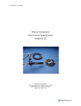
FC Series, Rev 04.03.26
Warner Instruments, Inc.
Bilayer Faraday Cage with
Vibration Isolation Table
Models FC-1 and FC-2
Warner Instruments, Inc.
1125 Dixwell Avenue, Hamden, CT 06514
(800) 599-4203 / (203) 776-0664
(203) 776-1278 - fax
Warner Instruments, Inc.
FC Series, Rev 04.03.26
Table of Contents
NOMENCLATURE.................................................................................................................................... 4
ASSEMBLY ................................................................................................................................................ 5
Overview.................................................................................................................................................. 5
Components and tools ............................................................................................................................ 5
Initial assembly ....................................................................................................................................... 5
Unpacking ............................................................................................................................................ 5
Placement ............................................................................................................................................. 6
Table ........................................................................................................................................................ 6
Cage assembly......................................................................................................................................... 7
Rear panel ............................................................................................................................................ 7
Front panels ......................................................................................................................................... 7
Side door panels ................................................................................................................................... 8
Top........................................................................................................................................................ 8
Final assembly......................................................................................................................................... 8
Alignment ............................................................................................................................................. 8
Floating the table ................................................................................................................................. 8
Electrical connections............................................................................................................................. 9
Grounding the table ............................................................................................................................. 9
Grounding the cage .............................................................................................................................. 9
APPENDIX................................................................................................................................................ 10
Specifications......................................................................................................................................... 10
Warranty and service........................................................................................................................... 11
Warranty............................................................................................................................................. 11
Service ................................................................................................................................................ 11
Warner Instruments, Inc.
FC Series, Rev 04.03.26
3
The FC-1 and FC-2 Faraday cages from Warner Instruments have been designed specifically for
research using the planar lipid bilayer. Cages are available with either active or passive
vibrations isolation tables and include several important features not available in less
dedicated enclosures. These features include a unique benchtop design, fanfold doors for easy
access to the interior, a durable powder coating, and modular construction for expandability.
Unique Features Include
Custom designed for Planar Lipid Bilayer research: The FC-1 and FC-2 have been designed
with the planar lipid bilayer specifically in mind. The intermediate size of this cage allows
the unit to easily house all components routinely used in bilayer research.
Enclosed vibration isolation table: FC series Faraday cages are designed such that the
vibration isolation table, manufactured for Warner Instruments by Kinetic Systems, Inc., is
completely contained within the enclosure. This approach allows the cage to provide
complete EM shielding while mechanically isolating the table top from the cage walls.
Benchtop design: These units have a small (18 x 22”) footprint and are designed to be
placed on any sturdy benchtop. This feature allows the cage to be placed into crowded
laboratory environments without the need to clear floor space for a larger, more
cumbersome vibration isolation rig.
Fanfold front doors: Access to the cage interior is provided by several large doors, including
two fanfold doors on the cage front. The fanfold design allows the user to easily access the
benchtop on either side of the cage enclosure when these doors are open.
Modular construction to accommodate add-on components: The modular design of FC series
Faraday cages allows for introduction of expansion kits and add-on components. For
example, replacing a door panel with a screen door, or introducing a perfusion system is a
straightforward and simple procedure.
Part of the complete Bilayer Workstation: FC series Faraday cages are designed to be an
integral part of the complete Bilayer Workstation from Warner Instruments. As such, the
cage is engineered to accommodate all current and planned workstation components.
Warner Instruments, Inc.
4
FC Series, Rev 04.03.26
NOMENCLATURE
Text conventions
To minimize the potential for confusion, we have employed several text conventions which
are specified below. Since our goal is to provide clarity rather than complexity, we welcome any
feedback you may wish to provide.
Warner Instrument product numbers are presented using bold type.
References to Faraday cage panels are specified using
UNDERLINED SMALL CAPS.
References to specific components on a Faraday cage panel are specified using
UNDERLINED SMALL CAPS.
NON-
References to component settings are specified in italic type.
Special comments and warnings are presented in highlighted text.
Any other formatting should be apparent from context.
THIS EQUIPMENT IS NOT DESIGNED NOR INTENDED
FOR USE ON HUMAN SUBJECTS
Warner Instruments, Inc.
5
FC Series, Rev 04.03.26
ASSEMBLY
Overview
This Faraday cage has been pre-assembled at the factory as a quality control measure but
is shipped disassembled to reduce transportation costs. These savings are passed to the
customer.
The general procedure for assembly is as follows:
a) Position the Faraday cage base on a sturdy surface.
b) Insert the vibration isolation table into the cage bottom.
c) Complete the frame of the cage by attaching the back, front, and top panels.
d) Attach the side panels to the frame.
e) Float the table.
f)
Make adjustments and electrical connections.
Components and tools
The unassembled Faraday cage is comprised of the following components:
•
CAGE BOTTOM
(base or pan): black, wing doors on each side, rectangular opening on
rear.
•
CAGE TOP:
•
REAR PANEL: black, has large brass grounding block and two small rectangular openings
for electrical access to cage interior.
•
SIDE DOOR PANELS
•
FRONT DOOR PANELS
•
package containing: 3/8” nuts with attached lock-washers (34)
•
grounding cable.
•
this manual.
black, has large door which opens to front
(2): blue-gray, left and right sides, large doors open to front.
(2): blue-gray, left and right sides, fanfold doors, right side door
identifiable by Warner logo.
You will need a 3/8” box-end wrench to complete assembly. The cage can be easily
assembled by a single user due to its slot-and-fit design.
Initial assembly
Unpacking
Begin by completely unpacking the cage from its shipping container. Check to ensure all
components are present and undamaged.
Open, but do not unpack, the vibration isolation table shipped to you from Kinetic
Systems, Inc. Read the setup instructions for the table to familiarize yourself with its
operation prior to assembling the cage.
Warner Instruments, Inc.
FC Series, Rev 04.03.26
6
Placement
In general, the effectiveness of a vibration isolation table is optimized by placing it where
large amplitude building vibrations are at a minimum. These locations include the building
ground or basement floors, or near a main support column on upper floors. Unfortunately,
the best placement of a table is a pragmatic effort and you may find it necessary to relocate
the bilayer workstation if the noise contribution from the building is excessive.
Since the FC Series Faraday cage encloses the vibration isolation table, the cage must be
placed on a sturdy benchtop for the table to perform correctly. The benchtop should
provide a stable work service and must be capable of supporting the weight of the
table/cage assembly as well as the other components of the workstation (minimum 200
lbs.).
•
Place the Faraday cage BASE onto the benchtop such that the wing doors are positioned
along the sides and the rectangular opening is along the back.
•
Open the wing doors.
NOTES
1. Consider the placement of the BASE carefully since it will be more difficult to move once
the table and cage enclosure are assembled. However, if you must relocate the cage,
move the cage base and table separately. You can gain access to the table by removing
the cage from the pan.
2. Be sure to allow sufficient space in the surrounding area for your equipment and
supplies!
Table
The vibration isolation TABLE is placed into the Faraday cage BASE once the pan has
been positioned. Familiarize yourself with the assembly and operation of the TABLE prior to
removing it from its shipping container to avoid damaging it during placement.
NOTE: The table weighs approximately 100 lbs, we recommend the use of an assistant to
move and position the table.
While not required, we recommend that the TABLE be grounded to the Faraday cage
enclosure. This is achieved by making a connection between the brass bolt on the
underside of the table and the brass GROUNDING BLOCK on the rear wall of the Faraday cage.
A grounding cable with a lug on one end and a banana plug on the other end is supplied
for this purpose.
•
Before removing the TABLE from its shipping container, attach the supplied ground wire
to the stud on the back corner of the underside of the vibration isolation table.
Connection from the TABLE to the cage will be made at a later time.
•
Remove the TABLE with attached ground wire from the shipping carton and place it in
the CAGE BOTTOM so that the leading edge of the tabletop is 3/4 to 1 inch from the front
Warner Instruments, Inc.
7
FC Series, Rev 04.03.26
of the pan. (The front of the table is easily identified by a large decal with the word
‘Benchmate’.)
NOTE: Use care to not jam your knuckles as you place the table into the pan!
•
Position the
table.
•
Make sure that any leveling controls on the rear of the TABLE (not available on all
models) are visible in the rectangular opening on the rear of the PAN.
•
Make sure that the previously attached ground wire is routed out through the lefthand wing door. Make sure the ground wire is not trapped under the feet of the table.
•
Route any required air pressure lines (not available on all models) from your air source,
through the opening on the rear of the CAGE BASE, to the input port on the table.
•
Do not float the table at this time.
TABLE
so that the wing doors do not obstruct any leveling controls on the
Cage assembly
Once the vibration isolation TABLE has been positioned in the cage BASE the remainder
of the Faraday cage is assembled onto the pan. The general procedure is to first attach the
REAR PANEL, followed by the two FRONT DOORS. The SIDE PANELS are then mounted. The frame
construction is completed by attaching the cage TOP to the back and front panels. Finally,
the whole cage assembly is aligned and secured by tightening the lock-nuts.
Rear panel
•
Mount the REAR PANEL to the BASE by sliding the pem-studs into the associated slots on
the BASE. Position the REAR PANEL so that the brass GROUNDING BLOCK is within the cage
enclosure and is immediately adjacent to the tabletop.
•
Attach, but do not tighten, lock-nuts to all the pem-studs along the bottom of the
PANEL.
REAR
Front panels
•
Mount the FRONT DOORS to the cage
by the presence of the Warner logo.
•
Attach, but do not tighten, lock-nuts to the pem-studs on the bottom of each door
panel.
BASE.
The right hand door panel is easily identified
NOTE: Doors may be mounted in any order. You may need to gently tap them into
place. If necessary, doors can be held in position by tightening the lock-nuts finger
tight.
Warner Instruments, Inc.
8
FC Series, Rev 04.03.26
Side door panels
The next step is to attach the
SIDE DOOR
panels to the frame.
•
Begin by mounting one SIDE PANEL to the Faraday cage. Place the panel into position by
pushing the pem-studs through their respective holes in the frame and secure into
place with lock-nuts. Do not tighten yet.
•
Mount the other
SIDE PANEL.
NOTES: (1) Left and right DOOR PANELS are easily identified by noticing that both door
panels have a small hole along their bottom edge and open to the front. (2) At this time,
do not secure the wing doors on the cage BASE to the SIDE PANELS.
Top
The assembly of the frame is completed by attachment of the cage
TOP.
•
Begin by aligning the slots on the cage
not tap into place yet.
•
Now, gently align the pem-studs on the side and front of the
the slots on the TOP.
•
Once the top is in position, tap it into place and tighten all lock-nuts finger tight
TOP
with the pem-studs on the
REAR PANEL.
FRONT DOOR
Do
panels with
Final assembly
The assembly of the cage is completed by aligning the front doors, tightening all lock-nuts
and floating the table.
Alignment
•
Begin by tightening the lock-nuts holding the
BASE.
•
Once these have been secured, tighten the lock-nuts along the top of the
•
Next, square the cage enclosure and tighten the lock-nuts on the front doors.
REAR PANEL
and
FRONT DOORS
to the cage
REAR PANEL.
NOTE: The cage is considered ‘square’ when the front doors align to each other when
they are closed. It may not be necessary to ‘square’ the cage before tightening these
nuts. However, if necessary, front door lock-nuts can be accessed through the side
doors.
•
Finally, open the front doors and tighten all remaining lock-nuts.
Floating the table
After making all necessary mechanical connections, float the TABLE following the
instructions provided by Kinetic Systems. The top of a properly floated TABLE should be
approximately level with the top of the front edge of the CAGE BASE (visible when the front
doors are open).
Warner Instruments, Inc.
9
FC Series, Rev 04.03.26
Electrical connections
Grounding the table
The vibration isolation TABLE is grounded to the Faraday cage by connecting the GROUND
CABLE attached to the underside of the TABLE to the brass GROUNDING BLOCK on the rear wall
of the cage.
If you attached and positioned the GROUND CABLE to the TABLE during assembly, it should
now be re-routed from the left side access door to the brass GROUNDING BLOCK.
Grounding the cage
The BRASS BLOCK mounted on the cage REAR PANEL is provided as a common ground point
for all instrumentation contained within the cage which require a ground.
The completed Faraday cage assembly is grounded by running a cable from this BRASS
BLOCK to the chassis or circuit ground connections on the rear of your voltage clamp
amplifier. Follow the instructions provided by the amplifier manufacturer for proper
routing of this cable.
This completes the assembly of the FC series Faraday cage with
enclosed vibration isolation table. Continue assembly of your
bilayer workstation following the instructions provided with those
components.
Please contact Warner Instruments if you have any comments,
questions or difficulties.
Warner Instruments, Inc.
10
FC Series, Rev 04.03.26
APPENDIX
Specifications
Dimensions:
25 x 22 x 18” (H x W x D)
Materials:
Aluminum with powder coat finish. Solid brass grounding block.
Design:
Electrically continuous cage with solid wall construction. Cage base
accommodates 16 x 19” vibration isolation table (either passive or active
support) manufactured by Kinetic Systems, Inc. Table top forms floor of
cage.
Dual fan-fold front doors with magnetic closures. Large panel side doors
with magnetic closures. Large panel door on top. Cage base has small
doors for access to vibration isolation table controls. Access ports for
electrical connection to cage contents.
Table:
Specifications are provided in the user's manual from Kinetic Systems.
Warner Instruments, Inc.
11
FC Series, Rev 04.03.26
Warranty and service
Warranty
The FC Series Faraday cages are covered by our Warranty to be free from defects in
materials and workmanship for a period of one year from the date of shipment. If a failure
occurs within this period, we will either repair or replace the faulty component(s). This
warranty does not cover failure or damage caused by physical abuse or electrical stress.
In the event that repairs are necessary, shipping charges to the factory are the customer's
responsibility. Return charges will be paid by Warner Instruments, Inc.
The BenchMate vibration isolation table is waranteed by Kinetic Systems, Inc. Please direct
any questions regarding the operation and manufacture of the table with them. Their
contact information is:
Kinetic Systems, Inc.
20 Arboretum Road
PO Box 414
Boston, MA 02131
(800) 992-2884
(617) 522-8700
(617) 522-6323 - fax
Service
Normal business hours are 8:30 AM to 5:00 PM (EST), Monday through Friday.
Our offices are located at:
1125 Dixwell Avenue
Hamden, CT 06514
We can be reached by phone at:
(800) 599-4203 or (203) 776-0664
(203) 776-1278 - fax
In addition, we can be reached by e-mail at [email protected] or through our web
page at http://www.warneronline.com
Warner Instruments, Inc.