1
Instrumentation Scientifique de Laboratoire
User's Manual
CPP 5Gs
Instrumentation Scientifique de Laboratoire - BP 70285 - 14653 CARPIQUET CEDEX FRANCE
Phone : (+33) 2.31.26.43.00 Fax : (+33) 2.31.26.62.93 Web Site: http://www.isl-france.com
Page 2
CPP 5Gs User's Manual
DOCV223A001-F
CPP 5Gs
Historical Review
§ concerned
Revision
Modification descriptive
Date
Creation
00/10/01
index
A
B
Appendix E §1.5 & 2.5
Appendix F
C
D
E
F
DOCV223A001-F
Modification of constructive elements of cloud and pour points detection
heads.
Insertion of spare part list.
Section 1 § 2.4 ; 2.5
Rapid cooling method description; prestored programs list update
Section 2 § 6.3.2
Pour program cooling profile description.
Section 2 § 8.4
Description of new jacket temperature checking procedure.
Section 2 § 9.2
Warning alarm list update.
Section 2 § 9.7
Update of service configuration menu.
Update of regulation parameters entry menu.
Section 2 § 9.7.1
Description of reheating stage at the end of test.
General § 6.2
Welcome screen: language choice at power on
Part 1 § 2.62
Auto edition function
Part 2 § 5.6
Printer configuration menu
Part 2 § 6.2
Starting of the tilting tests at Tp + 9°C – (x test frequency)
Part 2 § 9
Alarms treatment with historical
Configuration menu at power on: locking of the language choice et
Part 2 § 10.1
configuration of the auto edition function
Part 2 § 10.3.2
Failure alarms update: sample temperature alarm
Part 2 § 10.3.3
Warning alarms update
Appendix B
Description of the communication protocol of the RS 232C link
Storing of tests without results
Part 2 § 4
Printing of tests without result
Part 2 § 5.1
Updating of flags
Part 2 § 7.2
Updating of message formats of results sent through the RS 232C link
Appendix B § 5.2
Mounting and using the Manual CFPP Kit
Appendix E
Updating of ISL Company profile
General § 1
Addition of DIN ISO3016 standard method
General § 2
Updating of sections 4.3.3.1 “RS 232C serial link” and 4.3.3.2 “RS485 serial
General § 4.3.3
link – Connection to ALAN® Network”
Adding of a list of operator names: Updating of Diagram 1 “Test Launch
Part 1 § 2
Diagram”
Use of the Opér. key with the list of prestored operator names
Part 1 § 2.4.1
Updating of diagrams of main level screens: The Program menu is replaced
Part 2
by the Run Environment menu
Modification of title; Updating of diagram 4: The Run Environment menu;
Part 2 § 6
Adding of section 6.4: Operator name list setting menu
Adding of screen 4 of the Diagnostic menu: endurance of the cooling unit
Part 2 § 7.2
accessible from the level 2
Modification of the warning alarm setup menu
Part 2 § 10.2.1
Updating of printout examples: adding of the cooling unit serial number in
Appendix A
the heading
Updating of Test Launch Diagram (list of operator names available)
Appendix C
CPP 5Gs User's Manual
01/11/15
03/03/03
03/07/23
05/05/04
04/10/05
Page 3
ISL(c) copyright
The ISL CPP 5Gs Analyzers and this manual are protected by copyright.
Reproduction of the unit will result in prosecution.
All rights to the manual are reserved. Reproduction in any form, including in the form of excerpts, shall require written
permission from the copyright holder.
ISL CPP 5Gs Software(c) 2000, ISL
This present software is owned by ISL and is registered under number IDDN.FR.001.260023.00.R.P.2000.000.30000 with the
« Agence pour la Protection des Programmes », 119 Avenue de Flandre - 75019 Paris. It is protected in France by the « Code
de Propriété Intellectuelle » laws and internationally by international treaty provisions, and all other applicable national laws.
It must not be copied, reproduced, adapted, translated, rented or disassembled. This also applies to the accompanying
manuals.
INFORMATION
Information in this document is subject to change without notice and does not represent a commitment on the part of ISL. ISL
provides this document "as is", without warranty of any kind, either expressed or implied, including, but not limited to, the
particular purpose. ISL may make improvements and/or changes in this manual or in the product(s) and/or the program (s)
described in this manual at any time. This product could include technical inaccuracies or typographical errors. Changes are
periodically made to the information herein; these changes may be incorporated in new editions of the publication.
Reproduction of any part of this manual without express written permission is forbidden.
Translation in foreign local language (other than French or English)
Translation in other language than French and English have no contractual value and have been performed under
responsibility of the local distributor.
In any case the reference of the present literature will be the French and/or English release provided under ISL copyright.
Page 4
CPP 5Gs User's Manual
DOCV223A001-F
CPP 5Gs
Reserved for public relations department
N° ................................
Date .............................
CUSTOMER
REPORT
PURPOSE
I wish to
Report an error
Submit a suggestion / a comment
Get more information
In the area of
Hardware
Software
Manual
ANALYZER ENVIRONMENT (please be complete)
• HARDWARE
Type of analyzer: ......................................
Serial N° : ...................................................
Options:
Parallel printer
Graphic printer
RS232C interface
Current loop interface
Plotter
Other : ......................................................
• SOFTWARE
Version : ........................................................
ATTACHED SHEETS
Listing
Diskette
Drawing
Text
Other
PROBLEM DESCRIPTION / COMMENTS
SUBMITTED BY
Name :
Company :
Address :
Phone :
Fax :
Date:
Send this report to your local Sales office or to Groupe ISL - Service Clients
BP 70285
14653 CARPIQUET CEDEX FRANCE
Tel : (+33) 2.31.26.43.00 – Monday through Friday from 9 :00 a.m. to 5 :00 p.m. French Time
Fax : (+33) 2.31.26.62.93
Web: http://www.isl-france.com/
DOCV223A001-F
CPP 5Gs User's Manual
Page 5
Page intentionally blank.
Page 6
CPP 5Gs User's Manual
DOCV223A001-F
CPP 5Gs
Warning
The ISL Analyzer you have just purchased has been designed and built with care to
ensure safety and reliability in operation
However, using the analyzer involves the handling of chemicals which may be
hazardous (e.g., flammable or toxic). You should therefore be watchful and take
every precaution to prevent accidents.
We advise you to:
• read the manual carefully
• wear adequate protective clothing
• take all the maintenance steps suggested
• exercise caution to avoid accidents
ISL disclaims all liability with respect to the usage of the instruments it
manufactures.
Use of Non-ISL Products and Accessories. Defects or damage that result from the
use of Non-ISL branded or certified Products, Accessories, Software or other
peripheral equipment are excluded from warranty.
DOCV223A001-F
CPP 5Gs User's Manual
Page 7
Page intentionally blank.
Page 8
CPP 5Gs User's Manual
DOCV223A001-F
CPP 5Gs
CONTENTS
GENERAL
...................................................................................................................................................... 13
1. INTRODUCTION ...............................................................................................................................................13
1.1. ISL Company Profile ...............................................................................................................................13
1.2. Type conventions .....................................................................................................................................14
1.3. About this manual ....................................................................................................................................14
2. ANALYZER TYPE .............................................................................................................................................14
3. PRECAUTIONS TO BE OBSERVED BY USERS ......................................................................................................15
3.1. Meaning of symbols .................................................................................................................................15
3.2. Precautions applicable to analyzers with built-in refrigeration system ..................................................15
4. UNPACKING AND INSTALLATION.....................................................................................................................15
4.1. Precautions when unpacking ...................................................................................................................15
4.2. Installing the CPP 5Gs: Unlocking the shock-absorbers .......................................................................15
4.3. Connections .............................................................................................................................................16
4.3.1. Connecting to the electric power supply .............................................................................................................16
4.3.2. Connecting the sample temperature probe ..........................................................................................................16
4.3.3. CPP 5G/s / PC link..............................................................................................................................................16
4.3.3.1. RS 232C serial link
16
4.3.3.2. RS485 serial link – Connection to ALAN® Network
17
4.3.4. Connecting a printer............................................................................................................................................17
4.3.5. "SERVICE" port .................................................................................................................................................17
4.4. Analyzer rear panel and connectors ........................................................................................................18
5. INSTRUMENT DESCRIPTION .............................................................................................................................19
6. USER INTERFACE ............................................................................................................................................20
6.1. Instrument front panel .............................................................................................................................20
6.1.1. LCD screen .........................................................................................................................................................20
6.1.2. Backlight setting .................................................................................................................................................20
6.1.3. Control keys .....................................................................................................................................................1-21
6.2. Welcome screen ................................................................................................................................... 1-21
PART 1
USING THE CPP 5GS WITH PRE-INSTALLED PROGRAMS...............................................1-23
1. INTRODUCTION ........................................................................................................................................... 1-25
2. FIRST TEST .................................................................................................................................................. 1-25
2.1. Preparing sample................................................................................................................................. 1-26
2.2. Cloud point measuring head................................................................................................................ 1-26
2.3. Pour point measuring head.................................................................................................................. 1-26
2.4. Sample analysis ................................................................................................................................... 1-27
2.4.1. In cloud mode ..................................................................................................................................................1-27
2.4.2. In "Pour" mode ................................................................................................................................................1-28
2.4.3. In "Manual" mode............................................................................................................................................1-29
2.4.4. In "Pour" mode - Rapid Cooling Mode...........................................................................................................1-29
2.5. Programmed temperature profiles....................................................................................................... 1-30
2.6. Text entry screen.................................................................................................................................. 1-31
2.6.1. Text entry.........................................................................................................................................................1-31
2.6.2. Auto edition .....................................................................................................................................................1-31
DOCV223A001-F
CPP 5Gs User's Manual
Page 9
PART 2
ADVANCED USED OF THE CPP5GS ......................................................................................... 2-33
1. INTRODUCTION ............................................................................................................................................2-35
2. MAIN MENU .................................................................................................................................................2-35
3. ACCESS LEVELS AND PASSWORD: "ACCESS" MENU ....................................................................................2-37
4. RESULTS DISPLAY: "RESULTS" MENU .........................................................................................................2-38
5. PRINTING: "PRINTING" MENU ......................................................................................................................2-39
5.1. Printing results .....................................................................................................................................2-40
5.2. Printing test program parameters ........................................................................................................2-41
5.3. Printing calibration ticket ....................................................................................................................2-41
5.4. Printing ongoing test results ................................................................................................................2-41
5.5. Printing test ..........................................................................................................................................2-42
5.6. Printer setup .........................................................................................................................................2-42
6. TEST SETTING: THE "RUN ENVIRONMENT" MENU ........................................................................................2-43
6.1. Test program - cloud method ...............................................................................................................2-43
6.2. Test program - pour method.................................................................................................................2-46
6.3. Cooling profile: "Cooling profile" menu.............................................................................................2-48
6.3.1. Cooling profile – cloud method....................................................................................................................... 2-48
6.3.2. Cooling profile – pour method ........................................................................................................................ 2-49
6.4. Operator name list................................................................................................................................2-51
7. MEASUREMENTS AND DIAGNOSTICS: "SERVICE" MENU ..............................................................................2-52
7.1. Service menu ........................................................................................................................................2-52
7.2. Diagnostic menu...................................................................................................................................2-53
7.3. Cooling unit diagnostic ........................................................................................................................2-54
8. CALIBRATION: "QUALITY" MENU ...............................................................................................................2-55
8.1. Sample temperature measurement calibration: "Sample Temp Calib." menu .....................................2-56
8.2. Probe correction chart: "Cloud table" and "Pour table" menus..........................................................2-57
8.3. Jacket temperature measurement calibration: "Jacket Temp. Calib." menu » ...................................2-57
8.4. Jacket temperature measurement checking: the “Jack.T.Check." menu ..............................................2-59
9. ALARM TREATMENT ....................................................................................................................................2-60
9.1. Types of alarm......................................................................................................................................2-60
9.1.1. Failure alarms.................................................................................................................................................. 2-60
9.1.2. Warning alarms ............................................................................................................................................... 2-60
9.2. Displaying alarms, stopping the buzzer ...............................................................................................2-60
9.3. Alarm processing..................................................................................................................................2-60
9.4. Alarm historical....................................................................................................................................2-61
10. CONFIGURATION: "SETUP" MENU .............................................................................................................2-62
10.1. Power-on parameters: "Start" menu ................................................................................................2-63
10.2. Alarms setup: "Alarms setup" menu .................................................................................................2-63
10.2.1. Programming the audible alarm .................................................................................................................... 2-63
10.2.2. List of failure alarms and setting................................................................................................................... 2-64
10.2.3. List of warning alarms .................................................................................................................................. 2-65
10.3. Customizing and access authorization to level 1: "Laboratory setup" menu ....................................2-66
10.4. Printer setup: "Print" menu..............................................................................................................2-66
10.5. CPP 5Gs
PC: "PC link setup" and "RS 2332 link setup" menus.................................................2-66
10.5.1. RS 232 C link configuration: "RS 232 C link setup" menu.......................................................................... 2-67
10.5.2. PC link configuration: "PC link setup" menu............................................................................................... 2-68
10.6. Adjusting Date/time: "Adjust Date/time" menu .................................................................................2-68
10.7. "Service setup" menu.........................................................................................................................2-69
10.7.1. Entering regulation parameters: "Regulation parameters" menu................................................................... 2-69
10.7.2. Entering calibration values: "Modify calibration values" menu................................................................... 2-70
10.7.3. Changing sample temperature calibration values.......................................................................................... 2-70
10.7.4. File uploading/downloading: "Upload/Download" menu ............................................................................ 2-70
10.7.4.1. File transfer principle
2-70
10.7.4.2. Download program installation and startup
2-70
10.7.4.3. Transfer request by operator
2-70
10.7.4.4. Failed transfer, or screen remains dark
2-71
Page 10
CPP 5Gs User's Manual
DOCV223A001-F
CPP 5Gs
APPENDIX A EXAMPLES OF PRINTOUT TYPES...................................................................................... 73
1 - 80-COLUMN RESULT PRINTOUT ......................................................................................................................75
2 - 80-COLUMN INTERNAL PARAMETER PRINTOUT ..............................................................................................76
3 - 80-COLUMN CALIBRATION TICKET PRINTOUT.................................................................................................77
4 - 80-COLUMN MEASUREMENT PRINTOUT ..........................................................................................................77
5 - PRINTING TEST ...............................................................................................................................................77
APPENDIX B
RS232 LINK FEATURES ON CPP 5GS.................................................................................. 79
1 - INTERFACE FEATURES ....................................................................................................................................81
2 - OUTLET CONNECTOR BROACHING ..................................................................................................................81
3 - COMMUNICATION PROTOCOLS .......................................................................................................................82
4 - ENQ/ACK PROTOCOL DETAILS .....................................................................................................................83
5 - TRANSMITTED DATA ......................................................................................................................................84
5.1 - Message format.....................................................................................................................................84
5.2 - Result message......................................................................................................................................85
5.3 - Context message ...................................................................................................................................85
5.4 - Program message .................................................................................................................................86
5.5 - Cooling profile message ......................................................................................................................86
6 - RS232C LINK TEST ........................................................................................................................................86
APPENDIX C DIAGRAMS ................................................................................................................................ 87
1 - TEST LAUNCH DIAGRAM ................................................................................................................................89
2 - ACTION CHART ..............................................................................................................................................90
APPENDIX D MAINTENANCE OF MEASURING HEADS......................................................................... 91
1 - MAINTENANCE OF THE CLOUD POINT MEASURING HEAD................................................................................93
1.1 - Taking apart of the cover......................................................................................................................93
1.2 - Taking apart of the receiver..................................................................................................................94
1.3 - Taking apart of the emitter ...................................................................................................................95
1.4 - Taking apart of the temperature probe .................................................................................................96
1.5 - New cloud point detection head compatibility ......................................................................................97
2 - MAINTENANCE OF THE POUR POINT MEASURING HEAD .................................................................................98
2.1 - Taking apart of the cover......................................................................................................................98
2.2 - Taking apart of the receiver..................................................................................................................99
2.3 - Taking apart of the emitter .................................................................................................................100
2.4 - Taking apart of the temperature probe ...............................................................................................101
2.5 - New pour point detection head compatibility .....................................................................................102
APPENDIX E
USING THE MANUAL CFPP KIT ON THE CPP 5GS IN MANUAL MODE................. 103
1 - PREPARING THE SAMPLE ..............................................................................................................................105
2 - SETTING UP AND ADJUSTMENT OF THE SUCTION KIT ....................................................................................106
3 - JACKET PREPARATION ..................................................................................................................................106
4 - ASSEMBLY OF THE FILTER AND MEASURING UNIT ON THE ANALYZER ..........................................................107
5 - TEST RUNNING IN MANUAL MODE ................................................................................................................108
6 - PACKING LIST ..............................................................................................................................................109
INDEX
.................................................................................................................................................... 111
CPP 5GS SPARE PART LIST ........................................................................................................DOCV223X200
DOCV223A001-F
CPP 5Gs User's Manual
Page 11
Page intentionally blank.
Page 12
CPP 5Gs User's Manual
DOCV223A001-F
General
1.Introduction
1.1.ISL Company Profile
We would like to take this opportunity to thank you for choosing ISL product. We are confident that you will be
completely satisfied with your new Analyzer and we hope that you continue to call on us for all of your
laboratory’s petroleum testing needs. Before you begin, we ask you to take a few minutes to become acquainted
with ISL and its history.
ISL’s beginnings go back to 1975, when a group of engineers and scientists from the heart of the Northern
France’s petrochemical industry began seeking ways to automate petroleum testing. The neighboring industry
served as an excellent research and development proving ground for their new equipment.
By the end of 70’s, several quality instruments had been developed and were being marketed in Europe under
ATPEM Trademark.
The most famous of these new instruments was the CPP 97, Automatic Cloud and Pour Point Analyzer. Introduced
in the early 1980’s, its successor, the CPP97-6, revolutionized cold flow testing enabling up to six tests
automatically and simultaneously.
Adding new automatic instruments each year, ATPEM soon became a worldwide leader in automatic petroleum
test instrumentation. In 1986, they expanded operations, reorganizing into the company now knows as ISL.
Striving to maintain close contact with customers in over 75 countries, ISL has since grown, founded Sales &
Service branches on each continent. With design, marketing, service and support operating together under the ISL
roof, the company reached “a new dimension” in 1993 by obtaining ISO 9002 certification from the BVQI.
Working hard to extend our quality assurance program, we received ISO 9001 certification in 1995.
Though best known for distillation, viscosity testing, cold behavior instrumentation, flash point, evaporation loss,
oxidation, and asphalt testing equipment, ISL's contributions to automated petroleum testing continue to grow.
With more than 10 patents to date, ISL's constant research into new technologies buttresses our precedent for
ultimate precision, performance and safety. The company now offers over 20 Automatic Analyzers for different
applications giving incontestable benefits to its users in increasing of test precision by elimination of operator
subjectivity and human errors, while increasing productivity and reduces operator time with highest level of safety.
A worldwide distribution network supports our customers with quick, efficient service, and our highly
knowledgeable service staff buttresses this relationship, providing solutions to product or application challenges.
Please visit our web site for more information: http://www.isl-france.com .
DOCV223A001-F
CPP 5Gs User's Manual
Page 13
CPP 5Gs
1.2.Type conventions
Convention
Bold
Bold Italics
Bold + SMALL
CAPITALS
Meaning
Important words or sentences
Menus or buttons displayed on LCD screen
Keys on instrument
front panel
1.3.About this manual
This manual consists of the following main sections:
1. 0:Using the CPP 5Gs with pre-installed programs.
2. Part 2: Advanced utilization of the CPP 5Gs.
0 will enable an operator to use the CPP 5Gs for a first cloud-point and pour-point test in a few easy stages, with
no specific prior knowledge.
As to Part 2, it is intended to permit users to take full advantage of the instrument's potential. It is directed at
experienced users who have a working knowledge of testing from levels 1 and 2. In any event, the sensitive
sections of the CPP 5Gs control software, namely those relating to test parameters can be read- and write-protected
through a combination of passwords selected by the user.
All CPP 5Gs have a built-in refrigeration system.
2.Analyzer type
The CPP 5Gs is a fully automatic instrument designed for measuring cloud point as per Standards ASTM D 2500,
ASTM D 5771, IP 219, IP 444, ISO 3015 and JIS K2269, as well as pour point as per Standards ASTM D 97,
ASTM D5853, ASTM D5950, IP 15, IP 441, ISO 3016, DIN ISO 3016, NF T60-105 and JIS K2269. Cloud and
pour point tests are used in connection with most products (ship and land-based Diesel engine fuels, power
generation fuels, lubricants, white oils, etc…).
By definition, the cloud point test permits determining the temperature at which the paraffin-base constituents of
the product may precipitate, a reaction which may cause pipework or filter clogging, or the downgrading of
performance in the case of oils. As to the pour point test, it yields the lowest temperature at which the product
continues to flow. That information is particularly relevant to the storage of products which must be pumped out
afterwards. Pour point is generally 4.5°C to 5.5°C below cloud point, although the difference between those two
points may be as much as 8 to 11°C..
The distinctive feature of this instrument is its versatility, as its setup is fully adjustable. It is designed to run
programs based on customized sets of parameters selected to suit users' requirements. This major advantage makes
the instrument suitable not only for conventional testing, but also for R & D work. Further, versatility has not been
achieved to the detriment of operating convenience. As will be seen in the next chapters, the instrument is just as
easy to operate as it is versatile. ISL has devoted much care to the design and construction of this instrument and
we hope it will give you full satisfaction.
Page 14
CPP 5Gs User's Manual
DOCV223A001-F
3.Precautions to be observed by users
3.1.Meaning of symbols
Note
Important remark.
CAUTION !
Special attention required.
Refer to
Refer to document (e.g., standard) or other manual.
3.2.Precautions applicable to analyzers with built-in refrigeration system
Analyzers with built-in refrigeration system feature a refrigerating compressor which requires a few specific
precautions to ensure analyzer durability and optimum performance:
• Do not operate the analyzer on a support structure which may vibrate. Support and compressor vibrations may
become resonant, thereby damaging the analyzer.
• Analyzer optimum operating temperature is about 20°C. To prevent overheating, which would be detrimental
to instrument performance, make sure that:
1. There is free space at the back of the instrument ot permit effective heat dissipation.
2. There are no obstructions on the ventilation louver side. Louvers should be kept dust-free using a blowgun to
prevent fouling.
4.Unpacking and installation
4.1.Precautions when unpacking
After unpacking, inspect the analyzer and its accessories and check for any damage in transport which should be
immediately notified to the carrier for claim purposes.
All parts of the CPP 5Gs have been carefully inspected and tested before shipping. However, it is advisable to
verify that the equipment received is consistent with the attached packing slip.
When receiving the CPP 5Gs, unpack all its components.
Place the analyzer on a bench top close to electrical outlets, leaving enough clearance space for easy access to
connectors at the back of the instrument.
For further details on refrigeration unit, refer to ISL specifications.
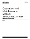
4.2.Installing the CPP 5Gs: Unlocking the shock-absorbers
The CPP 5Gs refrigerating compressor is supported by a vibration mount which must be locked during transport.
The mount locking screws purposely protrude from the underside of the instrument to prevent it from resting
evenly on the bench top, as a reminder to remove the screws.
Therefore, the first steps after unpacking should be:
1. To remove the vibration mount locking screws located under the instrument.
2. To store the screws at the back of the analyzer as shown below.
DOCV223A001-F
CPP 5Gs User's Manual
Page 15
CPP 5Gs
Vibration mount locking screw
Storing locking screws at back of analyzer
Figure 1: Locking/unlocking vibration mount
4.3.Connections
4.3.1.Connecting to the electric power supply
After unpacking the CPP 5Gs, make all the required connections to the accessories, network and systems.
It should be noted that the CPP 5Gs is designed for 90-130 V and 180-250 V, 50/60 Hz power, which should cover
conditions in most of the countries where it is commercially available. The instrument is delivered with a power
cord suitable for the country where it was sold.
4.3.2.Connecting the sample temperature probe
1. Connect the probe LEMO plug to the appropriate front panel socket.
2. Insert probe into the probe carrier at instrument top.
4.3.3.CPP 5G/s / PC link
The CPP 5Gs analyzer is fitted as standard with an RS 232C interface and an RS485 interface.
4.3.3.1. RS 232C serial link
The network input / output ports of the analyzer link interface with the
ALAN® network may be connected via a special adapter supplied with
the analyzer to form an RS 232C serial link enabling results to be
collected on a PC and for transmission to a LIMS (see Appendix B –
“RS232 link features on CPP 5Gs” page 79 for more precision on the
communication protocol of the RS 232C link and the meaning of the
message content).
Use the adapter supplied with the analyzer (see the Packing List): it
has two RS485 connectors on one side, which have to be connected
simultaneously to the analyzer’s ALAN® input and output ports, and
on the other side an RS 232C connector to be connected to the PC.
Note: ISL analyzers allow transmitting data according to specific customized criteria and a
user defined protocol.
The RS 232C communication interface has to be parameterized. Refer to the section 10.5.1 –
“RS 232 C link configuration: "RS 232 C link setup" menu” page 2-67.
Page 16
CPP 5Gs User's Manual
DOCV223A001-F
®
4.3.3.2.RS485 serial link – Connection to ALAN Network
The CPP 5Gs has been designed to run under the ALAN® management software developed by ISL:
The ALAN® software (Automatic Laboratory Analyzer Network) is a multitasking software running under
Windows© and allowing up to 31 ISL analyzers to be connected to the same PC computer (see the illustration
below). It allows data coming from different ISL analyzers to be collected and stored.
Besides multi-analyzers results database management and control (according to the analyzer type: run control,
alarms displaying, internal parameters management…), the ISL ALAN® software allows transmitting results
directly to a LIMS (or ever information system).
Note: The ALAN® Kit is optional hardware and software package. Refer to the ALAN®
Installation and Getting Started Manual.
Each analyzer connects to the ALAN® network via the RS485 serial interface through two ports (input/output)
located on the rear panel (see Figure 2 page 18 for more explanations).
Example of an ISL analyzers network:
Note: The RS485 communication interface has to be parameterized. Refer to the section
10.5.2 – “PC link configuration: "PC link setup" menu” page 2-68.
4.3.4.Connecting a printer
A parallel port is provided at the rear of the analyzer for connecting a printer compatible with the Analyzer (40 or
80 columns and using the ESC/P language) with which to print out test results, among other things.
Caution! The Analyzer and peripherals must be switched off before connecting any new
peripherals.
4.3.5."SERVICE" port
The CPP 5G/s has a serial « SERVICE » port as a standard fitting with which, with the help of the « ISL UDS »
maintenance software supplied, software updates can be downloaded via a PC and the contents of the memory
such as the internal parameters and results can be saved for subsequent reloading (refer to the Part 2 section 10.7.4
- File uploading/downloading: "Upload/Download" menu page 2-70).
DOCV223A001-F
CPP 5Gs User's Manual
Page 17
CPP 5Gs
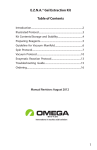
4.4.Analyzer rear panel and connectors
CPP 5Gs
Printer parallel
t
Service
t
ALAN/RS 232 C network
input/output
Logic card fan
Refrigeration compressor
fan
Power switch and
connector
Storage plate for
compressor vibration
mount locking screws
CPP 5Gs
Figure 2: Analyzer rear panel and connectors
Page 18
CPP 5Gs User's Manual
DOCV223A001-F
5.Instrument description
The CPP 5Gs consists of two main parts:
• The user interface.
• The measuring unit and associated electronic and mechanical components.
The user interface is covered in the next paragraph.
The equipment required for cloud- and pour point tests (in direct contact with the sample) strictly complies with
the applicable standard.
The CPP 5Gs includes:
1.A transparent, cylindrical, flat-bottomed glass test tube with a permanent marking for 45 mL volume, which
contains the sample. For cloud point testing, use the test tube with a reflecting bottom.
2.A flat-bottomed brass cylinder providing a leak-tight air bath, known (in compliance with the standard) as the
Jacket, .designed to hold the test tube for heating or cooling purposes.
3.An insulating assembly consisting of a bottom disc and Top ring, providing heat insulation between the test
tube and jacket so that the heat transfer takes place through the air bath, rather than by contact. A measuring
head includes a sample probe which measures sample temperature, a light source and a detection cell for
determining cloud- and pour points. The arrangement of the above three components depends on the type of
measuring head.
4.A Temperature Control System consisting of a heating resistor, a cooling system and a temperature sensor
which measures jacket temperature.
5.A tilting mechanism (consisting of a motor and drive) for tilting the jacket during the pour point test.
Refer to the Part 2 section 8.1 page 2-56
procedure.
DOCV223A001-F
for temperature probe calibration
CPP 5Gs User's Manual
Page 19
CPP 5Gs
6.User interface
6.1.Instrument front panel
The instrument front panel includes the following features:
8 line,
backlight
LCD screen
Key for
activating
menus &
buttons
displayed
Navigator key
Stop, Reset
& Alarm Stop
keys
Numeric key
pad, with "DEL"
and "ENTER"
keys
Text field cursor
key
Figure 3:Analyzer front panel.
6.1.1.LCD screen
The front panel 8-line LCD screen is laid out as follows:
Go up one level
in screen
hierarchy
Button calling for
entry of numeric or
alphanumeric data
Next screen
Previous screen
Menu to be activated using the key
just below (see figure 3)
Figure 4: Screen and menus general layout
"Previous screen" and "Next screen" side keys are provided for navigating through screen hierarchy (see Figure
3). At the bottom of the screen, four keys permit activating the menus displayed on the screen.
6.1.2.Backlight setting
The LCD screen backlight is set by a combination of the ENTER KEY and the high DIRECTION KEY for less
contrast and low DIRECTION KEY for more contrast (refer to the next section).
Note: The intensity of the backlight can change according to the ambient temperature.
Page 20
CPP 5Gs User's Manual
DOCV223A001-F
6.1.3.Control keys
The following three keys are located at the bottom left of the front panel:
TEST
STOP
STOP/TEST: for ending test.
If the LED is on, it means that a test is being run.
RESET: To cancel and go up in screen hierarchy
R
ALARM STOP: interrupt audible alarm signal.
If the LED is ON, this means a problem. Pressing the button will display the
error message.
The remaining area of the front panel is occupied by a numeric keypad with "DEL" and "ENTER" keys.
ENTER key: validates data entry.
ENT
DEL key: deletes characters.
Last, four cursor keys are provided at the bottom left to move through text fields and select characters for data
entry (e.g., sample name).
Direction Keys.
6.2.Welcome screen
When the CPP 5Gs analyzer is switched on, the welcome screen is displayed. If it does not, first check the
backlight settings (see section 6.1.2 on the previous page).
This screen provides information about ISL and two menus offering the choice of language.
I
S
L
www.isl-france.com
ZI Verson
14790 VERSON Tel:(33) 2 31 26 43 00
Fax:(33) 2 31 26 62 93
FRANCE
English
Français
Figure 5 : Welcome screen
The welcome screen remains on until a language is selected. Presse the key corresponding to the language of your
choice. The screen displaying is the screen 1 of the Test/Start menu (see Figure 8 page 1-27).
Note : You can disable the language choice as part of the startup parameters (refer to the Part 2 section 10.1 Power-on parameters: "Start" menu page 2-63). If the choice is locked, press any key on the front panel.
Page intentionally blank.
Page 1-22
CPP 5Gs User's Manual
DOCV223A001-F
Part 1 Using the CPP
5Gs with pre-installed
programs
Page intentionally blank.
Page 1-24
CPP 5Gs User's Manual
DOCV223A001-F
Using the CPP 5Gs with pre-installed programs
1.Introduction
As mentioned above, the versatile nature of the CPP 5Gs is evidenced by its suitability for testing to existing
standards, as well as for customized test programs based on specific calibration data.
This part covers standard cloud and pour point testing. A total of fifteen test programs applicable to the "Cloud",
"Pour" and "Manual" modes are factory-installed by ISL. They are stored in a memory and can be easily updated
by the user (e.g., following a change to a standard) manually or by download from a PC with the “ISL ALAN®
Suite” software specially designed by ISL (via the ALAN® – RS 485 link).
2.First test
This chapter gives a step-by-step description of a standard test using the CPP 5Gs. This description will however
be limited to those menus which are strictly necessary for the proper conduct of the test. Further, it will be assumed
that the operator is familiar with the precautions required for handling the products under test and the cleaning
products.
I.S.L
www.isl-france.com
Tel : 02 31 26 43 00
Fax : 02 31 26 62 93
z.i Verson
14790 Verson
FRANCE
Press any key to continu
S/N :225
(c) ISL, 2000
CPP 5Gs
Software V x.y/x.y
Start
CPP Run
Display
Results
Access
Main level screen
Sample :Fuel R
No :1
Sample :Fuel R
No : 1
Prog: 1 D2500
Op :XY
Prog : 1 D2500
Op :XY
Sample
Start
now
No
Prog.
Status : running
Jack : 20°C
Start
Now
Oper.
ID :Fuel R
Status : running
-11.5°C
Jack: 20°C
18/06/2000 10h30
18/06/2000 10h30
Select an operator name
1:
6:
2:
7:
3:
8:
4:
9:
5:
10:
Sample Number
ABCDEFGHIJKLMNOPQRSTUVWXYZ #&°:[¨^
abcdefghijklmnopqrstuvwxyz
+*-=<>()"%
ok
Delete
ok
Insert.
Sample ID
ABCDEFGHIJKLMNOPQRSTUVWXYZ #&°:[¨^
abcdefghijklmnopqrstuvwxyz
+*-=<>()"%
ok
Delete
ID:Fuel R
-11.5°C
Other
Select a program
No : 1
Insert.
Name: D 2500
Prev.
Next
Unit : °C
Details
Chart 1: Starting a test
DOCV223A001-F
CPP 5Gs User's Manual
Page 1-25
CPP 5Gs
2.1.Preparing sample
Before starting the test, a sample has to be prepared.
Procedure :
1. Choose M00430 test tube with reflecting bottom for a cloud point test, or an M00428 type for a pour point test,
and fill it up to the 45 ml. mark.
2. Inset the cork ring into the positioning jig, then fully inset the test tube. Ring position will thus be as specified
by the standard.
3. Place a cork disc at the bottom of the jacket (the disc should be in good condition for successful testing) and
insert the test tube into the jacket. Select a "cloud point" or "pour point" measuring head (see relevant figure),
introduce it into the test tube previously prepared, then clip it and screw it down onto the jacket. Before
starting test, check that the measuring head selected is connected to the central processing unit.
2.2.Cloud point measuring head
Figure 6: Cloud point measuring head symbol
2.3.Pour point measuring head
Figure 7: Pour point measuring head
Page 1-26
CPP 5Gs User's Manual
DOCV223A001-F
Using the CPP 5Gs with pre-installed programs
2.4.Sample analysis
2.4.1.In cloud mode
Connecting a "Cloud point" head causes the default "cloud" program to become the running program.
Sample:
No :
Prog: 1 D2500
Op :
Sample
Start
Now
No
Figure 8: Screen 1 of CPP/Start menu
Screen 1 of the Test menu includes the following functions:
Sample: button for entering sample ID
No: button for entering sample number
Start Now: test start button
Screen 2 of the CPP menu, accessed through the "Next Screen" button, features the same fields as the previous
screen in its top area, and the following buttons in its top area:
Prog: test program selection button
Oper: test operator ID selection / entry button
Start Now: test start button
Sample:
No :
Prog : 1 D2500
Op :
Prog.
Start
Now
Oper.
Figure 9: Screen 2 of Test/Start menu
The Prog. button permits selecting one of the factory-installed programs. Activating the Prog. menu displays the
following screen:
Select a program
No : 1
ok
Name: D 2500
Delete
Unit : °C
Next
Details
Figure 10: Screen 1 of Program menu
To select the desired program, activate the "Next" or "Previous" button as many times as required. When the
desired program is displayed, activate the OK button. The "Details" button and related menus will be covered in
the "Advanced Utilization" section of this manual.
The Opér. button permits selecting one of the pre-installed operator names. Activating the Opér. menu displays the
following screen:
Figure 11: Screen 1 of Program menu
The CPP 5Gs can store up to 10 operator names. If the desired name is already stored, activate the corresponding
field by means of the front panel DIRECTIONNAL KEYS and press OK., the initial display returns automatically to
the start menu.
To enter a new name, press the Other key. This calls the text entry display (refer to the section 2.6 page 1-31).
DOCV223A001-F
CPP 5Gs User's Manual
Page 1-27
CPP 5Gs
The Other menu allows identifying an operator without using the prerecorded ones, but this new name will not be
stored in the operator list. This function is used to carry out an isolated test. To enter a new operator name in the
memory, refer to the section 6.4 page 2-51).
2.4.2.In "Pour" mode
The analyzer switches to the "Pour" mode as the pour point measuring head is connected. If the connection is not
effective, the instrument will automatically recognize a cloud point test as the default. Thus, proceeding as above
following power up, the following screen will be displayed:
Sample :
No :
Prog: 1 D2500
Op :
°C
Sample
No
EP
Start
Now
Figure 12: Screen 1 of the Pour point test/Start menu
Sample ID, sample No., test start and screen navigation data are the same as in the "cloud" mode. The only change
is the "EP" additional button which permits selecting a pour point temperature, required for starting the test.
Sample :
Prog : 7 D97
No :
Op :
°C
Prog.
Oper.
EP
Start
Now
Figure 13: Screen 2 of pour point test menu
The PROG., OPER. and START NOW buttons are the same as in screen 2 of the CPP/Start menu and have the same
functions, except for the EP button which was already present on screen 1. When starting the test, you will see the
following screen:
Status : running
jack. :-34.2°C
03/07/2000 16h00
ID :
-24.0°C
Tilt
The above screen displays the following data:
•Status: instrument status
•ID: sample ID
•Jack. : Jacket temperature
•Date and time of test
•TILT: this button controls jacket tilt (in a pour point test)
•In bold figures: sample temperature as measured by the probe.
Page 1-28
CPP 5Gs User's Manual
DOCV223A001-F
Using the CPP 5Gs with pre-installed programs
2.4.3.In "Manual" mode
In the "Manual" mode, the operator can conduct tests manually. To operate in this mode, no measuring head
should be connected (no selection of the measuring head possible) and the operator should select factory-installed
"Manual" program # 13. Jacket temperature is selected directly using the numeric keypad. Two screens appear in
succession at the same level:
Sample :
No:
prog :13 manual
Sample
Op :
-9.0°C
No
J.
Stp
Start
Now
No:
Sample
prog :13 manual
Op :
-9.0°C
Program
Oper.
J.
Stp
Start
Now
2.4.4.In "Pour" mode - Rapid Cooling Mode
The operator must select the program N°12, RCM. - Rapid Cooling Method. The pour point temperature is
required to start the test.
Sample :
No :
Prog: 12 RCM
Op :
°C
SmpID
No
Sample :
Prog : 7 D97
Start
Now
No :
Op :
°C
Prog.
Oper.
EP
J.Stp
When the EP (pour point temperature) is entered, the jacket setpoint temperature is automatically calculated and
displayed. It is determined according the EP entered and the cooling profile associated with the rapid cooling
program. Nevertheless, the operator can modify the jacket setpoint temperature manually using the additional
button “J.Stp”.
DOCV223A001-F
CPP 5Gs User's Manual
Page 1-29
CPP 5Gs
2.5.Programmed temperature profiles
The CPP 5Gs features 15 factory-installed programs covering the Cloud point,
Pour point and Manual modes and the Rapid Cooling Method. The following
programs are available:
Cloud point
N°1: D2500. Cloud point test to Standard ASTM D2500 . Temperature in ° C.
N°2: D5771. Cloud point test to Standard ASTM D5771. Temperature in °C.
N°3: ISO 3015. Cloud point test to Standard ISO 3015. Temperature in °C
N°4: IP 129. Cloud point test to Standard QP 129. Temperature in °C
Cloud point test to Standard NF60105.
N°5:
NFT 60105 cloud point.
Temperature in °C
N°6: Cloud point. Standard cloud point test. Temperature in °C
N°14: Cloud (PC). Storage area to be used on a priority basis for downloading
cloud point test programs
Pour point
N°7: D97. Standard pour point test. Temperature in °C
N°8 : D5950. Standard pour point test. Temperature in °C
N°9: ISO 3016. Standard pour point test. Temperature in °C
N°10: IP15. Standard pour point test. Temperature in °C
N°11: NFT 60105 pour point. Standard pour point. Temperature in °C.
N°12 : RCM. Non standard pour point test with rapid cooling method.
Temperature in °C
N°15: Pour (PC). Storage area to be used on a priority basis for downloading
pour point test programs
Manual
N°13: Manual. Pour point or cloud point test carried out manually
Page 1-30
CPP 5Gs User's Manual
DOCV223A001-F
Using the CPP 5Gs with pre-installed programs
2.6.Text entry screen
2.6.1.Text entry
This screen is shown at all levels. It consists of two sections:
The top section (entry section) where the name is entered.
The bottom section, recurrent irrespective of "name" field, which contains a sequence of alphabetic characters
from which the characters to be entered are selected, and the following three buttons: OK, Delete and Insert;
Sample ID
ABCDEFGHIJKLMNOPQRSTUVWXYZ #&°:[¨^
abcdefghijklmnopqrstuvwxyz
+*-=<>()"%
ok
Delete
Insert.
Figure 14: Text entry screen. The field shown is the sample ID.
To enter character, proceed as follows:
Enter characters directly using the numeric keypad.
1. When the entry sceen is displayed, a ablack rectangle blinks over the first letter in the sequence (the letter A).
To select a letter, use the front panel cursor keys. Press appropriate cursor key as many times as required (or
hold key down).
2. When the black rectangle is positioned over the desired character, press the ENTER key of the numeric
keyboard. If the character is not the right one, erase it using the DELETE key.
3. If there is an error in the sequence of characters entered, use the Insert and Delete buttons to correct it.
4. Use the OK button to validate the entry.
Following entry validation using the OK button, the system automatically goes back to the initial screen, i.e.
screen 1 of the CPP/Display menu – see figure 8 on page 20. The same applies to any text entry through the
text entry screen.
2.6.2.Auto edition
To speed up test starting the text entry screen enjoys a semi-automatic input feature: the latest text inputs are stored
in memory so that the operator only needs to enter the first two or three characters for the whole to be displayed.
If the function Auto Edition is activated, the Analyzer proposes a suite when characters are entered according to
prior enters. This function is intended for accelerate test initiating and it can be configured or deactivated (refer to
the Part 2 section 10.1 - Power-on parameters: "Start" menu page 2-63).
DOCV223A001-F
CPP 5Gs User's Manual
Page 1-31
CPP 5Gs
Page intentionally blank.
Page 1-32
CPP 5Gs User's Manual
DOCV223A001-F
Part 2 Advanced
used of the CPP5Gs
Page intentionally blank.
Page 2-34
CPP 5Gs User's Manual
DOCV223A001-F
Advanced utilization of the CPP5Gs
1.Introduction
This section covers the advanced utilization of the CPP 5Gs, with special reference to the setting up of the analyzer
as required by the user. The analyzer's setup is accessible from the main level screen (see next paragraph).
2.Main menu
I.S.L
z.i Verson
14790 Verson
FRANCE
www.isl-france.com
Tel : 02 31 26 43 00
Fax : 02 31 26 62 93
Press a key to continu
CPP 5Gs
Software V x.y/x.y
CPP. run
Start
Display
S/N :225
(c) ISL, 2000
Results
Op :
No
Print
Run env.
Service
Sample :
Prog: 1
D2500
No :
Sample :
Prog: 1
D2500
sample
Access
S/N :225
(c) ISL, 2000
CPP 5Gs
Software V x.y/x.y
Start
Now
prog.
CPP 5Gs
Sofware V x.y/x.y
Quality
S/N :225
(c) ISL, 2000
Setup
No :
Op :
Oper.
Start
Now
Chart 1: Access to main level screen
The main level screen is the highest in the hierarchy. After switching on the analyzer, press any key as indicated
by the welcome screen to access a submenu, from which one must go up one screen level by pressing the
appropriate key.
Chart 1 above shows how this level is accessed.
If the user is at operator level, the available menu ( ) is very simple, and limited to CCP Run, Results and
Access menu.
The user can start and monitor the test.
The user can also view and print results.
If access is at laboratory or service level, the full menu ( + + ) is available.
DOCV223A001-F
CPP 5Gs User's Manual
Page 2-35
CPP 5Gs
CPP 5Gs
Software V x.y/x.y
Start
CPP run
Display
CPP 5Gs
Software V x.y/x.y
Print
Run env.
CPP 5Gs
Software V x.y/x.y
No :225
(c) ISL, 2000
Results
Access
No :225
(c) ISL, 2000
Service
Quality
No :225
(c) ISL, 2000
Setup
Figure 15: The three main level screens with access level 1 or higher
The main level screen shows the following data, from top to bottom and from left to right respectively:
• Instrument designation.
• Instrument serial number.
• Version of control software/communications messages.
Main level menus are the following: CPP Run/Start, CP Run/Display, Results, Access, Print, Environment,
Service, Quality and Setup. These menus are given detailed coverage in the next paragraphs.
However, it should be noted that the CP Test (Start and Display) menu is practically covered in full in 0.
Therefore, in this part we will consider that the access level is level 1 (laboratory level). This level permits access
to test-related parameters, which makes it possible to change those parameters and create customized programs
aimed at specific requirements. Access levels are discussed in the paragraph covering the Setup menu.
Page 2-36
CPP 5Gs User's Manual
DOCV223A001-F
Advanced utilization of the CPP5Gs
3.Access levels and password: "Access" menu
No :225
(c) ISL, 2000
CPP 5Gs
Software V x.y/x.y
Start
CPP run
Display
Results
Access
Access
Current access level is: 1
Labo
Level 1
Service
Level 2
Level 0
If you want to access a function or parameter above levels 0 or 1, the following message is displayed to show
current and required access levels. To enter access codes, use Level 1 and Level 2 buttons. See Setup/Lab menu
for level 1 laboratory access code setup. Also see Setup/Service menu for the definition of level 2 service access
code.
Acess denied
Current access level is : 1 required : 2
Lab
Service
Level1
Level 2
Level 0
Figure 16: "Access denied" message showing that the level is write-protected
Current access level is : 1
Lab
Level 1
Service
Level 2
Level 0
Figure 17: Access menu screen
The main screen of the menu shown above provides access either to a chosen level, or back to level zero. Digital
access codes are entered using the numeric keypad. If the code is valid, the level is accessed following validation
through the Enter key.
DOCV223A001-F
CPP 5Gs User's Manual
Page 2-37
CPP 5Gs
4.Results display: "Results" menu
No :225
(c) ISL, 2000
CPP 5Gs
Software V x.y/x.y
Start
CPP run
Display
Results
Access
Res. : 57/57
Results
Cloud : -26.1°C
Samp: Lv 593-100-15
Prog.: 1 d2500
Print
No: 002
07/07/2000 16h15
Prev.
Next
Transm.
Chart 2: The Results menu
Test results are stored in a dedicated memory. The CPP 5Gs can store up to 99 test results. When the memory is
saturated, the CPP 5Gs will automatically overwrite the first results entered. Results may be uploaded to a PC
through the ALAN® or RS 232 C links. See paragraph 10.5.1 - RS 232 C link configuration: "RS 232 C link
setup" menu page 2-67.
Note : All results are stored. The end of test message indicates if the test has run in normal conditions.
To view the results, the procedure is as follows:
Procedure:
1.Press Results button to display the screen showing all recorded data in the following format:
Res. : 57/57
Samp : Lv 593-10015
Prog.: 1 d2500
Print
Prev.
Cloud: -26.1°C
No: 002
07/07/2000 16h15
Next
Transm
Figure 18: Screen 1 of the Results menu.
• Res. : __/__: result number within the set of results stored in memory.
• Message corresponding to the type of the end of test followed by the test result:
•
•
•
•
1 : « Cloud : _ _ » : normal cloud end of test
2 : « Pour _ _ » : normal pour end of test
3 : « Test stop at : _ _ » : end of test on stop temperature (cloud or pour)
4 : « Test stop: End cooling prof. » : end of test by end of cooling profile reached (cloud or pour)
5 : « Pour not found at : _ _ » : end of test by number of test reached after EP (pour)
6 : « Pour : _ _ at 1st tilt » : end of test by detection of the first tilting (pour)
Samp.: Sample ID
No.: Sample number
Prog.:the program selected for the test.
End of test date and time.
To access the desired results, press PREVIOUS and NEXT" buttons as many times as required. The PRINT button
starts the printing of the result selected.
The TRANSM. Button is used for validating result prior to transmission through RS 232 C link or ALAN®
network
Page 2-38
CPP 5Gs User's Manual
DOCV223A001-F
Advanced utilization of the CPP5Gs
5.Printing: "Printing" menu
No :225
(c) ISL, 2000
CPP 5Gs
Software V x.y/x.y
Start
CPP run
Display
Results
No :225
(c) ISL, 2000
CPP 5Gs
Software V x.y/x.y
Print
Access
Run env.
CPP 5Gs
Software V x.y/x.y
Service Quality
No :225
(c) ISL, 2000
Setup
Print
Printing
Results
Program
Printing
Quality
Stop
Service
Check
Setup
Stop
Chart 3: Printing menu
The CPP 5Gs can print the following data: results, calibration ticket or the parameters of a specific program
according to the printer configuration (see section 10.4 - Printer setup: "Print" menu page 2-66). This requires
connecting the instrument to a printer compatible with the analyzer (40 or 80 column printer using the ESC/p
language).
To start printing, activate main level Printing menu. The following screen is displayed:
Printing
Results
Program
Quality
Stop
Figure 19: Screen 1 of Printing menu
The first screen of the Printing menu features the following menus:
• Results: .for printing results;
• Progr.: for printing a test program;
• Quality: for printing the calibration ticket.
• Stop: to interrupt ongoing printing;.
DOCV223A001-F
CPP 5Gs User's Manual
Page 2-39
CPP 5Gs
The second screen of the Printing menu: looks like this:
Printing
Service
Test.
Setup
Stop
Figure 20: Screen 2 of Printing menu
Screen 2 features the following menus:
• Service: for printing data such as ongoing measurement values (sample and jacket temperatures).
• Test: for checking printer link.
• Setup: for setting printing parameters.
• Stop: to interrupt ongoing printing.
5.1.Printing results
The CPP 5Gs can print any test result, or all the previous test results, with or without a program (see Appendix A
section 1 - 80-column result print page 75).
Results can be printed at any of two levels:
1. From the Results menu, by activating Printing. At this level, select the desired result using the Previous or
Next buttons, then print.
2. From the Printing menu (see Figure 19: Screen 1 of Printing menu page 2-39). Upon activation of the
Results menu, the following screen is displayed:
Results printing
One Res
All
Figure 21 : Screen 1, Results menu (from Printing menu)
This screen permits the printing:
• Of any result. Activating the ONE RES button displays the screen of Figure 18: Screen 1 of the Results menu.
page 2-38. At this level, the printing mode is the one mentioned in 1) of this paragraph. It should be noted that
a number of printing options are available, among which the printing of the test program used (see section 5.6 Printer setup page 2-42).
• Of all the results stored in memory can also be printed. In this case, test programs will not be printed.
Note: Test results are printed with the end of test message indicating if the test has run in normal conditions.
Types of the end of test:
1 : « Cloud : _ _ » : normal cloud end of test
2 : « Pour _ _ » : normal pour end of test
3 : « Test stop at : _ _ » : end of test on stop temperature (cloud or pour)
4 : « Test stop - End cooling profile » : end of test by end of cooling profile reached (cloud or pour)
5 : « Pour not found at : _ _ » : end of test by number of test reached after EP (pour)
6 : « Pour : _ _ at 1st tilt » : end of test by detection of the first tilting (pour)
Page 2-40
CPP 5Gs User's Manual
DOCV223A001-F
Advanced utilization of the CPP5Gs
5.2.Printing test program parameters
The CPP 5Gs will also print the parameters of the test program stored in memory. Activating the Programs menu
will display the following screen which permits selecting a test program.
Printing program No :1
Name : D2500
Unit:°C
Print
Next
Figure 22: Program menu screen (Printing menu).
Pressing the Print button will start the printing of the program shown on the screen. To print another program,
press next button to display the desired program, then the print button.
5.3. Printing calibration ticket
The calibration ticket can also be printed. This is done by activating the Quality menu, :thereby displaying the
following screen:
Quality printing
Calibration
Ticket
Internal param.
40/80
80 col
Figure 23: Quality menu screen (Printing menu)
The Internal Parameters printing button provides the following two options:
• Taking printer configuration into account (40/80 button).
• Always printing in 80-col. Format (80 col. button) irrespective of printer configuration.
5.4.Printing ongoing test results
Measurement results can be printed using the measurement display screen or the Measure. button of the next
screen:
Service Printing
Measure
Regul.
Internal Param.
40/80
80 col.
Figure 24: Service printing.
To access the contents of the Régul menu, authorization to access level 2 (Service) is required. This menu permits
collecting and transmitting to a printer or other peripheral (e.g. a PC) regulation data relating to the following
components (see Appendix A section 2 - 80-column internal parameter printout page 76):
• Jacket probe
DOCV223A001-F
CPP 5Gs User's Manual
Page 2-41
CPP 5Gs
5.5.Printing test
The Test button (see Figure 20: Screen 2 of Printing menu page 2-40) permits printing a few lines to check the
printer
CPP 5Gs link (see Appendix A section 5 - Printing test page 77). Further, this provides a check on the
print quality of certain special characters (e.g., the "degree" symbol), which may have been poorly printed due to
incorrect setup.
5.6.Printer setup
To set up the printer, use the Printer Setup menu (see section 10.4 - Printer setup: "Print" menu page 2-66). The
Printing menu in Setup can also be used for printer setup
Activating Setup (in Printing menu) permits displaying the following screens.
Screen
Purpose of menu
(Setup menu).
(from left to right and from top to bottom
respectively).
Printer setup
Automatic printing: automatic result Yes/No
printing at end of test (if printer is
connected to analyzer
Test printer test printing.
Printer setup
Yes
Automatic result
Printing
Field
entry
Check
Screen 1, Setup menu
Next sccreen
Results printing with:
Program: print program used for the Yes/No
test.
Printer setup
Results printing with:
Yes
Program
Screen2, Setup menu
Printer setup
40 columns
18
248
2
Printer
Select
Red
code
Degree
code
Line feed
Screen 3 menu Config.
Next screen
Printer Select : selection of a printer 40/80 col.
compatible with the analyzer (using printer ESC/P
ESC/P
language) compatible (see
printer doc.)
See printer doc.
Red code : code for printing in red
Degree code : ASCII code designating See printer doc.
"degree" code (see printer doc.).
Line feeds : number of line feeds after 0 to 5 or form
feed
printing.
For example::
Configuration of a CITIZEN® 40-column printer:
40
18
91
2
Configuration of an EPSON® 80-column printer
80
0
248
2
However, it will be necessary to refer to the printer manual for the exact printer setup.
Table 1: Setup menu screens.
Page 2-42
CPP 5Gs User's Manual
DOCV223A001-F
Advanced utilization of the CPP5Gs
6.Test setting: the "Run environment" menu
S/N :225
(c) ISL, 2000
CPP 5Gs
Software V x.y/x.y
Start
CPP run
Display
Results
S/N :225
(c) ISL, 2000
CPP 5Gs
Software V x.y/x.y
Access
Print
Rn env.
Service
CPP 5Gs
Software V x.y/x.y
Quality
S/N :225
(c) ISL, 2000
Setup
Run env.
Run environment programming
Select an operator name
Progr.
Oper.
Oper.
1:
2:
3:
4:
5:
6:
7:
8:
9:
10 :
OK
Other
Program No: 1
Name : D2500
Prev.
Unit :°C
Next
Details
Program No 1
Program No: 1
D2500
°C
Cloud
Name
Unit
Type of
analysis
Program No: 1
yes
Rounded
temp
Program No: 1
-150.0°C
100
Detection
level
Alarm
Auto
Test mode
Program No: 1
-150.0°C
Stop
1: D2500
Cooling Profile
Chart 4: The Environ. menu
6.1.Test program - cloud method
A test program consists of the following:
• Test parameters.
• A cooling profile.
The CPP 5Gs features the following 6 factory-installed cloud point programs:
• 1. D2500
• 2. D5771
• 3. ISO 3015
• 4. IP 129
• 5. NF 60105
• 6. Cloud
In addition to the above, another program is provided for receiving programs transmitted by the PC through the
ALAN® network:
• 14. Cloud (PC)
While all parameters in a program are visible, modifications are subject to level 1 (Laboratory) access
authorization. To access program parameters and associated temperature profiles, proceed as follows:
DOCV223A001-F
CPP 5Gs User's Manual
Page 2-43
CPP 5Gs
Procedure:
Activate Environ. menu in main level screen 2 (see Chart 4 on the previous page). The following screen is
displayed:
Program n°: 1
D2500
Oper.
Oper.
Progr.
Figure 25: Screen 1 of Program menu
Activate Progr. menu of the Environ. menu. The following screen is displayed:
Program No: 1
Name : D2500
Prev.
Unit :°C
Next
Details
Figure 26: Screen 1 of Program menu
The Next and Previous buttons permit scrolling to select a factory-installed program.
On Figure 26 above, No. 1 program has been selected. To view program parameters, press Details button. This
will permit the following screens to be displayed:
Screen
Purpose of menu
(Program menu).
(From left to right and from top to bottom
respectively).
Program No: 1
D2500
°C
Name
Unit
Field
entry
Current program is program No 1
Name: name of program selected . In this
case, name is D2500
Unit: selection of temperature unit.
Temperature is measured in °C.
°C/°F
Screen 2, Program menu.
Next screen..
Program No: 1
Cloud
Auto
Type of
Analysis
Test mode
Type of analysis: type of test selected: Cloud/ Pour
Cloud
Auto/
Manual
Test mode: select auto or manual
Screen 3,. Program menu.
Next screen..
Rounded temperature
Program No: 1
Yes
Rounded
Temp
100
Yes/No
Detection levels:
Default, Cloud: 100
Detection
level
Screen 4 Program menu.
Next screen..
Page 2-44
CPP 5Gs User's Manual
DOCV223A001-F
Advanced utilization of the CPP5Gs
Alarm: Alarm is set off when sample is at
desired temperature
Program No: 1
-150.0°C
Alarm
-150.0°C
Stop: Test stops when sample is at
temperature
Stop
Screen 5, Program menu.
Next screen..
Cooling profile: choose cooling profile
Program No: 1
1: D2500
Cooling Profile
Screen 6, Program menu.
Table 2: Progr. menu screens – cloud method
Without the required authorization (password), it will not be possible to change the field
entries in Program menu screens. This will require access level 1 authorization.
The Cooling Profile menu gives access to another screen level to view and set up cooling profiles. Each factoryinstalled program can be associated with a fully customized cooling profile. To view a cooling profile, proceed as
explained below. It should however be remembered that changing profile values is subject to level 1 access
authorization.
DOCV223A001-F
CPP 5Gs User's Manual
Page 2-45
CPP 5Gs
6.2.Test program - pour method
Le CPP5Gs features the following seven factory-installed pour point test programs:
• 7.D 97
• 8.D 5950
• 9.ISO 3016
• 10.IP 15
• 11. NFT-60-105
• 12. RCM (Rapid Cooling Method)
• 15. Pour (PC)
Procedure
First, activate the Program menu of the main level screen 2 (see Chart 4: The Environ. menu page 2-43) and
select a pour point program using the Previous and Next buttons. Then, press Details button to access the
following screens:
Screens
(Program
Purpose of menu
menu).
(From left to right and from top to bottom
respectively).
The program selected is program No. 7
Name: name of program selected
Unit: selection of temperature unit. °C / °F
Temperature is measured in °C in this
case.
Program No: 7
°C
D97
Name
Field
entry
Unit
Screen 2, Progr. menu
Next screen
Cloud/Pour
Type of analysis : type of test selected.
Test mode: select "auto" or "manual". In
"manual" mode, no measuring head
should be connected
Program No: 7
Pour
Auto
Type of
analysis
Test mode
Screen 3, Progr. menu
Next screen
First test temperature: Used to set the
temperature chosen for the first tiling
action with respect to the estimated pour
°C / °F
point.
Test Frequency: Sets the interval
between tilting actions at first test
temperature.
Program No: 7
at EP
+ 9°C
3.0°C
First test
temperature
Test
frequency
Screen 4, Progr. menu
Particular case:
At test starting, if the sample temperature is lower than the temperature of the first tilting test (Ep + 9°C), the first test will
be performed at : first test = temperature of the first test (Ep + 9°C) – (x test frequency)
Example :
Tilting temperature
T (°C)
60
55
50
45
40
55
52
For a sample for which the Ep is 46°C, if
Sample T° = 50°C, the first test is
performed at 49 °C.
49
46
t (s)
Next screen
Page 2-46
CPP 5Gs User's Manual
DOCV223A001-F
Advanced utilization of the CPP5Gs
Program No: 7
No
350
Stop 3 tests
after EP
Level of
detection
Stop 3 tests after EP: If this option is Yes / No
selected, testing will stop after the third
unsuccessful tilting following the EP.
0 / 999
Level of detection: The change (in
number of points) required at the
optical receiver to detect pour point.
A value of 350 will detect most
products.
Screen 5, Progr. menu
Next screen
Program No: 7
-150.0°C
-150.0°C
Alarm
Stop
Alarm:The operator can select an alarm
set-off temperature.
A default
temperature of -150° C is included in the
program.
StopA specific value of end-of-test
temperature may be entered.
The
programmed default temperature is –150°
C.
Screen 6, Progr. menu
Next screen
Cooling profile:
selection.
Program No: 7
Cooling
profile
1: D97
Cooling profile
Screen 7, Progr. menu
Table 3: Progr. menu screens – pour method
DOCV223A001-F
CPP 5Gs User's Manual
Page 2-47
CPP 5Gs
6.3.Cooling profile: "Cooling profile" menu
A cooling profile consists of several stages. Each stage is defined by the following statements:
• Type (which cannot be modified from test station).
• Set point.
• Condition for moving to next stage.
Only those stages which have been programmed can be modified. To customize profiles, go back to PC software.
When the "Cooling profile" is activated, the following screen is displayed:
Cooling Profile No: 1
Name : D2500
Prev.
OK
Unit :°C
Next
Details
Figure 27: Screen1 of Cooling menu – cloud method
This screen permits selecting a cooling profile from the 15 factory-installed ones, by pressing the Next button as
many times as necessary and OK to validate (subject to the necessary authorizations). In the factory set-up, profile
1 is associated with program 1, profile 2 with program 2, etc. The Details menu permits viewing the parameters at
each profile stage.
6.3.1.Cooling profile – cloud method
Press the Details key of the cooling profile selection menu in cloud method (Figure 29 above):
Screens
Purpose of menu
(Cooling profile
menu.
Field entry
(From left to right and from top to bottom
respectively).
Cooling profile No: 1
D2500
°C
Name
Unit
Cooling profile is profile No. 1
(permanent field).
Name: profile name selection
Unit: temperature unit selection. Unit °C/°F
should be consistent with that in
associated program.
Screen 2, Cooling profile menu
Next screen
Cooling profile No: 1
Step : 1
Sample preheating
at 45.0°C
Set point
for
0 min.
Stage 1
Sample preheating
Set point: sample heating temperature
Limit: heating time in minutes after
reaching set point.
0 min means no heating.
Limit
Screen 3, Cooling Profile menu
Next screen
Page 2-48
CPP 5Gs User's Manual
DOCV223A001-F
Advanced utilization of the CPP5Gs
Cooling Profile No: 1
Step : 2
Jacket level
at 6.0
Set point
Until sample
<°C 27. 0
Stage 2
First cooling stage of cloud test point.
Set point: jacket cooling stage set point.
Limit: sample temperature limit before
switching to next jacket cooling stage.
Limit
Screen 4, Cooling profile menu
Nine screens identical to the above are displayed in succession, representing the jacket cooling stages provided for in
the standards listed in paragraph 2.5 - Programmed temperature profiles page 1-30.
Next screen
Cooling Profile No: 1
Jacket temperature
25.0°C
Step :12
Final
Heating
Step 12
Set: point: jacket temperature set point
for new test
Set point
Screen 14, Cooling Profile menu
Next screen
Step 13
End-of-profile screen - Common to all
profiles.
Cooling Profile No: 1
Step 13
End of profile
Screen 15, Cooling Profile menu
Table 4: Cooling Profile – cloud method
6.3.2.Cooling profile – pour method
Press the Details key of the cooling profile selection menu in pour method (after having activated the cooling
menu, screen 7 of the progr. menu, Table 3 page 2-47), the following screen is displayed:
Screens
Purpose of menu
(Cooling profile
menu.
Cooling profile No: 7
D97
Name
Field entry
(From left to right and from top to bottom
respectively).
°C
Cooling profile is profile No. 7
(permanent field).
Name: profile name selection
Unit: temperature unit selection. Unit °C/°F
should be consistent with that in
associated program.
Unit
Screen 2, Cooling menu
Next screen
Cooling profile No: 7
Step : 1
Sample preheating
at 45.0°C
Set point
for
0 min.
Stage 1
Sample preheating
Set point: sample heating temperature
Limit: heating time in minutes after
reaching set point.
0 min means no heating.
Limit
Screen 3, Cooling menu
Next screen
DOCV223A001-F
CPP 5Gs User's Manual
Page 2-49
CPP 5Gs
Cooling Profile No: 7
Step : 2
then
step 3
If EP > -33°C
else
step 4
Set point
Stage 2
Set point: presumed pour end point
temperature value.
If the pour end point presumed
temperature is above –33°C (EP>-33°C),
program step 3 is carried out, then step 5.
Otherwise, program will carry out step 4
then step 5.
Screen 4, Cooling menu
Next screen
Cooling Profile No: 7
Step : 3
Jacket level
at 24.0°C
Set point
Until sample
< 27. 0°C
Limit
Stage 3
First cooling stage of pour point test for
EP> -33°C.
Set point: jacket cooling temperature set
point.
Limit: sample temperature limit before
switching to next jacket cooling stage,
step 5 (following 7 screen).
Screen 5, Cooling menu
Next screen
Cooling Profile No: 7
Step : 4
Jacket level
at 6.0°C
Set point
Until sample
< 15. 0°C
Limit
Stage 4
First cooling stage of pour point test for
EP[ -33°C.
Set point: jacket cooling temperature set
point.
Limit: sample temperature limit before
switching to next jacket cooling stage,
step 5 (following 7 screen).
Screen 6, Cooling menu
Next screen
Cooling Profile No: 7
Step : 5
Jacket level
at 0.0°C
Set point
Until sample
< 9. 0°C
Stage 4
Second cooling stage of pour point test.
Set point: jacket cooling temperature set
point.
Limit: sample temperature limit before
switching to next jacket cooling stage.
Limit
Screen 7, Cooling menu
Four screens identical to the above are displayed in succession, representing the jacket cooling stages provided for in
the standards listed in paragraph 2.5 - Programmed temperature profiles page 1-30.
Next screen
Cooling Profile No: 7
Step :13
Final
Heating
Jacket temperature
25.0°C
Step 13
Set: point: jacket temperature set point
for new test
Set point
Screen 15, Cooling Profile menu
Next screen
Step 14
End-of-profile screen - Common to all
profiles.
Cooling Profile No: 7
Step 14
End of profile
Screen 16, Cooling Profile menu
Table 5: Cooling Profile – pour method
Page 2-50
CPP 5Gs User's Manual
DOCV223A001-F
Advanced utilization of the CPP5Gs
6.4.Operator name list
Press the Operator key in the Run Environment menu to display the prestored list of operator names (up to 10), the
following screen is displayed:
Select an operator
1:
2:
3:
4:
5:
6:
7:
8:
9:
10 :
Print
Details
Figure 28 : Run Environment menu screen - List of operator names
The Operator menu screen contains the following menus:
Print : to print the list of operator names
Details : to get to the operator name setup menu
The Print menu lets you print out the list of operator names. Press the Print key to start printing immediately.
Select a prestored operator name if you wish to modify it or select a free field if you wish to store a new operator
name. Press the Details key, the « Operator » text entry screen is displayed. Enter the name (refer to the section
2.6.1 page 1-31 for further details on using the text entry screen) then press OK to confirm.
DOCV223A001-F
CPP 5Gs User's Manual
Page 2-51
CPP 5Gs
7.Measurements and diagnostics: "Service" menu
CPP 5Gs
Softwarel V x.y/x.y
CPP run
Display
Start
S/N :225
(c) ISL, 2000
Resuls.
Access
CPP 5Gs
Software V x.y/x.y
Print
S/N :225
(c) ISL, 2000
S/N :225
(c) ISL, 2000
CPP 5Gs
Software V x.y/x.y
Run env Service Quality
Setup
Service
Service
Measurements
Diagnostics
Chart 2: "Service" menu
The Service menu is largely devoted to servicing. It permits:
• Displaying measurement data.
• Performing diagnostics on Analyzer major components.
7.1.Service menu
Activating the Service menu displays the following screen:
Service
Measures
Diagnostics
Figure 29: Service menu screen
The Measurements menu (in Service menu) gives access to the following data, distributed over two screens:
Screens
Purpose of menu
(Measurements menu)
Samp.: -7.0°C 125.2
125.05
Jack. :-19.2°C
Cooling Unit :78
00001011
9,4%
Print
Screen 1, Measurements menu.
(From left to right and from top to bottom respectively)
A/D : FFFF
A/D : 0
Heat. : 0
0.0%
Samp. : sample temperature(°C).
resistance sample probe ( ).
Jack. : jacket temperature (°C)
jacket probe resistance. ( ).
A/D :analog/digital conversion
Cooling unit : cooling, percent.
Heat: heating, percent.
Print: print both screens.
Next screen
Page 2-52
CPP 5Gs User's Manual
DOCV223A001-F
Advanced utilization of the CPP5Gs
Optical detector
Receiver : 0 pts
Emitter : 0 pts
Motor : 0 pts
Optical detector
Receiver: number of points received.
Emitte: number of points transmitted.
Motor: Number of points fed to motor
Print
Screen 2, Measurements menu.
Table 1: Measurements menu screens.
7.2.Diagnostic menu
Access to the Diagnostics menu is subject to level 2 access authorization (service).
Screens
Purpose of menu
(Diagnostics menu).
(From left to right and from top to bottom).
Samp.: -7.0°C
Jack. :-19.2°C
125.2
125.05
A/D : FFFF
A/D : 0
Cooling unit :0
00000011
0.0%
0.0%
C. unit
Cool.
Heat
Field
entry
Top of screen: see Table 4.
C. unit: access to the cooling diagnostic
menu (see next section).
Cool:. :enter cooling percent.
Note: The analyzer may lower the power
entered to limit vibrations
Heat: enter heating percent
Screen 1, Diagnostics menu
Next screen
Optical detector
Receiver :
0 pts
Emitter :
0 pts
Auto.
Motor : 0 pts
Emit.
Screen 2, Diagnostics menu
Optical detector.
Emitter: number of points emitted.
0 pts: no light emission.
4095 pts: maximum light emission
Receiver: number of points received:
0 pts :no light received.
4095 pts : maximal light received
Auto: emitter servo-control to obtain a
given number of points at
receiver( 2000 pts)
Emit: enter manually the number of
points to be emitted.
0
4095 pts
(max.
emission)
0
4095 pts
Next screen
Jacket tilting
Ensure that test tube is em pty
M otor :
0 pts
00100001
Off
Motor points: conversion of points to
volts to specify drive power
00 10000 1
Bit 0 = 1 : vertical position
M anual
Bit 1 = 1 : horizontal position
Screen 3, Diagnostics menu
Bit 4 = 1: Cloud head connected
Bit 5 = 1 : Pour head connected
Before controlling motor manually, disconnect the measuring head and verify that the tube is empty.
Endurance
Cycle:
Off
Cycle
0
Step:0
Count: 0s
Tilt: 0
Am b: 24.2
Jack: 22.6
Cycle: Starting an endurance test for
cooling unit
Screen 4, Diagnostics menu
Table 2: Diagnostic menu screens
DOCV223A001-F
CPP 5Gs User's Manual
Page 2-53
CPP 5Gs
7.3.Cooling unit diagnostic
Before starting cooling unit diagnostic, remove test tube and place covering head on
jacket. Diagnostic procedure may take up to 80 minutes.
Screens
Purpose of menu
(Cooling unit menu)
(From left to right and from top to bottom respectively)
Cool: diagnostic temperature
Start : diagnostic initialization
Print: print diagnostic data
Cooling unit diagnostic
Remove tube
Place head on jacket, then press start
100%
(Duration : 80 min maxi)
Cool.
Start
Print
Cooling Unit Diagnostic screen (Diagnostic menu)
The cooling unit diagnostic is carried out in three stages:
1.
2.
3.
Initialization: heating to 40° C and temperature regulation for 3 min.
Cooling: cooling to –110° C. During this phase, the program records the data relating to certain significant
temperatures (time to reach significant temperature, number of points actually applied.
Heating: return to room temperature.
The Print. button permits printing cooling unit characteristic data (in addition to data recorded in phase 2 above),
which may be sent to ISL's Customer Service Dept. for an assessment of cooling unit condition.
Page 2-54
CPP 5Gs User's Manual
DOCV223A001-F
Advanced utilization of the CPP5Gs
8.Calibration: "Quality" menu
CPP 5Gs
Software V x.y/x.y
CPP run
Strat
Display
S/N :225
(c) ISL, 2000
Results
Access
S/N :225
(c) ISL, 2000
CPP 5Gs
Software V x.y/x.y
Print Run env Service
Quality
S/N :225
(c) ISL, 2000
CPP 5Gs
Software V x.y/x.y
Setup
Quality
Quality
Quality
Samp. T.
calib.
Cloud
Table
Pour
Table
Jack.T.
Check.
Jack.T.
Calib.
Calib. ticket
printing
Chart 6 : Quality menu
Calibration of CPP 5Gs measuring instrumentation is occasionally required. Although calibration intervals are the
user's decision, it is recommended to calibrate all measuring instruments at least once yearly. The Quality menu
comprises a series of sub-menus, grouped in the following screen, which covers the following calibration steps:
Quality
Samp. T.
Calib.
Quality
Cloud
Table
Pour
Table
Jack. T.
Calib
Jack.T.
Check.
Calib. ticket
printing
Figure 30: Quality menu screens
• "Sample T calib": calibration of sample temperature measurement.
• "Cloud Table": correction table for the sample temperature probe in "cloud" mode.
• "Pour Table": correction table for the sample temperature probe in "pour" mode.
• "Jack T calib": calibration of jacket temperature measurement.
• “Jack.T.Check”: checking procedure for jacket temperature measurement
The Calib. Ticket.Printing menu can be used for printing calibration data (refer to the Appendix A section 3 - 80column calibration ticket printout page 77 for a printing example).
DOCV223A001-F
CPP 5Gs User's Manual
Page 2-55
CPP 5Gs
8.1.Sample temperature measurement calibration: "Sample Temp Calib."
menu
Sample temperature measurement is calibrated using the "Sample Temp. Calib." menu. The calibration procedure
is as follows:
Procedure:
1.
2.
3.
4.
Disconnect probe DIN connector.
Plug probe simulator connector into probe socket (see list of spares).
Activate "Sample Temp. calib." menu.
Follow the guidance provided by the following screens:
Screens
Purpose
(Sample Temp. alib. menu).
(From left to right and from top to bottom
respectively).
Sample Temp. measurement calibration
Performed : 24/07/2000 next: 24/07/2001
No
365 days
Frequency
Test refusal
of
menus Field
entry
365
Frequency:
calibration intervals. 0
0 days means there is no check on the days
next calibration date being past.
Yes /No
Test refusal: start test. Refused when
missing the date set for the next
calibration.
Screen 3, Sample Temp. calib. menu
Next screen
Sample Temp. measurement calibration
Operator
Operator: name of operator performing Chain list
the calibration.
Calib. reference: calibration reference Chain list
data.
Calib.
reference
Screen 2, Sample Temp. calib. menu.
Next screen
Sample Temp. measurement calibration
Caution: Be sure the PT100 simulator is
connected, then press (Continue)
End
End: cancel calibration. Return to screen 1 of
"Sample Temp. calib." menu.
Continue: when calibration is underway, it cannot be
cancelled. Front panel keys are inoperative.
Continue
Screen 3, Sample Temp. calib. menu
Next screen
Sample Temp. measurement calibration
Position simulator on -50°C/-58°F
80.310
Set simulator thumbwheel to
-50°C/-58°F.
Resistor value: Enter resistor value in Ohms if
required.
Resistor value
Screen 4, Sample Temp. calib. menu
Next screen
Sample Temp. measurement calibration
A/D :88D9
Resistor value: 83.310
When display is practically stable (the first three
characters of the A/D conversation are stable), press
OK to validate.
Check when the measure is stable
OK
Screen 5, Sample Temp. calib. menu
Proceed as above, setting simulator thumbwheel to +50° C/1322° F. When operation is completed, the instrument
displays screen 1 of the Quality menu
Table 3: Sample Temp. calib. menu screens
Page 2-56
CPP 5Gs User's Manual
DOCV223A001-F
Advanced utilization of the CPP5Gs
8.2.Probe correction chart: "Cloud table" and "Pour table" menus
The "Cloud table" and "Pour table" permit entering a correction table for the sample temperature probe according
to the detection point mode selected. The sample temperature displayed is as corrected on the basis of the table (at
standstill, during test and during calibration).
The sample probe is a Pt 100 platinum probe as per standard IEC 51-Class A. It is delivered
with an ISL Quality Certificate showing the temperature discrepancy at 40° C (discrepancy
= Value – Reference t°) ° C).
When a "Cloud table" or "Pour table" menu is activated, the following menu is displayed:
Sample probe correction
Correction probe value: (Reference)
°C
Name
Unit
Figure31: Screen 1 of "Cloud Table" menu
This screen permits entering correction table ID and selecting the table temperature unit. Corrections can be
entered through a series of screens similar to the above (correction = probe reading – reference value) in a
temperature range from –150° C (-238° F) to +60° C (140° F) (with a 10° C increment):
Sample probe corrcetion
Correction probe value: (Reference)
0.0
0.0
0.0
0.00
-150°C
-140°C
-130°C
-120°C
Figure 32: Screen 2 of Sample Probe Correction menu.
8.3.Jacket temperature measurement calibration:
menu »
"Jacket Temp. Calib."
It is preferable to calibrate jacket temperature after sample temperature (see previous paragraph). There are two
ways to calibrate jacket temperature:
1. Automatically, using the sample probe.
2. Manually, using a calibrated thermometer.
Actually, the CPP 5Gs computes the difference between the temperature as shown by the sample probe and the
jacket temperature. If the latter is too high, the instrument will consider calibration to be bawd on an external
calibrated thermometer. In that case, it will wait until a reference value has been entered before it moves to the next
stage.
DOCV223A001-F
CPP 5Gs User's Manual
Page 2-57
CPP 5Gs
Procedure:
Follow the indications of the screens shown in the following table:
Screens
Purpose
(Jacket Temp. calib. menu).
(From left to right and from top to bottom respectively).
Jacket Temp. measurement calibration
<Name>
of
menu
Operator: name of the operator performing the jacket
temperature probe calibration.
Calib. Reference: calibration operation reference.
<Ref.>
Calib
Reference
Operator
Screen 1, Jacket Temp. Calib. menu
Next screen
Jacket Temp. measurement calibration
Fill the jacket up to the mark and
immerse the reference probe
Set Pt:10/-34°C
Fill jacket with methanol up to the mark visible on the
inner wall. Select the two calibration temperatures.
Set
point:
10/-34°C
or
Set point: -34/-51°C : cooling stages
Continue: next step in the procedure.
Continue
Screen 2, Jacket Temp. Calib. menu
Next screen
Jacket calibration in progress
Set point: 10.0°C Waiting : 6 mn
Tmp jack. : 10.1°C Sample :12.7°C
Cancel
Set point: select the two calibration points
Waiting: waiting time for jacket to cool off
Tmp jaq. : jacket temperature
Sample: sample temperature.
Cancel: stop calibration procedure (this is the only
way to stop the operation)
Screen 3, Jacket Temp. Calib. menu
Next screen
Jacket Temp. measurement calibration
Jacket : 10.0°C Samp. Probe :10.0°C
Duration : 10 mn
°C
Cancel
Reference temp.
Screen 4 Jacket Temp. Calib. menu
Jacket: jacket temperature.
Samp. probe: sample temperature
Duration: time for sample temperature to stabilize.
During that time, the operator may enter the reference
temperature ("Reference temp." field). If the sample
probe is used, the CPP 5Gs will automatically set the
sample temperature shown on the screen.
Cancel: stop calibration procedure
Reference temp.: sample temperature
-as read off thermometer.
–or as measured by probe .
Proceed as above for the second stage (-34.0° C)
Table 4: Jack. Temp. Calib. menu screens
On completion of the procedure, the CPP 5Gs heats the jacket to +25°C
Page 2-58
CPP 5Gs User's Manual
DOCV223A001-F
Advanced utilization of the CPP5Gs
8.4.Jacket temperature measurement checking: the “Jack.T.Check." menu
Jacket temperature measurement is checking manually using a reference thermometer or probe.
Procedure:
Follow the indications of the screens shown in the following table:
Screens
Purpose of menu
(Jacket T. Check. menu).
(From left to right and from top to bottom respectively).
Jacket Temp. measurement calibration
Fill the jacket up to the mark and
immerse the reference probe
Continue: start the checking procedure after having
filled the jacket and positioned the reference probe or
thermometer.
Continue
Screen 1, Jacket T. Check. menu
Next screen
Jacket Temp. measurement calibration
Jacket Set point
Jacket Set point: enter the jacket set point
temperature.
Start: the CPP 5Gs controls the jacket cooling up to
the set point temperature.
Start
Screen 2, Jacket T. Check. menu
Next screen
Jacket Temp. measurement calibration
Jacket: 25.2°C
Sample: 26.0°C
Set point: -10°C
Waiting: 15 min
Cancel:
stop the jacket temperature checking
procedure. Go back to the main level of the Quality
menu (Figure 30 page 2-55).
Cancel
Screen 3, Jacket T. Check. menu
Next screen
Jacket Temp. measurement calibration
Wait for the jacket reheating
before draining it.
Jacket: 41.1°C
OK: Go back to the main menu level after having
drained the jacket and removed the reference probe.
OK
Screen 4 Jacket T. Check. menu
Table 5: Jack. Temp. Calib. menu screens
If the jacket set point temperature entered does not correspond to the temperature measured by the reference
thermometer or probe, carry out the jacket temperature measurement circuit calibration (refer to the section 8.3
page 2-57).
DOCV223A001-F
CPP 5Gs User's Manual
Page 2-59
CPP 5Gs
9.Alarm treatment
9.1.Types of alarm
9.1.1.Failure alarms
The failure alarms warn the operator in the event of a malfunction.
Failure alarm detection has at least one of the following consequences:
• A test cannot be started,
• A test in progress is stopped,
These failures set off a continuous audio alarm and the red LED of the ALARM STOP key lights up on the keypad
(see the section 6.1.3 page 1-21). Press the ALARM STOP key to display the alarm message and acknowledge it or
not. The red LED stays on for as long as the failure persists, even if the alarm has been acknowledged.
The failure alarms and the corresponding message are shown in the section 0 page 2-64.
The limits of certain of these failure alarms can be set (refer to the section 10.2 - Alarms setup: "Alarms setup"
menu page 2-63).
9.1.2.Warning alarms
The warning alarms warn the operator of an expected event: “ End of test (cloud and pour)” for example.
They are accompanied as for them by a discontinuous audio alarm (the signal modulation width is adjustable; refer
to the section 10.2 - Alarms setup: "Alarms setup" menu page 2-63). The red LED on the ALARM STOP key lights
up on the keypad. It goes off when the alarm is acknowledged.
The warning alarms and the corresponding message are shown in the section 10.2.3 page2-65.
9.2.Displaying alarms, stopping the buzzer
When an alarm is triggered, press the ALARM STOP key to display the cause. The following screen is displayed:
No alarm to signal
Exit
Acquit
Review
Figure 33: Alarms displaying screen
The alarms screen display contains the following menus and buttons:
Exit: to go back to the previous screen without acquitting the alarm.
Acquit.: to acquit the alarm and to go back to the previous screen.
Press the Acquit key to stop the buzzer and return to the previous screen. Note that the red LED on the ALARM
STOP key stays on for as long as the default persists, even if the alarm has been acknowledged.
Review: to display the alarm historical.
9.3.Alarm processing
Certain alarm cases present a danger. This is why most default settings switch the Analyzer into idle status, thus the
cooling unit is cut out.
However, this is not to say that this type of apparatus is hazard-free or that if the Analyzer fails to go into idle status
the operator and/or Analyzer are not in danger. It is important always to check what is going on whenever an alarm
is triggered.
Attention! Generally when the alarm buzzer is triggered, the operator must display the cause
and ensure that everything is working correctly.
For example, owing to a faulty component an alarm that normally should place the apparatus in idle mode fails to do
so. In that case, the operator must intervene by switching off the analyzer.
Page 2-60
CPP 5Gs User's Manual
DOCV223A001-F
Advanced utilization of the CPP5Gs
9.4.Alarm historical
The CPP 5Gs can register up to 16 alarm messages.
Activate the Review menu from the alarm displaying screen (see Figure 33 page 2-60), the following screens
appear:
Displays
Meaning of different menus
(Review menu of the Alarm displaying screen)
(Going from left to right and from top to bottom).
Faults review
Date
Time
Message registered
Exit
Print
Field values
Faults review : permanent field
Exit: To go back to the alarms displaying screen
Print: To print the complete alarms review
Details: To display the detailed alarm message
Details
Display 1 of the Review menu
Press the Details key to access to the detail displaying screen of the alarm selected:
Next Display
Date:
Src:
Def:
Date: date at which the failure occurs
Src: state of the analyzer when the alarm occurs
Exit
Details display the Review menu
Status: Idle,
Running, Jacket
preparation,
Cleaning,
Diagnostic
Def: alarm message displayed
Exit: to go back to the alarm displaying screen
Table 6: Screens of Review menu of the alarms displaying screen
DOCV223A001-F
CPP 5Gs User's Manual
Page 2-61
CPP 5Gs
10.Configuration: "Setup" menu
S/N :225
(c) ISL, 2000
CPP 5Gs
Software V x.y/x.y
CPP RUN
Start
Display
Results
Print
Access
CPP 5Gs
Software V x.y/x.y
S/N :225
(c) ISL, 2000
CPP 5Gs
Software V x.y/x.y
Run env
Service
Quality
S/N :225
(c) ISL, 2000
Setup
Setup
CPP 5Gs
CPP 5Gs
S/N : 225
Analyser Setup
Start
S/N : 225
Analyser Setup
Alarm
Labo
Print
RS232
CPP 5Gs
S/N : 225
Analyser Setup
PC link
Clock
Service
ISL
AboutCPP
Chart 7: Setup menu
The "working environment" of the CPP 5Gs is fully configurable. It features facilities for setting up test programs,
causing the actuating or interruption of alarms on the occurrence of specific errors, and many other parameters
which will now be described.
The CPP 5Gs is configured through the Setup menu at main screen level (see Figure 15: The three main level
screens with access level 1 or higher page 2-36). On activation of the Setup menu, the following screen is
displayed:
CPP 5Gs
S/N : 225
Analyser Setup
Start
Alarm
CPP 5Gs
Labo
S/N : 225
Analyser Setup
Print
RS232
PC link
CPP 5Gs
Clock
S/N : 225
Analyser Setup
Service
ISL
AboutCPP
The above screens give access to the setup parameters described below.
Page 2-62
CPP 5Gs User's Manual
DOCV223A001-F
Advanced utilization of the CPP5Gs
10.1.Power-on parameters: "Start" menu
The Start menu permits selecting the cloud point test program, the pour point test program (according to the type
of measuring head connected) and the authorized access level after switching on the analyzer.
of
menu Field
entry
Screens
Purpose
(Start menu)
(From left to right and from top to bottom
respectively).
Cloud progr.: select cloud program.
Pour program: select pour program
Power on parameters
1
1
1 : D2500
7 : D97
Cloud Program
Pour Program
5
2
Note: When analyzer power is on,
"cloud" or "pour" program is
automatically loaded as the test program
on connecting the appropriate head
Screen 1, Start menu
Access level : choice of default access
level when the device is switched on.
: It should be noted that only the
current access level or lower access
level can be chosen.
Country language: choice of language
selected by default (locked). “Selection”
allows the operator to choose the
language.
Auto Edition : characters number needed
to activate the auto edition (0 inhibits the
function).
Power on parameters
0
0
0
Access
level
Country
langua
Auto
Edition
Screen 2, Start menu
Next screen
0, 1 or 2
Selection/
English/
Français
0
9
Table 6: Start menu screens.
10.2.Alarms setup: "Alarms setup" menu
10.2.1.Programming the audible alarm
This menu permits setting and testing the time and modulation of intermittent audible alarm triggered in case of
warning alarm. Activating the menu displays the following screen:
Alarm setup
Buzzer
30%
10sec
OFF
Modul.
Time
Test
Figure 34: Screen 1 of Alarm setup menu
This screen permits setting alarm as a warning device, while not preventing the ALARM STOP button LED from
lighting up. It should be remembered that pressing the button permits viewing the error message.
Setting the modulation of intermittent alarms is performed through the Modulation button (100%: continuous
alarm, 0%: alarm muting). The Time button permits setting the warning alarm time.
The Test button is used for testing the alarm following a modulation change.
Warning and alarm signals, with the relevant messages, are listed below.
DOCV223A001-F
CPP 5Gs User's Manual
Page 2-63
CPP 5Gs
10.2.2.List of failure alarms and setting
Failures are indicated through the red LED and the buzzer.
Failure alarm acknowledgement will stop the buzzer, but the red LED will remain on as long as the failure has not
been cleared.
Failure
Failure detection and additional information
Effect
Software memory
(Prom)
Dta memory (Ram)
Safe memory (NVM)
Check on power up by calculation and checksum comparison.
Prevents testing .
Check on power up by writing and reading .
Check on power up by checksum calculation and comparison with
stored checksum value.
Prevents testing.
Inhibits analyzer operation
by requesting internal
parameter reloading.
Low battery
Permanent check. The battery is used when analyzer power is off to run
the clock and save RAM-stored parameters. When a fault is detected,
save internal parameters using the downloading menu, then turn the
instrument off and replace battery.
Permanent check on interchange with A/D converter.
Signal conditioning
(AD Cnv)
Optical detector
Motor
Cooling circuit
Heating circuit
Sample
temperature safety
Jacket temperature
safety
Run start not allowed
Sample probe
Cooling unit
temperature safety
Page 2-64
Check at end of light servo-control cycle.
Fault is detected as strong emission/weak reception or weak
emission/strong reception. Thresholds are not programmable. Alarm is
deleted when starting each test.
Check during test when tilting sample (pour point). Fault is detected
when tilting from vertical to horizontal position (or vice versa) takes
longer than the specified time, e.g. when system is stalling.
Permanent check. Fault is detected when jacket temperature drops by
less than 1° C in 5 min. with cooling requirement in excess of 90%.
Thresholds are not programmable. Alarm is deleted when starting each
test.
Permanent check. Fault is detected when jacket temperature rises by
less than 1° C in 5 min. with heating requirement in excess of 90%.
Thresholds are not programmable. Alarm is deleted when starting each
test..
Check during test. Fault is detected if sample temperature is outside
limits after registering period. Two programmable thresholds in °C.
Lower threshold (-threshold),
Upper threshold (+threshold), registering time in seconds
Limits: (-) Threshold: -150° C to +75° C
(+) Threshold: -150° C to +75° C
Time: 0 to 120 seconds.
Default values : (-) Threshold : -150° C
(+) Threshold : +55° C
Time : 30 seconds
Alarm is deleted when starting each test
Check during test. Fault is detected if sample temperature is outside
limits after registering period. Two programmable thresholds in °C.
Lower threshold (-threshold),
Upper threshold (+threshold), registering time in seconds
Limits: (-) Threshold: -150° C to +55° C
(+) Threshold: -150° C to +55° C
Time: 30 seconds.
Alarm is deleted when starting each test..
Alarm issued only when test is controlled form PC. This alarm is not
displayed when testing is controlled from work station, but messages in
plain language are displayed on the screen.
Permits notifying problems to PC.
Possible problem type: presence of alarms which inhibit testing.
Alarms is deleted when starting each test.
The analyzer has detected the change of the measuring head during the
test.
Turn analyzer off.
Clean air intake filters.
Turn analyzer on.
If problem persists, contact ISL's Customer Service Department
CPP 5Gs User's Manual
Prevents testing and stops
test in progress
Stops test
In progress
Stops test in progress.
Will not stop
test in progress.
Turns off heating and stops
test in progress.
Stops test in progress.
Stops test in progress
Stops test in progress.
DOCV223A001-F
Advanced utilization of the CPP5Gs
Cooling unit stroke
Contact ISL's Customer Service Dept.
control safety
Cooling unit board link Turn analyzer off.
safety
Turn analyzer on again.
If the problem persists, contact ISL's Customer Service Dept.
Table 7: The alarms and their possible effects
10.2.3.List of warning alarms
Warning alarms are given by the red LED and the intermittent buzzing. Acknowledging a warning signal will stop
the buzzer and turn off the LED.
Warning signal
End of run: CPP
End of run: stop
temperature
Sample temperature
reached
End of run: 3 tests after
EP
End of run: end of
cooling profile
End of run: detection 1st
tilt
End of reheating
Additional information
Results are stored
xx.x°
Warning signal is deleted when starting each test.
Sample temperature exceeds "stop" temperature entered in test program.
The result is not stored. Warning signal is deleted when starting each test.
Sample temperature is compared with alarm temperature entered in test program (see chapter 6
page 2-43).
Warning signal issued when sample temperature is lower (outside of pre-heating period).
The result is not stored. Warning signal is deleted when starting each test.
Indicates end of third and last test programmed beyond estimated temperature if the option is
activated, as explained in chapter 6.2 page 2-46.
The result is not stored.
The last stage of the cooling profile has been reached and completed before the cloud and pour
points have been determined.
The result is not stored.
Pour point is detected on the first tilting from vertical to horizontal position. The EP is not correct
(refer to the chapter 6.2 page 2-46).
The result is not stored.
The sample temperature reaches the final heating value of the cooling profile.
Table 8: Warning signals
DOCV223A001-F
CPP 5Gs User's Manual
Page 2-65
CPP 5Gs
10.3.Customizing and access authorization to level 1: "Laboratory setup"
menu
The CPP 5Gs can be customized to incorporate the names of the owner laboratory and its supervisor. The
supervisor may restrict access (write protection) to certain parameters (e.g., those associated with standards).
Activating the « Laboratory setup" menu permits displaying the following screens:
Purpose
of
menu Field
(From left to right and from top
to bottom respectively).
entry
Screens
(Laboratory setup menu).
code: access code to level 1. -32768
32767
Name of laboratory: : name of Chained
llist
laboratory operating the CPP 5Gs
Access
Laboratory setup
Access code
Labo. Name
Screen 1 of Laboratory setup menu
Next screen
Manager:
name of laboratory Chained
list
supervisor.
Chained
Title: title of laboratory supervisor.
list
Laboratory setup
Manager
Title
Screen 2 of Laboratory setup menu
Table 9:Laboratory setup menu screens.
10.4.Printer setup: "Print" menu
Printer setup is covered in section 5.6 - Printer setup page 2-42.
10.5.CPP 5Gs
PC: "PC link setup" and "RS 2332 link setup" menus
The CPP 5Gs is , in more ways than one, an "open" piece of equipment. In addition to being fully open to
parameter changes, it can communicate with a PC through the following facilities:
• ALAN® network: the network's input and output ports are located at the back of the analyzer.
• RS 232 C link.
• Service port (at back of analyzer).
Each of the above communication facilities has a specific application. Thus:
• The ALAN® network permits, if required, linking several CPP 5Gs analyzers together and controlling them
from one PC.
• The RS 232 C link permits transmitting test results to a PC.
• The parameters associated with each of the above communication modes are described below..
• The "service" port is used for downloading control software, screen/printer texts and internal parameters.
Page 2-66
CPP 5Gs User's Manual
DOCV223A001-F
Advanced utilization of the CPP5Gs
10.5.1.RS 232 C link configuration: "RS 232 C link setup" menu
If the RS 232 link is chosen for communication purposes, it will be necessary to use the appropriate adapter
delivered with the analyzer. One side of the adapter connects to the ALAN® network input and output at the same
time to provide a series port. With the adapter connected, the instrument automatically detects the presence of a
RS 232 link.
Upon detection of the RS 232 adapter:
• Th RS 232 link is declared "on line"
• The RS 485 link is declared "out of service".
The parameters associated with this link are shown in the following table:
Screens
(RS 232
Purpose
link setup).
of
menu Field
Entry
(From left to right and from top to bottom
respectively).
Link on line: link. set up
Yes/No
Check: transmission of link test frame: ON/OFF
<(ISL CPP 5G)DB>
RS 232 link setup (not detected)
OFF
No
Link on line
Check
Screen 1 of RS 232 link setup menu.
Next screen
Data transmitted with the result:
Condition of run: test particulars (e.g., Yes/No
name of operator, pressure unit
Yes/No
Program: test program used
RS 232 link setup (not detected)
Transmitted data with the results
No
No
Condition of run
Program
Screen 2 of RS 232 setup menu.
RS 232 link setup (not detected)
1
No
0
Analyz.
ID
Automatic
validation
EOT
Charact.
Next screen
Analyzer ID: analyzer identification
number.
Automatic
validation :automatic Yes/No
transmission of results at end of test.
EOT character: End of Transmission Chained list
Character (ASCII code)).
Screen 3 of RS 232 setup menu.
Next screen
Rate, bauds
RS 232 link setup (not detected)
19200 bds
8
1
NO
Rate
Data bits
Stop
bits
Parity
Screen 4 of RS 232 setup menu.
RS 232 link setup (not detected)
Sans
0.0 s
Flow contro protocol
Time between
two messages
110/200/
600/1200/
2400/4800/9600/
19200 bds
7/8
1/2
None/Even/Od
d
Next screen
None
Flow control protocol: data flow control RTS/CTS
protocol.
Xon/Xoff
ENQ/ACK
Data bits: data bits.
Stop bits: stop bits.
Parity: parity.
Time between 2 messages: when there is 0
no transfer protocol.
10s
Screen 4 of RS 232 setup menu.
Table 10: RS 232 link setup menu screens.
DOCV223A001-F
CPP 5Gs User's Manual
Page 2-67
CPP 5Gs
10.5.2.PC link configuration: "PC link setup" menu
The PC link setup menu permits viewing or setting analyzer CPP 5Gs identification data (name, address) on the
ALAN® network. If the RS 232 is not detected:
• The RS 485 PC link is declared "on line"
• The RS 232 link is declared "out of service".
Upon activation of the PC link setup menu, the following screens are displayed:
Purpose
(PC link setup menu).
(From left to right and from top to bottom
respectively).
PC link setup (detected)
Analyzer PC ID : ISL CPP 5G
Non
Link on line
0
Analyz netw.
address
of
menu Field
entry
Screens
PC link setup (permanent field).
Analyzer PC ID
Link on line: status of link between the
CPP5Gs and PC.
Analyzer network: address of CPP 5Gs Yes/No
on ALAN® network
1 31
Screen 1 of PC link setup menu
Next screen
PC link setup (detected)
interface status : 10 (0=Correct)
Link status: error code to identify errors
related to CPP5G PC interface.
Interface initialization: initialization of
CPP5G PC interface.
Interface
initialization
Screen 2 of PC link setup menu
Table 11: PC link setup menu screens
10.6.Adjusting Date/time: "Adjust Date/time" menu
The "Adjust Date/Time" menu is used to set date and time. Data format can be changed to conform to the format
used in the country where the CPP 5Gs is used.
Upon activation of the "Adjust Date/Time" menu, the following screen is displayed:
Screens
Purpose
(Adjust Date/Time menu)
(From left to right and from top to bottom
respectively).
Adjust date and time.
Date Format:
Adjust Date/Time
DD-MM-YYYY
of
01-08-2000
Date: as per selected format.
Date format
Date
Screen 1 of Adjust Date/time menu.
menu Field
entry
DD-MM-YY
MM-DD-YY
YY-MM-DD
YY-DD-MM
DD-MM-YYYY
MM-DD-YYYY
YYYY-MM-DD
YYYY-DD-MM
Next screen
Adjust Date/Time
24 hours
16-30
Time format
Time format:
Time: as per selected format
.
(12/24)h
Time
Screen 2 of Adjust Date/time menu.
Table 12: Adjust Date/Time menu screens.
Page 2-68
CPP 5Gs User's Manual
DOCV223A001-F
Advanced utilization of the CPP5Gs
10.7."Service setup" menu
The Service setup menu's function is analyzer maintenance. It includes sub-menus for entering regulation
coefficients and changing calibration values. It also features commands for downloading software and transferring
files to a PC.
Activating the "Service setup" menu provides access to the following screen:
CPP 5G
Service setup
Acc.
Code
CPP 5G
Service setup
S/N : 225
Regul.
Calib.
S/N : 225
Memory
Reset
ISL UDS
Figure 35: "Service setup" menu screen.
The sub-menus serve the following purposes:
• Access code: Access to level 2 (service).
• Regul.:Entry of regulation coefficients.
• Calib:.Entry of calibration values for sample and jacket temperature probes.
• ISL UDS: Command for downloading control software, text software and internal parameters.
• Memory Reset: saved memory results deletion
10.7.1.Entering regulation parameters: "Regulation parameters" menu
Regulation parameters can be entered directly through the following screen (refer to list of parameters supplied
with the instrument):
CPP 5G
Regulation parameters
Kp1
Ki1
S/N :225
Kd1
CPP 5G
Regulation parameters
Kp 2
Ki 2
S/N :225
Kd 2
CPP 5G
Regulation parameters
Kcf1
Kcf2
Km
Kc
S/N :225
Kcf3
Krch
Figure 36: "Regulation parameters" menu screens
These parameters are factory set and they normally must not be modified.
Reheating at the end of test
Nevertheless Krch and Kcf2 parameters can be adjusted if necessary: at the end of test, before jacket returns to the
ambient temperature (refer to the paragraph 6.3 - Cooling profile: "Cooling profile" menu page 2-48), jacket is
heated to the Krch temperature (45°C) during the Kcf2 duration to dry up the refrigerating compressor finger and
avoid water vapor accumulation in the tilting system. When the Kcf2 duration is passed, jacket is maintained to the
final temperature predicted in the cooling profile of the test which has just completed.
Kcf2: default value: 30 min
If Kcf2=999, compressor is not stopped, jacket is permanently heated at Krch temperature.
Krch: its value is taken between 25 and 45°C (its default value is 45°C).
DOCV223A001-F
CPP 5Gs User's Manual
Page 2-69
CPP 5Gs
10.7.2.Entering calibration values: "Modify calibration values" menu
In the event of a data loss, calibration values can be entered directly using the following screen, with no prior
adjustment:
Modify calibration values
Sample
Jacket
Figure 37: ."Modify calibration values" menu
10.7.3.Changing sample temperature calibration values
"High" and "low" reference values of resistance relate to sample temperature calibration. They are computed by an
automatic process and should require no further change.
If these values are altered manually, this will be indicated through an asterisk on screen displays and printouts of
results.
10.7.4.File uploading/downloading: "Upload/Download" menu
The basic analyzer is delivered with a PC program for downloading internal parameters from a PC to the analyzer
and receiving internal parameters from the non-volatile saving memory. The "service" port is used for
downloading. Analyzer program code and text software can also be updated using an update diskette.
An external connecting cable is supplied as a standard accessory for PC-analyzer communications. .
There is no provision for modem signal management when downloading. To download via a modem, proceed in
two stages:
1.Remote download from PC to PC via modem.
2.Local download from PC to analyzer (without modem).
Uploading/Downloading is a specific analyzer mode. The analyzer switches to the Uploading/Downloading mode:
•Either upon automatic detection of a downloading requirement,
•Or upon a specific request entered through the analyzer keyboard.
In the first case, the analyzer entering the mode cannot leave it until a link with the computer has been established.
In the second case, it is preferable not to try leaving the downloading mode. Downloading causes a « clear
storage ». If an error has occurred, it is preferable to allow the downloading to continue, and to repeat it later. If
the operator stops the analyzer while downloading, the instrument will automatically detect that a data transfer is
required next time it is switched on.
10.7.4.1.File transfer principle
The analyzer switches to the downloading mode either automatically or on user's request. It awaits transmission
from the PC.
When the downloading software is activated at the PC, it sends the analyzer a specific message.
The analyzer responds by stating the downloading type required, followed by a safety sequence. The PC then
downloads the data to the analyzer.
When the PC software determines that the downloading has been completed, the PC sends a validation signal to
the analyzer.
10.7.4.2.Download program installation and startup
Follow "Read me" file instructions.
10.7.4.3.Transfer request by operator
Preparation
Switch off PC and analyzer, and use cable to connect analyzer service port to PC series port.
Switch on PC and analyzer
On the analyzer:
Select software downloading menu.
Select desired function ("Uploading" will be to the PC). The transfer type expected will be displayed on the
analyzer screen.
Page 2-70
CPP 5Gs User's Manual
DOCV223A001-F
Advanced utilization of the CPP5Gs
On the PC
Initiate the transfer from the PC as explained in the « Read me » file.
Enter the number (1 or 2) of the series communication port (COM) used.
Download analyzer program code and text software.
Enter the name and the extension of the information file ISL.CPP.Vxx (xx being the software version code),
the press ENT to validate (type in file name and extension).
Downloading internal parameters
Enter name of requested file and press ENT to validate.
When uploading internal parameters to a PC, use new filename on each uploading (e.g.,
day's date within the name - PIDDMMYY.NVM).
The operator is informed of the ongoing transaction through the PC display.
On the analyzer:
The operator is informed of the nature of the ongoing transaction through the analyzer display.
End of transfer:
If the transfer has been successfully completed:
The analyzer is automatically re-initialized.
10.7.4.4.Failed transfer, or screen remains dark
If the data transfer fails, the analyzer must automatically detect a downloading requirement. Also, if the analyzer
screen fails to light up when it is switched on, the analyzer might detect a downloading requirement.
•Switch off the PC and the analyzer.
•Switch the PC and the analyzer on again.
•Start downloading program as explained above (section 10.7.4.3 page 2-70). If downloading is required, the
requirement will be detected automatically by the analyzer.
While the analyzer is awaiting downloading, the red LED flashes (at the rate of one flash per second).
Downloading in progress is indicated by flashing at a frequency proportional to the transfer rate.
Upload/download commands can be accessed through the following screens:
Screens
Purpose
(Upload/Download menu).
(From left to right and from top to bottom respectively).
Upload / Download
Program
download
Text
download
of
menu
Upload/Download
Program download:
to download control
software.
Text download: :to download control software text
fields.
Screen 1 of Upload/Download menu
Next screen
Internal parameters:
Upload / Download
Download from PC/ALAN® : to download via
ALAN® network.
Upload to PC: data transfer to PC.
Internal parameters
Download from
PC
ALAN
Upload to PC
Screen 2 of Upload/Download menu.
Table 13: Upload/Download menu screens
DOCV223A001-F
CPP 5Gs User's Manual
Page 2-71
CPP 5Gs
Page intentionally blank.
Page 2-72
CPP 5Gs User's Manual
DOCV223A001-F
Appendix A Examples
of printout types
Page intentionally blank.
Page 74
CPP 5Gs User's Manual
DOCV223A001-F
80-column result printout
1 - 80-column result printout
30/09/2005 11:31
ISL CPP 5Gs
ALAN ID:ISL CPP 5Gs
Cooling unit S/N:M100B3#323/7
Sample ID:12181
Program : 7 D97
Pour: -27.0°C
Date: 30/09/2005
No:
Software V 2.1/ 2.1
S/N:
223
Exp. pt. : -24.0°C
Operator : AM
Time: 11:01
Program No: 7 Name: D97
Type of analysis: Pour
First test at EP+
9°C
Stop 3 tests after EP: NO
Alarm at -150.0°C
Test frequency:
3.0
Detection level: 350
Stop at -150.0°C
Cooling profile No: 7 Name:D97
Step :
1 Sample preheating at 45.0°C for
0 min
2 If EP > -33.0°C then step 3 else step 4
3 Jacket level at
24.0°C until sample <
27.0°C
4 Jacket level at
6.0°C until sample <
15.0°C
5 Jacket level at
0.0°C until sample <
9.0°C
6 Jacket level at -18.0°C until sample <
-6.0°C
7 Jacket level at -33.0°C until sample < -24.0°C
8 Jacket level at -51.0°C until sample < -42.0°C
9 Jacket level at -69.0°C until sample < -60.0°C
10 Jacket level at -87.0°C until sample < -78.0°C
11 Jacket level at -105.0°C until sample < -96.0°C
12 Jacket level at -123.0°C until sample < -114.0°C
13 Final heating, jacket temperature 25.0°C
DOCV223A001-F
CPP 5Gs User's Manual
Page 75
CPP 5Gs
2 - 80-column internal parameter printout
30/09/2005 11:31
ISL
ALAN ID:ISL CPP 5Gs
CPP 5Gs
Software V 2.1/ 2.1
S/N:
223
Internal parameters
Sample Temp. measurement calibration
Calibration frequency: 365 days
-50°C/ -58°F: 80.267 ohms A/D: 88E7B8
Next calibration date: 05/05/2006
Start test refusal: NO
+50°C/+122°F: 119.412 ohms A/D: CBA909
Sample probe corr table (Cloud):
-150°C: 0.0
-140°C: 0.0
-110°C: 0.0
-100°C: 0.0
-70°C: 0.0
-60°C: 0.0
-30°C: 0.0
-20°C: 0.0
10°C: 0.0
20°C: 0.0
50°C: 0.0
60°C: 0.0
-130°C:
-90°C:
-50°C:
-10°C:
30°C:
0.0
0.0
0.0
0.0
0.0
-120°C:
-80°C:
-40°C:
0°C:
40°C:
0.0
0.0
0.0
0.0
0.0
Sample probe corr table (Pour):
-150°C: 0.0
-140°C: 0.0
-110°C: 0.0
-100°C: 0.0
-70°C: 0.0
-60°C: 0.0
-30°C: 0.0
-20°C: 0.0
10°C: 0.0
20°C: 0.0
50°C: 0.0
60°C: 0.0
-130°C:
-90°C:
-50°C:
-10°C:
30°C:
0.0
0.0
0.0
0.0
0.0
-120°C:
-80°C:
-40°C:
0°C:
40°C:
0.0
0.0
0.0
0.0
0.0
Jacket Temp. measurement calibration
Set point: 10.00°C correction: 0.00°C
Set point:-34.00°C correction: 0.00°C
Power on parameters
Cloud program:
1 D2500
Access level:0
Auto edition:2
Pour program:
9 ISO3016
Printer setup
Results printing with
Paper width: 80
Red code
Automatic results printing: YES
Program
:YES
Degree code: 91
Line feeds :
:
RS232 setup
Time between two messages
On line :
NO Analyzer ID :
Transmitted data with the result
Rate
: 9600 Data bits
:
End of transmission character :
PC link setup
18
2
if no flow control used : 0.1 s
Automatic result validation
: NO
Conditions of run: NO Program: NO
Stop bits:
1 Parity
: NO
Flow control :
NO
1
8
0
ID:ISL CPP 5Gs
On line: YES Address: 6
Date/time setup
Date:DD-MM-YYYY
Laboratory setup
Laboratory Manager name:
Alarms setup
Sample T:
t-:-150°C t+: 55°C 30 s
Regulation parameters
Kp1: 15.0 Ki1: 0.10 Kd1: 40.0 Km:10.0
Kcf1: 0 Kcf2: 30 Kcf3: 30 Krch: 45
Laboratory name:
Title:
Buzzer modulation: 30 % Time: 10 sec
Jacket T:
t-:-150°C t+: 55°C 30 s
ISL 400/DFFF
-1/FFFF
2.1/94A0
Cooling unit parameters
S/N :M100B3#323/7 27/11/2001
3225:15
896:46
95:19
0:00
0:00
0:00
25/03/2003 18
223
17
2min26
181
0
3min50
210
-9
4min34
211
-17
5min16
211
-34
7min03
213
-51
9min22
219
-68
12min29
224
-87
18min06
230
-100
27min41
234
-110
0
0
T.out:60min00
Page 76
100 %
Kp2:
Time:24 hours
6.0 Ki2: 0.10 Kd2:
2.1/60D6
Runs:
685
201:10
0/ 2
0.0
19/01/2005
31/01/2002
196:54
15/10/2003
17
2min30
185
0
3min55
207
-9
4min40
208
-17
5min24
212
-34
7min14
216
-51
9min35
221
-68
12min44
224
-87
18min20
232
-100
26min15
236
-110
0
0
T.out:60min00
CPP 5Gs User's Manual
73
22:58
100 %
DOCV223A001-F
80-column calibration ticket printout
3 - 80-column calibration ticket printout
30/09/2005 11:31
ISL CPP 5Gs
ALAN ID:ISL CPP 5Gs
Cooling unit S/N:M100B3#323/7
Software V 2.1/ 2.1
S/N:
223
Calibration ticket
Sample Temp. measurement calibration
Operator: LC
Calibration performed: 05/05/2005
-50°C/ -58°F: 80.267 ohms A/D: 88E7B8
Sample probe corr table:
Jacket Temp. measurement calibration
Operator:
Set point: 10.00°C correction: 0.00°C
Calibration reference:
Set point:-34.00°C correction: 0.00°C
Laboratory name:
Laboratory Manager name:
Comments:
Date:
Calibration reference: MP0503
Next calibration
: 05/05/2006
+50°C/+122°F: 119.412 ohms A/D: CBA909
Title:
Signature:
4 - 80-column measurement printout
30/09/2005 11:31
ISL CPP 5Gs
ALAN ID:ISL CPP 5Gs
Cooling unit S/N:M100B3#323/7
Software V 2.1/ 2.1
Measures
Sample temperature:
-3.5°C
Jacket temperature:
24.9°C
Cooling :
0.0%
0 Flags: 00000011
Emitter :
0 pts Receiv.:
28 pts
S/N:
223
R: 98.64ohms
A/D:A83D
R:109.71ohms
A/D:BB3E
Heating :
4.6% 11
Motor
:
0 pts
5 - Printing test
30/09/2005 11:31
ISL CPP 5Gs
ALAN ID:ISL CPP 5Gs
Cooling unit S/N:M100B3#323/7
Software V 2.1/ 2.1
S/N:
223
Printer checking
!"#$%&'()*+,-./@ABCDEFGHIJKLMNOPQRSTUVWXYZ^?`abcdefghijklmopqrstuvwxyz aeee °
CPP 5Gs User's Manual
DOCV223A001-F
Page 77
CPP 5Gs
Page intentionally blank.
Page 78
CPP 5Gs User's Manual
DOCV223A001-F
Appendix B RS232
link features on CPP 5Gs
Page intentionally blank.
Page 80
CPP 5Gs User's Manual
DOCV223A001-F
Interface features
In this document, analyzer is used for the ISL CPP 5Gs while host computer designates the computer to which the
ISL CPP 5Gs is connected.
1 - Interface features
EIA-RS 232C serial link
Rate : 300 to 19200 bps
Data bits : 7, 8
Stop bits : 1, 2
Parity : none, odd, even
Switchable on-line / off-line state
Pre-defined message transmission available for test
Possibility to define an identifier (number) for the analyzer
Possibility to activate result auto-validation.
Automatic detection of the RS232 interface cable adapter
2 - Outlet connector broaching
The RS 235 connector of the adapter is a 9-pin connector. The pin configuration is as shown below.
RTS
EIA RS 232C interface
Line status in standby: +12 V (MARK),
Input signals used: CTS/RTS.
DOCV223A001-F
FPP 5G & 5Gs User Manual
Appendix B-81
CPP 5Gs
3 - Communication protocols
Flow control / Protocol can be :
None
RTS/CTS
Xon/Xoff
ENQ/ACK
Flow control
None
Type
RTS / CTS
Hardware
Xon / Xoff
Software
ENQ / ACK Software
Page 82
Comments
Transmitted messages are sent without any way to stop them
from the host computer.
However, a special parameter ("Time between two messages")
in the ISL analyzers allows to define a pause between to
successive message from 0.0 s to 10.0 s (by step of 0.1 s)
Note : This time is applied between 2 entire messages (not
between characters)
Existing signals defined in the RS232 interface standard are
used to control the transmission.
Connect the host computer serial RTS signal to the analyzer
CTS signal.
When the input buffer of the host computer is full, the RTS
signal changes its state. Seeing its CTS signal changing, the
analyzer stops transmission until CTS changes again.
Note: This hardware handshake is controlled by the
communication hardware devices and can stop / restart
transmission between any characters
This well-known handshake is qualified as "software protocol"
because it is controlled by the host computer reception
software to control the data flow.
If the software needs time to process the last incoming
message, it can send the Xoff character to the analyzer which
immediately stops the transmission, until it receives from the
host computer the Xon character.
This is a full protocol. It allows flow control and data
acknowledgment.
The transmission is fully controlled by the host computer
which must send a ENQ (enquiry) character. Any message
must be acknowledged by the host computer by sending a ACK
character.
Note : There is no need to define a time between messages
because the message sequencing keeps pace with the ENQs
sent by the host computer.
CPP 5Gs User's Manual
Xon = 11H
Xoff = 13H
Developed
by ISL this
protocol is
detailed
below.
DOCV223A001-F
ENQ/ACK protocol details
4 - ENQ/ACK protocol details
All messages from the analyzer must be acknowledged by the host computer.
Should communication fail, only the host computer can decide whether or not to abort transmission.
Analyzer response time on receiving ENQ:
Waiting time for message acknowledgment:
Results transfer delay after end of test (delay for ENQ) :
Number of transmission of the same result message on receiving
NAK:
< 100 ms
2 sec
not limited
not limited (end with ACK or EOT reception)
Request, reception and acknowledgement of results
The host computer uses the ENQ code (05H) to ask the analyzer if any results are ready to be sent.
If the analyzer has no results to send, it replies ACK (06H). the host computer does not have to reply to this ACK.
ANALYZER
No result available
HOST COMPUTER
ENQ
No result ACK
If the analyzer has results, it starts their transmission.
On receiving the message, the host computer must check it (checksum) and must reply ACK (06H) or NAK (15H),
depending on whether the message was correct or not.
If there are several fruitless communications, the host computer may decide to abort transmission by sending an
EOT (04H) character.
ANALYZER
Successfull transmissions
HOST COMPUTER
ENQ
1 result message
XXXXX
ACK
ENQ
Next result YYYYY
ACK
ENQ
No more result ACK
ANALYZER
Result sent, faulty reception
HOST COMPUTER
ENQ
1 result message
(not properly received)
XXXXX
NAK
ENQ
Same message
(not properly received)
XXXXXX
NAK
ENQ
Same message
XXXXXX
Host ends the communication
DOCV223A001-F
FPP 5G & 5Gs User Manual
(not properly received)
EOT Abort
Appendix B-83
CPP 5Gs
5 - Transmitted data
Example:
(
(
(
(
(
(
(
(
(
(
(
(
(
(
(
(
(
1,"R ","LV593-100-20","001
", 1, 0,9999.9, -42.0, 1," ")61
1,"C ","LC","10/07/2000", 4,"15:43 ")23
1,"T1","D2500", 0, 0,99.9,99.9,99,-150.0,-150.0,100,999, 0)3C
1,"T2", 1,"D2500
", 0)EC
1,"T2", 1, 3, 45.0,
0.0)E1
1,"T2", 2, 4,
6.0, 27.0)E9
1,"T2", 3, 4,
0.0,
9.0)D4
1,"T2", 4, 4, -18.0, -6.0)05
1,"T2", 5, 4, -33.0, -24.0)13
1,"T2", 6, 4, -51.0, -42.0)14
1,"T2", 7, 4, -69.0, -57.0)24
1,"T2", 8, 4, -84.0, -75.0)22
1,"T2", 9, 4,-102.0, -93.0)2A
1,"T2",10, 4,-120.0,-108.0)3F
1,"T2",11, 4,-135.0,-126.0)46
1,"T2",12,13, 25.0,
0.0)02
1,"T2",13, 1,
0.0,
0.0)D9
The data which can be transmitted are divided in 4 groups:
Group
Contents
Transmitted...
Results
Run context
Run program used
Cooling profile used
See messages R below
See message C below
See message T1 below
See message T2 below
Always
If defined in the RS232 Link setup
If defined in the RS232 Link setup
If defined in the RS232 Link setup
To be transmitted, a result must be validated.
manual validation must be performed at the analyzer level. The transmission is possible after the validation.
automatic validation can be set in the RS232 Link setup. The transmission is possible as soon as the test is
ended.
5.1 - Message format
Messages are in ASCII code.
Character strings are enclosed within “ “ (double quotes).
They start with an opening bracket (
They finish witha closing bracket ) , 2 characters CK , and the characters : CR, LF and EOT
CK (2 characters) = checksum = the 2 least significant digits (expressed in ASCII) of the result of the
hexadecimal sum of all the preceding characters, including the brackets.
CR (1 non printable character) = Carriage Return = 0Dh
LF (1 non printable character) = Line Feed = 0Ah
EOT (1 non printable character) = End Of Transmission character, programmable in the RS232 configuration
menu. (If = 0 , there is no end of transmission character)
The value 999 indicates that the field is not being used (reserved for a future use).
Page 84
CPP 5Gs User's Manual
DOCV223A001-F
Transmitted data
5.2 - Result message
The CPP result is sent in the R message.
Example: ( 1,"R ","LV593-100-20","001
", 1, 0,9999.9, -42.0, 1," ")61
Meaning of result message fields from left to right
R message
Field designation
Format
Number of
characters
Analyzer No.
Message type
Sample ID
Sample number
Program test number
Temperature
unit
Estimated temperature
CPP
results
Test type
00 to 99
Chained list
Chained list
Chained list
00 to 99
00 to 01
2
2
12
12
2
2
-999.9 à 9999.9
-999.9 a 9999.9
6
6
00 to 01
2
Calibration required
Chained list
1
Type of the end of test
00 to 06
1
Field entry
Example
1
R
ISL 3419
E8-N-05
1
0
"R" =result
0=°C,
1=°F
-15.0
-32.0
0=Cloud
1=Pour
‘ ‘= OK,
‘*’= rqd.
1 : « Cloud : _ _ » : normal cloud end of test
2 : « Pour _ _ » : normal pour end of test
3 : « Test stop at : _ _ » : end of test on stop
temperature (cloud or pour)
4 : « Test stop: End cooling prof. » : end of test
by end of cooling profile reached (cloud or
pour)
5 : « Pour not found at : _ _ » : end of test by
number of test reached after EP (pour)
6 : « Pour : _ _ at 1st tilt » : end of test by
detection of the first tilting (pour)
0
<>
1
5.3 - Context message
The context of the run is sent in one single message C.
Example: ( 1,"C ","LC","10/07/2000", 4,"15:43 ")23
C message
Number of
characters
Field designation
Format
Analyzer No.
Message type
Operator's name
Date
Date
format
00 to 99
chained list
chained list
chained list
00 to 07
2
2
12
10
2
Time
Checksum
chained list
6
2
DOCV223A001-F
Field entry
C = condition
0 : DD-MM-YY
1 : MM-DD-YY
2 : YY-MM-DD
3 : YY-DD-MM
4 : DD-MM-YYYY
5 : MM-DD-YYYY
6 : YYYY-MM-DD
7 : YYYY-DD-MM
Sum of all characters
CPP 5Gs User's Manual
Example
1
C
LG
28/04/1999
4
12:29
46
Page 85
CPP 5Gs
5.4 - Program message
The “program” information is sent in one single message T1.
Example: ( 1,"T1","D2500", 0, 0,99.9,99.9,99,-150.0,-150.0,100,999, 0)3C
T1 message
Field designation
Format
Number
characters
Analyzer No.
Message type
Program name
Temperature unit
00 to 99
chained list
chained list
00 or 01
2 characters
2 characters
12 characters
2 characters
Test type
00 to 01
2 characters
Test frequency
Start testing at ET+
Stop 3 tests after ET
99.9
99
00 or 01
4 characters
2 characters
2 characters
Alarm temperature
Stop temperature
Cloud threshold
Pour threshold
Rounded temperature
Checksum
999.9 to 9999.9
99.9 to 9999.9
999
999
00 or 01
6 characters
6 characters
3 characters
3 characters
2 characters
2 characters
of Field entry
Example
1
T1
CFPP (°C)
0
"T1"= test program
0=°C,
1=°F
0=Cloud
1=Pour
.0
3.0
12
1
0= no
1= yes
-25.0
-70.0
100
350
0
13
0=no, 1= yes
Sum of all characters
5.5 - Cooling profile message
The cooling profiles are sent in several messages T2. Each messages corresponds to one step.
", 0)EC
Example: ( 1,"T2", 1,"D2500
(
(
(
(
(
(
1,"T2",
1,"T2",
1,"T2",
1,"T2",
1,"T2",
1,"T2",
1,
2,
3,
4,
5,
6,
3, 45.0,
0.0)E1
4,
6.0, 27.0)E9
4,
0.0,
9.0)D4
4, -18.0, -6.0)05
4, -33.0, -24.0)13
4, -51.0, -42.0)14
T2 message
Field designation
Header (1 message)
Analyzer No.
Message type
Cooling profile No.
Cooling profile name
Temperature
unit
Cooling profile stages
(1 message per stage)
Analyzer No.
Message type
Stage number
Stage type
Set point
Format
Number of
characters
00 to 99
chained list
01 to 05
chained list
00 to 01
2 characters
2 characters
2 characters
12 characters
2 characters
00 to 99
Chained
list
00 to 20
00 to 13
-999.9 to 9999.9
2 characters
2 characters
Field entry
Example
1
T2
1
T2 : cooling profile
0=°C,
1=°F
0
1
T2
T2 : cooling profile
2 characters
2 characters
6 characters
1
3
45.0
2
3
4
4
-33.5 -50.5
4
4
-66.5
5
13
25.0
6
1
0.0
6 - RS232C link test
(ISL CPP 5Gs)D8
Page 86
CPP 5Gs User's Manual
DOCV223A001-F
Appendix C Diagrams
Page intentionally blank.
Page 88
CPP 5Gs User's Manual
DOCV223A001-F
Test launch diagram
1 - Test launch diagram
I.S.L
www.isl-france.com
Tel : 02 31 26 43 00
Fax : 02 31 26 62 93
z.i Verson
14790 Verson
FRANCE
Press any key to continu
S/N :225
(c) ISL, 2000
CPP 5Gs
Software V x.y/x.y
Start
CPP Run
Display
Results
Access
Main level screen
Sample :Fuel R
No :1
Sample :Fuel R
No : 1
Prog: 1 D2500
Op :XY
Prog : 1 D2500
Op :XY
Sample
Start
now
No
Prog.
Status : running
Jack : 20°C
Start
Now
Oper.
ID :Fuel R
Status : running
-11.5°C
Jack: 20°C
18/06/2000 10h30
18/06/2000 10h30
Select an operator name
1:
6:
2:
7:
3:
8:
4:
9:
5:
10:
Sample Number
ABCDEFGHIJKLMNOPQRSTUVWXYZ #&°:[¨^
abcdefghijklmnopqrstuvwxyz
+*-=<>()"%
ok
Delete
ok
Insert.
Sample ID
ABCDEFGHIJKLMNOPQRSTUVWXYZ #&°:[¨^
abcdefghijklmnopqrstuvwxyz
+*-=<>()"%
ok
Delete
ID:Fuel R
-11.5°C
Other
Select a program
No : 1
Insert.
Name: D 2500
Prev.
Next
Unit : °C
Details
Chart 5: Test initiation chart.
DOCV223A001-F
CPP 5Gs User's Manual
Page 89
Page 90
Operator name entry
Program selection
Could and pour point temp.
entry
Sample number entry
Sample ID entry
Test launch.
Start
Current measures
display
Results
Results details display
Results transmission
Results selection
Back to level 0
Level 2 access
(service)
Level 1 access
(laboratory)
Access
Access
S/N :225
(c) ISL, 2000
Results
Results printing
CPP run
Display
Display
Start
CPP 5Gs
Software Vx.y/x.y
Printer configuration
Printing test
Progr.
Service
CPP 5Gs User's Manual
Cooling profile parameters
selection definition
Test end temp. entry
first test temp. entry
Test type selection
Unit selection
Program's name entry
Quality
S/N :225
(c) ISL, 2000
Program selection
Run env
Quality printing
(calibration ticket, internal
parameters)
Test environment printing
Results printing
Print
Print
CPP 5Gs
Software Vx.y/x.y
Main analyser parts
control (motor, emitter/
receiver, keyboard etc.)
Measure display/printing
Service
Quality
Calibration ticket
printing
Jacket probe
calibration
Pour Table
Cloud Table
Sample probe
calibration
Setup
CPP 5Gs
Software Vx.y/x.y
Internal parameters and result
upload setup
Software program/ text
download setup
Calibration values entry
Regulation parameters entry
Level 2 access code entry
Date/Time adjust
PC link setup
RS232C link setup
Printer setup
Level 1 access code entry
Customize
Alarms setup
Power on parameters setup
Setup
S/N :225
(c) ISL, 2000
CPP 5Gs
2 - Action chart
DOCV223A001-F
Appendix D Maintenance
of measuring heads
Page intentionally blank.
Page 92
CPP 5Gs User's Manual
DOCV223A001-F
Maintenance of the cloud point measuring head
1 - Maintenance of the cloud point measuring head
1.1 - Taking apart of the cover
1
DOCV223A001-F
CPP 5Gs User's Manual
Page 93
CPP 5Gs
1.2 - Taking apart of the receiver
1
3
2
Page 94
CPP 5Gs User's Manual
DOCV223A001-F
Maintenance of the cloud point measuring head
1.3 - Taking apart of the emitter
1
2
3
DOCV223A001-F
CPP 5Gs User's Manual
Page 95
CPP 5Gs
1.4 - Taking apart of the temperature probe
1
2
3
Page 96
CPP 5Gs User's Manual
DOCV223A001-F
Sample probes
Standard
Optional
Part N
L00156
L00198
Description
Sample temp. Probe / CP/ Glass
Cloud point metal probe / -90..+50C
Application range
- 95 to +50°C (-139 to 122 °F)
- 90 to +50°C (-130 to 122 °F)
Maintenance of the cloud point measuring head
1.5 - New cloud point detection head compatibility
Compatible with ISL CPP97-6, CPP97-2 and CPP5Gs
DOCV223A001-F
CPP 5Gs User's Manual
Page 97
CPP 5Gs
2 - Maintenance of the pour point measuring head
2.1 - Taking apart of the cover
1
Page 98
CPP 5Gs User's Manual
DOCV223A001-F
Maintenance of the pour point measuring head
2.2 - Taking apart of the receiver
1
3
2
DOCV223A001-F
CPP 5Gs User's Manual
Page 99
CPP 5Gs
2.3 - Taking apart of the emitter
1
2
Page 100
CPP 5Gs User's Manual
DOCV223A001-F
Maintenance of the pour point measuring head
2.4 - Taking apart of the temperature probe
1
4
3
2
DOCV223A001-F
CPP 5Gs User's Manual
Page 101
Page 102
CPP 5Gs User's Manual
Part N
L00128
L001100
Sample probes
Standard
Optional
Compatible with ISL CPP97-6, CPP97-2 and CPP5Gs
DOCV223A001-F
Pour point metal probe / -60..+50C
Sample temp. Probe / PP/ Glass
Description
- 60 to +50°C (-76 to 122 °F)
- 95 to +50°C (-139 to 122 °F)
Application range
CPP 5Gs
2.5 - New pour point detection head compatibility
Appendix E Using the
Manual CFPP Kit on the
CPP 5Gs in manual
mode
Page intentionally blank.
Using the Manual CFPP Kit on the CPP 5Gs in manual mode
The manual mode consists in use only the temperature regulation function of the CPP 5Gs jacket to perform
manual tests to determine the cold filter plugging point of a petroleum product.
These tests are carried out on the CPP 5Gs via the manual mode of the analyzer.
I.S.L
www.isl-france.com
Tel : 02 31 26 43 00
Fax : 02 31 26 62 93
z.i Verson
14790 Verson
FRANCE
Press any key to continu
S/N :225
(c) ISL, 2000
CPP 5Gs
Software V x.y/x.y
Start
CPP Run
Display
Results
Access
Main level screen
Sample :Fuel R
No :1
Sample :Fuel R
No : 1
Prog: 1 D2500
Op :XY
Prog : 1 D2500
Op :XY
Sample
Start
now
No
Prog.
Status : running
Jack : 20°C
Start
Now
Oper.
ID :Fuel R
Status : running
-11.5°C
Jack: 20°C
18/06/2000 10h30
18/06/2000 10h30
Select an operator name
1:
6:
2:
7:
3:
8:
4:
9:
5:
10:
Sample Number
ABCDEFGHIJKLMNOPQRSTUVWXYZ #&°:[¨^
abcdefghijklmnopqrstuvwxyz
+*-=<>()"%
ok
Delete
ok
Insert.
Sample ID
ABCDEFGHIJKLMNOPQRSTUVWXYZ #&°:[¨^
abcdefghijklmnopqrstuvwxyz
+*-=<>()"%
ok
Delete
Insert.
ID:Fuel R
-11.5°C
Other
Select a program
No : 1
Name: D 2500
Prev.
Next
Unit : °C
Details
Diagram 1: Test initiating chart
The Manual CFPP Kit is made up the elements named in the Packing list supplied with the kit.
These elements conform to the requirements prescribed in the ASTM D6371 standard test method and its
associated methods: IP 309, EN116 and JIS K2288 for measuring the cold filter plugging point.
• Clean and dry the elements making up the Manual CFPP Kit as specified in the standard method.
Reassemble the filtration assembly as per Figure 42 page 107.
• Take a stopwatch.
1 - Preparing the sample
Before initiating the test phase, a sample has to be prepared. It will be remembered that the Manual CFPP kit for
CPP 5Gs is intended for medium distillates and is not suitable for other hydrocarbons.
• Prepare the sample in accordance with the instructions of the standard method used for the manual cold filter
plugging point test.
• Pour the sample thus filtered into the empty test jar (cleaned beforehand), up to the permanent level marking
(a volume equivalent to 45ml).
DOCV223A001-F
CPP 5Gs User's Manual
Page 105
CPP5G/s
2 - Setting up and adjustment of the suction kit
• Position the suction kit next to the analyzer so as to be able to read the flow meter and the U manometer
•
•
•
•
•
•
when you are facing the analyzer.
Fill with water and up to the mark the glass bottle equipped with the longest stainless steel tube.
Fill with water the U manometer so as the water level corresponds with the zero of the short measuring tape.
Position the stopcock ref. 8 (refer to the packing list, page 109) with its stand on the stand of the probe of the
analyzer as per indications of the Figure 39 below.
Connect the flexible tubing ref. 9 on the central hose nipple of the stopcock.
Adjust the length of the flexible tubing up to the suction kit. Cut the flexible tubing and connect it to the hose
nipple of the stopper of the empty glass bottle of the suction kit, as per indications of the Figure 39 below.
Tip up the handle of the stopcock towards you to open the vacuum circuit to atmosphere.
1
3
2
Figure 38 : Mounting of the stopcock (open position)
Figure 39 : Connection of the suction kit
• Plug in the pump and adjust the flow meter so as to have an air flow rate of 15 l/h.
• Verify the depression value is equal to 200 mmH2O. If it is not the case, the depth of the immersed part of
the stainless steel tube of the glass bottle containing water shall then be adjusted to obtain a depression of
200 mm ± 1 mm of water on the U manometer.
3 - Jacket preparation
• Remove and disconnect the measuring head connected to the analyzer at the present time.
• Remove the cork disk installed at the bottom of the analyzer jacket.
• Activate the CPP Run/Start&Display menu of the screen 1 of the main screens level (see Diagram 1 page
105).
Note: The screen of the CPP Run/Start&Display menu is directly obtained at switching on the analyzer as
soon as you have selected the language (if it has not been locked in the power on parameters). This measure
has been taken to accelerate access to test-related menus.
• Then using the Prog. menu of the CPP Run/Start&Display menu screen 2 (see below), select the prestored
program N°13 “Manual”. This program, prestored in the analyzer, is associated with the manual mode run
program allowing the operator to enter a jacket setpoint temperature.
Validate with the OK key, the CPP Run/Start&Display menu appears thus:
Sample :
No:
prog :13 manual
Op :
°C
Sample
No
Sample
J. Stp
Start
Now
No:
prog :13 manual
Op :
°C
Program
Oper.
J. Stp
Start
Now
• Enter the jacket setpoint temperature: press the J.STP key then enter –34.0°C. Validate with the ENTER key.
The jacket setpoint temperature appears then in the field “J.Stp”.
Page 106
CPP 5Gs User's Manual
DOCV223A001-F
Using the Manual CFPP Kit on the CPP 5Gs in manual mode
• Press the START NOW key. The test starts and the following screen appears :
Status : running
ID :
- - -°C
jack. : 20.2°C
03/04/2004 16h00
The above screen displays the following data:
Status: instrument status
ID: sample ID
Jack. : Jacket temperature
Date and time of test
- - -°C: sample temperature measured by the probe (disconnected in manual mode)
4 - Assembly of the filter and measuring unit on the analyzer
The assembly of the filter unit is performed according to the following procedure:
1. Insert the pipet ref. 2 (see the Packing list page 109) into the stopper ref. 3 as shown in the Figure 40 and the Figure 41
below:
Vent
Space for
the pipet
Space for
the
thermomet
er
Figure 40 : Stopper in axonometry
Figure 41 : Positioning of the
pipet on the stopper
2. When the pipet is introduced into the stopper, insert the filter unit into the end of the pipet under the stopper as per it is
shown in the Figure 41 below:
Pipette
Upper wheel nut
Conical seal holder
O-ring
Cylindrical seal holder
O-ring
Strainer body
O-ring
Ring
Strainer filter
Web support
Filter tightening nut
Figure 42: Assembly of the filter unit, with parts list.
DOCV223A001-F
CPP 5Gs User's Manual
Page 107
CPP5G/s
3. Put the filter assembly into the test jar, having previously filled it.
4. Insert the thermometer ref. 1 into the stopper as per indications of the Figure 40. Push it until the mark drawn on the
thermometer. Loosen the screw on the stopper and move the shim for it comes against the thermometer. Tighten the screw.
5. Put the measuring assembly in the positioning jig of the cork ring.
6. Place the insulating part (made up insulating ring and 2 spacers) ref. 7 in the jacket.
7. Place the adapter ring ref. 6 on the top of the jacket.
8. Insert the pipet connection ref. 10 to the end of the pipet which is free. Connect to it the rest of the flexible tubing ref. 9
already cut.
9. Adjust the flexible tubing length up to the stopcock. Cut the flexible tubing and connect it to the top hose nipple of the
stopcock.
5 - Test running in manual mode
When the jacket temperature has reached the setpoint temperature, the test can start:
• Place the test jar assembly in the insulating part already placed in the jacket.
• Perform the test following instructions of the standard test method: when the sample temperature reaches a
suitable integer value, tip up the handle of the stopcock towards the rear of the analyzer so that the filter
assembly is connected to the vacuum source, causing the sample to be drawn through the wire mesh into the
pipet; simultaneously start the stopwatch.
• When the specimen reaches the mark on the pipet, stop the stopwatch and turn the stopcock to its initial
position to vent the pipet and so allow the sample to return to the test jar.
• Repeat the operations for 1°C decrease of the sample temperature until the temperature is reach at which the
pipet is not filled to the 20 mL mark within 60 s. Record the temperature at which this last filtration was
commenced as CFPP.
If it is necessary to decrease even more the jacket temperature:
• Press the J.CSG. key of the CPP Run Start&Display menu.
• Enter the new jacket temperature setpoint. Validate with the ENTER key.
The jacket setpoint temperature appears then in the field “J.Stp”.
• Press the START NOW key to apply the temperature setpoint. The test can continue.
To stop the manual test, simply press on the STOP/TEST button on the front panel of the device. The control
software will ask for confirmation of the command (refer to the User Manual). Then activate the PREVIOUS
LEVEL button (the arrow on the left bottom). The effect of both these actions is to re-establish display 1 of the
FPP Run / Start menu.
Page 108
CPP 5Gs User's Manual
DOCV223A001-F
Using the Manual CFPP Kit on the CPP 5Gs in manual mode
6 - Packing List
DOCV223A001-F
CPP 5Gs User's Manual
Page 109
CPP5G/s
Page intentionally blank.
Page 110
CPP 5Gs User's Manual
DOCV223A001-F
INDEX
Page intentionally blank.
Page 112
CPP 5Gs User's Manual
DOCV223A001-F
Index
A
F
Access ............................................. 2-35, 2-53, 2-69
Access code ..............................................2-66, 2-69
Access level .......................................................2-37
Adjusting Date/time...........................................2-68
ALAN ...........................2-38, 2-43, 2-66, 2-68, 2-71
Alan® Network..................................................... 17
Alarm ......................................... 2-45, 2-47, 2-64, 86
Acknowledgement .........................................2-60
Default alarm .................................................2-60
Warning alarm ...............................................2-60
Alarms
Historical........................................................2-61
Processing ......................................................2-60
Analyzer........................................14, 15, 2-66, 2-70
Analyzer PC ID..................................................2-68
ASTM ......................................................... 14, 1-30
Format .......................................... 2-41, 2-68, 85, 86
Front panel .........................................................2-56
B
Button ................................................................2-38
C
Chart ..................................................................... 89
Check ....................................................... 2-64, 2-67
Cloud14, 1-25, 1-30, 2-38, 2-43, 2-44, 2-46, 2-53,
2-55, 2-57, 2-63, 85, 86
Cloud (PC).............................................1-30, 2-43
Cloud point ..................................... 1-26, 1-27, 1-30
Communication.........................................2-66, 2-71
Condition of run.....................................2-67, 85, 86
Config ................................................................2-42
Configuration.....................................................2-62
Connection
Alan® link (RS485).......................................... 17
RS 232C link..................................................... 16
Control keys.......................................................1-21
Cooling . 2-45, 2-47, 2-48, 2-49, 2-52, 2-54, 2-64, 86
Cooling Profile...............2-45, 2-48, 2-49, 2-50, 2-65
Customizing.......................................................2-66
D
D 5950 ...............................................................2-46
D 97 .............................................................14, 2-46
D2500 ................................1-30, 2-43, 2-44, 84, 86
D5771 .....................................................1-30, 2-43
D5950 .............................................................. 1-30
D97................................................................... 1-30
Date/time menu..................................................2-68
Delete.................................................................1-31
Details ............................................. 1-27, 2-44, 2-46
Diagnostic ..........................................................2-54
Display......................................................1-31, 2-36
E
Emitter ...............................................................2-53
ENQ/ACK protocol
RS-232 .............................................................. 83
Enter....................................... 1-31, 2-37, 2-56, 2-71
Entry .........................................................2-67, 2-69
DOCV223A001-F
G
General..................................................................13
H
Heating...................................................... 2-54, 2-64
I
IP 129 ......................................................1-30, 2-43
IP 15 .............................................................14, 2-46
ISL .................................................................4, 1-21
ISO 3015 ............................................14, 1-30, 2-43
ISO 3016 ............................................14, 1-30, 2-46
J
Jacket19, 1-28, 1-29, 2-41, 2-57, 2-58, 2-59, 2-64,
107
Jacket probe .......................................................2-41
L
Labo menu .........................................................2-37
LCD ................................................................14, 20
LED.........................................1-21, 2-63, 2-65, 2-71
Light source ..........................................................19
Link .......................................................... 2-67, 2-68
M
Manual mode .................................................1-30
Measurement......................................................2-41
Modulation .........................................................2-63
N
Next............... 20, 1-27, 2-38, 2-40, 2-44, 2-46, 2-48
NF 60105 ...........................................................2-43
NFT 60105.......................................................1-30
NFT-60-105 .......................................................2-46
Number ..................................................2-53, 85, 86
O
Operator name list
Setup/printing.................................................2-51
P
PC link
Alan® (RS485 link) ..........................................17
RS 232C ............................................................16
Pour1-25, 1-28, 1-30, 2-44, 2-46, 2-53, 2-55, 2-57,
2-63, 85, 86
Pour (PC) ...............................................1-30, 2-46
Pour point.........................14, 1-26, 1-28, 1-30, 2-38
Manual mode...................................................105
Precautions ............................................................15
Preparing sample................................................1-26
PRINT ........................... 2-38, 2-41, 2-52, 2-54, 2-66
Printing....................2-39, 2-40, 2-41, 2-42, 2-55, 77
Operator name list ..........................................2-51
CPP 5Gs User's Manual
Page 113
CPP 5Gs
Printing results................................................... 2-40
Printing test ................................................. 2-41, 77
Prog. ................................................1-27, 1-28, 2-38
Progr. menu .....................................2-43, 2-44, 2-46
Program2-36, 2-42, 2-43, 2-44, 2-45, 2-46, 2-67, 271, 85, 86
Programming ..................................................... 2-63
Quality.................2-36, 2-39, 2-41, 2-55, 2-56, 2-57
Quality menu ...................................2-41, 2-55, 2-56
Service2-36, 2-37, 2-40, 2-41, 2-52, 2-54, 2-64, 2-65,
2-66, 2-69
Set point........................... 2-48, 2-49, 2-58, 2-59, 86
Setup .................................................................2-40
Operator name list..........................................2-51
Setup menu ..................................... 2-36, 2-42, 2-62
Start................1-21, 1-28, 2-36, 2-54, 2-63, 2-71, 86
Start menu..........................................................2-63
Start Now..................................................1-27, 1-28
Starting...............................................................1-25
Stop.........................2-39, 2-40, 2-45, 2-47, 2-67, 86
R
T
Rapid Cooling Mehod ....................................... 1-29
Refrigerating compressor ..................................... 15
Request and reception of results
RS-232 ............................................................. 83
Results
Send to a PC or a LIMS.................................... 16
RS 232 C ..................................................2-38, 2-67
RS 232C link ........................................................ 16
RS-232C
Connector ......................................................... 81
Interface............................................................ 81
Test1-21, 2-36, 2-38, 2-40, 2-42, 2-43, 2-44, 2-45,
2-46, 2-56, 2-63, 85, 86, 89
Test Frequency...................................................2-46
Test menu ..........................................................1-27
Text entry screen................................................1-31
Tilt .....................................................................1-28
Top ring ................................................................ 19
Transfer principle...............................................2-70
Q
S
Sample
Preparation...................................................... 105
Sample Temp Calib ..................................2-56, 2-59
Sample temperature................................ 2-64, 2-65
Screen .............................. 20, 1-27, 2-42, 2-44, 2-56
Page 114
U
Unpacking....................................................... 15, 16
Uploading/Downloading....................................2-70
User interface........................................................ 20
W
Warning ................................................................ 7
Welcome screen.................................................1-21
CPP 5Gs User's Manual
DOCV223A001-F