1
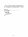
TR-79-005
A PASCAL CROSS-COMPILER FOR A MICRCCOMPDTER
by
Ganlin Jin
A thesis submitted to the faculty of
the university of North carolina at
Chapel Hill in partial fulfillment of
the requirements for the degree of
Master of Science in the Department
of Computer Science.
Chapel Hill
May 1979
Approved by:
cp~
C-i.:,
.
.
.
.
~-. . . .Advrs-e-r---------
~~-~-----Reader
GANLIN JIN.
A cross-compiler for a micrccornputer.
(Under the direction of Dr. Peter Calingaert.)
ABSTRACT
This thesis describes an implementation,
on a
microcomputer, of a cross-compiler for a subset of the
Pascal language. The microcomputer chosen here is the
MC6800 because of its availability.
Two parsing
techniques, recursive descent and LR(1), are used in
this compiler, which is written in PL/I.
ACKNOWLEDGEMENTS
The author is indebted to Dr. Peter Calingaert for
his valuable assistance in the preparation of this
thesis, to Dr. K. c. Tai of N.C. state University for
his assistance on LP. parsing, to Dr. F. P.
Brooks,
Jr.
and Dr.
s. F.
Pizer for their reading and
commenting on my thesis, to Mr. J. E. Leonarz for his
administrative help, to many fellow students in this
department who assisted me in various aspects, to my
wife. Tingrnei, for her company.
True knowledge can only be acquired
through practice.
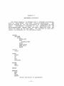
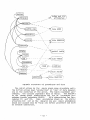
TABLE CF CCNTENTS
Chapter
page
.... .... ...
1.
INTFOD!JC'!'ION
2.
SYNTAX ANALYSIS
.
. . .
..
. .
Language SFecification • •
Parsing alqori~hrrs • • •
..
One-pass ccrrpiler • • • • •
Interrrediate code • • • • • • •
Choosing an architecture •
Chcosing the set of l-eone •
!-code optirrization • • • • • • • •
3
. . . .. .. .
3.
CODE G":NEPA'l'IC!l
. .. . . ..
.
. .. .. ..
..
.. .
..
•
..
. ..
<II
·~
7
..
..
Architecture of 8-bit rricroproc£ssors
The +:arge<: rrachine -- IICISROO • • • •
':'he architecture of IIC6ROO • • • • •
Ccns~raints irrFosed ty the MC6800
•••
Representation of data • • •
• ••
t yt:e integer •
• •
• • •
tyFe byte
•••••
":y te real
.. ..
. ..
~YFe char and ~ype Boolean
Code genera~icn for arithmetic opera~ions
Cbject proqrarr loading
••
4.
.
CONCLUSION • • •
Extensibili<:y • •
Proq::arr testing
.
...
.
..
..
7
7
"l
i 0
. .
•
11
12
12
1 1
15
15
'6
,..,
16
17
18
20
..
. .
20
20
Apper:dix
II.
s.
I NT ROD OC'YIC N
..
"'
..
.. ..
6.
..
•
Lexical rules •
Syntax rules
24
..
. .
..
-
l
-
76
Language differences ce~veen ~tandard Pascal and
Pascal-M
.. • •
• •
Festrictions .........
extensior.s • •
Data types . . . . . . . .
.
.
Ty Fe integer •
•
.. ..
TyFe byte • • • • •
Tyfe real
Type Boolean
••
TyFe char • .. • • •
• ••••
scalar and subrar.ge types • • •
~rray ~ypes
.. • • .. .. • •
.. ..
Standard procedures: inpu~ and output •
Prograrrrring exarrples
••
.
..
. .
.. .. . . . .. ..
. .
. .
7.
TH~
...
•••
I~PLE~ENTATION
8.
PROCEDURE STRUCTURE
9.
L~XICAI
40
U2
43
43
44
45
45
45
46
4A
• 49
•
..
• 49
51
ANALYSIS • •
Reserved words
• ~ ••••
Other encodinqs •
56
~
•
~
.
.
~6
')7
SY'ITAX .~NALYSIS
c;g
59
• 62
• • • • 62
• • 1'6
Encodinq cf ncnterrrinals
Syrrbol table
•••
Declaration part • •
Grarrrrar
a
..
•
•
Error recovery • •
so:aterrent par+
1 1•
~r;
15
36
so
Cpera~ors
1 o.
33
34
34
15
u1
........ 42
.
PROGRAM LOGIC MANUAL •
B
40
Dirrensicnal lirrits in Pascal-~
Constraints of target reachine • • •
Job control for running a Pascal-M program
s~ructure of a run • • • • •
Pr ograra fo rrra t • • • •
asing an object module
Inrut and output • • •
Corrpilation output format •
Source listing • • • • •
Cress reference and attribute table
Trace of compilation
Intermediate code • • • • • •
Error messages
.
Machine codes
B.
32
32
32
33
33
6"1
10
INrERMEDIATE CODE
..
Architecture
-
ii -
Speci fica~ion
i 2.
CCDE GENfPATICN
•
•
•
• • • •
• •
•
•
Me rr ox: y organization
~ irre library
BTB!.IOGRAPHY
•
•
Run
• •
iii
72
•
•
•
ga
•
8B
•
•
• 90
93
Chapter 1
INTPODUCTION
The advent of microprocessors marks the .beginning of a
The widespread
new computer revolution in this decade.
application of microprocessors,
from process control to
small accounting systems, from intelligent terminals to home
entertainment sets, indicates the revolution is well under
way.
And this revolution is far from having run its course.
Since the introduction of the first microprocessors in
the early 1970's, microprocessor systems have steadily
replaced more and more logic circuits in dedicated control
applications.
In fact,
by far the largest application of
microprocessors has been random logic replacement.
This
trend should continue with the introduction of reasonably
powerful one-chip microprocessors.
The prograrrs involved in such applications are much sn:aller than those for general purpose computers and they are
ROM, rather than RAM, based; and more than often, a single
copy of a program is replica ted thousands of times for certain applications.
In the above sense,
space efficiency
dominates all. Hand-coded machine-language programrring is a
sure way to achieve that. goal;
an assembler or a macro
assembler should suffice for this purpose.
A compiler for a
higher level language is not so urgently needed.
On the other hand, nothing in the microprocessor itself
implies that it should be used only as logic replacement.
With ever increasing complexity and speed and drastic reduction in cost, microprocessor-based systems have already
replaced dedicated minicomputers in some cases.
Together
with memory and peripheral circuitry, processor chips form
complete microcomputer systems which are threatening to
become truly general-purpose. As a matter of fact, even the
dumbest of the microcomputers of today have better performance (speed, reliability, power consumption -- not to mention price)
than the 'giant • general-purpose computers of
the early 1950's.
Microprocessors (or microcomputers) will
inevitably retrace the evolution undergone by the 'biggies•
in many aspects. For example, people will finally get tired
of assembler language programming;
will finally feel the
importance of software portability;
will finally recognize
that software costs outweigh hardware costs.
The users of
the early biggies experienced these same problems before,
-
1 -
and the solution to these p~oblems was machine-independent
higher-level prog~amming languages, so we might expect that
this should be the solution to those p~oblems faced today by
the use~s of rnicrocompute~s.
In recognizing these problems and the possible solution
to them,
people have begun to design and irrplement highe~
level languages fo~ the rnic~ocornputers.
Now, several languages have been developed for microcomputers, notably PL/M
[1q], micro-c [11], seve~al dialects of EASIC, and some subsets of Pascal.
This thesis p~oject is to implement a higher-level language on a microcomputer.
Motorola ~C6800 is chosen as the
ta~get machine
simply because we have available a mic~o
comput.er system, the SwTPC 6800, based on the MC6800 processor.
A subset of Pascal, Pascal-M (described in Appendix A) is
chosen as the highe~-level language. The advantages of Pascal over othe~ languages are that:
1. Pascal is well known;
2. Pascal is structurally strong [3];
3. Pascal is comparatively easy to irrpleroent.
Because of the lack of software suppo~t and sufficient
memory space in the microcomputer system,
it is almost
impossible to irrplernent a compile~ which ~uns on the mic~o
computer.
Therefore, the compiler for this thesis project
is a cross-compiler -- it compiles Pascal-M source programs
on the IBM 370 (under OS/360 MVT Rel. 21.8 - HASP II Ver.
3.1)
and generates code for the MC6800.
The corrpiler is
written in PL/I (OS PL/I Checkout Compiler Ver. I Bel 3.0).
The~e are logically two phases for implementing any higher-level languages.
The first phase is language dependent,
extending f~om lexical analysis th~ough syntax analysis and
semantic analysis until intermediate code gene~ation, and
probably includes some inte~mediate code optimization.
The
second phase is ta~get-machine dependent, including memory
management and object code gene~ation, and probably some
linking and loading.
The next two chapters discuss some
problems encounte~ed and desc~ibe the thinking behind some
of the design and implementation decisions in each of these
~espective phases.
- 2 -
Chapter 2
SYNTAX ANALYSIS
A corrplete
specification of a prograrrming language must
perform three functions.
First, it must specify the context-free syntax of the language; that is, which strings of
symbols are deemed to be well-formed programs.
Second, it
must specify the semantics of the language; that is, what
rreaning should be attributed to each syntactically correct
program.
Third,
it must specify the context-sensitive
requirements of the language; that is, what are scme of the
interconnections amoung different segments of a program.
The most commonly used method of syntax specification is
by .!li!S::!J!.§ !!s.l!J; !.Qk:!!l t!lll!>, which has the advantage of being
able to specify any context,-free grammar, including any
ambiguous construct.
Another important advantage of BNF is
that it can be used as input for automatic parser generators.
The disadvantage of BNF is that no semantics is
included at all. The use of BNF tends to lead to the intentional or inadvertent introduction of ambiguity where none
is present in the language being specified.
For example,
the famous ambiguity of
IF A THEN IF B THEN C ELSE 0
BNP
is caused by specifying the
as
grammar of 'if statement• in
<if stmt> ::= IF <condition> THEN <statement>
1 .IF <condition> THEN <statement> ELSE <staterrent>
<statement> ::= <if statement> 1 <other statement>
This is easily resolved by letting shift action dorrinate
reduce action whenever a such conflict occurs.
Another
e.xarrple is about parameter passing in Pascal.
.In passing
parameters to subroutines, either call by value or call by
reference could be used, depending on bow fcrmal parameters
are declared.
At the calling point, the reduction frorr
expression or variable to actual parameter is specified in
the Pascal
User Manual and Peport [ 15]
(subsequently
referred to as !h~ ]~£2!!) as
<actual parameter> ::=
<Expression>
I <variable>
-
3 -
Together with the commonly used reduction
<expression> ::= <variable>
this forms an ambiguous construct.
The ambiguity is caused
by specifying a context-sensitive construct by a contextfree grammar.
Another commonly used method of syntax specification is
by £~n~~~ g!ag~ffi, which has the advantage of being able to
let people grasp an intuitive feeling about the grammar
easily, just as with statistical diagrams, i.e., graphs (as
opposed to statistical tables).
It is very helpful in
directing people to write recursive descent parsers.
The
major disadvantage of syntax diagrams, besides their saying
nothing about semantics, is that it is not possible tc process them mechanically;
thus they cannot be used as input
for automatic parser generators.
Another important disadvantage of syntax diagrams is that it is not always possible
to represent a given programming language by means of syntax
diagrams.
For example, the syntax diagram specification of
the previous example on actual parameter in the Report is:
Actual parameter
:-.le xpression./
)>..
which has only the first half of the ENF equivalent.
Specification of the semantics and context-sensitive
requirements of a language is usually done by words, though
there are some formal definitions available [16].
The syntax specification of Pascal-M (appendix A)
is done both in
BNF and in syntax diagrams in a comFlementary way,
as is
done itt the Report.
The semantics and context-sensitive
requirements of Pascal-M are the same as specified
(in
words) in the Report.
The parsing algorithms used in this compiler were chosen
from the many standard parsing algorithms commonly available
[1,2,8,10,13].
In general, the standard parsing algorithms
can be classified into two categories: ~2~=~2~E and ~2!12~=
~E·
The terms refer to the way the syntax tree is built.
A
representative top-down parsing algorithm is ~~£~£2il~ ~~~
£!Dt [13, pp. 97-100], which has the following advantages.
It is straightforward to understand,
the Farser is easy to
write, all parsing actions are well under human control, and
no backtracking is necessary.
But it requires a language
that allows recursive calls to implement the parser.
-
4 -
Bottom-up parsing culminates in .!:.l!ll (j) (one symbol ],_ook.f!.head .l_eft-to-right scan .I.ightmost derivation)
[2] which is
the most efficient of all parsing algorithms, and the parser
can be generated automatically. Theoretically the languages
accepted by LALR (1) (or loosely LR (1)) are a subset of .!!l).S~
!l!!l.!!.2~§ context-free languages.
Actually, LR parsers can be
generated for ambiguous grammars too.
And the intentional
rewriting of an unambiguous construct into an ambiguous one
can even be exploited to reduce the number of nonterminals
and thus the number of productions [1, pp.
116-119].
The
secret lies in an important featun~ of the parser generation
algorithm;
that is, the automatic detection of ambiguities
and difficult-to-parse constructs in the language specification. The pitfalls detected can be used to guide human compiler writers to modify the output parser according to their
knowledge.
For example, in this Pascal-M thesis project,
<expression> is written for the parser generator input as
<expression> ::=
<expression> <relational operator> <expression>
<expression> <adding operator> <expression>
<expression> <multiplying operator> <expression>
<sign> <expression>
( <ex pression> )
<variable>
<unsigned constant>
D£! <expression>
instead of the Beport specification
<expression> ::= <simple expression>
1 <simple expression> <relational operator>
<simple expression>
<simple expression> ::= <term>
I <sign> <term>
1 <simple expression> <adding operator> <term>
<term> ::= <factor>
1 <term> <multiplying operator> <factor>
<factor> ::= <variable>
! ( <expression> )
1 <unsigned constant>
I .!1.2.i <factor>
Because the
efficient.
former has fewer
non terminals,
it
is more
Though LR parsers have so many advantages,
LB parsing is
not a panacea.
First, a parser generator must be available.
Second,
parsing actions are difficult for human to comprehend; should anything go wrong, it is hard to debug. Third,
the grammar of the language must be rewritten here and there
to ma~ch the nature of LP parsing.
During lR parsing there
are two parsing actions:
§Dl11 and ~Q~£g [1].
Shift
-
5 -
act. ions do nothing more than stacking a new state and
shifting to a new token.
Only during reduce actions are
semantic routines called into play.
Difficulties arise if
some semantic routines should be called at the point where
only shift action is taken.
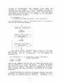
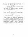
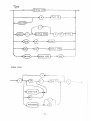
Par example, if the <if statement> is specified in RNP as
<if statement> ::=
IF <condition> THEN <statement> ELSE <statement>
the code generated from <if statement> could
ized by the following diagram.
be character-
E fo;-~.;;;,au;_~~>J
@ftsE-l
I,
I <!t;tf;~_;~-~-~ar:Y--code
'--- --- ----
>~
When the LR parser encounters THEN or ElSE, it will take
shift action;
thus the JFALSE,
JUMf and patching of their
destinat.ions will not
be generated.
If the grammar is
rewritten as
<if statement> :;=IF <condition> <then> <statement>
<else> <statement>
<then> : := THEN
<else> ::= ELSE
then we can generate code for the two jumps and patches during the reduction to <then> and <else>.
A small negligence
will cause the whole parser generation program to be rerun,
which is often costly.
Therefore, the grammar must be carefully examined and modified before processing by the parser
generator.
Beside checking the validity of program syntax, two other
functions are incoporated into the parser, building the symbol table, and driving semantic routines.
Therefore, it is
- 6 -
more convenient to divide a prograa into two parts,
a
declaration part and a statement part, which correspond to
the two functions.
In this thesis project,
recursive descent is used to
parse the declaration part and lR (1)
is used to parse the
sta ~.ement part.
(The parser generator used in this thesis
project is actually SLP(1) [9), which is almost the same as
LALP(1);
the only difference, if any,
is that the LILB(1)
might have smaller look-ahead sets.)
The advantages of LR(1)
parsing and the current trend
toward using this parsing method encouraged me to use it,
but initial lack of confidence with the LB(1) parser generator and technique made me decide to perform only part of the
syntax analysis with it.
Since recursive descent is a topdown method, any portion of the language can be parsed by a
different method, and the two methods mesh naturally.
The Pascal language is designed to be i1rplementable by
compilers.
This means that each input string in
the source program is read in only once, and the parser will
never have to go back from the beginning in order to decide
what actions to take.
One-pass corrpilation implies efficiency, but not all languages are irrplementable in one pass.
To make a language one-pass irnplementable, certain restrictions must be imposed.
In Pascal, for example, the rrost
striking and unpleasant feature is that: all .:J.Q!Q labels must
be explicitly declared.
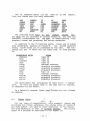
Another feature is that 35 key
words are reserved,
so that their attributes are fixed
before parsing.
A third Pascal feature, though advertised
as 'discipline of programming•, is also a consequence of
permitting one-pass compilation:
all variables must be
explicitly declared.
.QU~.::.Ei!.§§
Since Pascal-M is a subset of Pascal,
all the restrictions of Pascal caused by t:he one-pass assumption also hold
for Pascal-M.
It is natural to take advantage of this and
construct a one-pass compiler.
Many different representations
of intermediate code
exist.
The most common are:
postfix, quadruples, triples,
and indirect triples.
- 7 -
R221fiz n2!A!i2n or f2!l£1 n2!~!i2D [13, pp. 247-252] is
particularly attractive for the computer representation of
arithmetic expressions.
Explicit naming of intermediate
results is not necessary because an operand stack is used.
The major disadvantage of postfix notation is that it is not
instruction-like, being a continuous flow of a mixture of
operators and operands. Yhe representation of each entry in
this flow must be able to accommodate the largest of all
possible operators and operands.
Besides, this continuous
flow without pause is hard for humans to follow.
2.Y£!A.t:.!lll1~~ (operation code,
first operand, second operand, result) (13, pp.
252-254] representation is instruction-like, with distinct fields for operators and for operands; it remedied the disadvantage of postfix notation. But
a lot of temporary variables are introduced into quadruples,
constituting a major disadvantage.
The spell of temporary variables that haunted quadruples
is broken by the 1£.i.l21~ [13, pp. 254-256] representation,
which saves about a quarter of the space by having one less
field (the result field)
than the quadruples.
But a level
of indirection is introduced instead. 1.!ll1i!~£! !!.i.E!~§ [ 13,
pp.
256-257] offers further savings in space, but introduce
yet another level of indirection.
Another representation,
which has been chosen for this
thesis project, is a variant of the so called f=.s<.Q£1~ [4,22),
which is instruction-like and assumes a hypothetical stack
machine, similar to the Burroughs B5000 (18], as its target
machine.
Because individual entries are instructions,
P-code has the advantages of both postfix notation and quadruples.
The hypothetical stack machine of this thesis project is bas~d on the PL/0 processor [22, pp. 331-333], with
the stack modified to being only.one byte wide and with some
instructions added.
The details of the intermediate code
used are described in Appendix B.
2. 4. 2
After deciding the form of I-code (intermediate code) ,
the next thing is to choose the specific representation.
Beside ~.QD~!§!~D£~, there are three more or less conflicting
criteria in deciding what kind of operations should be
included.
1.
Convenience criterion. This seeks convenience for
the-semantic routine to use. For example, in Pascal-M there are six relational operators (>, >=,
<, <= ,=, ~=).
If we have all six corresponding
I-code Oferations (e.g. GT, GE, LT, LE, EQU, NEQ),
-
8 -
it will be most convenient for semantic routines.
Because the operands for the relaticnal operators
could be of dif.ferent data types, it might be convenient to have corresponding mixed operations,
too (e.g. for the '>' operator, we might have GTB,
GTBI, GTIB, GTI, GTR ••• etc., where B, I, R indicate byte, integer, and real operands, respectively).
The convenience criterion tends to lead
to proliferation of operations.
£S£§iiD~Bl
2.
criterion. The bigger the I-code operation set,
the more code generation routines are
needed.
The parsimony criterion tends to lead to
a smaller I-code operation set, and a minimun; sufficient set is desirable under this criterion.
The minimum se" is similar to the basis vectors
for an n-dimensional space in linear algebra, in
that any operations in this set are linearly independent of each other.
For example, the minimum
set of the above six relational operators could be
four:
GT, GE, EQU, and a COM {complement).
The
other three could be formed by combining two operations in the basis set. Besides possessing independence, the operations in the basis set should
be in some sense orthogonal,
so that all other
operations could be formed by a shorter combination of the basis se~.
Parsimony often leads to
inconvenience, and ~be I-code program tends to be
longer than had this criterion not been honored.
3.
]ffi£.i:&l!!£.Y criterion.
Onder the efficiency criterion, the object code generated from the I-code
program must be short in size and fast to execute.
Object code efficiency can be achieved by providing many specialized I-code operations; it again,
like the convenience criterion, will lead to proliferation of operations.
Besides the three foregoing criteria, the expected extent
of code optimization will influence choosing the set.
For
example, if we decide to include only four operations for
the six relational operators according to the parsimony
criterion, will that lead to longer code because '<' will be
translated into GE and COM rather than only LT?
The answer
is no, because the relational operations in Pascal-M will
appear only as tests for conditions, any relational operation will always be followed by a conditional jurrp, and a
simple optimization program later can change the pair COM
and JPF (jump if false) into JPT (jump if true) , or from COM
and JPT into JPF, so there will be no significant loss in
not providing the three o per at. ions LE, LT, and NEQ.
- 9 -
Cede optimization is usually a non-trivial task.
Since
code optimization is not ~he primary goal of this thesis
project (The primary goal is a compiler that works.), only
the following simple I-code optimization are included in
this compiler.
1.
Type byte constant folding.
2.
Load-store pair cancellation.
3.
Indirect jump elimination.
4.
COM-JPF, and coM-JPT pair transformation.
- 10 -
Chapter 3
CODE GENERATION
The target machine of the compiler which was constructed
could be any 8-bit microprocessor, simply because there are
so many similarities among them.
Though this compiler currently generates code only for the MC6800, it will be ~ore
instructive to understand first the architecture of 8-bit
microprocessors in general in order to visualize the problems associated with code generation for this particular
class of target machines.
The following is a summary of 8-bit microprocessor architecture characteristics [7].
1.
Short word size: 8 bits only.
2.
Short operation code, usually 8 bits.
3.
Variable instruction length -- which saves
space.
4.
Many address abbreviation techniques:
a)
rrernory
implicit operand.
b) immediate operand.
c) relative tranch.
d)
indexed or based addressing.
e)
register-to-register operations.
Often the
registers are implicitly specified in the operation code rather than explicitly in the operand address field.
f) many addressing modes.
5.
Few accumulators, few index registers.
6.
Stack for
dling.
subroutine linkage
-
11 -
and interrupt
han-
7.
No mutiplication, no division,
requires subsequencing.
nor anything that
All the above characteristics reflect the fact that space
efficiency dominates all in the realm of microprocessors.
3.2
3. 2. 1
The following is a summary of MC6800 architecture:
1.
Prograwmable registers:
Accumulator A ----- 8
Accumulator B ----- 8
Index register --- 16
Stack pointer ---- 16
Program counter --- 8
Status Register --- 8
bits
bits
bits
bits
bits
bits
2.
Two's corrplement number representation.
3.
Memory addressing modes:
a) Immediate addressing.
group are 2 bytes long;
operand.
Instructions of this
the second byte is the
b) Direct addressing.
Instructions of this group
are 2 bytes long; the second byte specifies the
address of an operand located in the first 2S6
bytes of memory address space.
c) Extended addressing.
Instructions of this
group consist of 3 bytes; the second and third
bytes form a 16-bit operand address.
This
addressing mode has the ability to access the
full range of the memory space (65,536 bytes).
d) Indexed addressing.
Instructions of this group
consist of 2 bytes; the second byte is an offset which will be added to the content of the
index register and the 16-bit sum will be the
operand address.
e)
4.
Inherent addressing.
Instructions of this
group have only one byte; the operand(s)
are
implicitly specified by the operation code.
Branch instructions.
There are four addressing
modes in branch instructions: relative,
indexed,
- 12 -
extended, and inherent.
In the relative mode of
branching the second byte is the offset from the
current program counter value.
The offset has a
range of [-128, t127J.
5.
status flags.
The status register stores six
flags:
carry, overflow, sign, zero, half carry,
and interrupt mask respectively.
Only half carry
is unusual.
This flag will be set whenever a
carry from bit 3 to bit 4 occurs on the last operation.
It is included in order to facilitate
decimal operations.
The leftmost two bits of the
status register are not used.
6.
TJO and memory are within a single address space.
Thus all I/O devices are addressed as memory locations.
All user programmable operations are performed on 8-bit
data in the MC6800.
Any operation that requires more than
eight hits must resort to software rrultiple-precision routines. Though the architecture of the MC6800 has provisions
for implementing multi-precision operations (e.g. the carry
condition and all operations that involve it), any such
attempt will be painfully slow.
To make matters worse, the
MC6800 has only one index register and no other indirect
addressing facilities.
This demands that all indirect
addressing be irrplemented through the lone index register.
This is a heavy blow on •block structured' languages, since
block structure requires activation record memory roanagemen+, and all accesses to variables are through the activation record indirectly.
Besides activation record management,
array indexing and arithmetic operations on the
operand stack all require indirect addressing.
The lone
index register must be loaded and stored frequently to shuttle among different uses,
which wastes a lot of time.
Another disadvantage of having only one index register is
that it is impossible to access efficiently two data structures that are more than 256 bytes apart.
The reason is
that though the index register is 2 t:ytes long, the offset
has only one byte.
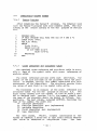
As an example of the last point, the .following is a real
problem that I encountered in a head motion parallax project.
The main idea of that project is to use photo-sensitive devices to find the position of the head of a human
observer [12].
Finding the head position in one dimension
can be reduced to an
edge finding problem.
For a
1728-element sensor, the program looks like the following:
-
13 -
FOR I:=1 TO 1728 DO
.BEGIN
(* SUBTRACT DARK LEVEL *)
A {I) :=A (I) -B (I);
(* FILTER NOISES ANt USE
*)
(* LAPLACIAN TO FIND THE EDGE *)
..
.. ...
END;
. ..
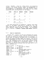
The line A(I):=A(I)-B(I) seems quite simple,
but we know
that the arrays are stored at least 1728 bytes apart.
The
offset of indexing is not able to distinguish the two data
structures if a single index value is maintained; we must
resort to loading and storing the index register twice per
iteration.
'Io simplify the illustration of this point,
we
ignore the problems of activation record management (which
needs additional indirection), and assume element types of
both A and B are type byte.
The translated code for
A (I) :=A (I) -B (I) would look like:
LDX
LDAB
INX
STX
LDX
LDAA
SBA
STAA
INX
STX
BIX
0 (X)
BIX
AIX
0 (X)
0 (X)
AIX
Index reg :=
AccB := B (I)
Index reg :-=
BIX :;: Index
Index reg :=
AccA := A{I)
1\ccA := Ace A
l\(I) := Ace A
Index reg :=
l\IX := Index
BIX
Index reg
reg
+1
AIX
-
AccB
-
(A (I)
Index reg
reg
+
B(I})
1
In constrast, if the first line of the above program were
FOR I:= 1 TO 100
and both A and B were declared as arrays of dimension 100,
then the translated code for A(I):=A(n-B(I) would be:
LDAA 0 (X)
SUDA 100 (X)
STAA 0 (X)
INX
AccA := A (I)
llccA := Ace A
B (I)
A (I) := AccA
Index reg := Index reg
-
+
1
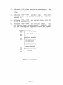
What a difference!
The Motorola company has finally realized ': hese problems,
too.
Their recent announcement [ 1 <J] on their next generation R-bit microprocessor, the MC6809, showed the following
improvements, all of which will contribute to easing the
constraints of the MC6800 and facilitate higher-level language programming.
1. another index register.
2. another user data stack, beside the linkage stack.
3. 16-bit offset indexing, beside the old 8-bit offset.
-
14 -
4. a direct page base register.
For most languages,
type integer is the basic and most
important data type.
It is used in representing integer
numbers used as arithmetic operands,
as indices fer loop
control, as subscripts for array accessing, or as codes in
encoding some information which does not necessarily have
any direct relation with integers at all. In some tiny languages or some inexpensive implementation of certain bigger
languages, only type integer is provided to the user, and
the users are forced to encode other data types by means of
integers.
on the other hand, in sorre big languages, like
PL/I or ALGOL-68, in addition to type integer and other data
types, half, quarter and various multiple-precision integers
and integer representations on different basis are provided.
In such cases, often even the name 'integer• .is subdivided
(e.g. in PL/I, FIXED BINARY, FIXED DECIMAL etc.).
What is an integer then? If we use a forrral mathematical
definition,
it would be impossible to use a fixed number of
bits to represent all possible integers. Therefore, a practical approach is used in the Report (p.
13) :
a value of
type integer is an element of the irrplementation defined
subset of whole numbers.
For bigger machines,
the choice of how to represent an
integer is simple: a •word' is a natural candidate, and the
compiler designer can sim~ly use whatever representation
for a word is specified by the machine architecture, be it
1's or 2's complement, signed magnitude, or whatever.
This
will siwplify the irrplementation of operations on integers.
For 8-bit microprocessors the word size is eight bits,
which is often not sufficient to represent the needed subset
of integers.
(Actually eight-bit word size is roore than
sufficient for a lot of control applications.)
The concepts
of word and integer must be separated, for we cannot use a
word or byte to represent all of the integers we need.
Two
bytes concatenated together could mere often satisfy our
needs, but it would make operations on integers corrt:licated.
Therefore I decided on using two representations: two bytes
for type integer,
and one byte for tY~~ DY~ (short
integer) ,
which is an extension to standard Pascal data
types.
The standard type integer will be sufficient to
represent the most commonly used whole numbers.
Type byte
possesses, however, the property of having the rrost efficient implementation.
Both types are represented in 2's
- 15 -
complement form.
Type integer has the range
+327671; type byte has the range (-128, +127].
[-32768,
3. 3. 2
As described in section 3.3.1, type byte is intended for
efficient implementation of short integers.
In order to
make full utilization of this efficiency, not only variables
but literals should be represented in one byte whenever possible.
For example, in the following declaration:
CONST A=10;
8=100;
C=1000;
constants A and B could and should be translated into type
byte, constant C into type integer.
It would be very inefficient to treat small literal numbers as type integer, as
for the '1'
in N:=Nt1.
Sometimes mixed type operation or
automatic type conversion is required.
If we have this
facility,
then the literal '1' would be translated into one
byte, independently of the type of N.
3.3.3
The choice for representing real numbers (or floatingpoint numbers) on microprocessors is not an easy task.
The
most common practice for big machines is to use distinct
representations for exponent and mantissa:
biased representation for exponent and signed magnitude representation for
mantissa.
For the microprocessors, the architecture specifications
have no floating point at all. The choice of representation
should be based on the overall efficiency of irrplementing
all arithmetic operations, including normalization and conversion. The evaluation of efficiency for these operations,
which are actually software subroutines, should be based on
the machine language level, not on the microprogramming or
hardware level (see section q.4).
After some study,
I decide~ on 3-byte precision:
one
byte for the exponent and two bytes for the mantissa.
The
harder decision, i.e., how to represent them,
was narrowed
to the following two choices.
1.
Use a uniform representation, i.e., represent both
exponent and mantissa by 2's corrplement.
-
16 -
2.
Use distinct representations,
360.
e.g.
those of IBI'J
Either choice bas some advantages over the other.
For
example, under the first choice, multiplication is straightforward to implement;
just add the two exponents and n:ultiply the two mantissae.
The second choice is selected for
this thesis project, however, for the following reasons.
1.
It offers a greater degree of
big machines.
compatibility with
2.
It allows the use of fixed-point instructions for
comparing the magnitude of floating-point numbers.
The base for the exponent is 2 in this thesis project,
instead of 16 (as in the IBM 360) , because that will cause
less precision loss during normalization; however, the range
is shortened to t 10-16, 10+161, instead of about 110-76,
10+76j.
3. 3. 4
A variable of type char is naturally represented as one
byte. A variable of type Boolean is also represented as one
byte in this project.
This is not a sacrifice of space for
time.
Per the MC6800, the address resolution is to the
byte.
Should we represent a Boolean variable by one bit,
then any manipulation on it would require more bytes of prograrnning effort, which would waste rrucb more space than it
saved.
Because microprocessors have no multiplication or division operations,
and no multiple-precision nor floatingpointing operations, all these operations rrust be programmed.
Since it requires dozens of bytes of coding for each
of these routines,
it is most convenient to store therr in a
library and call them whenever such an operation is encountered rather than generate the whole segment of code for
each occurrence. It wastes time to perform subroutine linkage for each occurrence of those seemingly simple operations, but there is no alternative under such target machine
architecture.
I considered the use of •threaded code' [4],
but it turned out to be of no use for this one .index register roachine.
-
17 -
The best we can do is to program these routines as efficiently as possible. There are a lot of algorithms for performing multiplication and division [6), but those algorithms are for coding on the microprogram level, not on the
machine-language level.
we must re-evaluate the efficiency
of each algorithm from the level of machine language.
For
example, the •one multiply' should be twice as fast as the
• sirqole shift multiply •, according to [ 6 ].
In [ 17, p.
2.15 ], which uses one multiply to do double-precision n:ultiplication (16 by 16 bits, with 32-bit result), 78 bytes o£
coding are used,
with an average time of about 1180 cycles.
I used simple shift multiply to implement the same operation, which cost me 45 bytes and an average time of about
971 cycles.
Does this contradict the theory in [6]?
No,
because logical operations at the microprogram level are
much faster than addition, whose speed is limited by carry
propagation time.
Thus those algorithms (one multiply, two
multiply, etc.)
in [ 6 J are trying their best to minimize
additions by using more logical operations.
That condition
is not true at the machine-language level -- logical operations are of the same speed as addition or subtraction.
Thus in order to reduce one addition by using several more
logical operations is not justified at the machine language
level, contrary to the examples in [17].
The rule of thumb
for a good algorithm for a machine-language routine is: the
fewer bytes of coding the tetter.
The object code generated by this cross-compiler must be
loaded into the F AM (random access rremory)
of the microcomputer. This section presents a means for doing this.
There are two
system:
ways to enter data
into our rricrccomputer
1.
Through ACTA's (asynchronous communications interface adapter) •
We have two of them: one is connected to a HP 2645 CRT terminal (the console for
the system) , the other is connected to a floppy
disk system.
2.
Through PIA •s
(parallel interface ailapter).
We
have only one PIA which is configured as output
only and is currently connected to the PDP-11/45
for the head motion parallax project.
There is no direct connection between the source machine
(IBM 370)
and the target machine
(I'!C6800).
Upon first
glance at such a system configuration, the only way to load
the object code into the microcomputer appears to be by
- 18 -
manually typing in the object code through the console
terminal.
Alternatively we are forced to change the system
configuration.
(For example, by replacing the CRT terminal
with a clumsy teletype, we could load through paper tape.)
Fortunately, the HP 2645 is an intelligent tenrinal with
a screen buffer of 2249 bytes.
~his suggests the following
solution.
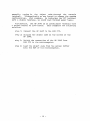
step 1: Connect the HP 2645 to the IBM 370.
step 2: Display the object code on the screen of the
HP 2645.
step 3: Switch the connection of the HP 2645 from
IBM 370 to the microcomputer.
step 4: load the object code from the screen buffer
into the RAM of the microcomputer.
-
19 -
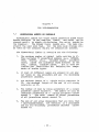
Chapter 4
CONCLUSION
This compiler is built with future extension in
therefore, the folloving decisions were made:
mind;
1.
The syntax analysis is for the whole standard Pascal.
2.
All unimplemented language features will be caught
and error messag<es printed for them, but the parser will keep on going normally.
The appearance
of an unirrplemented feature will not cause the
parser to collapse nor to generate a lot of spurious error messages.
3.
The unirrplerrented features of the declaration part
will not be entered into the symbol table.
4.
The unirrplemented features of the statement part
will have null reduction (semantic) routines.
5.
For some I-code instructions,
not irrplemen~ed.
code generation is
Future inclusion of a certain unirrplemented feature will
only have to:
1) enter some additional information into the
symbol table, or 2) fill up an empty semantic routine, or 3)
add a subroutine into the operations library for the target
machine.
The skeleton of the whole comp.iler will not be
touched at all.
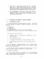
It is hard to prove the
correctness of even a moderate
program, not to mention such a compiler (which has about
6000 lines of PL/I source program). To test the compiler, I
chose some representative Pascal-M programs as test data,
compiled them on an IBM 370 and loaded and ran the object
programs on the MC6800 microcomputer.
The following three
programs were compiled and run correctly, as well as all the
example programs in Appendix A.
Therefore, at least the
-
20 -
features involved in
dependable.
those
programs
could be
considered
1.
A greatest common divisor prograrr
method, a complete simple program.
using Euclid's
2.
A factorial program, a simple exarrple of recursive
programs.
Its correct running proved the success
of activation record storage management and parameter passing mechanisms (both call by value and
call by reference).
3.
A quicksort program (QSORT) shewn following. This
is a more complex program, which includes a lot of
features:
i! statement,
!9~ statement,
!~E~!
statement, ~hi!~ statement, £2!2 statement, recursive program, local and global variables, a£!~1
variable, user defined type, and input and output
procedures.
At this writing, the following features of Pascal-M are
either not fully irrplemented or not tested completely: multi -dimensional arrays, real number operations, and character
operations.
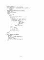
Some statistics about the compilation of the QSORT prograrr might be interesting.
The intermediate code generated
by the semantic routines has 197 instructions.
After optimization, only 134 instructions are left.
The generated
object code for the 134 instructions takes 802 bytes (not
including the run-time library).
- 21 -
PRCGRl\1'1 QSCRT;
TYPE LIST=ARP~Y[ 1 •• 30] OF BYTE;
V~R N: BYTE;
{* # OF ElEMENTS TO BE SORTED
A: LIST;
I:BYTE;
PROCEDURE QUICKSORT (L:EYTE;E:BYTE);
LABEL 100;
VAR I,J,K,T:BYTE;
BEGIN
IF L<P THEN
BEGIN
I:=L; J:=Rt1; K:=A[L ];
W!ULE TRUE DO
BEGIN
REPEAT I:=It1 UNTIL A[I ]>=K;
REPEAT J:=J-1 UNTIL A[J]<=R;
IF I<J THEN BEGHl
T:=A[I ];
.A[I ):=A( J ];
A[ J ]:=T
ENt
ELSE GOTO 100;
END;
100: T:=A( L );
A[ 1 ]:=A[ J ];
A[ J ): =T;
QUICKSORT(L,J-1);
QUICKSORT(Jt1,R)
END
END;
BEGIN
(* MAIN PROGFAM *)
READE (N) ;
FOR !:=1 TON DO READE(A(I]);
A[ Nt11:=127;
QUICKSORT { 1, N) ;
FOR I:=1 TON DO WRITEB(A[I))
END.
- 22 -
*l
Appenoix A
PASCAL-M USEE MANUAL
-
23 -
Chapter 5
INTRODUCTION
R~~£sl
is a language designed by Niklaus Wirth to be
easily and efficiently implementable on big computers, while
at the same time being a suitable vehicle for teaching programming in a systematic and well-structured fashion.
g~~
£i!1=.!:! is a dialect of Pascal designed for 8-bit microprocessors.
This manual describes a cross-compiler for
Pascal-M written in PL/I.
Chapter 2 of this manual defines
the language Pascal-M relative to standard Pascal.
Chapter
7 describes current implementation of Pascal-M.
We will use
'Pascal, user manual and report•,
2nd edition by Jensen and
Wirth [ 15] {we will simply call it the Report throughout
this manual) as the definition for standard Pascal.
This manual however, assuming the user has a reasonable
acquaintance with standard Pascal, will not atterr.pt to teach
the user how to program in Pascal.
It will only describe
the implementation-dependent features and deviations from
standard Pascal.
For users who are not familiar with Pascal, we recommend [9,15,22].
For programmers acquainted with ALGOL, PL/I, or FORTRAN,
it may prove helpful to glance at Pascal in terms of these
other languages.
For this purpose,
we list the following
characteristics of Pascal (which also hold for Pascal-M):
1.
Declaration of variables is mandatory.
2.
35 key words (e.g.
£~~jn, £DE• !hi1~, etc.)
are
reserved and cannot be used as identifiers.
In
this manual they are underscored.
(Depending on
context,
underscoring is also used to emphasize
certain key phrases in this manual.)
3.
~he semicolon
(;) is considered as a statement
separator, not as a statement terminator (as it is
in PL/I).
4.
Besides standard data types,
there is a facility
to declare new,
basic data types with symbolic
constants.
5.
Arrays may be of arbitrary dimension with arbitrary bounds; the array bounds are constant. (i.e.
there are no dynamic arrays.)
- 24 -
6.
As in FORTRAN, ALGOL, and PL;I, there is a g£!!2
statement.
Labels are unsigned integers and must
be declared.
7.
The compound statement is that of ALGOL,
responds to the DO group in PL/I.
8.
The facilities of the ALGOL switch and the computed gQ!£ of FOPTPAN are represented by the £A2~
statement.
9.
The f2! statement, corresponding to the DC loop of
FORTRAN, may only have steps of 1 (.!£!)
or -1
(gQ~Di2l and is executed only as long as the value
of the control variable lies within the lirrits.
consequently, the controlled statement may not be
executed at all.
and cor-
10. There are no conditional expressions and no rrultiple assignments.
11. Procedures may be called recursively.
12. There is no
ALGOL) •
•own• attribute for variables
(as in
13. Parameters are called either by value or by reference; there is no call by name.
14. The •block structure• differs from that of ALGOL
and PL/I insofar as there are no anonymous blocks,
i.e. each block is given a name, and thereby is
made into a procedure.
15. All objects -- constants, variables, etc.
be declared before they are referenced.
- 25 -
-- must
Chapter 6
THE LANGUAGE PASCAI-M
The lexical rules are essentially those specified in the
Report.
In deference to the EBCDIC character set, however,
a few lexical substitutions must be made:
}
(*
*l
arrow
m
(though the poir' ter is not irrplemented in
Pascal-I'!, it is included for future extension)
f
Additionally, some symbols may be entered as shown in the
Report, or they may he abbreviated.
<>
and
or
not
&
I
The underscore character is accepted as a letter,
too.
To accommodate EBCDIC as well as ASCII terminals,
Pascal-I'!
accepts : and ! in place of ( and ], respectively.
- 26 -
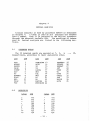
The 35 reserved words are the same as
They are listed here for easy reference.
i!!!.\!
~u.s.x
.Q~gin
£!!§~
£.2!.!.2.1:
!H.!
£.2
dcwnto
~Iii-end
j£
E!S~.Q
lill~l
H2f<rul 1!!:
nli
££..£2!£
mod
f.!!!l.£1.i.2!l
9.2!.2
Ef
in
HI~
i.lli
in the
J.l!:.2.9I.S.!X
!l£21
2!
1.!1~· l!l• Ill!,
I~~.S!
§~.!:
Report.
!.h.!W
1.9
.UJ.l~
.!!!lHl
var
i:iiJJ&
"+ h
J!l--
The reserved words
.!21!£!££, !££.9£4, .§.§!,
and .!!.!.:!:.!! are not included in current Pascal-I!, but they are
reserved nevertheless for the s'ke of compatibility with
standard Pascal and provision for· future extension.
In addition to the 35 reserved words, there are 13 words
have predefined meaning in Pascal-I!.
But unlike reserved
words, these words can be redefined by the user.
The following are the 13 words and the class each of them belongs
to •
.E.J;~S.fii!!~~ ~g;:..Q!i
S~.s!§§
Boolean
byte
integer
char
false
rea db
readi
readr
real
true
writeb
writei
writer
ty·pe ~d
type ·id
type id
type id
Boolean constant
standard frocedure
st"andard frocedure
.stan~ard procedure
type id
Boolean constant
standard Frocedure
'ilt\il.ndij.rd frocedure
standard procedure
All identifiers are recognized by their first 8 characters.
If they are longer than 8, :the rcest will be ignored,
as suggested by the Report.
In a Pascal-M program, lowe'r C!}S~ ·letters are not allowed
as symbols.
;.A_-f;t
"
For the sake of compatib lity with
standard Pascal and
provision for future extension, the syntax rules of Pascal-1'1
are made almost the same as those specified in the Report.
The syntax
The only exception is that of ££Qgr~ri D~g£j!Jg.
graph of a program as specifie4 in the Report is:
-
27 .;.;
program
~-{0 t
id
))--<;~>(~)
f-0
where the lidj
between the parentheses denotes
file identi 1er(s).
Since external files are not fully exploited in Pascal-M,
those file identifiers could be omitted.
Thus, the syntax
graph of this part is modified to:
~ogram
If any file identifier exists, it will be ignored.
Although some features of
standard Pascal are not
included in Pascal-M (e.g.
!~.!<.2!.2 type), the syntax analysis part of the compiler will process the whole language, if
it is within the dimensional limits of section 7.1.
All
attempts to use uniuplernented features will be caught in
syntax analysis and error messages will be printed, and generation of code will be suppressed; they will not cause the
compiler to collapse, however.
The actual semantically
meaningful syntax of Pascal-M is printed on the following
pages in syntax graph form for easy reference. Those graphs
are copied from the Report (pp.
116-118), with all unimplemented features deleted.
- 28 -
1
J
\2_.,
t
hl
~Q
}-:
m
\}
I
J
e
.
f __ _:_ ____ _)
0
!'
I
,_
.
'
i .i
',' .
.... J
rf
r-T--·
:c,
I'' -.l:'
.
'
.f·: ~· I.'I
:, : j ~ i
~!:i
• T
!r---'I
!
I
I
-30-
' -..
·. r
'I.
L_~:F
I
q.
.--··-
~-----,---\:
,..-......
'
\)I I~
t
\ . ~/
~1-:l
t' I
r-1
I.I L.·
, , 1 ~~
, I
:~I
1:1,-~-''· .r"J'.·)
,..J
i
(~-:)
1
II
I
~--;---~
.
~
I
L_r;,h
,7
I
'- _,
;
L._(§L.!
!
'
~!
I
:~I
1.-.r;:
~
' -2-J I
;..J~-1
-"--"'
;____(>,__:
I
'-·-
~--
I '' .I!
' ..
'
l---·
Since this compiler is a relatively srrall-scale project,
only a subset of standard Pascal language is included in
Pascal-M.
The following are the major restrictions of Pascal-M.
(Some points can be seen from the syntax graphs of
section 6. 2.)
£~£2~£,
~~!
•
.fil~·
1.
There are no
2.
There is no .f.l!!l.!<!.i.2!l facility,
dard functions.
3.
Procedure names cannot be passed as parameters.
4.
The scope of the ~!2 statement is limited to its
own defining block.
'lhus, goto•s cannot be used
for exit from procedures.
5.
standard procedures are limited to I/O only.
6.
No empty statement is allowed.
7.
The control variable of a
locally defined.
and pointer types.
and hence no stan-
f2£ statement
rrust be
6. 1. 2
For the sake of efficient execution on byte-oriented
machines, an extension to standard type
• byte•
-- is
added.
All operations legal for type integer are legal for
type byte, too.
Another extension to standard Pascal is automatic type
conversion.
Some people might think this feature violates
certain philosophical aspect of the language Pascal, but I
feel obliged to include this feature in Pascal-M
for the
following reasons.
1.
The extension
of type byte
(short integer)
requires automatic conversion between type integer
and type byte.
2.
There is no function facility in Pascal-M, and
hence no standard functions to convert between
type real and type integer (e.g.
TRUNC, BOUND,
etc) • Some other way must be provided.
- 32 -
3.
Mixed operations between type integer and
real are allowed in standard Pascal anyway.
type
A value of type integer is an element of the irrplementation-defined subset of whole numbers.
In Pascal-!!, integers are 2 bytes (16 bits) long, and in 2's complement representation internally.
The following arithmetic operators
yield an integer value when applied tc integer operands.
*
Qi!
!!).Qg
+
multiply
divide and truncate
residue
add
subtract
Integer operations are guaranteed to be correct only if
both operands and result are within (-32768, +32767].
6. 4. 2
A byte,
or short integer, is 1 tyte (8 bits)
long and
represented in 2 • s coroplement form internally.
Any number
within the range [-128, +127] could be declared as byte for
efficiency. All operations legal for type integer are legal
for type byte,
and legal for mixed operation between this
two types. The result type of roixed operations between type
integer and type byte will be of type integer with the following exception: if the dividend is of type byte and divisor is of type integer in gi! or ID.Q£ operation,
then the
result type will be byte.
6.4.3
A value of type real is an element of the implementationdefined subset of real numbers.
In Pascal-M, a rea 1 nurrber
is 3 bytes long, with 1 byte as characteristic (exponent and
sign), and 2 bytes as precision (fraction).
The quantity
expressed by a real number is the product of the fraction
and 2 (not 16 as IBM 360)
raised to the power specified by
the exponent.
The machine form of a real number resembles
that of IBM 360 floating point numbers. The leftmost bit of
the characteristic is the sign for the real number, the
remaining 7 bits are in excess-64 notation, and the 16-bit
-
33 -
Therefore the
fraction is an unsigned bi11ary null'her.
precision of real number in Pascal-M is about 5 decimal
digits, and its range is (-264,
+264),
which is about
(-10' ... +1019).
As long as at least one of the operands is of type real
(the other operand may be of type byte or type integer), the
following operators yield a real value.
*
1
+
multiply
divide (even if neither operand is real, the result
is always real)
add
subtract
caution:
After each real operation,
the result (or the
intermediate result) will probably be only partially norll'alized; repetitive operation of some kind might lead to significant less of precision.
6. 4. 4
A Boolean value is one of the logical truth values
denoted by the predefined identifiers FALSE and TRUE.
The following logical operators yield a Boolean
applied to Boolean operands.
~DQ
2!
DQ~
value when
logical conjunction
logical disjunction
logical negation
Each of the relational operators (=, <>, <=, <, >=, >)
yields a Boolean value.
Furthermore,
the type Boolean is
defined such that FALSE < TRUE.
In Pascal-M, a whole byte
is used to represent one Boolean value.
6.4.5
A value of type char is an element of a finite and ordered set of chararacters.
In Pascal-M, EBCDIC code is used
to represent each character by one byte.
Therefore, the
collating sequence of chararacters is that of EBCDIC.
- 34 -
6. 4. 6
scalar and subrange types are defined as in the Report.
In Pascal-M, a value of any scalar or subrange type will be
represented by one byte, which implies that the range of
subrange types must be no more than 256, and no more than
256 elements are allowed in a scalar type.
In section 7.1,
the number of elements in scalar types is further restricted.
6.4.7
The only data structuring facility included in Pascal-H
is ~I£~1· The elements of arrays in fascal-M are restricted
to having the elementary data types: byte,
integer,
real,
Boolean or char.
Although the number of dimensions of arrays is unlimited,
as in standard Pascal, the size of arrays is subject to the
constraint of section 3.2.
In Pascal-M,
only six input and output procedures are
included as standard procedures;
only one parameter 1s
passed to each of them.
The parameter of each of the three
input procedures is called by reference. For the three output procedures, it is called by value.
The six r;o procedures are:
RE~DH
Read in a byte; the parameter rrust of type
byte.
BEADI
Read in an integer; the parameter must of
type integer.
FEADF
Bead in a real numter; the parameter must
cf type real.
WFITEB
Print out a byte; the parameter must of type
byte, and could be an expression.
WFITEI
Print out an integer; the parameter must of
type integer, and could be an expression.
WRITEF
Print out a real number; the parameter must
of type real, and could be an expression.
-
35 -
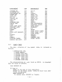
This section gives some examples of what Pascal-M programs look like.
The first example is a simple program that
will calculate the GCD (greatest common divisor) of two numbers.
This example will be used again in the next chapter
to illustrate output format.
PPOGRAII GCD;
I* THIS PROGRAM WILL FIND THE GCD OF II AND N *)
CONST 11=24; N=60;
VAR X,Y: BYTE;
BEGIN
X:=ll; Y:=N;
WHILE x~=Y DO
IF X>Y THEN X:=X-Y
ELSE Y:=Y-X;
WRITEB (X)
END.
- 36 -
The next exarrple illustrates the use of
defined data type, and sorre other features.
arrays,
a user
(* REF CONWAY & GFIES:'A PRI~ER ON PASCAL'
PAGE 268 *)
SOBT(INPDT);
CONST N=10;
TYPE LIST=ARRAY [1 •• N) OF INTEGER;
VAR L:LIST; I,M,T:INTEGER; SOPTED:EOOLEAN;
(* SORT L[ 1 •• N] USING BUBBLE SORT "')
BEGIN
SORTED :=FALSE;
PRCGBA~
M:=N;
WHILE NOT SORTED AND (M>=2) DO
BEGIN (* BUBBLE ICCP *)
{* SWAP L[ 1 •• 1'1 },PUT LARGEST IN L[M ],SET 'SORTED' *)
SCRTED:=TRUE; (* ASSUME L IS SORTED *)
FOF 1:=2 TO 1'1 DO
BEGIN (* SWAP ICCP *I
IF L[I-1] > L[I] THEN
BEGIN
T:=L[I-1];
L(I-1 ):=t[I );
L[I]:=T;
SC!lTED:=FALSE
END
END; ( SWAP LOOP *)
M:=l'l-1
END (* BUBBLE LOOP *)
END.
*
- 37 -
The following program illustrates the use of a user
defined data type (in this example,
it is scalar type)
and
the £~§§ statement,
which are unknown to most other languages.
(* THIS PROGRAM COMPUTES THE wEEKLY ~ILEAGE *l
(* OF MY CAR; I DRIVE TC UNC CAMPUS IVERY
*l
I* MONDAY, WEDNESDAY AND FRIDAY, BACH TRIP *)
(* (ROUND TRIP) TAKES ME 2 MILES.
*)
(* ON EVEFY TUESDAY AND THURSDAY, I DRIVE
*I
(* TO DUKE TO ATTIND CLASS THERE, EACH TRIP *I
(* TAKES ME 28 MILES.
*)
(* SATURDAY MORNING,! GC TO UNIVERSITY MALL *)
(* FOB SHOPPING, WHICH TAKES ME 10 MILES.
*I
(* SUNDAY NIGHT, I USUALLY VISIT I PAL,
*)
I* THAT TAKES ME 5 MORE MILES TO DRIVE.
*)
PROGRAM:MILECOUNT;
TYPE WEEKDAY=(MONDAY,TUESDAY,WEDNESDAY,
THDRSDAY,FRIDAY,SATURDAY, SUNDAY);
VIR I: WEEKDAY;
MILEAGE: BYTE;
BEGIN
MILEAGE:=O;
FOR !:=MONDAY TO SUNDAY DO
CASE I OF
MONDAY,WEDNESDAY,FRIDAY:MILEAGE:=MILEAGEt2;
TDESDAY,THDRSDAY:
MILEIGE:=MILEIGEt28;
SATURDAY:
MILEAGE:=~ILEIGEf10;
SDNCIY:
MILEAGE:=MILEAGBt5
END;(* CASE *)
WFIT!B(MILBAGE)
END.
-
38 -
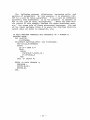
The following program illustrates recursive calls and
passing of parameters. In this example, N in procedure FACTOR is a call by value parameter:
F is a call by reference
parameter (the difference is in the presence or absence of
VARon the line of their declaration).
There are some subtle points in this example besides the above mentioned ones,
e.g.
the scope rule of block structured languages, the use
of ~he local variable LOCAL_F to avoid the function facility
(which does not exist in Pascal-H) , etc.
C* THIS PROGRAM COMPUTES THE FACTORIAL OF A NUMBER.*)
PROGRAM MAIN;
VAP. N:EYTE;
F:INTEGER;
PROCEDUFE FACTOB(N:EYTE; VIR F:INTEGER);
VAR LCCAL_F:INTEGER;
BEGIN
IF N=1 THEN F:=1
ELSE
BEGIN
FACTOR(N-1,WCAl_F);
F: =N*lOCAL_F
END
END; (* FACTOR *)
BEGIN (* MAIN PROGRAM *)
READB (N} ;
Fl\CTOF (N, F);
WRITEI {F)
END.
-
39 -
Chapter 7
THE IMPLEMENTATION
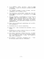
Dimensional limits are those limits caused by fixed arraY
bounds declared in the compiler itself, and which can be
changed easily by simply re-declaring the array bounds in
the compiler.
The bigger those bounds are, the less constraint the user will feel,
but the more main storage will
be taken by the compiler during the compilation process.
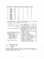
The dimensional limits i.r, Pascal-!! are the following.
1.
The maximum number of symbol table entries is 41.
This includes 13 predefined syrobols (e. g. INTEGER,
TRUE, WRITE!, etc.),
variable names, procedure
names, named and anonymous types defined by the
user, labels, constant names.
But it does not
include the identifiers for defining the components of scalar types.
2.
1\.t most 20 different names are allowed in all scalar types in one procedure and all its enclosing
procedures (blocks).
3.
The maximum length of a single string constant is
20; the rraximum length of the sum of all string
constants is 25.
4.
The .number of call by value parameters of a single
procedure cannot exceed 8.
The number of call by
reference parameters of a single procedure cannot
exceed 3.
The total number of forrral parameters
of all procedures cannot exceed 10.
5.
The sum of all array dimensions that are more than
1 (multidimensional, not vectors)
in a procedure
and all its enclosing procedures (blocks)
cannot
exceed 10.
-
!10 -
6.
An array subscript may be
maxirouro nesting 3.
an array element,
with
7.
The maximum nesting of il 21~1~~~~1, or f9I 2!~1~
ID~D!• or ~!1~ 21~!~ID~D1• or I~E&si £1s!&ID&Dl•
or
£~§~ §!~!&mgn!
is 3.
The nesting of a certain
kind of statement (e.g.
il §i~iem~Di) does not
affect the nesting of any other kind of statement
{e.g. ~hi!& 21s1£ID~ll1l·
For exarrple,
IF
WHILE
IF
WHitE
IF
WHILE
is permitted,
but
IF
IF
is not.
IF
IF
8.
9.
The maximum number of case labels in a .9.!Ul~
list
(not th€ number of case labels of a
statement, which is unlimit€d) is 4.
The maximum number
goto label is 3.
of
1QI!~Ig ~12~s
10. No more than 10 recursive
text of all procedures.
for
la.!.!£1
case
a given
calls can appear in the
The target machine could be any 8-bit wide microprocessor,
but current implementation of Pascal-M will generate code only for SwTPC 6800,
a Motorola MCS6800 based
microcomputer system designed by Southwest Technical Prods.
corp.
All operations except one in eight-bit microprocessors
are performed in eight-bit units.
The only exception is
that of memory addressing and probably some operations that
involve it.
Sith such narrow meroory width, any operation
involving a
data type more than 8 bits wide will have to
resort to software solutions.
With the limited indexing
facility,
and no other provision fer
indirect addres ing,
this makes the object code very inefficient if no restriction is imposed on the Pascal-M program.
Sowe rules are the
inevitable consequences:
-
41 -
1.
The stack of activation records will be only 256
bytes long.
This implies that no more than 256
bytes are allowed for all variables, and of course
that number must be appropriately divided by the
maximurr number of recursive calls in the program.
2.
As a consequence of the above, array size must not
exceed 256 bytes.
(The size of variables can be
calculated from elementary data type si.zes as described in section 6.4.)
g.t;.!!£i.Y.I:~
7. 3. 1
.2i. .s !l.llll
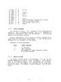
A Pascal-M program is cross-compiled at TUCC.
The minimum JCL required to compile a Pascal-M program at TUCC is as
follows:
II (JOB CARt)
//*PASSWORD
I I EXEC PASCALM
;;c.SYSIN DD (data set with your source program)
//G.HRXCODE DD (data set that will hold the machine code)
The above JCL will give you:
1.
A source list of
numbers added.
your Pascal
program with
line
2.
Error messages if any.
3.
.~
4.
Target machine code in hex, if your program has no
error.
combined attributes and cross reference table.
If you specify a dataset instead of the printer (SYSOUT=A) for the file G.HEXCODE, you will get a machine readable form of object code.
If you want a trace of shifts and reductions of the compilation process, specify after the ;;c.SYSIN card:
//C.TRACE DD SYSOUT=A
If you do not want the attributes and cross reference
table, then specify after SYSIN card, or if you have TRACE
card, specify after the TRACE card:
- 42 -
//C.XREF DD DUMMY
If you want a printout of the intermediate code generated
by compiling your program, specify after SYSTN card, and
after TRACE card and XBEF card if any, the following:
//C.ICODE DD SYSOUT=A
7.3.2
1.
The standard field for
columns 2 through 80.
2.
The standard posit.ion for carriage control for the
listing of the source program is position 1.
Only
five of the USl\ST codes are recognized for this
purpose:
blank
0
1
+
source
statements
is
space 1 line before printing
(normal printing)
space 2 lines before printing
skip to channel 1 (page eject)
space 3 lines before printing
do not space before printing
(overprinting)
carriage control characters do not appear on the
source listing.
If any character other than these
five appears in position 1, Pascal-M assumes that
the user neglected to skip position 1 and the scan
will begin in position 1.
A warning message will
be issued.
7.3.3
The code generated by the Pascal-M compiler is an object
module that can be run under the SWTBUG operating system
[ 21 ] •
To load an object program of Pascal-M,
first
the user
must load the library routines froJr, a floppy disk labelled
1 Pascal-M'
into the RAM of the SwTPC 6800:
Step 1: Hook up the HP2645 terminal to the SwTPC, turn
the duplex switch to the 'full' position.
step 2: Power on the HP terminal, the microcomputer, and
the floppy disk system
(The floppy disk system
is issued by Smoke Signal Broadcasting [20]).
-
43 -
Step 3: Put the floppy disk labelled 'DOS-68' into disk
drive unit 0; put the floppy disk labelled
'Pascal-M' into unit 1.
Step 4: Wait until SWTBUG prompts you with a dollar
sign, then enter the command: J 8020.
Step 5: Wait un~il the message: DCS-68 appears; enter
the command: GET,1:PASCAL
After th.is step the library routines will be
loaded into PAM.
Step 6: Wait until the DOS prompts you with greater than
sign, then enter command: GET,1:tCADER.
after this step, the absolute loader will be in.
Step 7: Turn the duplex switch to the 'half' position.
Sign on to TSO {don't power off the SwTPC 6800),
QED and list the dataset that contains the hex
code.
Leave the code on the HP screen.
Step 8: Logoff from TSO and switch back to the SwTPC
6800.
Step 9: Hit reset of the ndcrocom{'uter and get a dollar
sign from SWTBUG, then enter the command:
J 0000
This step transfers control to the loader.
Step 10: Turn the HP terminal to 'block mode', and enter
each line of code on the screen by hitting the
•enter• key.
Step 11: After all lines have been entered, hit the
reset again.
Step 12: After a dollar sign appears, the program should
be in PAM.
Now enter the command: J 0100
and your program will start running.
7. 3. 4
Input and output are performed interactively on the primary I/O device of the microcomputer system by calling the
s-:.anda rd procedures of section 6. 5.
The primary I/O device
of the Southwest Tech microcomputer system is the console
terminal.
In particular,
the microcomputer installed in
Phillips 273 uses an HP2645 as the console terminal.
-
44 -
1. 4
1• 4• 1
£QllgH!l'l!J.N ill!!.fUT !.Qllllll!
ll.2.1!~£~
.!illiml
After compiling the Pascal-M program, the compiler will
list the Pascal-M program with line numbers added. The following is the source listing of the GCD program of section
6. 6.
1
2
3
4
5
6
1
8
9
10
11
PROGRAM GCD;
(* THIS PROGRAM WILL PIND THE GCD OF M AND N *)
CONST M=24; N=60;
VAR X,Y: BYTE;
BEGIN
X:=M;
Y:=N;
WHILE X,:y DC
IF X>Y THEN X:=X-Y
ELSE Y:=Y-X;
WBITEB(X)
END.
The combined cross reference and attribute table is actually a dump of the symbol table with cross references of
symbols added.
The cross reference portion lists each identifier, the
number of the line and name of the procedure where the identifier is defined, and the line number associated with each
occurrence of the identifier.
The attribute portion lists
the value of each field in the symbol table entry.
The fo.llowing is an example of the cross reference and
attribute table for the GCD program of section 6.6.
The
first three columns list the number of line on which a symbol is defined (ref. section 7.4.1), the symbol itself, and
the name of the procedure where the symbol is defined, .respectively. The next column, labelled SYMTYPE, describes the
type of the symbol; the codes are:
91 constant identifier
92 function identifier (not implemented)
93 variable identifier
94 field identifier (not irr.plement ed)
95 type identi.fier
The next column,
VALUE1, roughly corresponds to the
values of symbols; a minus one in that field usually denotes
that value is undefined at compilation time.
The last
- 45 -
colurrn, OFFSIZE,
gives the offset within the activation
record.
'Ihe offset of each symbol is indispensible in
understanding the intermediate code
(see section 3.4.4).
The second line of each symbol entry lists the line number
associated with each occurrence of that symbol.
3
M
GCD
6,
91
24
3
N
GCD
6,
91
60
1
4
X
GCD
93
-1
6, 7, 8, 8, 8, 9, 10,
2
4
y
GCD
6, 7, 8, 8, 9, 9,
3
-1
'Ihe above explanation is incomplete; besides, some other
fields in the symbol table will be printed out too;
but
their major use is for the maintenance of the compiler
rather than for aiding the user to debug.
The interested
user is referred t.o f.!!§£<_gl:E:! .R!:2.SI.!!ID 1~.S.il: l1lWl!.!!l {Appendix
E) •
7. 4. 3
Because LR(1)
parsing was used for processing the statement part of a program in this compiler (recursive descent
was used for parsing the declaration part of a program),
it
is very easy to construct the parse tree for statements by
tracing the parsing actions (shift and reduce).
This can be
done by specifying the TFACE DD card as described in section
7.3.
The following is part of the trace produced during
compilation of program GCD of the previous chapter.
en the
next page, a partial tree is constructed according to the
first 11 lines of the following trace and shows that it is a
useful debugging aid.
SHIFT TO STATE
REDUCE 18
SHIFT TO STATE
SHIFT TO STATE
REDUCE 42
REDUCE 38
SHIFT TO STATE
L_ RD
16
FEDUCE
FEI:UCE
REDUCE
5
2
61
4, NEW SY!!= 93
VAR--VAR ID, VTYPE=O
B, NEW SY/1=121
2 2, NEW SYI'!= 91
UNSIGNED CONST--CONST ID
EXP--UNSIGNEI: CCNST
4 3, NEW SH!=1 09
ASSGN ST--VAR := EXP
UNLABELLED ST--ASSGN ST
ST -- UNLABElLED S'I
ST LIST--ST
- 46 -
SHIFT TO STATE
REDUCE 62
SHIFT TO STATE
REDUCE 18
SHIFT TO STATE
SHIFT TO STATE
PEDUCE 42
REDUCE 38
SHIFT TO STATE
L RD
16
REDUCE
5
REDUCE
2
REDUCE 60
SHIFT TO STATE
REDUCE 62
SHIFT TO STATE
REDUCE 83
SHIFT TO STATE
FEDUCE 18
SHIFT TO STATE
L FD
34
SHIFT TO STATE
5, NEW SHl=109
<;>--;
20, NEW SH!= 93
VAE--VAR ID, VTYPE=O
8, NEW SH!=121
22, NEW SYI'l= 91
UNSIGNED CONST--CONST ID
EXP--UNSIGNEI: CONST
43, NEW SYI'l=109
ASSGN ST--VAR := EXP
UNLABELLED S'I--ASSGN ST
UNLABELLED ST
ST
ST LIS'I--ST LIST <;> ST
5, NEW SYM=109
<;>--;
20, NEW SYI'l= 34
<WHILE>-- WHilE
15, NEW SYf'l= 93
VAR--VAR ID, VTYPE=O
30, NEW SY!1=111
<EXP>-- <VAll>
37, NEW SH!=111
--
- 47 -
I
I
I
<st list>
<st>
<unlabelled st>
I
<assignment st>
If\~,
<var>
I
I
<unsigned const>
\
<const id>
<var id>
\I
:=
X
II
;
7.4.4
Intermediate code of Pascal-M programs can he obtained by
specifying the !CODE DD card as described in section 7.3.
The following exarrple is the intermediate code of program
GCD of sect,ion 2.6.
The last column is commentary appended
to ~he intermediate code.
For the definition of the intermediate code,
the user is referred to F.i!!il.!<.i!l=ll• R£.!2£1£:2.!!)
12.!1.!£ ~.§:I.l.!!.!t! (Appendix B).
1 MARK
2 X
3 liTE
4 STE
5 LITB
6 STB
7 LODE
8 LODE
9 EQUB
10 X
1 1 ,lPF
12 LODE
13 LODE
14 GTB
15 JPF
16 LODB
17 LODB
18 SUEB
0
4
0
3
0
0
24
2
0
0
0
0
0
60
3
2
3
0
0
0
0
0
0
26
2
0
0
0
0
0
3
0
21
2
3
0
mark activation record with 4 bytes
do nothing
load literal 24
store 24 to X ~efer to the cross
reference table of sect ion 7. 4. 2)
load literal 60
store 60 to Y
load X
load Y
if X=Y ?
do nothing
jump false to 26
load X
load y
i f X>Y ?
jump false to 21
load X
load y
X-Y
-
48
-
STB
JUMP
LODB
LODB
SUBB
STB
JUMP
LODB
27 MARK
28 STB
19
20
21
22
23
24
25
26
0
0
0
0
0
0
0
2
3
2
0
3
load y
load X
Y-X
Y:=Y-X
7
0
2
3
0
0
2
0 -10
0
0
29 CALL
30 FTS
X:=X-Y
25
load X
marl< activation record with 3 bytes
store X to print l:uffer
call I'!RITEB I write out X
return
7. 4. 5
All syntactic errors, all attempts to use unirrplemented
features,
and all semantic errors that it is possible to
detect at compilation time will be reported.
No run-time
checking is provided, however.
Since a description of the error is printed instead of an
error code for each error encountered,
a list of all error
messages is not included in this manual.
Examples of error messages:
3
li
11
'['EXPECTED
'END' EXPECTED
2ND OPERAND OF 'AND' OPERATION SHOULD
BF. OF TYPE BOOLEAN.
7.4.6
The object module (6800 machine code)
will be in the
dataset speci.fied by the DD card G. HEXCODE.
Each 1 ine of
code is in absolute format,
and is composed of 40 bytes,
each byte is in 2 hex digits and therefore the 40 bytes will
occupy the whole 80 columns, except possibly for the last
line.
-
4'l -
Appendix B
PBOGRA~
-
LCGIC MANUAL
50 -
Chapter 8
PROCEDURE STRUCTURE
The whole compiler is divided into 6 external procedures,
each of which might have some internal procedures.
The
static nesting of all the procedures is diagrammed on this
page.
The dynamic structure of the procedures and the
interconnections amoung them and so1re important data and
files are shown on the next page. The function of each procedure is discussed on the following rages.
PASCAL
PROGRAM
BLOCK
ENTER_SY!I
TYPE
Sil'lPLE_TYPE
CCNST
FIELD_LIST
PARM._LIST
ERROR
GETSYM
GETCH
STMTP
TRANS
SH
RD
LRD
TRANS ERR
REDUCE
GEN
PATCH
SMNERll
GENCO DE
GEN!'l
HEX
LOAD A
LEV OFF
Static structure of procedures
- 51 -
~EF_SYMk
_.--""'....,._!,FECUF's
'
1-.--- .-;;:
~
\
I
ERFOP
1----- ~\\ - - :;;.~~~-EER-F~~
4~---·-_)
\
\
---
/
\
/
Dynamic structure of procedures and data
The solid arrows in the above graph mean procedure call,
the dotted arrows mean 'production• or •use• of data depending on the direction of the arrow.
The boxes represent procedures, the circles represent data or files.
The RECUR's
on the above graph abbreviates the set of recursive procedures inside procedure ELOCK.
BD's abbreviates for procedures FD and LPD.
Some procedures shown on the static
structure but not on the dynamic one are small procedures
which are called only by their own mother procedure and have
no outside connection.
- 52 -
The procedure PASCAL is the main program for the first
five external procedures; it initializes the symbol table
and most variables and ca~ls procedure PROGRAM to start
parsing.
After the return from PBOGBAM, the source program
should all be processed and intermediate code should be
ready to be written onto file PCODE for further processing
by procdeure GENCODE.
Should any error occur during parsing, a return code RETCD will be set to 99, which will inhibit invoking GENCODE.
The procedure PROGRAM is the top (or outer-most)
procedure of a series of recursive procedures.
A Pascal program is composed of a <program heading> and a <block>; a
<block> is divided into 2 parts,
<declaration part> and
<statement part>,
where within a <declaration part> there
might be some more <block>'s ana the cycle goes on. In this
compiler recursive descent parsing is used to parse the
<declaration part>,
procedure PROGRAM corresponds to the
nonterminal <program> in the grammar and it calls procedure
BLOCK, which corresponds to nonterminal <block>.
The procedure BLOCK maintains the symbol ta.He and calls internal
procedures TYPE, CONST, FIELD_LIST, and PARM_LIST, each of
which corresponds to a nonterminal in the grammar and all of
which help BLOCK maintain the symbol table.
Internal procedure ENTER_SYM is called whenever a symbol and its attributes are to be entered into the symbol table.
Whenever an
error is encountered during parsing the declaration part,
internal procedure ERROR is called and a set of possible
follow up tokens
(in array FSYM)
are passed to it so that
some types of error recovery are possible.
Besides trying
to recover from the error, procedure !RBCB reports the error
by writing a message onto the file ERBFILE and setting a
flag ERRPLAG,
which will later inhibit invoking object code
generation routine GENCODE.
The procedure GETSYM is the
forms the following tasks.
lexical scanner,
which per-
1.
Reads in a token and determines its meaning.
The
meaning of the token is returnEd through an exter(The encoding of tokens is
nal variable SYM.
listed in following sections.)
2.
if it is a
Returns the value of the token,
literal, through external variables VAL1, VAL2, or
STRING.
3.
Returns the name of the token, if the token is an
identifier, through external variable ID.
4.
Prints out the source program as it is
and maintains ~he cross reference table.
- 53 -
read in,
It has an internal procedure GETCH,
which is called to read
next character from the source prograrr into variable CH.
The procedure STMTP is the main routine of <statement
part>.
It is called once for each <block> of the source
program by procedure BLCCK, and then it takes over the parsing of <statement part> until its end.
The parsing algorithm used in this part is SLR(1), and a parser generator was
used to build the decision table for parsing actions.
Details will be discussed in section 10.4.
It has 5 internal procedures: TRANS, SR, F.D, LRD, and TRANSERR.
Procedure
TRANS is actually the decision table for parsing actions for
<statement part>.
It examines the top element of a state
stack STSTK and current token SYM and performs one of the
following 4 actions.
1.
Calls procedure SH, which shifts to a new state by
stacking a new state on the state stack and gets a
new token.
2.
Calls procedure RD,
which calls procedure REDUCE
to perform the necessary semantic action.
3.
Calls procedure LRD,
which is almost the same as
RD, the only difference being that procedure TRANS
looked ahead one token before it calls LRD.
4.
Calls procedure TRANSERR whenever an illegal combina ~.ion of top of S'TSTK and current token SYl! is
encountered (i.e. no table entry for this corrbination).
Procedure TFANSERR reForts at which state
a transition error is encountered and calls SH to
qo on.
The procedure REDUCE is a collection of semantic routines
of <statement part>.
It is called whenever a reduction
action is to be performed during parsing <statement part>.
The production number of which reduction is to be per formed
is passed to this procedure through variable PROD:
the procedure selects the corresporJding semantic routine and generates intermediate code accordingly.
This procedure also
pops out some tokens
from the syntax stack STSTK of procedure STMTP by decreasing the variable TOP,
which is the
pointer to the top of the syntax stack.
Two internal procedures GEN and PATCH are used by REDUCE.
Procedure GEN
generates and maintains the array of intermediate code CODE,
which is a structured array variable with 3 fields:
OPCODE,
CODELEV, and CODEOFF; procedure PATCH patches forward references whenever these destinations become known.
The procedure SHNERR is the routine to report some common
syntax errors encountered during parsing <statement part>
(e.g • confusing'[' with'('), and all semantic errors dur- 54 -
ing any part of compilation (e.g.
wrong operand type for a
certain operation).
It does not attempt to correct the
error;
it simply sets the flag ERRFlAG as procedure ERROR
does, and continues parsing.
The procedure GENCODE is a phase separate from the foregoing five external procedures .because it is source-programindependent.
It takes the intermediate code generated by
procedure PASCAL and optimizes it sorrewhat, then generates
object code from the optimized interrrediate code.
Details
of procedure G!NCODE will be discussed in chapter 12.
All the above procedures are writ ten in PL/I, and· were
compiled by OS PL/I Checkout Compiler, version 1, release
3. 0,
PTF 26.
(The PL/I optirrizing Compiler,
version 1,
release 3.0, PTF 65 has some bugs in translation of certain
SELECT statements. These bugs kept me from using the Optimizing Compiler.)
-
55 -
Chapter 9
LEXICAL ANALYSIS
Lexical analysis is done by procedure GETSYI'l as described
in chapter 1:
a token is read in and analyzed and encoded
into a number,
then it is returned tc the calling procedure
through the external variable SYI'l.
1he encodings of tokens
used in lexical analysis are listed in the following sections.
The 35 reserved words are encoded as 1,
2,
3,
respectively, according to their alphabetic order.
AND
ARRAY
BEGIN
2
3
CASE
4
FUNCTION 13
14
IF
15
IN
16
CONST
5
LABEL
DIV
6
!!CD
18
7
8
9
10
11
12
NIL
NOT
OF
19
20
21
22
23
1
DO
DOiiNTO
ELSE
END
FILE
FOR
9.2
GCTC
OR
PACKED
+
*
.•
=
(
[
>
<=
<>
1.2.15~!!
115
113
11 1
109
104
107
118
123
124
,
ii)
)
l
<
>=
,:
-
56
gtj
114
112
110
108
105
106
122
119
124
I
-
26
27
UNTIL
VAR
PI!OCEDTJR 24
~1!1
25
RECORD
TYPE
Q!!!.!!!!Q.Jlll
.t.Qk~.!l
PROGRAM
REPEAT
SET
THEN
TO
17
•••
28
29
30
31
32
33
WHILE
34
WITH
35
35,
:
:-=
120
121
126
127
..•
unsigned integer
unsigned real
string
type identifier
const identifier
function identifier
variable identifier
field identifier
procedure identifier
100
101
103
90
91
92
93
94
95
- 57 -
Chapter 10
SYNTAX ANALYSIS
Because the whole compiler is a §.Y.!li~ .§;J;:.i,:!~ll translation
process, syntax analysis, besides its apparent major funchas 2 other
tion:
§.Yll!a~ £h~£!lng (or loosely,
2~§ll13),
ireportant functions:
1. building the symbol table; and
2. driving semantic routines.
The main component of a PASCAL program is a <block>,
which is subdivided into 2 parts corresponds to the division
of labor of processing the 2 important functions of syntax
analysis:
1. <declaration part>, parsed by recursive descent; and
2. <statement part>, parsed by SIF (1).
Recursive descent is a top-down parsing method, in which
each nonterminal symbol corresponds to a procedure instead
of being merely a token.
Since the <declaration part> is
parsed by recursive descent, all the nonterminals in this
part are not encoded into numbers.
However, for a decisiontable-driven bottom-up parsing method like the farrily of LR
parsing methods, each nonterminal does not act too differently from a terminal token.
In order to enable the decision table to have uniforrr input, the nonterminals must be
encoded into simple numbers as terminal tokens are.
The
following page shows the list of nonterminals of <statement
part> and their codes.
-
58 -
.!).9.!l.t!U:mi!!2.!
1:1.!1
!l.Q!!.!:.!'il:.!!in~.!
llr!l
<SYSTEM GS>
<COMPOUND ST>
<UNLABELLED ST>
<ASSGN ST>
<GOTO ST>
<IF ST>
<REPEAT ST>
<FOR ST>
<VAR>
<INDEXED VAR>
<ARRAY VAR>
<SET>
<ACTL PARI! LIST>
<ELEMENT LIST>
<ST LIST>
<THEN>
<OF>
<CASE LIST ELEMENT>
201
203
205
207
209
211
213
215
217
219
221
223
225
227
229
231
233
23.'3
237
239
241
243
245
247
<ST P>
<ST>
<LABEL>
<PFOC ST>
<EMPTY ST>
<CASE ST>
<WHILE ST>
<WITH ST>
<EXP>
<ELIST>
<FUN DESIGNATOR>
<UNSIGNEt CONST>
<ACTL !'ARM>
<ELEMENT>
202
204
206
208
210
212
214
216
218
220
222
224
226
228
230
232
234
236
238
240
242
244
246
<~>
<CONST>
<DO>
(UNTIL>
<INITIAL VALUE>
<RECORD VAR LIST>
The data
follows.
structure of
<;>
<ELSE>
<CASE LIST E LIST>
<CASE LABEL LIST>
<CASE LABEL>
<WHILE>
<REPEA'I>
<CONTROL VAR>
<FINAL VALUE>
the symbol
table is
declared as
1 SYMTBL (1 :40) EXT,
2 SYMID CHAR (8) ,
2 SYMLEV FIXED BIN,
2 SYMTYPE FIXED BIN,
2 SUBTYPE FIXED BIN,
2 VALUE1
FIXED BIN,
2 VALUE2 FIXED BIN,
2 OFFSIZE FIXED BIN;
The interpretation of each field in SYMTBL
upon the value of SYMTYPE:
is dependent
Case SYMTYPE of
90 type id
SYMID is the name of this identifier.
SYMLEV is the static block level on which this identifier is declared.
case SUBTYPE of
0: scalar byte, OFFSIZE is 1 (byte).
- 59 -
1:
2:
3:
4:
scalar integer, OFFSIZE is 2{bytes).
scalar real, OFFSIZE is 3(bytes).
scalar boolean, OFFSIZE is 1(byte).
scalar character, OFFSIZE is 1 (byte).
5: subrange type, the range (irrpleroented as one
byte) is (VALUE1 •• VALUE2), CFFSIZE is 1 (byte).
6,7,8,9,10: arrays: byte, integer, real, boolean,
character respectively. VRLUE1 is the pointer to
dope vector (DOPE), for 1-dirrensional arrays, it
is:
(base location of vector) - (lower bound) * (element size)
VALUE2 is the number of dimensions.
91: constant id
SYMID and SYMLEV have the same interpretation as for
type id.
case SUBTYPE of
0: byte, value is in 2nd byte of VALUE1.
1: integer, value is in VALOE1.
2: real, fraction is in VALOE1, characteristic is
in the 2nd byte of VALUE2.
3: TROE(VALUE1=1) or FALSE(VALOE1=0).
4: character, value is in 2nd byte of VALUE1.
11:string, VALUE1 is the pointer to STRAREA, VALUE2
is the length of string.
92: function id (not implemented)
-
60 -
93: variable id
SYMID and SYMLEV have the same interpretation as for
type ill.
case SUBTYPE of
0: scalar byte
1: scalar integer
2: scalar real
3: scalar boolean
4: scalar character
other: index of type id .in symbol table.
If this variable is a fornal parameter called by
reference then VALU1!1=0; otherwise VliLUE1=-1.
VALUE2 is not used.
94: field id (not inplemented)
95: procedure id
SYMID is the procedm~e name.
SYMLEV is the address in P-code of this procedure; if
neqative then i t is a builtin procedure.
VALU!1 is the pointer to parameter information (PARAMNFO).
VALU!2 is the number of formal parameters of this
procedure.
OFFSIZE is the size of the activation record (in
bytes) •
96: label
SYMID is unused.
SYMLEV is the numeric value of the label.
case subtype of
0: undefined; VALUE1, VALUE2 and OFFSIZE are the
list of undefined goto•s
(therefore at most 3
forward references are allowed).
1: defined; OFFSIZE is the P-code address of label
definition.
The symbol table is ini+:ialized
defined words.
-
61 -
by the following 13 pre-
IDQf! .a.!t!.!Q
0
1
2
3
4
5
6
7
8
9
10
11
12
BYTE
INTEGER
REAL
BOOLEAN
CHAR
TRUE
FALSE
PEA DB
READ!
BEADR
WRITEB
WRITE I
WRITE!
§.Xt!!.!!!.l:< §.!!ll.:U.E£; Q..n:gg .Y!1.!JlU .YH.!J.!i.~
90
90
90
90
90
0
1
-1
1
2
2
91
91
3
3
-1
-1
-1
-1
1
95
95
95
95
95
95
-7
-8
-9
-10
3
1
1
1
1
3
4
l.j
4
4
3
-11
4
5
-12
0
1
1
1
2
3
l.j
-1
-1
-1
-1
-1
-1
-1
1
1
1
1
1
1
Besides SH!TBL,
there are some auxiliary data structures
to the symbol table, declared as follcws.
LNDEFD(13:40) FIXED BIN,/* On which lines the symbol*/
I* is defined.
*/
I.NSAPPR (13:40) CHAP (80)
/* On which lines the symbol */
VAF EXT, I* appears (only the 1st 20 *I
/*appearances are included).*/
DOPE(1:10) FIXED BIN EXT,/*Dope vector, for each array*/
/*information in it is:
*/
/* CONSTP, D2, D3, ••• Dn
*I
/* where Di is the i'th dim'n*/
DPX FIXED BIN INIT (0),
/* Index cf DOPE.
*/
STRAPEA CHAR(25) VAP EXT,/* String area.
*/
PMI FIXED BIN,
/* Index of PARMNFO.
*/
1 PII.PMNFO (1: 10) EXT,
I* Parameter information.
*/
2 POFF FIXED BIN,
/* Offset of each formal parm*/
2 PREF BIT (1) ,
/* Is i t a call by ref parm? *I
2 PTYPE FIXED BIN,
/* Type of the parameter
*/
TX FIXED BIN EXT,
/* Index of SYMTBL of last
*/
/* entered identifier.
*/
SYMX FIXED BIN EXT,
/* Index cf SYMTBL of last
*/
/* encountered identifier.
*/
Because recursive descent is used in parsing this part, it
is more convenient to express this part o.f the grammar by
syntax diagrams than by BNF.
- 62 -
'Prog 'fa. m.
;-·---,
_/ ' j
/,-
----~
_·,JPL'lCI' I·-'-',
-~
.---1
·,
--~-"'
Block
"·)
/
}---'--------------·---
I
_/
!"E--------"~-----------··---'~
'\.... ..' /
.
-0--G:LCCK 1----- ()------ ."
!-- ~OC~DnF0
1--~~,.(FUNCT0 >~
[!E)
>!PAPA~ Lisr]------>\
>[PARA!! LIST
-6~-
~-0-~L:yp~)
Type.
---r~~--~----·--~>~[s~IUM~P~L~E~TY1JP~§~---------------------
-···~.~~-----·-·-·--·-·
~-~-. . -.::J
i
\-.L...;.'oiS I
MPL E TYPE f--'-
>(i) •® -'f'm j
J
- - -.. I'IYPE
PARJ\Ii LIST
r-------(jf------ - --\
: --{''-'':9 rj{!)- I
~--,..,8
_______./
PFOCEDURE
I
I
L£<l)
- 64-
)
type.
----r-------------~1 TYPZ
Simple
ID :-------------
--~~----~1~c-n-Ns-T-AN-'T~~__j
,----_..,., C 0 " S T I D
---,--~-----~L....--+-?>1 UN~
I
!~-_ j1
IG NED I NT ~G E B 1------f----,.------~
t
i~~-------~
UNSIGNED
;,
REAL~
'---------~~CHAFA~TE!1 STFINC~---
____;
------
!'I:!lD LIST
/,.I
--·-7-
A
i
i
{)--.l ;,_, "'J_>_
~--
2, I
I
----~ <-~
-----·-- -tl - . - ---
______..;,!·,
-~
\
I
\
'
'--r"'
'"~LCONSTA.IJT j4· -~~--{I) ---f_:EI:_~_ L~ -~~~
-- ss--
)
The procedure ERROR will report syntax errors encountered
during parsing the declaration part,
and it will recover
from 3 common types of error.
If the correct sequence of symbols is
•
•
A B C ....
and the parser is expecting to process symbol 'B' while an
error is encountered, the procedure ERROR recovers from the
following 3 types of error:
1.
missing current symbol, while the next is right,
e.g.
c • .
• • A
2.
wrong symbol is encountered,
is right,
e.g.
... A D C ••
3.
an illegal symbol is inserted before
symbol,
e.g.
A D B X ••
but the next symbol
the correct
'l'he algorithm used here is simple. It is centered around
the array FSYM, follow-up symbols, which is the set of possible next symbols.
If symbol A has been read and the parser is expecting to read symbol B but reads sorrething else
as the current symbol, then the following actions will be
taken,
step 1. report error
step 2. check if the current symbol is in the follow-up
symbols. If so, then assurre a symbol is missing,
return: otherwise continue to step 3.
step 3. read in the next symbol and see if it is the
symbol which had been expected as the current
syrr·bol.
If true, then assume an illegal syrrbol
is inserted before the correct one, return; otherwise continue to step 4.
step 4. check to see if the new syrrbol is in the followup symbols.
If so, then assume the current symbol is wrong (error type 1), flag DCGSYM to scanner.
{Because next SYM is already being read in,
the next call to GETSYM will be a return only.)
- 66 -
10.11
SLR (1)
was used in parsing <statement part>.
A parser
generator (written by F. lietfer at cornell University)
was
used to produce the decision table for parsing actions. The
input to the
parser generator {the BNF
graromar for
<statement part>)
is listed on the following 2 pages.
The
output of the parser generator (the decision table) is coded
into procedure TRANS.
The actions have been briefly discussed in chapter 8; the principle of this parsing technique
can be found in [1], [2], [10].
Whenever a reduction action is called,
be it RD or LRD,
one of the semantic routines in procedure REDUCE will come
into play and some pieces of intermediate code are generated.
The set of intermediate code used in the compiler is
defined in chapter 11.
-
6'7 -
<ST P> <COMPOUND ST>
<ST> <UNLABELLED ST>
<LABEL> : <UNLABELLED ST>
<LABEL> <UNSIGNED INTEGEB>
<UNLABELLED ST> <ASSGN ST>
<FRCC ST>
<GOTO ST>
<EMPTY ST>
<COMPOUND ST>
<IF ST>
<CASE ST>
<REPEAT ST>
<WHILE ST>
<FCR ST>
<!liTH ST>
<ASSGN ST> <VAR> := <EXP>
<FUN ID> := <EXP>
<VAR> <VAR ID>
<INDEXED VAR>
<VAF> • <FIELD ID>
<VAR> w
<INDEXED VAR> <ELIST> J
<ELIST> <ELIST> , <EXP>
<ARRAY VAR> [ <EXP>
<ARRAY VIR> <VAR>
<EXP> <EXP> <RELITICNAl CP) <EXP>
<EXP> + <EXP>
<EXP> - <EXP>
<EXP> OR <EXP >
t <EXP>
- <EXP>
<EXP> <MULTIPLYING CP> <EXP>
( <EXP> )
<VAR>
<FUN DESIGNATOR>
<SET>
NOT <EXP>
<UNSIGNED CCNST>
<UNSIGNED CONST> <UNSIGNED INTEGER>
<UNSIGNED REAL>
<STRING>
<CCNST ID>
NIL
<FUN DESIGNATOR> <!UN ID>
<FUN ID> ( <ACTUAL PARAM LIST) )
<ACTUAL PARAM LIST) <ACTUAL PARAM LIST> , <ACTUAL PABAM>
<ACTUAL PARAM>
<SET> f <ELEMENT liST> )
[
]
<ELEMENT LIST> <ELEMENT>
<ELEMENT LIST> , <ELEMENT>
<ELEMENT> <EXP>
<EXP> •• <EXP>
-
68 -
<PROC ST> <PROC ID>
<PROC ID> ( <ACTUAL PAPAM liST> )
<ACTUAL PARAM> <EXP>
<PROC ID>
<GOTO ST> GOTO <UNSIGNED INTEGER>
<EMPTY ST>
<COMPOUND ST> BEGIN <ST LIST> END
<ST LIST> <ST LIST> <;> <ST>
<ST>
<;> ;
<IF ST> IF <EXP> <THEN> <ST>
IF <EXP> <THEN> <ST> <ELSE> <ST>
<TH.EN> THEN
<ELSE> ELSE
<CASE ST> CASE <EXP> <OF> <CASE LIST E LIST> END
<OF> OF
<CASE LIST E LIST> <CASE LIST E LIST> ;<CASE LIST ELEMENT>
<CASE LIST ELEMENT>
<CASE LIST ELEMENT> <CASE LABEl LIST> <:> <ST>
<EMPTY ST>
<:> :
<CASE LABEL LIST> <CASE LABEL LIST> , <CASE LABEL>
<CASE I.ABEL>
<CASE LABEL> <CCNST>
<WHILE ST> <WHILE> <BXP> <DO> <ST>
<REPEAT ST> <REPEAT> <ST LIST> <UNTIL> <EXP>
<FOR ST> FOR <CONTROL VAR> := <INITIAL VALUE> TO
(continue)
<FINAL VALUE> <DO> <ST>
<FOR ST> FOR <CONTROL VAR> := <INITIAL VALUE> DOWNTO
(continue)
<FINAl VALUE> <DO> <ST>
<CONTROL VAR> <VAR ID>
<INITIAL VALUE> <EXP>
<WHILE> WHILE
<DO> DO
<REPEAT> REPEAT
<UNTIL> UNTil
<FINAL VALUE> <EXP>
<WITH ST> WITH <RECORD VAR LIST> DO <ST>
<RECORD VAR LIST> <RECORD VAR liST> , <VAR>
<VAR>
<CONST> <UNSIGNED INTEGER>
<UNSIGNED REAL>
t <UNSIGNED INTEGER>
- <UNSIGNED INTEGER>
t <UNSIGNED REAL>
- <UNSIGNED REAL>
<CONST ID>
t <CCNST ID>
- <CONST ID>
<STRING>
- 69 -
Chapter 11
INTERMEDIATE CODE
The intermediate code is based on a hypothetical stack
machine.
Each instruction of this stack machine is corrposed
of 3 parts with the following format.
OPCODE, L, A
The OPCODE is a mnemonic which specifies not only the
operation but also the type(s) of the operand(s).
Lis the
level difference between the current procedure and the procedure where the variable is defined.
A is either a number
(e.g. in LIT's, MARK), or a program address (e.g.
in JUMP,
CALL, etc.), or an offset of data address (e.g.
in various
load and store operations).
A complete data address is composed of (L,A).
Since an operand stack is used, there is no
named register other than the prograrr counter (PC), and it
is not necessary to name explicitly the operand (s)
of any
arithmetic operation.
Therefore,
(L,A)
is not used in
arithmetic instructions {e.g.
ADD, DIV, GTR, etc.), and it
is set to (0, 0).
Following are some examples of translation
from source program statements into intermediate code.
Example 1: The first statement of GCD program in the
Pascal-M User Manual (Appendix A, p. 12)
X:=M;
where M has been declared as a constant 24, is
translated into
LITB
STB
0 24
0 2
The first instruction means load constant 24 of type
byte onto the operand stack.
The second instruction
means to store the top byte to location (0,2), which
is ~he address of X.
- 70 -
Example 2: The statement X:=X-Y of the same program is
translated into
LCDB
LODB
SUBB
0
0
0
2
3
0
STB
0
2
The first instruction means load a byte onto the
operand stack from location (0,2}, which is x. The second instruct ion loads a byte from location (0, 3) ,
which
is Y.
The third instruction is a subtract operation;
the 2 operands will be popped from tbe operand stack and
the result will be pushed onto the stack.
The last
instruction stores the top byte of the operand stack
into location (0,2).
Example 3: The following is a fragment of a Pascal-M
program.
PFOCEDUFE: A;
VAR X:EYTE;
PROCEDOBE:E;
VAB Y: BYTE;
BEGIN (* PFOCEDUBE B *)
...
X:=XtY;
...
END (*PROCEDURE B *)
BEGIN (* PRCCEDURE A *l
•••
Suppose X is translated to be at offset 2 of procedure
A, and Y is translated to be at offset 3 of procedure B,
then the statement X:=XtY will be translated into
LODE
LODB
ACDB
1
0
0
STB
1
2
3
0
2
The major difference from example 2 is that X is
translated into (1,2).
This is because X is not a local
variable, and X is declared in a Frocedure (A)
which is
one level farther out t:han the procedure (B)
where the
statement X:=XtY appears.
- 71 -
11. 2
The following
fages of this chapter attempt to specify
the intermediate code in a more precise way -- by describing
each intermediate-code instz:·uction in Pascal.
First we have
to conceive the operand stack as having 8-bit width and
unlimited depth.
Two operations PUSH and POP are associated
with accessing the operand stack:
PUSH pushes one variable
(o.f type byte)
onto the stack, while PCP pops the top element of the stack and stores it into the named variable.
In addition to POSH and PCP
we need to define some
meta-operations in order to specify fully what the intermediate code will do.
R_TO_I
B_TO_R
I_'!'O_B
F_TO__ B
F_TO_I
MOD
RBI
LBI
HBP
lBR
CHR
FORMI
FORMR
change a type byte variable into type integer.
change a type byte variable into type real.
change a type integer variable into type byte.
change a type real variable into type byte.
change a type real variable into type integer.
residue; both operands and result are integers.
extract the higher byte of an integer.
extract the lower byte of an integer.
extract the higher byte of the fraction part
of a real.
extract the lower byte of the fraction part
of a real.
extract the characteristic part of a real.
form an integer from 2 bytes.
form a real from 3 bytes.
+, -, *• ;, >, >=, <, <=, =
these operatimas are self-evident.
Some variables and constants are used in describing the
meaning of the intermediate code. They are declared as follows.
v AP LB,
HB,
LB2,
HB 2,
(* 1 ower byte of an integer or real
(* higher byte of an integ€r or real
(* temporary LB
(* temporary HB
(* characteristic part of a real
OP1B,{* 1st operand of a byte operation
OP2B (* 2nd operand of a byte operation
: BYTE;
TOP, (* top addrt1 for last activ•n record
B,
(* base address of last activ'n record
OLDB,(* temp store forB
PC,
(* prograrr counter
OP1I,(* 1st operand of an integer operation
DP2I I* 2nd operand of an integer operation
: INTEGER;
OP1R, (* 1st operand of a real operation
CH,
-
72 -
*)
*)
*)
*)
*)
*)
*l
*I
*l
*)
*l
*l
*I
"I
OP2R: (* 2nd operand of a real operation
REAL;
S:ARRAYf0 •• 255J OF BY'IE; (*main store for
(* activation record.
TEMP:ARRAY[1 •• 8] OF BYTE;(* temporary store
FUNCTION BliSE(L:BYTE) :INTEGER;
(* This function computes the base address of
(* an activation record of level L.
VAR ADDF: INTEGER; (* address of activ•n rec.
BEGIN ADDF:=B; (* set current activ•n record
(* address to ADDR.
WHILE L>O DO
BEGIN L:=L-1;
ADDR: =FORM! (S[ ADDR ] , S[ ADDRt 1 ]}
END;
BASE:=ADDF
END.
*)
*)
*l
*)
*)
*l
*)
*)
*)
PROCEDURE REFBASE(VAR J,:DY'IE, VAR A:BYTE);
I* This procedure computes the relative address*)
(* (L,A) of a call by reference variable from *l
{* the given indirect (L, A).
*)
BEGIN PUSH (S[ BASE (L) tA ]tLt1);
(* store new L *)
A:=S[ BASE (L) tAt 1 J;
(* get new A
*l
L:=PCP
(* get new L
*)
END;
- 73 -
The following are
instructions.
91 intermediate-code
(* add byte to integer *)
LB:=PCP;
HB:=POP;
OP1I:=FORMI(HB,LB);
OP2I:=B_TO_I(POP);
PUSH(HBI(CP1ItOP2I);
PUSH(LBI(OP1ItOP2I);
{*
1
(*
2 *l
'ADDB'
(* add 2 bytes *l
OP1B:=POP;
OP2B:=PCP;
PUSH (OP1BtOP2B);
(*
1 *)
'A DDI'
(* add 2 integer numbers *)
LB:=POP;
HB:=PCP;
OP1I:=FOFMI (HB,LB);
tB:=PCP;
HB:=POP;
OP2I:=FCRMI(HB,LE);
PUSH(HBI(OP1ItOP2I);
PUSH(LBI(CP1ItOP2I);
(*
4 *)
'ADDR'
{* add 2 real nurrbers *I
CH:=POP;
LB:=POP;
HB:=POP;
OP1R:=FORMR (CH, HE, tB);
*)
1
ADBI'
the meanings of the
CH~=POP;
I.B:=PCP;
I!B:=POP;
CP2R:=FORl'lR (CH, HE, tB);
PUSH (HER (OP2FtOP 1R) ;
PUSH (LBR (OP2RtOP1R);
PUSH (CHR (OP2Ft0P 1F) ;
(*
5 *)
'ADIB'
(* add an integer with a byte *)
OP 1!: =8_ TO_I (POP);
IB:=PCP;
HB:=POP;
OP2I:=FORMI(HB,L~;
PUSH(HBl(OP1ItOP2I);
PUSH(tBI(OP1ItOP2I);
I*
6 *l
'AND '
(* • and • 2 bytes *)
OP1B:=POP;
OP2B:=POP;
IF OP1B=TFUE THEN PUSH(OP2B);
ELSE PUSH (FALSE);
- 74 -
{*
7 *)
'CALL'
(* call subroutine *l
(* For a procedure call, the semantic routine *l
(* will take the following actions:
*)
(*
(*
(*
(*
(*
(*
(*
(*
(*
*)
1. Push the actual parameters onto the
operand stack.
2. Mark a new activation record and store
the dynamic link {DL) on it.
3. Pop the actual parameters from the
operand stack, and store them on the
new activation record.
4. Prepare 'the static link (SL) and tranfer control to the new procedure.
*)
*l
*)
*)
*l
*l
*)
*l
*)
{*
(*
(* The !-code 'CALL' corresponds to the last
*I
(* step of the semantic act.ions.
*)
*)
IF A>O THEN
BEGIN OLDE:=B;
B:=FORMI (S[ Bt2 ],S[Bt3 )) ;
IF L=O THIN (* copy SL *I
BEGIN HE:=S( E];
LB:=S[Bt1]
!ND
ELSE (* L=1, copy B to SL *)
BEGIN HB:=HBI(B);
LE :=LEI (E)
END;
B:=CLDB;
S(BJ:=HE;
(*high byte of SL *)
S[Bt1 ]:=LE; (* low byte of SL *l
PUSH(LBI(l'C));
PUSH (HBI (PC));
PC:=l END
EI.SE ("' T/C procedures *)
CASE A OF
-7: BEAOB;
-8: BEADI;
-9:
READR;
-10: WRTTEE;
-11: WRITE I;
-12: lllHTER
FND (* case *)
- 75 -
(*
8 *)
'CERN'
(*
char,ge next_to_top from byte to *)
(* real.
*l
LB:=POP;
HB:=PCP;
CH:=POP;
CP2R:=B_TC_R(POP);
PUSH(CHR(OP2R);
PUSH (HER (OP2R) ;
PUSH (LBR (OP2l');
PUSH(CH);
PUSH (HB) ;
PUSH (LB);
byte to real *l
9 *)
'CBRT'
(* cha11ge top from
OP1R:=B_TO_R(POP);
PUSH (HBR (OP1R) ;
PUSH (IBR (CF1R);
PUSH (CUR (OP1R);
("' 10 *)
'CIB '
(* change top from integer to byte *)
(*
lB:=POP;
BB:=POP;
PUSH (LB) ;
(*
11 *)
'CIRN'
(*
12 *)
'CIRT'
(* change next_to_top from integer
CH:=POP;
(* to real. *)
LB:=POP;
HB:=PCP;
LB2:=POP;
HB2 :=PCP;
OP2P:=I_TO_F(FOFMI(HB2,LB2));
PUSH (HBR (CP2R) ;
PUSH (LBR {OP2F) ;
PUSH (CHR (CP2R) ;
PUSH (HB) ;
POSH (LB) ;
PUSH (CH);
(*
change top from integer to real "')
LB:=PCJP;
HB:=POP;
OP1F:=I_TO_F(FOFMI(HB,LB))
PUSH (HBR(OP1R);
PUSH (LBF (OP1P);
PUSH (CHR (CP1 R);
(*
13 *l
'COM
'
*J
(* 1•s complement a byte *l
OP1B:=POP;
OP1B:=-1-CP1B;
PUSH (OP 1 E) ;
- 76 -
(*
14 *)
'CRBT'
{* change top from real to byte *)
CH:=PCP;
LB:=POP;
HB:=POP;
OP1B:=E TO B(FORM!l (CH,HB,LB));
PUSH (OP1E);
{*
1'1 *)
'CFIT'
(*
change top from real to integer *l
CH:=POP;
IB:=POP;
HB:=POP;
OP1I:=R_TO_I(FORMR(CH,HB,LB));
PUSH (HBI (OP 1I) ;
PUSH (IBI (CPU) ;
(*
16 *)
'DIVB'
{*
divide 2 bytes *)
OP1B:=POP;
OP2B:=POP;
PUSH (OP2B/GP1 B) ;
(*
17 *)
{*
18 *)
'DIVI'
(* divide 2 integers *J
LB:=POP;
HB:=PCP;
OP1T:=FOPMI(HB,LB);
LB:=POP;
HB:=POP;
OP2I:=FORMI (HB,LE);
PUSH(HBI(OP2IjOP1I);
PUSH (IBI (OP2I/OP1I);
'DIVR'
(* divide 2 reals *)
CH:=POP;
LB:=PCP;
HB:=POP;
CP1R:=FO!lMR (Cfi,HE,LE);
CH:=POP;
LB:=PCP;
HB:=POP;
GP2R :=FOlH'lH (CH, HE, LB) ;
PUSH (HBF (OP2P/OP1P);
PUSH (LBR (OP2RjOP1R);
PUSH (CUR (OP2P/OP 1R);
(*
19 *)
'DVBI'
(*
divide byte by integer *l
LB:=POP;
HB:=PCP;
OP1I:=FORMI (HB,LB);
CP2I:=B_TC_I(POP);
PUSH(I_TO_B(OP2I/OP1I));
-
77 -
(*
20 *)
'DVIB'
(* divide integer by byte *)
OP1I:=B_TO_I(POP);
LB:=PCP;
HB:=POP;
CP2I :=FORM! {HB, L E) ;
PUSH (LBI {OP 21/0P 1I) ;
PUSH(HBI(OP2I/OP1I);
(*
21 *)
'EQBI'
(* if a byte equals an integer? *)
LB:=POP;
HB:=PCP;
OP 1I:=FOFMI (RB,LE);
CP2I:=B_TC_I(POP);
IF OP1I=OP2I THEN PUSH(TFU!) ;TE
EISE POSH {FUSE) ;
("' 22 *)
'EQIB'
(* if an integer equals a byte? *)
CP1I:=B_TC_I{POP);
IB:=POP;
HB:=POP;
OP2T:=FORMI (HB, LE);
IF OP1I=CP2I THEN PUSH(TRUE);
ELSE POSH(FALSE);
(* 23 *)
'EQUB'
(* if 2 bytes are equal? *)
CP1B:=POP;
OP2B:=POP;
IF CP1B=CP2B THEN POSH(TRUE);
ELSE POSH(FALSE);
(*
24 *)
'EQUI'
(* if 2 integers are equal? *I
LB:=POP;
HB:=POP;
OP 1T:=FOPM1 (HB,LB);
LB:=POP;
LR:=POP;
CP2I:=FORMI(HB,I.E);
IF OP1l=OP21 THEN PUSH {TPUE);
ELSE PUSH(FALSE);
(*
25 *)
'EQUR'
*I
(* if 2 reals are equal? *)
CH:=PCP;
LB:=POP;
HB:=POP;
OP1P:=FOFMR(CH,HB,LB);
CH:=POP;
LB:=POP;
HB:=POP;
OP2F:=FORMR (CH,HB,IB);
IF CP1R=OP2R THEN PUSH (TRUE);
ELSE PUSH (FALSE);
- 78 -
(*
26 *)
(* 27
*)
'GEB'
(* i.f next_to_tof byte >= top byte?
OP1B:=POP;
OP2B:=POP;
IF OP2B>=OP1E THEN PUSH(TRUE);
ELSE PUSH (FALSE);
'GEBI'
(* i f next_ to_ top byte
(* integer?
>=
top
*l
*l
*)
LB:=PCP;
HB:=POP;
CP1I:=FORMI (HB,LE);
OP2I:=B TO I(POP);
IF CP2I3=CP1I THEN PUSH(TRUE);
(*
28 *)
'GEI '
(* i f next_to_top integer >= t.op *)
(* integer?
*l
LB:=POP;
HB:=PCP;
OP 1I:=FOPMI (HB,LB);
LB:=PCP;
LR:=POP;
CP2I :=FORMI (HB,LE);
IF OP2I>=OP1I THEN PUSH (TPUE);
ELSE PUSH(FALSE);
(*
29 *)
'GEIB•
(* i f next_to_top integer >= top *l
(* byte?
*l
OP1I:=B_TO_I(POP);
LB:=PCP;
HB: =POP;
CP2I :=FORMI (HB, L E) ;
IF OP2I>=OP1I THEN PUSH(TFUE};
ELSE PUSH(FALSE);
(*
30 *)
'GER
(*
31 *}
'G'IB '
'
(* i f next_to_top real >= top real?
CH:=POP;
LB:=POP;
HB:=POP;
OP1R:=FORMR(CH,HE,L8);
CH:=POP;
LB:=PCP;
HB:=POP;
CP2R :=l''ORMR (CH, H f, LB) ;
IF OP2P>=OP1F THEN PUSH (TPOE);
ELSE PUSH(FALSE);
(* i f next_to_top byte > top byte?
OP1B:=POP;
OP2B :=POP;
IF OP2B> OP1B THEN PUSH (TPUE);
ELSE POSH{FALSE);
*J
*)
(* 32 *)
'GTBI'
(* i f next _to_ top byte > top
(* integer?
*)
*l
LB:=POP;
HB:=PCP;
OP1I:=FOFMI (HB,LB);
CP2I :=B_TC_I {PCP);
IF OP2I>OP1I THEN PUSH (TRUE);
(* 33 ")
'GTI
•
if next_to_ top integer > top *)
*l
(* integer?
("'
LB:=POP;
HB:=PCP;
OP1I:=FORMI (HB,LE);
LB:=PCP;
LB:=POP;
OP2I :=FOR!H (HB, LE) ;
IF OP2I> OP1I THEN PUSH (TRUE) ;
ELSE PUSH(FALSE);
(* 34 *)
'GTIB'
(* i f next _to_tOF integer > top *J
*)
{* byte?
OP1I:=B _TO_I(POP);
LB:=PCP;
HB:=POP;
CP2I :=FOB!H (HB, LE);
IF OP2I>OP1I THEN PUSH (TPUE) ; ;
ELSE PUSH(FALSF);
(* 35 *)
'G'IR
'
•
(* 36 *)
'JPF
(* 37 *l
',J PT
(* 38 *)
'JUMP'
•
(* i f next_ to_ top real > top real? *)
CH:=POP;
LB:=PCP;
HB:=POP;
CP1R:=FORMR{CH,HE,LB);
CH:=POP;
LB:=PCP;
HB:=POP;
CP2R:=FORMR (CH, HE, lB);
IF OP 2F >OP 1R THEN PUSH (TF UE) ;
ELSE PUSH (FALSE) ;
(* jump false *)
OP1B:=POP;
IF CP1B=FALSE THEN PC:= A;
(* jump true *)
OP1B:=POP;
IF OP1B=TRUE THEN PC:= A;
(* jump
*l
PC:=A;
-
80 -
(* For loading array variables,
(* actions are:
the semantic
(*
<*
1. Evaluate the subscripts.
(* 2. Convert the subscripts into an offset
of an activation record.
(*
(* 3. Leave the offset on the operand stack
as it is being calculated.
(*
(* 4. Get the offset from the operand stack
and load the variable accordingly onto
(*
the operand stack.
(*
(*
(* The following 3 LDX's correspond to the
(* last step of the above actions.
*l
*)
*)
*)
*l
*)
*l
*l
*l
*)
*I
*l
*)
*)
(*
3'l *)
'LDXB'
(* load byte indirect *l
LB:=POP;
(*
40 *)
'LDXI'
(* load integer indirect *)
LB:=POP;
PUSH (S[ BASE (l) tlB ]) ;
(* high byte *)
PUSH (S( BASE (L) tLEt 1 )) ; (* low byte *)
( * 41 *)
'LCXF'
(* load real indirect *)
LB:=POP;
PUSH (S( BASE (L) tlE]);
(* high by+.e *)
PUSH (S[ BASE (L) tLBt 1 ]) ; (* low byte *)
PUSH(S[BASE(L)tLEt2]); (*exponent *I
(* 42
*l
'LITB'
(* load literal l:yte *)
PUSH (A);
4.~
*)
'LI TI'
(* load literal integer *)
PUSH (HBI (A)) ;
PUSH (LBI (A)) ;
(* 44 *)
'LI'!'B'
(* load literal real *)
PUSH (HBI (A) ) ;
PUSH (LBI (A)) ;
PUSH (l); (* exponent *)
I* 45 *)
'LCDB'
(* load byte *l
PUSH (S[ BASE (L) +A]) ;
(*
'LODI'
(* load integer *)
PUSH (S[ BASE (LJ+A ]) ;
(* high byte *)
PUSH (S[ BASE (LJ+A+1 ]) ; (* low byte *)
(*
46
*l
-
81
-
(*
47 *)
'LODR'
!* lead real *l
PUSH ( S[ BASE (L) +A])
PUSH (S[ BASE (L) +At 1 )) ;
PUSH (S[ BASE (L) tA+2 ]) ;
(*
48 *l
'LRFB'
{* high byte *J
I* low .byte *l
(* exponent *)
(* lead call .by reference byte *I
REFBASE(L,A);
PUSH (S[ BASE (L) tA ]) ;
(* 49 *l
'LRFI'
(* load call by reference integer *l
BEFBASE(L,A);
PUSH (S[ BASE {L) +A]);
{* high by<:.e *)
PUSH(S[BASE(L)tAt1 ]); (*low byte*)
{*
50 *)
'LRFF'
!* lead call by reference real *l
RE.FBASE (L,A);
PUSH (S[ BASE (L) tA ]) ;
{* high byte *l
PUSH (S( BASE (LJ+A+1 ]) ; (* low byte *)
PUSH (S[ BASE (L) +At2 ]) ; I* exponent *)
!* 51 *)
'LTPB'
(* load byte frorr temp area *)
PUSH (T::MP( A]) ;
(*
52 *)
' L 'I PI'
(*
53 *)
'MARK'
(* load integer frorr, temp area *)
PUSH (TEMP[ A]) ;
(* HB *l
PUSH (TEMP[At1]); (* LB *l
(* mark new activation record
*I
I* This instruction corresponds to the second *I
{* step of semantic action for procedure
*l
(* invocation. see 'CALL' for details.
*I
S[ TOPt2] :=HBI (B) ; !* D.L *l
S[ TOPt3 ]:=LBI (B) ;
(* Dl *)
B:=TCP;
TOP:=TOPtA;
(*
54"')
'MDBI'
(* mod byte by irteger *l
LB:=PCP;
HB:=POP;
OP1I:=FORMI {HB,LE);
OP2I:=B_TO_I(POP);
PUSH (I_TO_B (MOD (CP2I,OP 11)));
(*
55 *)
'MI:IB'
(* mod integer by byte *l
OP1I:=B_TO_I(POP);
lB:=POP;
HB:~POP;
CP2I :=}'ORMI (HB, LE);
PUSH(HBI(MOD(OP2I,OP1I)));
PUSH(LBI(MOD(OP2I,OP1I)));
- 82 -
(* 56 *l
I
!UBI I
{* multiply byte and integer *l
LB:=POP;
HB:=FCP;
OP1I:=FORMI (HB,LE);
CP2I:=B_TC_I(POP);
PUSH (RBI (OP 2I *OP 1I) ) ;
PUSH(LBI(OP2I*OP1I));
(* 57 *)
'MLIB'
(* multiply byte and integer *)
OP1I:=B_TO_I(POP);
LB:=PCP;
HB:=POP;
CP2I:=FORIH (HB,LE);
PUSH (HBI (OP2I*OP1I));
PUSH (LBI (CP2I*OP1I));
(* 58 *)
'MODB'
(* mod 2 bytes *I
OP1B:=POP;
OP2B:=POP;
PUSH(MCDB(CP2B,OP1E));
(* 59 *)
'MODI'
(* mod 2 integers *)
LB:=POP;
HB:=PCP;
OP1I:=FOBMI (HB,LE);
LB:=PCP;
HB:=POP;
OP2I:=FOBMI (HB, LE);
PUSH (RBI (MOD (OP2I,OP1I)));
PUSH (Ll3I (MOD (OP2I ,OP1I))) ;
60 *)
'MULB'
(*
(* multiply 2 bY":es
*l
OP1B:=POP;
CP2B:=POP;
PUSR(OP1B*OP2B);
(*
61 *)
'MULl'
(* muhiply 2 integers *I
LB:=POP;
HB:=PCP;
OP 1I:=FOEIMI (HB,LB) ;
LB:=POP;
HB:=POP;
OP2I :=FOBMI (HB, L E) ;
PUSH (RBI (OP2I*OP 1I);
PUSH (LBI (OP2I*CP 1I) ;
-
83 -
(*
62 *)
'MULR'
(* multiply 2 reals *)
CH:=POP;
LB:=PCP;
HB:=POP;
OP1R:=PORMR (CH, HE, LE);
CH:=POP;
LB:=PCP;
HB:=POP;
OP2R:=FORMR (CH, HE,LE);
PUSH (HBR (OP2F*OP 1F) ;
PUSH (LBR (OP2R*CP1R);
PUSH (CHR {OP 2R*OP 1R) ;
(*
63 *)
'NEGB'
(* negate a byte *)
OP1B:=POP;
PUSH (-CP1 E);
(*
64 *)
'NFGI'
I* negate an integer *l
LB:=POP;
HB:=PCP;
OP1I:=FORMI (HB,LE);
PUSH(HBI(-CF1I);
PUSH (LBI (-OP1I);
(*
65 *)
'NEGR'
(* negate a real *)
CH:=PCP;
LB:=POP;
HB:=PCP;
OP1R:=FORMP(CH,HB,LB);
PUSH (HBR (-CP1R);
PUSH(LBR(-OP1P);
PUSH(CHR(-CP1R);
(*
66 *)
'OR
(*
•or • 2 .tytes *l
OP1B:=POP;
OP2B :=POP;
IF OP 1B=FALSE THEN PUSH (OP2B) ;
ELSE PUSH (TRUE) ;
(* 67 *)
'POP '
(* pop a byte *)
DO WHILE ( A>O);
POP;
A:=A-1;
END;
(*
68 *)
'R'IS '
(* return from subroutine *l
TOP:=B;
HB:=S[Bt2];
LB:=S[ Bt3 ];
B:=FCRMI(HE,LB);
PC:=FORMI(POP,POP);
-
84 -
(* 69 *)
'SBBI'
(*
subtract integer frorr byte *)
LB:=POP;
HB:=PCP;
OP1I:=FOJlMI (HB,Ul);
OP2I:=B_TC_I(POP);
PUSH(HBI(OP2I-OP1I);
PUSH {LBI {CP2I-OP 1I) ;
(* 70 *)
'SBIB'
(*
'SFBI'
71
*)
(* subtract byte froro integer *l
OP1I:=B_TO_I(POP);
LB:=POP;
HB:=POP;
OP2I:=FORI!I (HB,LE);
PUSH(HBI(OP2I-OP1I);
PUSH (LBI {OP2I -OP 1I) ;
(*
store byte to call by ref integer
*i
FEFBASE (L, A) ;
LB:=PCP;
IF LB<O THEN S[BASE(L)tA]:='11111111'B;
ElSE S[BASE(L)tA]:=O;
S[ BASE (LJ+At 1 ): = IB;
(* 72
*)
'SFIB'
(*
store integer to call by ref byte *)
REF BASE (L, A) ;
S[ BASE (L) til ]:=PCf;
PCP; (* discard EB *)
(* 73 *)
1
SllFB'
(* store call by ref byte *l
!lEFBASE(L,l\);
S[ BASE (L) tA ]:=PCf;
{*74*)
'SRPI'
!* store call by ref integer *)
REFBASE(L,A);
S[BASE(L)tAt1 ]:=FOP; (* low byte*)
S(BASE(L)tA]:=POP;
(*high byte*)
(* 7S *l
'SFFR'
(* store call by ref real *)
FEFBASE (L,A);
SfBASE(L)tA+2):=PC·P; (*exponent *)
S[ BASE (L) tAt1 ]:=I'OP; (* low byte *l
S[ BASE (L) tA ]:=POP;
(* high byte *)
(* 76 *)
1
STB'
(* store byte to activation record *)
S[ BASE (L) tA ]: =POP;
("' 77 *)
1
STBI'
!* store byte to .integer *)
tB:=PCP;
IF LB<O THEN S[BASE(t)tA]:='11111111'B;
ELSE S[EASE(t)tA]:=O;
S[BASE(L)tAt1 ]i=LB;
- 85 -
(* 78 *)
'STI'
(* store integer *)
S[ BASE (L) tAt1 ]:=POP;
S[ BAS" (L)tA ]:=POP;
( * 79 *)
1
STIB'
(* low
(* high
byte *)
byte *)
(* store integer to byte *)
SfBASE(L)tA]:=POP;
POP;
(* 80 *)
'STPB'
(* store byte to temp area *)
T!!MP(A ]:=POP;
(*
81 *)
' STPI'
(* store integer to temp area *l
TE!IP[At1 ]:=POP;
TEMPfA]:=POP;
{* LB *)
HB *l
(*
(*
82 *)
'STR'
(* store real *l
5[ BASE {L) tAt2 ]:=FOP; (* exponent *l
S[ BASE {L) tAt1 ]:=FOP; (* low byte *l
Sf BASE(L) +A ]:=POF;
(* high byte *l
(*
83 *)
'SUER'
(* subtract 2 bytes *)
OP1B:=POP;
OP2B:=POP;
PUSH{OP2B-CP1B);
(* 84 *)
1
SUBT'
(* subtract 2 integers *l
LB:=POP;
HB:=POP;
OP1I:=FORMI(HR,LB);
LB:=PCP;
HB:=POP;
OP2I :=FORI'II (HB, LE);
PUSH (J!BI (OP2I-OP 11);
PUSH (LBI {OP2I-OP 1I) ;
(*
85 *)
'SUBP'
(*
subtract 2 reals *)
CH:=POP;
LB:=POP;
HB:=POP;
OP1R:=FORMll (CII, HE, LB);
CH:=POP;
LB:=POP;
HB:=POP;
OP2R :=FORMR (CII, HE, LB) ;
PUSH(HBP(OP2P-OP1B);
PUSH (LBR (0 P2R-OP 1R) ;
PUSH (CHR (OP2!l-OP 1R) ;
-
86 -
!* 86 "')
'SXB '
(*
sto~e
indirect byte *l
LB:~POP;
SfBASE(L)tPCP]:~IB;
*)
'SXBI'
(* store indirect byte to integer *l
LB:=POP;
IF LB<O THEN HB:='11111111'B;
ELSE HB:=O;
A:=PCP;
S(BASE(L)tA]:=HB;
S[BASE(L)tAt1]:=lB;
!* ss *l
•sxr •
(* store indirect intege~ *)
LB:=POP;
HB:=PCP;
A:=POP;
Sf BASE (L) tA ]:=HE;
SfBASE(L)tAt1 ]:~lB;
(*
87
SXIB'
{* sto~e indi~ect. integer to byte *)
IB:=PCP;
HB:=POP;
A:=PCP;
Sf BASE (L) tA ]: ~LB;
(*
89 *)
1
(*
'lO
'S XR '
I* store indirect real *I
CH:=PCP;
LB:=POP;
HB:=PCP;
A:=POP;
SfBASE{L)tA]:=HB;
Sf BASE (L) tAt1 ]:=18;
SfBASR(L)tAt2]:=CH;
'X
(* do nothing; this code is a result *)
(* of optimization.
"l
*)
-
87 -
Chapter 12
CCDE GENERATION
The procedure GENCODE performs the following tasks:
1. optimize the intermeoiate code by
a. eliminating load-store pairs.
b. partially unfolding some cede sequences
that involve constants.
c. eliminating indirect jumps.
2. Generate object code for the MC6800.
It is invoked only when the return code of the first
phase of compilation is zero.
It has 4 short internal procedures:
1.
GERM: appends new cooe to the array MCODE.
2.
HEX:
converts a decimal number into 2 hexadecimal
diqits.
1.
LOADl:
generates optimized
code for machine
instruction 'LCAA #Ir<:MED' (load an immediate operand into accumulator A)
by testing if IMMED is
zeta or not;
if so, then generates CLRA (clear
accumulate A) instE:ad of a load instruction.
4.
LEVOFF, generates optimized code for
LDH
LDAB
#LEV(I)
#OFF (I)
by using the same method as for LCADA.
The memory of the object machine is divided into 5 parts:
1.
Addresses 0000--0014:
temporary storage area,
reserved for temporary variables and sowe static
variables.
- 88 -
2.
Addresses 0015--0 0FF: activation record area. The
organization of an activation record is discussed
later.
3.
This area
Addresses 0100--????:
prograrr area.
extends toward the operand stack, but does not
overlap it.
4.
Addresses ????--13FF:
the operand stack, with its
bottom at address 13FF.
5.
~ddresses 1400--1BFF:
the run time library.
All
the routines like multiplication, division, and
all the routines for household chores are stored
in this area. They are listed in section 12.2.
Address
000 0
~·-------,~
temp area
gg~~
DOFF
0100
Iactiv•n
,
-- -1
records!
t----------1'
! program area
I
i
'
[
f••••••••••••ooe~
/ operand stack {
13FF
1400
r-
,
1C02
library
L_
--Ij
_i
Memory organization
- 89 -
The activation record is organized as follows; memory
locations OOOC and OOOD are for the variable B, which is the
pointer to the base address of the current activation
record; memory locations OOOE and OOOF are for the variable
TOP, which points to the top of current activation record.
In each activation record (except the first), the first byte
is the lower byte of the address of static link (since the
activation records are located at page zero, the higher byte
for the address of any activation record is 00) , the second
byte is the lower byte of the address of dynamic link, and
the rest of the bytes are for parameters passed to this procedure or local variables.
Note that the return address is
not on the activation record;
it is on the hardware linkage
stack of the machine.
1he following graph is a snap shot
for activation records of the factorial program
(see Sect.
5.6,
Pascal-M User Manual)
when N is 3 and the procedure
FAC~oF is just being invoked for the second time.
Address
oooc
OOOD
OOOE
OOOF
0015
0016
0017
0018
0019
001A
001B
001C
001D
001E
001F
0020
0021
0022
0023
0024
0025
lCCAL_F
/
Except for the most trivial ones, every intermediate code
instruction has a corresponding run tirre routine stored in
the library, which shortens the program itself considerably.
The following is the list of run time routines and their
address and function.
-
90 -
.!:2.!!.!1!!~
GB.~SE
1400
LODE
LODI
LODB
STR
STI
1411!
142C
143 F
STF
i.!!n.s:!l.2r
s\hl£~.§.2
1459
146D
1488
STEI
STIE
MARK
CALLO
1 4AA
CALL1
1 503
REF
1 510
LRFB
LFFI
LPFR
SFBI
SFIB
SFFE
SFFI
SPFF
EQUB
WFITEI
1528
1535
153F
1549
1553
155D
1567
1571
157E
GTB
GEB
DIVIB
DIVI
MODIE
MODI
DIVR
MULR
MULI
ADDBI
SUBBI
ADDIB
SUBIB
ADD!
SUBI
CPR
CPT
CIRN
CBPN
CIFT
CRRT
SUBR
15AA
15B6
1 83E
1847
1 8 52
1851'
1 84A
192F
1 961'
1990
1 99C
1 4C5
14DA
14EE
1588
1na
1984
1 9C6
19DO
1 9D1'
19E7
1A1D
1A2F
1 A44
1A5D
1A6E
get the address of ( L, A)
into index register.
routine for I-code LODE
routine for I-code LODI
routine for I-code LODF
routine for I-code STE
routine for I-code STI
routine for I-code STR
routine for I-code STEI
routine for I-code STIB
routine for T-code MARK
routine for !-code CALL i f
level difference between
caller and called is o.
routine for I-code CALL i f
level difference between
caller and called is 1.
get the base address for call
by reference variables.
routine for I-code LRFB
routine for I-code LFFI
rout.ine for I-code LBFB
routine for r-code SFBI
routine for I-code SFIB
routine for I-code SPFB
routine for I-code SFFI
routine for I-code SPFP
routine for I-code EQUB
routine for standard
procedure liPITEI
routine for I-code GTB
routine for I-code GEB
routine for I-code DVIB
routine for I-code DIVI
routine for I-code MDIB
routine for !-code MODI
routine for !-code DIVP
r·outine for: I-code MULP
routine for I-code MULl
routine for I-code ADBI
routine for I-code SBBI
routine for: I-code ADIB
routine for I-code SBI!l
routine for I-code ADDI
routine for I-code SUB!
routine for I-code CPE
routine for: r-code CRT
routine for: I-code CIPN
routine for r-code CBRN
routine for I-code CIRT
routine for I-code CBFT
routine for I-code SUBR
-
91
-
ADDR
DIVB
1l\ 74
1AED
MODB
DIVBI
MODBI
MULB
MULBI
MULI!l
WFITEB
1AFC
1E62
1 E75
1B84
1 BC4
PEADB
1BD6
1AFO
1AF9
routine for I-code ADDR
routine for I-code DIVB
routine for I-code MODB
routine for I-code DVBI
routine for !-code MDBI
routine for I-code MIJIB
routine for I-code MLBI
routine for I-code I! LIB
r:outine for standard
procedure liRITEB
routine for standard
procedure FE ADB
-
92 -
BIBLIOGRAPHY
[1
J
Aho, A. v., and Johnson, s.c., LR farsing
Computing surveys, Vol.6, No.2, June 1974, pp. 99-124.
[21 Aho, A.V., and Ullman, J.D.,
!l~£1.9!!
EI:i!:!S.i.El.!l.§ .£f
£.2!!.E.i!~!
Reading, MA: Addison-Wesley, 1977.
[3] Alpert, s.R., Pascal: A Structurally strong Language
Peterborough, NH: Byte Publications Inc., Byte
Magazine, Vol.3, No.8, August 1978, pp. 78-88.
[4] Ammann, u., et al., 11!~ R~.§.fs! (.f) !;.QID.EJ.!.§f : !.!!.El~ID!illl=
tation Notes
revTsed-edThon. zurich: Eidgenossische Technische
Hochschule, July 1976.
[51 Bell, J.R., Threaded Code
Communications of the ACM, Vol.16
pp. 370-372.
No.6, June 1973,
G. A.
].!.9.!1~1 ~.Y.§!;.§.!] 1.&r.E1~ID~!lls.ti.2I!
Englewood Cliffs, NJ: Prentice-Hall, 1976.
[ 61 BlaatiW •
[71 Brooks, F.P., Jr., An Overview of Microcomputer Architecture and Software
Second Symposium on Micro Architecture, EUROMICRO,
1976.
(81 Calingaert, P.,
lBD!.ilsi.i.Q!l
Potomac, MD:
!2.§.§!.!:]1~!:.§·
Cornpu~er
£QID.Eil.§f§, sllQ R!QS!siD
science Press, Inc. 1978.
(Q) Conway, P., Gries, D., and Zirnroerrran, E.C.
! R.I:.!!!J£lf 9!l R!ll£!1
Cambridge, MA: Winthrop, 1976.
(10] DeFamer, F.L., Simple LR(K) Grarnrrars
Communications of the ACM, Vol.14, No.7, July 1971,
pp. 45 3-460.
[ 11 ] Dreizen, H.M., ~icro-c User's Manual
Chicago: Dept. of-Infor~atia; Engln~ering, University
of Illinois at Chicago Circle, 1976.
-
93 -
[12] Fuchs, H., et al., A System for Automatic Acquisition
of Three Dimensional Data
Proc. of National Computer Conference, 1977, pp. 49-53
[ 1 3 ] Gries , D. , f,'l!!!.Eil!l:&: £9!!iii.!I.Y.£.!i.Q.!l f.Q.!: Qig.!:a! .!;S!!!ll?.Bl!li.§
New York: John Wiley & Sons, 1971.
[14] Intel corp, .§QQ.§ .sn£1 .§Ql!.Q i1Lll .EI.2$li.S!!!!!!insr !!!.s.!l.Y!.!
Santa Clara, CA: Intel corp, 1975.
[ 151 Jensen, K., and Wirth, N., R.!!e£.2.! .:.: !1.2~! .!!.S!l!!it!
.B~l!.Q.£1:
.snJ!
2nd edition, New York, Berlin: Springer-Verlag, 1975.
(16] Marcotty, M., Ledgard, H.F., Bachmann, G.v., 1 sampler
of Formal Definitions
Computing surveys, Vol. 8, No. 2, June 1976,
pp. 191-276.
[17] ~i~IQ.E!Q£~.2.22! ].E.Eli~.!l.Q.!l .!!~.!l.Y.!!.!
Motorola Semiconductor Products Inc.
New York: McGraw-Hill,1975.
( 18] organick, E.T., f.Q!!!.E.YS~r ~~.§.!~!!! ,!;!!l.S.!li~.s!l.Q.!J: !h~
ll~1QQL21.Q.Q a~Ii.!l§
New York: Academic Press, Inc., 1973.
[19) Ritter, T., and Boney, J., A Microprocessor For the
Revolution: the 6809
Peterborough, NH: Byte Publications Inc., Byte
Magazine, Vol.4, No.1, Jan. 1979, pp. 14-42.
[20J ~!!!2!~ ~i!lD.s1 lli.QAJ!£.se!iD!l• llfl!.:§§ ~.§!~!!! ~.sn.Ygj
Hollywood, CA: Smoke signal Broadcasting, 1977.
[21) ~~!]!JQ, §§Q.Q !Q.!! .!!2.!li!2I• ~~I.§iS!D J . .Q, Q.§§!.§ Q.Yi£~
San Antonio, TX: southwest Technical Prods. corp,
1977.
=
[22) Wirth, N., ~1!:!.2!i.!h!!!.2 ± ].219 ~.!!]£1.J.!I~.§
R!.Qgrg~§
Englewood cliffs, NJ: Prentice-Hall, 1976.
- 94 -