1
FX3U-ENET-ADP
USER'S MANUAL
Safety Precautions
(Read these precautions before use.)
Before installation, operation, maintenance or inspection of this product, thoroughly read through and
understand this manual and the associated manuals. Also, take care to handle the module properly and
safely.
This manual classifies the safety precautions into two categories:
and
.
Indicates that incorrect handling may cause hazardous conditions, resulting in death or severe
injury.
Indicates that incorrect handling may cause hazardous conditions, resulting in medium or slight
personal injury or physical damage.
Depending on the circumstances, procedures indicated by
may also cause severe injury. In
any case, it is important to follow all usage directions. Store this manual in a safe place so that it can be taken
out and read whenever necessary. Always forward it to the end user.
1. DESIGN PRECAUTIONS
Reference
•
Make sure to include the following safety circuits outside the PLC to ensure safe system operation even during
external power supply problems or PLC failure.
Otherwise, malfunctions may cause serious accidents.
1) Above all, the following components should be included: an emergency stop circuit, a protection circuit, an
interlock circuit for opposite movements (such as normal vs. reverse rotation), and an interlock circuit (to prevent
damage to the equipment at the upper and lower positioning limits).
2) Note that when the PLC main unit detects an error during self diagnosis, such as a watchdog timer error, all
outputs are turned off. Also, when an error that cannot be detected by the PLC main unit occurs in an input/
output control block, output control may be disabled.
External circuits and mechanisms should be designed to ensure safe machinery operation in such cases.
18
Reference
•
Observe the following items. Failure to do so may cause incorrect data-writing through noise to the PLC and result
in PLC failure, machine damage or other accident.
1) Do not bundle the control line together with or lay it close to the main circuit or power line. As a guideline, lay the
control line at least 100mm (3.94") or more away from the main circuit or power line.
Noise may cause malfunctions.
2) Ground the shield wire or shield of a shielded cable. Do not use common grounding with heavy electrical
systems.
18
2. INSTALLATION PRECAUTIONS
Reference
•
Make sure to cut off all phases of the power supply externally before attempting installation work.
Failure to do so may cause electric shock.
(1)
27
Safety Precautions
(Read these precautions before use.)
Reference
•
•
•
•
•
•
Use the product within the generic environment specifications described in PLC main unit manual (Hardware
Edition).
Never use the product in areas with excessive dust, oily smoke, conductive dusts, corrosive gas (salt air, Cl2, H2S,
SO2, or NO2), flammable gas, vibration or impacts, or expose it to high temperature, condensation, or rain and
wind.
If the product is used in such conditions, electric shock, fire, malfunctions, deterioration or damage may occur.
Do not touch the conductive parts of the product directly.
Doing so may cause device failures or malfunctions.
Install the product securely using a DIN rail or mounting screws.
Install the product on a flat surface.
If the mounting surface is rough, undue force will be applied to the PC board, thereby causing nonconformities.
When drilling screw holes or wiring, make sure that cutting and wiring debris do not enter the ventilation slits.
Failure to do so may cause fire, equipment failures or malfunctions.
Connect the FX3U-ENET-ADP securely to special adapter connector.
Loose connections may cause malfunctions.
27
3. WIRING PRECAUTIONS
Reference
•
Make sure to cut off all phases of the power supply externally before attempting wiring work.
Failure to do so may cause electric shock or damage to the product.
31
Reference
•
•
•
•
Perform class D grounding (grounding resistance: 100
or less) to the grounding terminal on the FX3U-ENET-ADP
with a wire of cross-sectional area 0.5 to 1.5 mm2. Do not use common grounding with heavy electrical systems
(refer to the Section 5.1).
When drilling screw holes or wiring, make sure that cutting and wiring debris do not enter the ventilation slits.
Failure to do so may cause fire, equipment failures or malfunctions.
Make sure to properly wire to the terminal block (European type) in accordance with the following precautions.
Failure to do so may cause electric shock, equipment failures, a short-circuit, wire breakage, malfunctions, or
damage to the product.
- The disposal size of the cable end should follow the dimensions described in the manual.
- Tightening torque should follow the specifications in the manual.
- Twist the end of strand wire and make sure that there are no loose wires.
- Do not solder-plate the electric wire ends.
- Do not connect more than the specified number of wires or electric wires of unspecified size.
- Affix the electric wires so that neither the terminal block nor the connected parts are directly stressed.
Make sure to observe the following precautions in order to prevent any damage to the machinery or accidents due
to abnormal data written to the PLC under the influence of noise:
1) Do not bundle the main circuit line together with or lay it close to the main circuit, high-voltage line or load line.
Otherwise, noise disturbance and/or surge induction are likely to take place. As a guideline, lay the control line
at least 100mm (3.94") or more away from the main circuit or high-voltage lines.
2) Ground the shield wire or shield of the shielded cable at one point on the PLC. However, do not use common
grounding with heavy electrical systems.
31
4. STARTUP AND MAINTENANCE PRECAUTIONS
Reference
•
•
•
Do not touch any terminals or connector while the PLC's power is on.
Doing so may cause electrical shock or malfunctions.
Before cleaning or retightening screws, externally cut off all phases of the power supply.
Failure to do so may cause malfunction or failure of this adapter. When the screws are tightened insufficiently, they
may fall out and cause a shortcircuit or malfunction. When tightened too much, the screws or the adapter may be
damaged, resulting in short-circuit, or malfunction.
When controlling the PLC (especially when changing data, the program or changing the operating conditions)
during operation, ensure that it is safe to do so.
(2)
18
Safety Precautions
(Read these precautions before use.)
Reference
•
•
•
Do not disassemble or modify the adapter.
Doing so may cause fire, equipment failures, or malfunctions.
For repair, contact your local Mitsubishi Electric representative.
The adapter case is made of resin. If dropped or subjected to strong impact, the adapter may be damaged.
When this adapter is installed or removed from the panel, make sure to externally cut off all phases of the power
supply. Failure to do so may cause malfunction or failure of this adapter.
18
5. DISPOSAL PRECAUTIONS
Reference
•
Please contact a certified electronic waste disposal company for the environmentally safe recycling and disposal of
your device.
18
6. TRANSPORTATION AND STORAGE PRECAUTIONS
Reference
•
The product is a precision instrument. During transportation, avoid any impacts. Failure to do so may cause failures
in the product.
After transportation, verify the operations of the product.
(3)
18
Safety Precautions
(Read these precautions before use.)
MEMO
(4)
FX3U-ENET-ADP User's Manual
FX3U-ENET-ADP
User's Manual
Manual number
JY997D45801
Manual revision
D
Date
5/2013
Foreword
This manual describes the FX3U-ENET-ADP Ethernet communication special adapter and should be read
and understood before attempting to install or operate the hardware.
Store this manual in a safe place so that you can take it out and read it whenever necessary. Always forward
it to the end user.
This manual confers no industrial property rights or any rights of any other kind, nor does it confer any patent licenses. Mitsubishi
Electric Corporation cannot be held responsible for any problems involving industrial property rights which may occur as a result of
using the contents noted in this manual.
© 2012 MITSUBISHI ELECTRIC CORPORATION
1
FX3U-ENET-ADP User's Manual
Outline Precautions
• This manual provides information for the use of the FX3U-ENET-ADP Ethernet communication special
adapter. The manual has been written to be used by trained and competent personnel. The definition of
such a person or persons is as follows;
1) Any engineer who is responsible for the planning, design and construction of automatic equipment using
the product associated with this manual should be of a competent nature, trained and qualified to the
local and national standards required to fulfill that role. These engineers should be fully aware of all
aspects of safety with aspects regarding to automated equipment.
2) Any commissioning or maintenance engineer must be of a competent nature, trained and qualified to the
local and national standards required to fulfill the job. These engineers should also be trained in the use
and maintenance of the completed product. This includes being familiar with all associated manuals and
documentation for the product. All maintenance should be carried out in accordance with established
safety practices.
3) All operators of the completed equipment should be trained to use that product in a safe and coordinated
manner in compliance with established safety practices. The operators should also be familiar with
documentation that is connected with the actual operation of the completed equipment.
Note: the term 'completed equipment' refers to a third party constructed device that contains or uses the
product associated with this manual.
• This product has been manufactured as a general-purpose part for general industries, and has not been
designed or manufactured to be incorporated in a device or system used in purposes related to human life.
• Before using the product for special purposes such as nuclear power, electric power, aerospace, medicine
or passenger movement vehicles, consult with Mitsubishi Electric.
• This product has been manufactured under strict quality control. However when installing the product
where major accidents or losses could occur if the product fails, install appropriate backup or failsafe
functions into the system.
• When combining this product with other products, please confirm the standards and codes of regulation to
which the user should follow. Moreover, please confirm the compatibility of this product with the system,
machines, and apparatuses to be used.
• If there is doubt at any stage during installation of the product, always consult a professional electrical
engineer who is qualified and trained in the local and national standards. If there is doubt about the
operation or use, please consult your local Mitsubishi Electric representative.
• Since the examples within this manual, technical bulletin, catalog, etc. are used as reference; please use it
after confirming the function and safety of the equipment and system. Mitsubishi Electric will not accept
responsibility for actual use of the product based on these illustrative examples.
• The content, specification etc. of this manual may be changed for improvement without notice.
• The information in this manual has been carefully checked and is believed to be accurate; however, if you
notice any doubtful point, error, etc., please contact your local Mitsubishi Electric representative.
Registration
• Microsoft , Windows , Internet Explorer , Visual C++ and Visual Basic are either registered
trademarks or trademarks of Microsoft Corporation in the United States and/or other countries.
• Ethernet is a trademark of Xerox Corporation.
• The company name and the product name to be described in this manual are the registered trademarks or
trademarks of each company.
2
FX3U-ENET-ADP User's Manual
Table of Contents
Table of Contents
Standards................................................................................................................................... 7
Certification of UL, cUL standards ....................................................................................................... 7
Compliance with EC directive (CE Marking) ........................................................................................ 7
Associated Manuals.................................................................................................................. 9
Generic Names and Abbreviations Used in the Manual ...................................................... 11
Reading the Manual ................................................................................................................ 12
1. Introduction
13
1.1 Outline........................................................................................................................................... 13
1.1.1 Overview of the Ethernet adapter.................................................................................................. 13
1.1.2 Features of the Ethernet adapter................................................................................................... 14
1.1.3 Ethernet related term..................................................................................................................... 14
1.2 External Dimensions and Part Names .......................................................................................... 16
1.3 Pin Configuration........................................................................................................................... 16
1.4 Power and Status LEDs ................................................................................................................ 17
2. Specification
2.1
2.2
2.3
2.4
2.5
18
General Specifications .................................................................................................................. 19
Power Supply Specifications......................................................................................................... 19
Communication Specification........................................................................................................ 19
Performance Specification ............................................................................................................ 20
Communication function and corresponding equipment ............................................................... 20
3. System Configuration
21
3.1 General Configuration ................................................................................................................... 21
3.2 Devices Required for Network Configuration ................................................................................ 22
3.3 Applicable Systems....................................................................................................................... 22
3.3.1 Applicable PLC .............................................................................................................................. 22
3.3.2 Applicable Software....................................................................................................................... 22
3.4 Connection with PLC..................................................................................................................... 23
3.5 Assignment of channels ................................................................................................................ 23
4. Installation
27
4.1 FX3U-ENET-ADP Connection....................................................................................................... 28
4.2 DIN rail mounting .......................................................................................................................... 29
4.3 Direct mounting ............................................................................................................................. 30
5. Wiring
31
5.1 Grounding ..................................................................................................................................... 31
5.2 Screw Size and Tightening Torque ............................................................................................... 32
5.3 Connecting to the Network............................................................................................................ 33
5.3.1 Applicable cable ............................................................................................................................ 33
5.3.2 Connecting to the 10BASE-T/100BASE-TX network .................................................................... 33
3
FX3U-ENET-ADP User's Manual
6. Introduction of Functions
Table of Contents
34
6.1 Functions List ................................................................................................................................ 34
6.2 Details of functions........................................................................................................................ 34
6.2.1
6.2.2
6.2.3
6.2.4
6.2.5
6.2.6
6.2.7
6.2.8
6.2.9
6.3
6.4
6.5
6.6
6.7
6.8
MELSOFT connections ................................................................................................................. 34
Communication Using MC Protocol............................................................................................... 34
MELSOFT Direct Connection (Simple Connection) ...................................................................... 35
Find CPU function ......................................................................................................................... 35
Time setting function ..................................................................................................................... 36
Parameter setting function............................................................................................................. 38
The diagnostics function from MELSOFT...................................................................................... 38
IP address change function ........................................................................................................... 39
Data monitoring function................................................................................................................ 43
Setting Items List........................................................................................................................... 43
Settings and Procedures Prior to Starting the Operation .............................................................. 43
Ethernet Port Setting..................................................................................................................... 44
Operational Settings...................................................................................................................... 45
Overview of the Communication Procedure.................................................................................. 46
Initial Processing ........................................................................................................................... 47
6.8.1 Initial processing............................................................................................................................ 47
6.8.2 Initial settings................................................................................................................................. 47
6.8.3 Re-initialization .............................................................................................................................. 47
6.9 Router Relay Parameter ............................................................................................................... 47
6.10 Confirming Completion of Initial Processing ............................................................................... 47
6.10.1 PING command (Personal computer -> Ethernet adapter) ......................................................... 48
6.10.2 Loop back test (Communication using MC protocol)................................................................... 49
6.11 Open Settings ............................................................................................................................. 49
6.12 Open Processing/Close Processing of the Connection .............................................................. 50
7. Communication Using MC Protocol
53
7.1 Data Codes for Communication .................................................................................................... 53
7.2 Data Communication Function...................................................................................................... 53
7.2.1
7.2.2
7.2.3
7.2.4
7.2.5
Accessing the PLC using MC protocol .......................................................................................... 54
How to Read the Control Procedures of the MC Protocol ............................................................. 54
Access Timing on the PLC Side .................................................................................................... 55
PLC setting for performing data communication ........................................................................... 55
Precautions on Data Communication ............................................................................................ 56
7.3 Message Formats and Control Procedures .................................................................................. 56
7.3.1
7.3.2
7.3.3
7.3.4
How to read the command reference section................................................................................ 56
Message format and control procedure......................................................................................... 57
Contents of data designation items ............................................................................................... 60
Character area transmission data ................................................................................................. 64
7.4 List of Commands and Functions for The MC protocol................................................................. 68
7.5 Device Memory Read/Write .......................................................................................................... 70
7.5.1
7.5.2
7.5.3
7.5.4
7.5.5
7.5.6
7.5.7
Commands and device range........................................................................................................ 70
Batch read in bit units (command: 00H) ........................................................................................ 72
Batch write in bit units (command: 02H)........................................................................................ 74
Test in bit units (random write) (command: 04H) .......................................................................... 76
Batch read in word units (command: 01H) .................................................................................... 78
Batch write in word units (command: 03H).................................................................................... 82
Test in word units (random write) (command: 05H) ...................................................................... 86
7.6 Remote RUN/STOP, PLC model name code read ....................................................................... 88
7.6.1 Commands and control contents................................................................................................... 88
7.6.2 Remote RUN (command: 13H)/Remote STOP (Command: 14H) ................................................ 89
7.6.3 PLC model name read (command: 15H)....................................................................................... 90
7.7 Loopback Test............................................................................................................................... 92
7.7.1 Loopback test (command: 16H) .................................................................................................... 92
4
FX3U-ENET-ADP User's Manual
8. Data monitoring function
Table of Contents
94
8.1 System Configuration.................................................................................................................... 94
8.1.1 Functional Configuration................................................................................................................ 94
8.1.2 Communication Connecting Configuration .................................................................................... 94
8.2
8.3
8.4
8.5
Connections Setting ...................................................................................................................... 95
Functions List ................................................................................................................................ 96
Corresponding HTTP Version ....................................................................................................... 96
Screen........................................................................................................................................... 97
8.5.1 Screen Name................................................................................................................................. 97
8.5.2 Screen directory configuration....................................................................................................... 97
8.5.3 Access method .............................................................................................................................. 97
8.5.4 Screen display (common).............................................................................................................. 97
8.5.5 TOP screen (HOME) ..................................................................................................................... 98
8.5.6 Device/buffer memory batch monitor screen................................................................................. 99
8.5.7 PLC information screen ............................................................................................................... 116
8.5.8 FX3U-ENET-ADP information screen.......................................................................................... 118
8.5.9 Communication status screen ..................................................................................................... 120
8.5.10 Access log screen ..................................................................................................................... 122
9. The Operation of GX Works2
124
9.1 Ethernet Port Setting................................................................................................................... 124
9.2 Open Setting ............................................................................................................................... 126
9.2.1 MELSOFT connections ............................................................................................................... 127
9.2.2 MC protocol ................................................................................................................................. 127
9.2.3 Data monitoring ........................................................................................................................... 128
9.3 Time Setting ................................................................................................................................ 129
9.4 Log Record Setting ..................................................................................................................... 130
9.5 Online Function ........................................................................................................................... 131
9.5.1 Designation of destination to be connected................................................................................. 131
9.5.2 Find CPU function ....................................................................................................................... 134
9.6 Ethernet Diagnostics ................................................................................................................... 136
9.6.1
9.6.2
9.6.3
9.6.4
9.6.5
9.6.6
9.6.7
Parameter status ......................................................................................................................... 138
Error history ................................................................................................................................. 139
Status of each connection, Access History ................................................................................. 140
Status of each protocol................................................................................................................ 142
Connection Status ....................................................................................................................... 143
Time setting status ...................................................................................................................... 144
PING test ..................................................................................................................................... 145
9.7 Print Function .............................................................................................................................. 148
9.7.1 Printing from the menu ................................................................................................................ 148
9.7.2 Printing of the display screen ...................................................................................................... 151
10. Troubleshooting
153
10.1 How to Check Errors Using LED Displays ................................................................................ 153
10.1.1 Checking error display............................................................................................................... 153
10.1.2 How to turn off ERR. LED and to read/clear error information .................................................. 154
10.2 How to Check an Error Through GX Works2 ............................................................................ 155
10.2.1 Ethernet diagnostics .................................................................................................................. 155
10.3 Error Code List .......................................................................................................................... 156
10.3.1
10.3.2
10.3.3
10.3.4
10.3.5
Error code of Ethernet communication ...................................................................................... 156
End codes (completion codes) returned to an external device during data communication ..... 160
Abnormal codes returned during communication using MC protocol ........................................ 161
Communication error code inside the PLC................................................................................ 161
Write to IP address storage area error ...................................................................................... 162
5
FX3U-ENET-ADP User's Manual
Table of Contents
10.4 Troubleshooting Flowchart........................................................................................................ 163
10.4.1 Errors in communication using MC protocol.............................................................................. 165
10.4.2 IP address change function error .............................................................................................. 167
10.5 Ethernet adapter setting............................................................................................................ 168
Appendix A: List of the Special Devices
169
Appendix B: Version Information
172
Appendix B-1 Version check method........................................................................................ 172
Appendix B-2 Version upgrade history ..................................................................................... 172
Appendix C: Program Examples
174
Appendix C-1 Program example for communication using MC protocol -1 .............................. 175
Appendix C-2 Program example for communication using MC protocol -2 .............................. 181
Appendix D: Differences with FX3U-ENET
185
Appendix E: Document, others
187
Appendix E-1
Appendix E-2
Appendix E-3
Appendix E-4
Appendix E-5
Appendix E-6
Appendix E-7
Setting Value Recording Sheets ........................................................................ 187
Processing Time ................................................................................................ 191
ASCII Code List.................................................................................................. 192
References ......................................................................................................... 193
Differences between Ethernet and IEEE802.3................................................... 193
ICMP Protocol Supported by Ethernet adapter .................................................. 193
Port Numbers Used in FX3U-ENET-ADP ........................................................... 194
Warranty................................................................................................................................. 195
Revised History ..................................................................................................................... 196
6
Standards
FX3U-ENET-ADP User's Manual
Standards
Certification of UL, cUL standards
FX3U-ENET-ADP units comply with the UL standards (UL, cUL).
UL, cUL File number :E95239
Regarding the standards that comply with the main unit, please refer to either the FX series product catalog or
consult with your nearest Mitsubishi product provider.
Compliance with EC directive (CE Marking)
This document does not guarantee that a mechanical system including this product will comply with the
following standards.
Compliance to EMC directive and LVD directive for the entire mechanical module should be checked by the
user / manufacturer. For more information please consult with your nearest Mitsubishi product provider.
Regarding the standards that comply with the main unit, please refer to either the FX series product catalog or
consult with your nearest Mitsubishi product provider.
Requirement for Compliance with EMC directive
The following products have shown compliance through direct testing (of the identified standards below) and
design analysis (through the creation of a technical construction file) to the European Directive for
Electromagnetic Compatibility (2004/108/EC) when used as directed by the appropriate documentation.
Attention
• This product is designed for use in industrial applications.
Note
• Manufactured by:
Mitsubishi Electric Corporation
2-7-3 Marunouchi, Chiyoda-ku, Tokyo, 100-8310 Japan
• Manufactured at:
Mitsubishi Electric Corporation Himeji Works
840 Chiyoda-machi, Himeji, Hyogo, 670-8677 Japan
• Authorized Representative in the European Community:
Mitsubishi Electric Europe B.V.
Gothaer Str. 8, 40880 Ratingen, Germany
Type: Programmable Controller (Open Type Equipment)
Models: MELSEC FX3U series manufactured
from February 1st, 2012
FX3U-ENET-ADP
Standard
EN61131-2:2007
Programmable controllers
- Equipment requirements and tests
Remark
Compliance with all relevant aspects of the standard.
EMI
• Radiated Emission
• Conducted Emission
EMS
• Radiated electromagnetic field
• Fast transient burst
• Electrostatic discharge
• High-energy surge
• Voltage drops and interruptions
• Conducted RF
• Power frequency magnetic field
7
Standards
FX3U-ENET-ADP User's Manual
Caution to conform with EC Directives
• Installation in Enclosure
Programmable logic controllers are open-type devices that must be installed and used within conductive
control cabinets. Please use the programmable logic controller while installed within a conductive shielded
control cabinet. Please secure the cabinet door to the control cabinet (for conduction).
Installation within a control cabinet greatly affects the safety of the system and aids in shielding noise from
the programmable logic controller.
• Control cabinet
- The control cabinet must be conductive.
- Ground the control cabinet with the thickest possible grounding cable.
- To ensure that there is electrical contact between the control cabinet and its door, connect the cabinet
and its doors with thick wires.
- In order to suppress the leakage of radio waves, the control cabinet structure must have minimal
openings. Also, wrap the cable holes with a shielding cover or other shielding devices.
- The gap between the control cabinet and its door must be as small as possible by attaching EMI gaskets
between them.
Shielding cover
Shielded cable
Wires*1
*1.
8
EMI gasket
These wires are used to improve the conductivity between the door and control cabinet.
Associated Manuals
FX3U-ENET-ADP User's Manual
Associated Manuals
Only the installation manual is packed together with the FX3U-ENET-ADP Ethernet communication special
adapter.
For a detailed explanation of the FX3U-ENET-ADP Ethernet communication special adapter, refer to this
manual.
For the hardware information and instructions on the PLC main unit, refer to the respective manuals.
Refer to these manuals
Refer to the appropriate equipment manual
For a detailed explanation, refer to an additional manual
Title of manual
Document
number
Description
Model
code
-
Manual for the Main Module
FX3S Series PLCs Main unit
Supplied
Manual
FX3S Series
Hardware Manual
JY997D48301
Describes FX3S Series PLC specification for I/O, wiring
and installation extracted from the FX3S User's Manual Hardware Edition.
For details, refer to FX3S Series User's Manual Hardware Edition.
Additional
Manual
FX3S Series
User's Manual
- Hardware Edition
JY997D48601
Describes FX3S Series PLC specification details for I/O,
wiring, installation and maintenance.
09R535
-
FX3G Series PLCs Main unit
Supplied
Manual
FX3G Series
Hardware Manual
JY997D46001
Describes FX3G Series PLC specification for I/O, wiring
and installation extracted from the FX3G User's Manual Hardware Edition.
For details, refer to FX3G Series User's Manual Hardware Edition.
Additional
Manual
FX3G Series
User's Manual
- Hardware Edition
JY997D31301
Describes FX3G Series PLC specification details for I/O,
wiring, installation and maintenance.
09R521
-
FX3GC Series PLCs Main unit
Supplied
Manual
FX3GC Series
Hardware Manual
JY997D45201
Describes FX3GC Series PLC specification for I/O,
wiring and installation extracted from the FX3GC User's
Manual - Hardware Edition.
For details, refer to FX3GC Series User's Manual Hardware Edition.
Additional
Manual
FX3GC Series
User's Manual
- Hardware Edition
JY997D45401
Describes FX3GC Series PLC specification details
for I/O, wiring, installation and maintenance.
-
09R533
FX3U Series PLCs Main Unit
Supplied
Manual
FX3U Series
Hardware Manual
JY997D18801
Describes FX3U Series PLC specification for I/O, wiring
and installation extracted from the FX3U User's Manual Hardware Edition.
For details, refer to FX3U Series User's Manual Hardware Edition.
Additional
Manual
FX3U Series
User's Manual
- Hardware Edition
JY997D16501
Describes FX3U Series PLC specification details for I/O,
wiring, installation and maintenance.
09R516
JY997D28601
Describes FX3UC(D,DS,DSS) Series PLC specification
for I/O, wiring and installation extracted from the FX3UC
Series User's Manual - Hardware Edition.
For details, refer to FX3UC Series User's Manual Hardware Edition.
-
JY997D31601
Describes FX3UC-32MT-LT-2 specification for I/O,
wiring and installation extracted from the FX3UC User's
Manual - Hardware Edition.
For details, refer to FX3UC Series User's Manual Hardware Edition.
-
FX3UC Series PLCs Main Unit
Supplied
Manual
Supplied
Manual
FX3UC(D,DS,DSS) Series
Hardware Manual
FX3UC-32MT-LT-2
Hardware Manual
9
Associated Manuals
FX3U-ENET-ADP User's Manual
Document
number
Description
Model
code
Supplied
Manual
FX3UC-32MT-LT
Hardware Manual
(Only Japanese
document)
JY997D12701
Describes FX3UC-32MT-LT specification for I/O, wiring
and installation extracted from the FX3UC User's Manual
- Hardware Edition.
For details, refer to FX3UC Series User's Manual Hardware Edition.
-
Additional
Manual
FX3UC Series
User's Manual
- Hardware Edition
JY997D28701
Describes FX3UC Series PLC specification details
for I/O, wiring, installation and maintenance.
09R519
Additional
Manual
FX3S/FX3G/FX3GC/FX3U/
FX3UC Series
Programming Manual
- Basic & Applied
Instruction Edition
JY997D16601
Describes FX3S/FX3G/FX3GC/FX3U/FX3UC Series PLC
programming for basic/applied instructions and devices.
09R517
Additional
Manual
MELSEC-Q/L/F
Structured Programming
Manual (Fundamentals)
SH-080782
Programming methods, specifications, functions, etc.
required to create structured programs.
13JW06
Additional
Manual
FX CPU Structured
Programming Manual
[Device & Common]
JY997D26001
Devices, parameters, etc. provided in structured
projects of GX Works2.
09R925
Additional
Manual
FX CPU Structured
Programming Manual
[Basic & Applied
Instruction]
JY997D34701
Sequence instructions provided in structured projects of
GX Works2.
09R926
Additional
Manual
FX CPU Structured
Programming Manual
[Application Functions]
JY997D34801
Application functions provided in structured projects of
GX Works2.
09R927
Additional
Manual
GX Works2 Version 1
Operating Manual
(Common)
SH-080779ENG
Explains the system configuration of GX Works2 and
the functions common to Simple project and Structured
project such as parameter setting, operation method for
the online function.
13JU63
JY997D16901
Details about N : N Network, parallel link, computer link
and non-protocol communication (RS instruction and
FX2N-232IF).
09R715
Title of manual
Programming
Manuals for communication control
Common
Additional
Manual
FX Series User’s Manual Data Communication
Edition
Manuals for FX3U-ENET-ADP Ethernet communication special adapter
10
Supplied
Manual
FX3U-ENET-ADP
Installation Manual
Additional
Manual
FX3U-ENET-ADP
User's Manual
(This Manual)
JY997D47401
Describes installation specifications for the
FX3U-ENET-ADP Ethernet communication special
adapter extracted from the FX3U-ENET-ADP User's
Manual.
For details, refer to FX3U-ENET-ADP User's Manual.
-
JY997D45801
Describes FX3U-ENET-ADP Ethernet communication
special adapter details.
09R725
Generic Names and Abbreviations Used in the Manual
FX3U-ENET-ADP User's Manual
Generic Names and Abbreviations Used in the Manual
Generic name or abbreviation
Description
PLC
FX3S series
FX3S PLC or main unit
FX3G series
FX3G PLC or main unit
FX3GC series
FX3GC PLC or main unit
FX3U series
FX3U PLC or main unit
FX3UC series
FX3UC PLC or main unit
Generic name of FX3S Series PLC
Generic name of FX3S Series PLC main units
Generic name of FX3G Series PLC
Generic name of FX3G Series PLC main units
Generic name of FX3GC Series PLC
Generic name of FX3GC Series PLC main units
Generic name for FX3U Series PLC
Generic name for FX3U Series PLC main unit
Generic name for FX3UC Series PLC
Generic name for FX3UC Series PLC main unit
Expansion board
Generic name for expansion board
The number of connectable units, however, depends on the type of main unit.
To check the number of connectable units, refer to the User's Manual - Hardware Edition of the main
unit to be used for your system.
Special adapter
Generic name for high-speed input/output special adapter, communication special adapter, analog
special adapter, and CF card special adapter.
The number of connectable units, however, depends on the type of main unit.
To check the number of connectable units, refer to the User's Manual - Hardware Edition of the main
unit to be used for your system.
Ethernet adapter
Abbreviated name for FX3U-ENET-ADP
I/O extension unit/block
Generic name for input/output powered extension unit and input/output extension block
The number of connectable units, however, depends on the type of main unit.
To check the number of connectable units, refer to the User's Manual - Hardware Edition of the main
unit to be used for your system.
Special function unit/block or
Special extension unit
Generic name for special function unit and special function block
The number of connectable units, however, depends on the type of main unit.
To check the number of connectable units, refer to the User's Manual - Hardware Edition of the main
unit to be used for your system.
Special function unit
Generic name for special function unit
Special function block
Generic name for special function block
Option
Memory cassette
Generic name for FX3U-FLROM-16, FX3U-FLROM-64, FX3U-FLROM-64L, FX3U-FLROM-1M
Peripheral unit
Peripheral unit
Generic name for programming software, handy programming panel, and indicator
Programming tool
Programming tool
Generic name for programming software and handy programming panel
Programming software
Generic name for programming software
GX Works2
Abbreviation of programming software packages SW
DNC-GXW2-E
Manual
FX3S Hardware Edition
Abbreviation of FX3S Series User's Manual - Hardware Edition
FX3G Hardware Edition
Abbreviation of FX3G Series User's Manual - Hardware Edition
FX3GC Hardware Edition
Abbreviation of FX3GC Series User's Manual - Hardware Edition
FX3U Hardware Edition
Abbreviation of FX3U Series User's Manual - Hardware Edition
FX3UC Hardware Edition
Abbreviation of FX3UC Series User's Manual - Hardware Edition
Hardware Edition
Generic name for FX3S/FX3G/FX3GC/FX3U/FX3UC Series User's Manual - Hardware Edition
Programming manual
Abbreviation of FX3S/FX3G/FX3GC/FX3U/FX3UC Series Programming Manual - Basic and Applied
Instructions Edition
Communication Control Edition
FX Series User’s Manual - Data Communication Edition
11
Reading the Manual
FX3U-ENET-ADP User's Manual
Reading the Manual
Shows the manual title.
This area shows the
manual title for the current
page.
Shows the title of the chapter and the title
Indexes the chapter number.
of the section.
The right side of each page
indexes the chapter number
for the page currently opened.
This area shows the title of the chapter and the
title of the section for the current page.
10 Troubleshooting
FX3U-ENET-ADP User's Manual
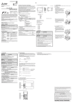
10.4 Troubleshooting Flowchart
1
The figure below shows troubleshooting for when the IP address storage area cannot be written or cleared
using the IP address change function.
oFor details on special devices, refer to Appendix A.
oFor details on error code, refer to Subsection 10.3.5.
Introduction
10.4.2 IP address change function error
2
Specification
In the case IP address storage area cannot be written to
Cannot write to IP address
storage area.
3
NO
Turn ON the IP address storage area write
request M8492.
NO
Turn OFF the PLC power supply, and then
turn ON the PLC power supply.
NO
Confirm the error code for IP address
storage area write D8498.
System
Configuration
IP address
storage area write completion
M8493 is ON.
YES
4
YES
5
Error code: 100
Reexamine the set value of D8492 to D8497.
The input format is hexadecimal. For the
setting range, refer to Section 6.5.
YES
YES
NO
6
Introduction of
Functions
PLC power
supply was turned OFF
during IP address storage
area write.
Wiring
PLC power supply was
turned from OFF to ON.
The " " mark indicates
a reference destination
and reference manual.
Installation
IP address
storage area write error
M8494 is ON.
Shows the reference.
Error code: 200
Something may be malfunctioning inside the PLC.
Error code: 1001
The PLC may be damaged if the situation is
not improved by writing again.
7
Communication
Using
MC Protocol
Confirm the error code for IP address storage area write D8498.
Error code: 1000
Do not turn the PLC power supply OFF during write, and try again.
8
Data monitoring
function
9
The Operation
of GX Works2
10
Troubleshooting
167
The above is different from the actual page, as it is provided for explanation only.
12
1 Introduction
FX3U-ENET-ADP User's Manual
1.1 Outline
1
Introduction
2
Outline
1.1.1
Overview of the Ethernet adapter
Network Range (Only within LAN)
4
Installation
The FX3U-ENET-ADP is an Ethernet adaptor of 10BASE-T/100BASE-TX for FX3S/FX3G/FX3GC/FX3U/FX3UC
PLCs, and can be connected to a high-order system such as personal computer using the TCP/IP or UDP
communication protocol.
3
System
Configuration
This manual provides information on the specifications of the FX3U-ENET-ADP Ethernet communication
special adapter (hereinafter called FX3U-ENET-ADP or the Ethernet adapter), as well as the procedures
before starting operation, the control procedures and data communication method for communicating with
external devices, and troubleshooting.
When the program examples introduced in this manual are applied to an actual system, examine the safety of
the control in the target system before use.
Specification
1.1
Introduction
1.
Router
5
Wiring
Hub
SNTP server
6
Introduction of
Functions
External device
Local station
7
External device
Communication
Using
MC Protocol
GX Works2
8
Data monitoring
function
9
The Operation
of GX Works2
10
Troubleshooting
13
1 Introduction
FX3U-ENET-ADP User's Manual
1.1.2
1.1 Outline
Features of the Ethernet adapter
The Ethernet adapter has the following features.
1) Users can read and write data and programs from/to the PLC using MELSOFT products such as GX
Works2 within the company LAN, etc.
2) Users can develop custom software to communicate with the PLC by using MC (MELSEC
Communication) protocol (A-compatible 1E frame subset, for details, refer to user's manual). (TCP/IP or
UDP/IP)
3) The FX3U-ENET-ADP can be connected directly (simple connection) to GX Works2 with only one
Ethernet cable without using the hub.
4) Users can search "FX3U-ENET-ADP + Main unit" connected in the network using the find CPU function of
GX Works2.
5) The FX3U-ENET-ADP can automatically set the time of the main unit using the time setting function.
6) The FX3U-ENET-ADP parameters can be set easily using GX Works2.
7) The diagnostic functions of GX Works2 enables easy diagnostics and troubleshooting of the FX3U-ENETADP.
8) Users can monitor the information and device values stored in the main unit and FX3U-ENET-ADP from
the browser in the personal computer using the data monitoring function.
1.1.3
Ethernet related term
1) TCP (Transmission Control Protocol)
This protocol guarantees data credibility and reliability in communication between a personal computer/
work station and PLC that are connected via network, and provides the following functions:
- Creates a logical connection by establishing a connection (logical line) as if a dedicated line was
created between external devices.
- Up to 4 connections can be established and used at the same time in the Ethernet adapter.
- Data reliability is maintained by sequence control using the sequence numbers, the data
retransmission function and check sum.
- Communication data flow can be controlled by Windows operations.
2) UDP (User Datagram Protocol)
This protocol may not guarantee data credibility or reliability in communication between a personal
computer/work station and PLC that are connected via network. Thus, even if the data does not reach the
target node, it will not be retransmitted.
- Because it is connectionless, communication efficiency is much improved than TCP/IP.
- A check sum is used to increase the reliability of the communication data.
When greater reliability must be maintained, a user application or TCP should be used for the retrying
operation.
3) IP (Internet Protocol)
- Communication data is sent and received in datagram format.
- Communication data can be divided and reassembled.
- Routing option is not supported.
4) ARP (Address Resolution Protocol)
- This protocol is used to get the Ethernet physical addresses from the IP addresses.
5) ICMP (Internet Control Message Protocol)
- This protocol is used to exchange errors which occur on an IP network and various information related
to the network.
- Provides a function to transmit IP error messages.
- Refer to Appendix E-6 for information regarding the types of ICMP supported.
14
1 Introduction
FX3U-ENET-ADP User's Manual
1.1 Outline
1
Introduction
2
Specification
3
System
Configuration
4
Installation
5
Wiring
6) Flag bit of TCP/IP (SYN, ACK, PSH, FIN, RST, and URG)
In communication using TCP, these flag bits indicate segments where connection/disconnection or
response confirmation is executed or emergency data is included.
a) SYN (Synchronized Flag)
When this bit is ON (1), it indicates that the initial sequence number value is set in the sequence
number field.
This bit is used when the connection is newly opened.
b) ACK (Acknowledgment Flag)
When this bit is ON (1), it indicates that ACK (confirmation response number) field is valid.
It also indicates that this segment includes the information on response confirmation.
When this bit is OFF (0), it indicates that ACK (confirmation response number) field is invalid.
c) PSH (Push Flag)
When this bit is ON (1), the host that has received this segment sends the data to the upper
application with high priority.
This bit is to be turned ON when the data should be sent to an external device as soon as possible.
When this bit is OFF (0), the timing when the received data is sent to the upper application depends
on the TCP layer of the receiving side.
d) FIN (Fin Flag)
When this bit is ON (1), it indicates that there is no more data to be sent from the segment source and
that the send source wants to disconnect.
However, data still can be received from the external device.
The connection is on until the segment whose FIN bit is ON is received from the external device.
e) RST (Reset Flag)
When this bit is ON (1), the host from which the segment has sent disconnects unilaterally (forcibly).
Disconnection by this method is used when an unrecoverable error with the normal method has
occurred or when the host has been restored after being down.
f) URG (Urgent Flag)
When this bit is ON (1), it indicates that this data segment includes the emergency data flag.
6
Introduction of
Functions
7
Communication
Using
MC Protocol
8
Data monitoring
function
9
The Operation
of GX Works2
10
Troubleshooting
15
1 Introduction
FX3U-ENET-ADP User's Manual
1.2
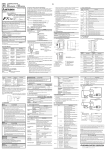
1.2 External Dimensions and Part Names
External Dimensions and Part Names
[3]
[4] [5]
90(3.55″)
98(3.86″)
(mounting hole pitch)
106(4.18″)
[2]
[1]
[6]
[7]
20.5
(0.81″)
7(0.28″)
81.5(3.21″)
[8]
23(0.91″)
[9]
Unit: mm(inches)
MASS(Weight): 0.1kg(0.22lbs)
DIN rail mounting groove
(DIN rail: DIN46277, 35mm (1.38") width)
[6]
Special adapter connector
[2]
Nameplate
[7]
10BASE-T/100BASE-TX connector (RJ45)
[3]
Direct mounting hole 2 holes of φ4.5 (0.18")
(mounting screw: M4 screw)
[8]
External ground terminal (M2.5 terminal block screw)
[4]
Status LEDs
[9]
DIN rail mounting hook
[5]
Special adapter fixing hook
[1]
1.3
Pin Configuration
The pin configuration of FX3U-ENET-ADP RJ45 type modular jack is as follows:
8
16
1
Pin No.
Signal
Direction
1
TD+
Out
2
TD-
Out
3
RD+
In
4
Not used
-
5
Not used
-
6
RD-
In
7
Not used
-
8
Not used
-
Contents
+ side of sending data
- side of sending data
+ side of receiving data
- side of receiving data
1 Introduction
FX3U-ENET-ADP User's Manual
1
Power and Status LEDs
LED
Color
POWER
Green
100M
Green
SD/RD
Green
OPEN
ON
Power is on
OFF
Power is off
ON
100Mbps communication
OFF
10Mbps communication or not connected
ON
Data being sent or received.
OFF
Data is not sent or received.
ON
Setting errors, hardware errors, etc.
Flicker
3
Communication errors
OFF
Setting normal, communication normal
ON*1
TCP/IP: 1 or more connections are established.
UDP: 1 or more connections are open.
OFF
TCP/IP: All connections are unestablished.
UDP: All connections are closed.
Green
2
4
In direct connection (simple connection), "OPEN" LED does not turn on.
Installation
*1.
Red
Description
System
Configuration
ERR.
Status
Specification
LED
display
Introduction
1.4
1.4 Power and Status LEDs
5
Wiring
6
Introduction of
Functions
7
Communication
Using
MC Protocol
8
Data monitoring
function
9
The Operation
of GX Works2
10
Troubleshooting
17
2 Specification
FX3U-ENET-ADP User's Manual
2.
Specification
DESIGN PRECAUTIONS
•
Make sure to include the following safety circuits outside the PLC to ensure safe system operation even during external power supply
problems or PLC failure.
Otherwise, malfunctions may cause serious accidents.
1) Above all, the following components should be included: an emergency stop circuit, a protection circuit, an interlock circuit for
opposite movements (such as normal vs. reverse rotation), and an interlock circuit (to prevent damage to the equipment at the
upper and lower positioning limits).
2) Note that when the PLC main unit detects an error during self diagnosis, such as a watchdog timer error, all outputs are turned off.
Also, when an error that cannot be detected by the PLC main unit occurs in an input/output control block, output control may be
disabled.
External circuits and mechanisms should be designed to ensure safe machinery operation in such cases.
DESIGN PRECAUTIONS
•
Observe the following items. Failure to do so may cause incorrect data-writing through noise to the PLC and result in PLC failure,
machine damage or other accident.
1) Do not bundle the control line together with or lay it close to the main circuit or power line.
Noise may cause malfunctions.
As a guideline, lay the control line at least 100mm (3.94") or more away from the main circuit or power line.
2) Ground the shield wire or shield of a shielded cable. Do not use common grounding with heavy electrical systems.
STARTUP AND
MAINTENANCE
PRECAUTIONS
•
•
•
Do not touch any terminals or connector while the PLC's power is on.
Doing so may cause electrical shock or malfunctions.
Before cleaning or retightening screws, externally cut off all phases of the power supply.
Failure to do so may cause malfunction or failure of this adapter. When the screws are tightened insufficiently, they may fall out and
cause a shortcircuit or malfunction. When tightened too much, the screws or the adapter may be damaged, resulting in short-circuit, or
malfunction.
When controlling the PLC (especially when changing data, the program or changing the operating conditions) during operation,
ensure that it is safe to do so.
STARTUP AND
MAINTENANCE
PRECAUTIONS
•
•
•
Do not disassemble or modify the adapter.
Doing so may cause fire, equipment failures, or malfunctions.
For repair, contact your local Mitsubishi Electric representative.
The adapter case is made of resin. If dropped or subjected to strong impact, the adapter may be damaged.
When this adapter is installed or removed from the panel, make sure to externally cut off all phases of the power supply. Failure to do
so may cause malfunction or failure of this adapter.
DISPOSAL PRECAUTIONS
•
Please contact a certified electronic waste disposal company for the environmentally safe recycling and disposal of your device.
TRANSPORTATION AND
STORAGE PRECAUTIONS
•
18
The product is a precision instrument. During transportation, avoid any impacts. Failure to do so may cause failures in the product.
After transportation, verify the operations of the product.
2 Specification
FX3U-ENET-ADP User's Manual
1
General Specifications
Introduction
2.1
2.1 General Specifications
For items not listed below, specifications are the same as those of the PLC main unit.
For general specifications, refer to the manual (Hardware Edition) of the PLC main unit.
Item
500 V AC for one minute
Insulation resistance
5M
or more by 500 V DC Megger
Between PLC all terminals and ground terminal
Power Supply Specifications
3
Specification
Adapter driving power supply
30mA / 5V DC
5V DC power is supplied internally from the main unit.
Permitted instantaneous power failure time
Same as connected PLC
System
Configuration
Item
2.3
Specification
2.2
2
Specification
Dielectric withstand voltage
4
Communication Specification
Transmission specifications
Specification
Data transmission speed
100Mbps/10Mbps
Communication method
Full-duplex/Half-duplex
Base band
Maximum segment length
100m (328’1")
10BASE-T
Cascade connection maximum 4 stages*1
100BASE-TX
Cascade connection maximum 2 stages*1
5
Wiring
Transmission method
Maximum number of
nodes/connection
Connector
Installation
Item
RJ45
*1.
Caution
6
Introduction of
Functions
The value indicates the number of connectable stages when the repeater hub is used.
Contact the manufacturer of the switching hub for the number of connectable stages when using the
switching hub.
When connecting Ethernet adapter to a network, either a 10BASE-T or 100BASE-TX can be used.
The Ethernet adapter can be connected directly to the personal computer without using the hub.
The ports must comply with the IEEE802.3 10BASE-T or IEEE802.3 100BASE-TX standards.
7
8
Data monitoring
function
• The module operation is not guaranteed if any of the following connections are used.
- Connections using the Internet (general public line) (Connections using Internet connection service
provided by Internet service providers and telecommunications carriers)
- Connections using devices in which a firewall is installed
- Connections using broadband routers
- Connections using wireless LAN
Communication
Using
MC Protocol
• The Ethernet adapter detects whether it is 10BASE-T or 100BASE-TX, and full-duplex or half-duplex
transmission mode according to the hub. (auto detection function)
For connection to the hub without the auto detection function, set half-duplex mode on the hub side.
9
The Operation
of GX Works2
10
Troubleshooting
19
2 Specification
FX3U-ENET-ADP User's Manual
2.4
2.4 Performance Specification
Performance Specification
Item
Specification
MELSOFT connections
Communication Using MC Protocol
MELSOFT Direct Connection (Simple Connection)
Find CPU function
Functions
Time setting function*1
Diagnostics function from MELSOFT
Data monitoring function
Number of simultaneously open connections
MELSOFT connection + MC protocol + Data monitoring <= 4
allowed
Number of connectable units to the main unit 1 unit*2
2.5
*1.
The time setting function (SNTP client) is enabled only after the trigger condition is established.
*2.
The Ethernet adapter occupies 1 communication channel in the same way as communication
expansion boards and other communication special adapters.
Communication function and corresponding equipment
This section explains with which external devices data communication can be performed and which additional
functions can be used for each function.
1) Ability to communicate with external devices using various functions
The following table lists with which external devices communication is possible using various functions.
External device
Function
Personal computer
Personal computer
FX3U-ENET-ADP
FX3U-ENET-ADP
FX3U-ENET-ADP
FX3U-ENET-ADP
Communication using MC protocol
: Can communicate
: Cannot communicate
2) Relationship with additional functions
The following table lists the relationship between functions and any additional functions that can be used.
Additional function
Function
Communication using MC protocol
Router relay
communication
(router relay function)
Existence check of
external device
Communication method
TCP/IP
(TCP only)
: Available
20
UDP/IP
: Not available
3 System Configuration
FX3U-ENET-ADP User's Manual
3.1 General Configuration
1
Introduction
3.
System Configuration
2
This section explains the system configurations that may be used with the Ethernet adapter.
Specification
3.1
General Configuration
MELSOFT connection
3
SNTP server
System
Configuration
Connection of user application
and other company device
(MC protocol)
External device
(Client)
4
Installation
FX3S/FX3G/FX3GC/FX3U/FX3UC PLC
5
Wiring
Maintenance
GX Works2, others
(MELSOFT connection)
FX3U-ENET-ADP
6
Component list
Model name
Introduction of
Functions
Part name
Remarks
Ethernet adapter
FX3U-ENET-ADP
-
PLC
FX3S/FX3G/FX3GC/FX3U/FX3UC PLC
-
PC software
GX Works2
PLC programming software.
This software writes various settings for the Ethernet adapter.
-
HUB*1
-
SNTP server*2
-
External device
-
Ethernet cable
-
7
-
Communication
Using
MC Protocol
Personal computer
Use an industrial product.
MC protocol conforming device
10BASE-T: Category 3 or higher (STP cable*3)
8
100BASE-TX: Category 5 or higher (STP cable*3)
Data monitoring
function
*1. A hub is not used in direct connection (simple connection) etc.
*2. Time information server.
*3. Shielded twisted pair cable.
9
The Operation
of GX Works2
10
Troubleshooting
21
3 System Configuration
FX3U-ENET-ADP User's Manual
3.2
3.2 Devices Required for Network Configuration
Devices Required for Network Configuration
This section explains the devices that are required to configure a network.
Network installation work requires sufficient safeguards; ask a network specialist for installation.
When connecting the Ethernet adapter to a network, either 10BASE-T or 100BASE-TX can be used.
The Ethernet adapter detects whether it is 10BASE-T or 100BASE-TX, and full-duplex or half-duplex
transmission mode according to the hub. (Auto detection function)
For connection to the hub without the auto detection function, set half-duplex mode on the hub side.
1) Connection using 100BASE-TX
Use devices that satisfy the standards of IEEE802.3 and 100BASE-TX.
• Shielded twisted pair cable (STP cable), category 5 or higher
Use a straight cable for connection between a hub and the Ethernet adapter.
(A cross cable can also be used when connecting the Ethernet adapter directly to the external device,
not through a hub.)
• RJ45 plug
• 100Mbps hub
2) Connection using 10BASE-T
Use devices that satisfy the standards of IEEE802.3 and 10BASE-T.
Use devices that satisfy the standards of IEEE802.3 and 100BASE-TX.
• Shielded twisted pair cable (STP cable), category 3 or higher
Use a straight cable for connection between a hub and the Ethernet adapter.
(A cross cable can also be used when connecting the Ethernet adapter directly to the external device,
not through the hub.)
• RJ45 plug
• 10Mbps hub
3.3
Applicable Systems
3.3.1
Applicable PLC
Model name
FX3S Series
PLC*1*2
Applicability
Ver. 1.00 or later
FX3G/FX3GC Series PLC*1
Ver. 2.00 or later
PLC*3
Ver. 3.10 or later
FX3U/FX3UC Series
Only one FX3U-ENET-ADP unit can be connected to a main unit.
The version number can be checked by reading the last three digits of device D8001 or D8101.
*1. A connector conversion adapter is required to connect the FX3U-ENET-ADP with FX3S/FX3G PLCs.
*2. The FX3S PLC is supported by FX3U-ENET-ADP Ver. 1.20 or later.
*3. An expansion board is required to connect the FX3U-ENET-ADP with FX3U/FX3UC-32MT-LT(-2) PLCs.
3.3.2
Applicable Software
1. GX Works2
Use the following version when setting the Ethernet adapter or using the MELSOFT connection function.
Model name
Applicable GX Works2 version
Applicable FX3U-ENET-ADP version
Ver. 1.492N or later
Ver. 1.20 or later
Ver. 1.87R or later
Ver. 1.00 or later
Ver. 1.73B or later*4
Ver. 1.00 or later
FX3S PLC
• SW DNC-GXW2-E
FX3G, FX3GC PLC
• SW DNC-GXW2-E
FX3U, FX3UC PLC
• SW DNC-GXW2-E
*4. GX Works2 Ver. 1.86Q or earlier does not support the data monitoring function setting.
22
3 System Configuration
FX3U-ENET-ADP User's Manual
3.4 Connection with PLC
1
Introduction
Caution
• If an older version is used, programming will not be possible.
• In order to set up the Ethernet adapter via GX Works2 Ver. 1.73B or later and earlier than 1.91V,
FX Configurator-EN must be installed.
Connection with PLC
1. FX3S/FX3G/FX3U/FX3UC-32MT-LT(-2) PLC
Other special
adapters
3
System
Configuration
The Ethernet adapter connects to a FX3S/FX3G/FX3GC/FX3U/FX3UC PLC via a special adapter connector.
Only one Ethernet adapter can be connected to the FX 3S /FX 3G /FX 3GC /FX3U /FX 3UC PLC. A connector
conversion adapter is required to connect the Ethernet adapter with the FX 3S/FX3G PLCs. An expansion
board is required to connect the Ethernet adapter with the FX3U/FX3UC-32MT-LT(-2) PLCs.
The Ethernet adapter must be connected at the last stage (left end) of adapters for the FX3S/FX3G/FX3GC/
FX3U/FX3UC PLC.
Specification
3.4
2
4
Expansion board
Installation
Main unit
5
Wiring
FX3U-ENET-ADP
6
2. FX3GC/FX3UC(D, DS, DSS) PLC
Introduction of
Functions
Other special
adapters
Main unit
7
Communication
Using
MC Protocol
8
FX3U-ENET-ADP
Data monitoring
function
3.5
Assignment of channels
9
The Operation
of GX Works2
The Ethernet adapter is a communication special adapter for PLCs, and channel numbers (such as CH1 and
CH2) are automatically assigned starting from the adapter nearest the main unit. This channel number is
used in GX Works2.
Only one Ethernet adapter can be connected at the last stage (left end) of adapters. When another
communication expansion board/communication special adapter (including the FX3U-8AV-BD and FX3U-CFADP) is connected to the FX3U/FX3UC PLC, "CH2" is assigned to the Ethernet adapter.
The channel number is assigned as shown following page.
10
Troubleshooting
23
3 System Configuration
FX3U-ENET-ADP User's Manual
3.5 Assignment of channels
1. FX3S PLC (CH1)
CH1
FX3U-ENET-ADP
Analog
FX3S-CNV-ADP
special adapter
FX3S Main unit
Caution on using the Ethernet adapter
The Ethernet adapter is a communication special adapter, and occupies 1 communication channel.
Accordingly, any other communication function expansion board/communication special adapter cannot be
connected to the FX3S PLC when the Ethernet adapter is used.
2. FX3G PLC
• 14/24 point type (CH1)
CH1
FX3U-ENET-ADP
Analog
FX3G-CNV-ADP
special adapter
FX3G Main unit
(14/24 point type)
• 40/60 point type
- When not using other communication expansion board/communication special adapter (CH1)
CH1
FX3U-ENET-ADP
Analog
FX3G-CNV-ADP
special adapter
FX3G Main unit
(40/60 point type)
- When using other communication expansion board (CH1)
CH1
Analog
FX3U-ENET-ADP
FX3G-CNV-ADP
special adapter
FX3G Main unit
(40/60 point type)
BD2 Connector
(CH2)
Communication expansion board
(including the FX3G-8AV-BD)
- When using other communication special adapter (CH2)
CH2
(CH1)
FX3U-ENET-ADP
Communication
special adapter
FX3G-CNV-ADP
FX3G Main unit
(40/60 point type)
Caution on using the Ethernet adapter
The Ethernet adapter is a communication special adapter, and occupies 1 communication channel.
When the Ethernet adapter is used, only one other communication expansion board/communication special
adapter (including the FX3G-8AV-BD) can be connected to the FX3G PLC(40/60 point type).
24
3 System Configuration
FX3U-ENET-ADP User's Manual
3.5 Assignment of channels
1
Introduction
3. FX3GC PLC
• When not using other communication special adapter (CH1)
CH1
Analog
special adapter
2
FX3GC Main unit
Specification
FX3U-ENET-ADP
• When using other communication special adapter (CH2)
CH2
Analog
Communication
special adapter special adapter
System
Configuration
FX3U-ENET-ADP
3
(CH1)
FX3GC Main unit
4
The Ethernet adapter is a communication special adapter, and occupies 1 communication channel.
When the Ethernet adapter is used, only one other communication special adapter can be connected to the
FX3GC PLC.
Installation
Caution on using the Ethernet adapter
5
4. FX3U/FX3UC-32MT-LT(-2) PLC
Wiring
• When not using other communication expansion board/communication special adapter (CH1)
CH1
FX3U-ENET-ADP
6
FX3U, FX3UC-32MT-LT(-2)
Main unit
Introduction of
Functions
Analog
Analog
FX3U-CNV-BD
special adapter special adapter
• When using other communication expansion board/communication special adapter (CH2)
FX3U-ENET-ADP
7
(CH1)
Analog
special adapter
Communication
expansion
board
Communication
Using
MC Protocol
CH2
FX3U, FX3UC-32MT-LT(-2)
Main unit
8
9
The Operation
of GX Works2
The Ethernet adapter is a communication special adapter, and occupies 1 communication channel.
When the Ethernet adapter is used, only one other communication expansion board/communication special
adapter (including the FX3U-8AV-BD and FX3U-CF-ADP) can be connected to the FX3U/FX3UC-32MT-LT(-2)
PLC.
Data monitoring
function
Caution on using the Ethernet adapter
10
Troubleshooting
25
3 System Configuration
FX3U-ENET-ADP User's Manual
3.5 Assignment of channels
5. FX3UC(D, DS, DSS) PLC
• When not using other communication special adapter (CH1)
CH1
FX3U-ENET-ADP
Analog
special adapter
FX3UC(D, DS, DSS)
Main unit
• When using other communication special adapter (CH2)
CH2
(CH1)
FX3U-ENET-ADP
Analog
Communication
Analog
special adapter special adapter special adapter
FX3UC(D, DS, DSS)
Main unit
Caution on using the Ethernet adapter
The Ethernet adapter is a communication special adapter, and occupies 1 communication channel.
When the Ethernet adapter is used, only one other communication special adapter (including the FX3U-CFADP) can be connected to the FX3UC(D, DS, DSS) PLC.
26
4 Installation
FX3U-ENET-ADP User's Manual
1
Introduction
4.
Installation
2
•
Specification
INSTALLATION
PRECAUTIONS
Make sure to cut off all phases of the power supply externally before attempting installation work.
Failure to do so may cause electric shock.
3
•
•
•
•
4
Installation
•
•
Use the product within the generic environment specifications described in PLC main unit manual (Hardware Edition).
Never use the product in areas with excessive dust, oily smoke, conductive dusts, corrosive gas (salt air, Cl2, H2S, SO2, or NO2),
flammable gas, vibration or impacts, or expose it to high temperature, condensation, or rain and wind.
If the product is used in such conditions, electric shock, fire, malfunctions, deterioration or damage may occur.
Do not touch the conductive parts of the product directly.
Doing so may cause device failures or malfunctions.
Install the product securely using a DIN rail or mounting screws.
Install the product on a flat surface.
If the mounting surface is rough, undue force will be applied to the PC board, thereby causing nonconformities.
When drilling screw holes or wiring, make sure that cutting and wiring debris do not enter the ventilation slits.
Failure to do so may cause fire, equipment failures or malfunctions.
Connect the FX3U-ENET-ADP securely to special adapter connector.
Loose connections may cause malfunctions.
System
Configuration
INSTALLATION
PRECAUTIONS
5
Wiring
6
Introduction of
Functions
7
Communication
Using
MC Protocol
8
Data monitoring
function
9
The Operation
of GX Works2
10
Troubleshooting
27
4 Installation
FX3U-ENET-ADP User's Manual
4.1
4.1 FX3U-ENET-ADP Connection
FX3U-ENET-ADP Connection
An expansion board or connector conversion adapter should be installed before connecting the Ethernet
adapter. An expansion board or connector conversion adapter is not required when the Ethernet adapter is
connected to a FX3GC/FX3UC(D, DS, DSS) PLC.
This section explains an example where the Ethernet adapter is connected to a FX3U PLC. For connection to
other PLCs, refer to the manual (Hardware Edition) of the connected PLC.
1
Remove the special adapter connector cover
(A in the figure on the right) from the expansion
board.
It is assumed that an expansion board has been installed in
advance. For the expansion board installation method, refer
to the respective PLC manual.
2
→ Refer to FX3U Hardware Edition
2
Slide the special adapter connecting hooks
(B in the figure on the right) of the main unit
upwards.
1
B
2
A
B
3
4
Connect the Ethernet adapter (C
in the figure on the right) to the
main unit as shown in the figure
on the right.
Slide the special adapter
connecting hooks (B in the figure
on the right) of the main unit
downwards to secure the
Ethernet adapter (C in the figure
on the right).
C
B
4
4
3
3
3
B
Caution on connection
Only one FX3U-ENET-ADP unit can be connected in the final stage (leftmost position) of the main unit, special
adapter, etc.
Connect all the high-speed I/O special adapters before connecting other special adapters when they are used
in combination.
Do not connect a high-speed I/O special adapter on the left side of any special adapters other than other
high-speed I/O special adapters.
28
4 Installation
FX3U-ENET-ADP User's Manual
1
DIN rail mounting
The Ethernet adapter may be mounted on a 35mm (1.38") wide DIN46277 (DIN rail).
Connect the Ethernet adapter to the PLC main unit before attaching the Ethernet adapter to a DIN rail.
This section explains an example where the Ethernet adapter is connected to a FX3U PLC. For the DIN rail
mounting method for other PLCs, refer to the manual (Hardware Edition) of the connected PLC.
2
Specification
5
Introduction
4.2
4.2 DIN rail mounting
Push out all DIN rail mounting hooks (A
in the figure on the right).
It is assumed that the Ethernet adapter has been
connected in advance. For the Ethernet adapter
connection method, refer to the following.
3
System
Configuration
→ Refer to Section 4.1
A
1
A
1
A
1
4
Push the product onto the DIN rail.
2
5
B
Wiring
7
Fit the upper edge (B in the figure on the right) of the DIN
rail mounting groove onto the DIN rail.
Installation
6
3
Lock the DIN rail mounting hooks (A in the following figure) while pressing
the PLC against the DIN rail.
Introduction of
Functions
8
6
7
Communication
Using
MC Protocol
A
4
A
4
A
8
4
Data monitoring
function
9
The Operation
of GX Works2
10
Troubleshooting
29
4 Installation
FX3U-ENET-ADP User's Manual
4.3
4.3 Direct mounting
Direct mounting
When the Ethernet adapter is connected to a FX3S/FX3G/FX3U PLC, the Ethernet adapter may be mounted
directly on a panel surface using screws. The direct mounting method is not available when the Ethernet
adapter is connected to a FX3GC/FX3UC PLC. Connect the Ethernet adapter to the main unit before attaching
it to the panel surface.
For mounting, refer to the following manual.
→ Refer to FX3S Hardware Edition
→ Refer to FX3G Hardware Edition
→ Refer to FX3U Hardware Edition
1
Create mounting holes in the
mounting surface according to the
external dimensions diagram.
A
2
Fit the Ethernet adapter to the
mounting holes and tighten with
M4 screws (A in the figure on the
right).
Also fit the main unit to the mounting holes
and tighten with M4 screws. For the main unit
connection method, refer to the following.
→ Refer to FX3S Hardware Edition
→ Refer to FX3G Hardware Edition
→ Refer to FX3U Hardware Edition
A
It is assumed that the Ethernet adapter has
been connected in advance.
For the Ethernet adapter connection method, refer to the following.
→ Refer to Section 4.1
For the screw positions and number of screws in the Ethernet adapter, refer to the dimensional
outline drawing as follows.
→ Refer to Section 1.2
For the screw positions and number of screws in the main unit, refer to the following manual.
→ Refer to FX3S Hardware Edition
→ Refer to FX3G Hardware Edition
→ Refer to FX3U Hardware Edition
30
5 Wiring
FX3U-ENET-ADP User's Manual
5.1 Grounding
1
Introduction
5.
Wiring
2
Specification
WIRING PRECAUTIONS
•
Make sure to cut off all phases of the power supply externally before attempting wiring work.
Failure to do so may cause electric shock or damage to the product.
3
•
•
•
Ground the cables as follows
• The grounding resistance should be 100
or less.
Other
equipment
PLC
Shared grounding
Good
PLC
Other
equipment
8
Common grounding
Not allowed
• The grounding point should be close to the Ethernet adapter, and all grounding wires should be as short as
possible.
(Ground terminal)
Content
Perform class D grounding.
(Grounding resistance: 100
9
The Operation
of GX Works2
Terminal block arrangement
Terminal name
7
Data monitoring
function
Independent grounding
Best
Other
equipment
6
Communication
Using
MC Protocol
• Independent grounding should be established whenever possible.
Independent grounding should be performed for best results.
When independent grounding is not configured, perform "shared grounding" as shown in the following
figure.
For details, refer to the manual (Hardware Edition) of the connected PLC.
PLC
5
Introduction of
Functions
Grounding
4
Wiring
5.1
or less) to the grounding terminal on the FX3U-ENET-ADP with a wire of
cross-sectional area 0.5 to 1.5 mm2. Do not use common grounding with heavy electrical systems (refer to the Section 5.1).
When drilling screw holes or wiring, make sure that cutting and wiring debris do not enter the ventilation slits.
Failure to do so may cause fire, equipment failures or malfunctions.
Make sure to properly wire to the terminal block (European type) in accordance with the following precautions.
Failure to do so may cause electric shock, equipment failures, a short-circuit, wire breakage, malfunctions, or damage to the product.
- The disposal size of the cable end should follow the dimensions described in the manual.
- Tightening torque should follow the specifications in the manual.
- Twist the end of strand wire and make sure that there are no loose wires.
- Do not solder-plate the electric wire ends.
- Do not connect more than the specified number of wires or electric wires of unspecified size.
- Affix the electric wires so that neither the terminal block nor the connected parts are directly stressed.
Make sure to observe the following precautions in order to prevent any damage to the machinery or accidents due to abnormal data
written to the PLC under the influence of noise:
1) Do not bundle the main circuit line together with or lay it close to the main circuit, high-voltage line or load line.
Otherwise, noise disturbance and/or surge induction are likely to take place. As a guideline, lay the control line at least 100mm
(3.94") or more away from the main circuit or high-voltage lines.
2) Ground the shield wire or shield of the shielded cable at one point on the PLC. However, do not use common grounding with
heavy electrical systems.
Installation
•
Perform class D grounding (grounding resistance: 100
System
Configuration
WIRING PRECAUTIONS
or less)
10
Troubleshooting
31
5 Wiring
FX3U-ENET-ADP User's Manual
5.2 Screw Size and Tightening Torque
Grounding wiring
Example usage of FX3U
D Grounding
(100Ω or less)
Ethernet
modular jack
(RJ45)
FX3U
FX3U-ENET-ADP
Applicable cables
Electric wire size
0.5 to 1.5 mm2 (AWG 20 to 16)
• When using a stranded cable or solid cable as it is
- Twist the end of the stranded cable so that loose wires will not stick out.
- Do not solder-plate the end of the cable.
Approx. 8 mm
(0.31")
5.2
Screw Size and Tightening Torque
The grounding terminal of the Ethernet adapter is a M2.5 screw.
Set the tightening torque to 0.4 to 0.5 N·m.
Terminal screws must be secured to prevent a loose connection thus avoiding a malfunction.
Failure to do so may cause equipment failures or malfunctions.
Caution
When tightening a grounding terminal, use a screwdriver suitable for the terminal screw. The screwdriver
which does not suit the thread groove is used, tightening torque will not be able to be achieved. To achieve
the appropriate tightening torque shown in the above, use the following screwdriver or an appropriate
replacement.
<Reference>
32
Manufacturer
Model name
Model number
Weidmuller Interface GmbH & Co. KG
SDIK PH0
9008560000
Weidmuller Interface GmbH & Co. KG
SD 0.6 3.5 100
9008330000
5 Wiring
FX3U-ENET-ADP User's Manual
1
Connecting to the Network
Introduction
5.3
5.3 Connecting to the Network
The following explains how to connect the Ethernet adapter to 10BASE-T/100BASE-TX networks.
Pay close attention to safety and use the Ethernet adapter properly.
2) Use a connection cable conforming to the standards shown in Subsection 5.3.1.
Cautions regarding powering the hub, PLC and Ethernet adapter simultaneously.
5.3.1
Applicable cable
The following should be used for the Ethernet cable.
Item
100BASE-TX
4
Specification
Installation
10BASE-T
Cable conforming to Ethernet standard practice:
Category 3 or higher (STP cable*1)
Cable conforming to Ethernet standard practice:
Category 5 or higher (STP cable*1)
*1. Shielded twisted pair cable.
5
Wiring
• A straight cable is used. A cross cable can also be used when using direct connection (simple connection)
between the personal computer and the Ethernet adapter.
5.3.2
3
System
Configuration
On some hubs, for a fixed period of time immediately after powering up, even if packets are sent from the
Ethernet device, there are cases when packets are not sent to the external device. In this case, create a
sequence program that waits a sufficient amount of time after powering up before sending packets.
2
Specification
1) Sufficient network knowledge and safety precautions are required when installing 10BASE-T or
100BASE-TX networks. Consult a specialist when connecting cable terminals or installing trunk line
cables, etc.
Connecting to the 10BASE-T/100BASE-TX network
6
Introduction of
Functions
This section explains how to connect the Ethernet adapter to the 10BASE-T, 100BASE-TX network.
The following shows the connection diagram for the twisted paid cable.
7
RJ45 type modular
Communication
Using
MC Protocol
Shielded twisted pair cable
(Category 3, 5 or higher)
8
Data monitoring
function
RJ45 type modular jack
<Operating procedure>
(Step 1) Connect the twisted pair cable to the hub.
(Step 2) Connect the twisted pair cable to the Ethernet adapter.
9
2) For 10BASE-T or 100BASE-TX connection required devices and a sample system configuration, refer to
Section 3.2.
The Operation
of GX Works2
1) The Ethernet adapter detects whether it is 10BASE-T or 100BASE-TX, and in full-duplex or half-duplex
transmission mode automatically according to the hub. (Auto detection function)
For connection to a hub without the auto detection function, set the half-duplex mode on the hub side.
10
Troubleshooting
33
6 Introduction of Functions
FX3U-ENET-ADP User's Manual
6.
6.1
6.1 Functions List
Introduction of Functions
Functions List
This section shows a list of Ethernet adapter functions.
Functions
MELSOFT connections
Description
Reference section
This function allows communication with a MELSOFT product (such as GX Work2)
on a LAN (such as company LAN).
Subsection 6.2.1
Communication Using MC This function reads/writes the PLC data from/to an external device, and supports
Protocol
subsets of the A-compatible 1E frame.
Chapter 7
This function connects the Ethernet adapter attached to the main unit to a MELSOFT
MELSOFT Direct Connection product (such as GX Works2) with one Ethernet cable without using a hub, and
(Simple Connection)
enables communication when only the connection destination is specified. It is not
necessary to set the IP address.
Subsection 6.2.3
Find CPU function
This function searches (PLC CPUs connected to) Ethernet adapters connected to
the same hub as the personal computer using GX Works2, and enables selection of
a desired CPU from the list of found CPUs and acquisition of the IP address.
Subsection 6.2.4
Time setting function
This function accesses the time information server (SNTP server) connected to the
LAN, collects the time information, and automatically sets the time to the main unit.
Subsection 6.2.5
Parameter setting function
This function sets parameters of the Ethernet adapter from GX Works2 via the main
unit.
Subsection 6.2.6
from This function diagnoses the Ethernet adapter from GX Works2 via the main unit.
(Ethernet Diagnostics)
Subsection 6.2.7
IP address change function*1
This function sets the IP address of the Ethernet adapter from peripheral devices via
the main unit.
Subsection 6.2.8
Data monitoring function
This function monitors the information on the PLC main unit, device values and
Ethernet adapter from the browser in the personal computer.
Chapter 8
Diagnostics
MELSOFT
*1.
function
Only available for FX3G/FX3GC PLC Ver. 2.10 or later and FX3S PLC.
6.2
Details of functions
6.2.1
MELSOFT connections
This function allows communication with a MELSOFT product (such as GX Work2) in the LAN (such as
company LAN).
This function is equivalent to the communication function supported on the RS-422 port in the PLC main unit,
and provides the following:
• Reading, writing (including writing during RUN) and verification of programs
• Reading and test of devices in the PLC main unit (including buffer memories in special function blocks)
This function is activated when the open method of the connection No. used for the open setting is set to
"MELSOFT connections".
For operation of GX Works2, refer to Section 9.2.
6.2.2
Communication Using MC Protocol
For details of MC Protocol, refer to Chapter 7.
34
6 Introduction of Functions
FX3U-ENET-ADP User's Manual
1
MELSOFT Direct Connection (Simple Connection)
FX3S/FX3G/FX3GC/FX3U/FX3UC PLC
2
Specification
This function connects the Ethernet adapter attached to the main unit to a MELSOFT product (such as GX
Works2) with one Ethernet cable without using the hub.
The direct connection enables communication by only specifying the connection target. IP address setting is
not required.
For direct connection operation of GX Works2, refer to Subsection 9.5.1.
Introduction
6.2.3
6.2 Details of functions
3
System
Configuration
FX3U-ENET-ADP
Caution
• When the item "Disable direct connection to MELSOFT" is checked in the Ethernet port setting of the PLC
parameters, direct connection is disabled. Check this item to prevent illegal connections from remote
places.
• Do not configure direct connection in a system configuration that connects the Ethernet adapter with an
external device using a hub.
• When the FX3S/FX3G/FX3GC PLC (Ethernet adapter) is connected directly to the personal computer
(MELSOFT direct connection), a communication error may occur when the PLC memory clear operation is
executed due to the Windows firewall. In this case, open the Windows control panel, and specify the
MELSOFT product (such as GX Works2) as "Allowed program" or "Exception" in the security setting for
Windows firewall.
Find CPU function
Caution
• When the item "Do not respond to search for CPU on network" is checked in the Ethernet port setting of
the PLC parameters, the Ethernet adapter does not respond to search for CPU on the network.
8
Data monitoring
function
This function searches Ethernet adapters (connected to PLC main units) connected to the same hub as the
personal computer using GX Works2, and enables selection of a desired Ethernet adapter (PLC main unit)
from the list of found Ethernet adapters (PLC main units) and acquisition of the IP address.
For operation of GX Works2, refer to Subsection 9.5.2.
7
Communication
Using
MC Protocol
6.2.4
6
Introduction of
Functions
• Under the following conditions, direct connection communication may not be available. In that case, check
the setting of the Ethernet adapter, main unit and/or personal computer.
- When all bits corresponding to "0" of the subnet mask in the personal computer are ON or OFF
- When all bits corresponding to the host address in each class of IP address in the personal computer
are ON or OFF
5
Wiring
• When two or more Ethernet ports are enabled in the network connections setting on the personal
computer, communication by direct connection is not possible. In the setting, leave only one Ethernet port
enabled for direct connection and disable the other Ethernet ports.
Installation
• When the Ethernet adapter is connected to the LAN line, do not set direct connection. It may increase the
load on the line and adversely affect communication or other devices.
4
9
• Ethernet adapter (PLC main unit CPU) connected via a router cannot be found.
• If Ethernet adapter (PLC main unit CPU) with the same IP address are found in the list, correct the
parameter settings of the Ethernet adapter side IP address. If communication is performed in this situation,
a communication error occurs.
• When "*****" is displayed as the comment, the keyword setting in the main unit is set to "Read and write
prohibited" or "All online operations prohibited".
35
10
Troubleshooting
• Search for CPU may be disabled when the scan time in the main unit is long. In such a case, make the
response waiting time longer on the search for CPU screen.
The Operation
of GX Works2
• Ethernet adapter (PLC main unit CPU) connected to a cascade connected hub are also found and
displayed in the list.
6 Introduction of Functions
FX3U-ENET-ADP User's Manual
6.2.5
6.2 Details of functions
Time setting function
The Ethernet adapter collects time information from a time information server connected to LAN (SNTP
server), making it possible to set the PLC main unit time automatically.
The time setting function queries the time information server to ask the time at the specified timing.
Also, it sets the time sent from the time information server as clock data of the main unit.
The time setting operation is executed based on the following timing.
• At PLC main unit power ON.
• Execution at a specified time interval (Execution interval)
• Execution at a specified time (Execution time)
• At special auxiliary relay ON.*1
*1.
The time setting function is valid when the special M bit (CH1: M8411, CH2: M8431) is ON. For details
of the special M bit, refer to Appendix A.
For operation of GX Works2, refer to Section 9.3.
SNTP server
Time inquiry
Server time is obtained
FX3S/FX3G/FX3GC/FX3U/FX3UC PLC
Time setting
FX3U-ENET-ADP
Time setting function settings
Setting
SNTP Function Setting
Description
Select whether or not to use the time setting function.
SNTP Server IP Address*2
Specify the SNTP server IP address.
Time Zone
Specify the time zone (GMT-12:00 to GMT+13:00) in which the time is to be synchronized.
Execute time setting at turn ON
Select whether or not to execute the time setting function when the PLC main unit is powered ON.
On-error Action
Select whether to stop or continue when a time setting error occurs when the PLC main unit is
powered ON.
Execution Interval*3
Select to execute the time setting function at a specified time interval. (1 to 1440 min)
Execution
Port No.
Time*3
Select to execute the time setting function at a specified time. (in increments of 30 minutes)
123 fixed value
*2. Set the SNTP server IP address upon consulting a network administrator (the person who plans the
network and manages IP addresses).
*3. One of the two options must be selected.
36
6 Introduction of Functions
FX3U-ENET-ADP User's Manual
6.2 Details of functions
1
• Do not turn ON M8015 (Clock stop and clock setting) in the PLC main unit while the time setting function is
used. Turning ON M8015 may cause errors in the Ethernet adapter.
• Do not set the time to the PLC main unit from peripheral equipment while the time setting function is used.
Setting the time may cause errors in the Ethernet adapter.
• A delay occurs with respect to the time as a result of the time required for communication with the SNTP
server.
Specify the closest personal computer for the SNTP server on the network.
• Communication timeout occurs 20 seconds after the time is inquired from the SNTP server (time
information server).
3
Initial
Pulse
SET
Time setting
execution
(CH1)
M8406
*1
RUN not Time setting
allowed execution
flag
(CH1)
M0
Time setting execution
turns on M0 (RUN not
allowed flag).
RUN not
allowed
flag
FNC232 D8411* 2
AND=
K1
Time setting
functional
operation
result (CH1)
RST
M0
5
Wiring
M0
M8406* 1
M0 (RUN not allowed flag)
is turned off when time
setting finishes.
RUN not
allowed
flag
P63
6
Time setting execution is
jumped to END.
Introduction of
Functions
FNC 00
CJ
4
Installation
Example program (In case of CH1)
System
Configuration
• If the power supply of the PLC is turned on in the RUN state when "Execute time setting at turn ON" is set
up, the RUN process and time setting will start simultaneously. If "Stop" is set up at "On-error Action", after
the PLC RUNs and executes sequence processing upon power ON, it may stop due to time setting error.
To avoid this, do not execute sequence processing until time setting has finished. Please refer to the
following example program.
M8002
2
Specification
• To use the time setting function, an SNTP server (time information server) is required on the LAN.
Introduction
Caution
Jumps to
END
7
Communication
Using
MC Protocol
User sequence processing
END
8
Data monitoring
function
*1. In case of channel 2, set to M8426.
*2. In case of channel 2, set to D8431.
9
The Operation
of GX Works2
10
Troubleshooting
37
6 Introduction of Functions
FX3U-ENET-ADP User's Manual
6.2.6
6.2 Details of functions
Parameter setting function
This function sets parameters of the Ethernet adapter from GX Works2 via the PLC main unit.
For details of operation setting, refer to Section 6.6. For details of open setting, refer to Section 6.11.
For operation of GX Works2, refer to Section 9.1 and Section 9.2.
List of parameter setting function settings
Setting
Channel
IP Address
Subnet Mask Pattern
Operation Setting
Default Router IP Address
Communication Data Code
Direct connection (simple connection)
Find CPU function
Protocol
Open System
Open Setting
Host Station Port No.
Destination IP Address
Destination Port No.
6.2.7
The diagnostics function from MELSOFT
This function diagnoses the Ethernet adapter from GX Works2 via the PLC main unit. (Ethernet Diagnostics)
For operation of GX Works2, refer to Section 9.6.
The diagnostics function list from MELSOFT
function
Description
Parameter status
IP address, Ethernet address, etc. are displayed.
Error history*1
Connection No., error code, port number, date, time, etc. are displayed.
Status of each connection
Host Station Port No., Destination IP Address, Destination Port No., newest error code, etc. are
displayed.
Access history*1
The date, time, connection No., Destination IP Address, etc. are displayed.
Status of each protocol
TCP packet, UDP packet, etc. are displayed.
Connection status
Full-duplex/Half-duplex, connection condition, and 10BASE-T/100BASE-TX are displayed.
Time setting status
The latest time setting time and the Acknowledge duration are displayed.
PING test
This test checks the presence of Ethernet module in the Ethernet line in which initialization is
completed or the presence of specified IP address.
*1. Log record setting is required in advance. For details of setting, refer to Section 9.4.
Caution
The error history, access history and time setting status are cleared when the power is turned from OFF to
ON, even if latched devices are set in the log record setting, if the PLC main unit is set to batteryless mode.
38
6 Introduction of Functions
FX3U-ENET-ADP User's Manual
1
IP address change function
D8492
D8493
D8494
D8495
D8497
IP address
Subnet
mask
pattern
Special data register
D8492
Default
router
IP address
D8493
D8494
D8495
Serial communication
(RS-422/232C)
D8496
D8497
IP address
IP address
Subnet
mask
pattern
Subnet
mask
pattern
Default
router
IP address
Write execution
M8492 is ON
4
Default
router
IP address
5
Wiring
FX3S/FX3G/FX3GC
PLC
IP address storage area
(PLC's internal EEPROM memory)
Installation
D8496
2) When special auxiliary relay (M8492) is ON,
IP address of the special data registers is
stored in IP address storage area (PLC's
internal EEPROM memory).
3
System
Configuration
1) IP address is stored in special data
register by device write.
2
Specification
1) Overview
This function is provided to change the IP address of the Ethernet adapter by setting the desired IP address
to special data registers from a peripheral unit or another unit and turning ON a special auxiliary relay.
This function changes the IP address of the Ethernet adapter even if no settings are made in GX Works2
PLC parameters.
The IP address change function is supported by FX3G/FX3GC PLC Ver. 2.10 or later and FX3S PLC.
When the IP address change function is used, the IP address stored in the IP address storage area
(PLC's internal EEPROM memory), not the IP address set in the Ethernet port setting of the PLC
parameters in GX Works2, is set to the Ethernet adapter.
This function can set three types of data - IP address, subnet mask pattern and default router IP address.
Introduction
6.2.8
6.2 Details of functions
Peripheral unit*1
3) PLC power supply is turned from OFF to ON.
4) FX3U-ENET-ADP operates using the IP address stored in the IP address storage area (PLC's internal
EEPROM memory). The actual operating IP address in the Ethernet adapter can be checked in D8400 to
D8405 (CH1) and D8420 to D8425 (CH2).The PLC main unit judges whether the Ethernet adapter is used
in CH1 or CH2, and transfers the data stored in the IP address storage area to the Ethernet adapter.
In case of CH1
D8400
D8402
D8403
D8404
D8405
D8422
Default
router
IP address
D8424
D8423
D8425
Subnet
mask
pattern
Default
router
IP address
8
The IP address change function can be used not only by peripheral units but also by link function
(such as CC-Link and N:N network), MX Component and MX Sheet by manipulating values of the
special devices.
→ For details on link function, refer to the Communication Control Edition.
→ For details on MX Component and MX Sheet, refer to the respective product manual.
10
Troubleshooting
39
9
The Operation
of GX Works2
<Point>
• For details on special auxiliary relays, special data register to use IP address change function, refer to
Appendix A.
• The IP address storage area is different from the storage of the Ethernet port setting of the PLC parameters.
• The IP address storage area is provided in the PLC main unit (PLC's internal EEPROM memory). The IP
address is not stored in the memory cassette even if a memory cassette is attached. The setting stored in
the IP address storage area is not changed even if the memory cassette is replaced.
• The Ethernet port setting of the PLC parameters is stored in the memory cassette if a memory cassette is
attached. It is stored in the PLC's internal EEPROM memory if a memory cassette is not attached.
→ For Ethernet port setting, refer to Section 6.5.
Data monitoring
function
*1.
D8421
Subnet
mask
pattern
7
IP address
Communication
Using
MC Protocol
D8401
IP address
In case of CH2
D8420
6
Introduction of
Functions
FX3U-ENET-ADP
6 Introduction of Functions
FX3U-ENET-ADP User's Manual
6.2 Details of functions
2) IP address to be set for the Ethernet adapter
When the IP address change function is used, the value stored in the IP address storage area (PLC's
internal EEPROM memory), not the value set in the Ethernet port setting in GX Works2, is set to the
Ethernet adapter.
When the power of the PLC (Ethernet adapter) is turned OFF and ON, the IP address and other data
stored in the IP address storage area are reflected on the Ethernet adapter, and the IP address change
function enable flag (M8498) turns ON.
[In the case IP address change function is used]
PLC parameter Ethernet port setting
IP address
Subnet mask pattern
Default router IP address
Ethernet adapter
IP address
Subnet mask pattern
Default router IP address
192.168.3.40
255.255.255.0
192.168.3.254
192.168.3.39
255.255.255.0
192.168.3.254
IP address storage area
(PLC's internal EEPROM memory)
The value of the IP address
storage area (PLC's internal
EEPROM memory) is set.
IP address
Subnet mask pattern
Default router IP address
192.168.3.40
255.255.255.0
192.168.3.254
[In the case PLC parameter Ethernet port setting is used (IP address storage area is cleared)]
PLC parameter Ethernet port setting
IP address
Subnet mask pattern
Default router IP address
Ethernet adapter
IP address
Subnet mask pattern
Default router IP address
192.168.3.39
255.255.255.0
192.168.3.254
192.168.3.39
255.255.255.0
192.168.3.254
IP address storage area
(PLC's internal EEPROM memory)
The IP address of the Ethernet
port setting is set.
IP address
Subnet mask pattern
Default router IP address
Clear
When IP address storage area is cleared (IP address change function enable flag M8498 is OFF), PLC
parameter Ethernet port setting is enabled.
3) Write operation to IP address storage area
Set the IP address and other data to be set to special data registers (D8492 to D8497), and turn ON from
OFF the special auxiliary relay (M8492) to write the data to the IP address storage area (PLC's internal
EEPROM memory).
Set the decimal value to be set as the IP address of the special data register (D8492 to D8497).
For IP address setting range, refer to Section 6.6.
D8492
D8493
D8494
D8495
D8496
D8497
*1.
Special data register
IP address storage area
(PLC's internal EEPROM memory)
IP Address
IP Address
Subnet mask
pattern*1
Subnet mask
pattern
Default router
IP address*1
Perform writing
M8492 is ON
Default router
IP address
In the IP address change function, it is possible to specify no setting (0.0.0.0) for the subnet mask
pattern and default router IP address.
However, it is necessary to specify no setting (0.0.0.0) for both the subnet mask pattern and the
default router IP address. If no setting (0.0.0.0) is specified for only one, an error will occur and the
IP address will not be changed.
It is possible to write data to the IP address storage area without regard to the PLC mode (RUN or STOP).
To reflect the setting stored in the IP address storage area on the Ethernet adapter, it is necessary to turn
OFF and ON the power of the PLC.
40
6 Introduction of Functions
FX3U-ENET-ADP User's Manual
6.2 Details of functions
1
Introduction
IP address storage area write procedure
The figure below shows the procedure to write data to the IP address storage area and change the IP
address of the Ethernet adapter.
Start
2
(Example) When storing the IP address:192.168.3.40 (HC0A80328) to
D8492 (IP address setting low-order) and D8493 (IP address
setting high-order).
(1) Convert the IP address to be changed from decimal to
hexadecimal.
(2) Storing hexadecimal IP address to special devices.
192. 168.
3. 40
↓Convert into hexadecimal
C0 . A8. 03. 28
D8493
3
System
Configuration
<User>
Write request M8492 turns from
OFF to ON.
D8492
D8492 : H0328
D8493 : HC0A8
<PLC internal processing>
Write to IP address storage area.
4
* Store the subnet mask pattern and default router IP address in the
same way.
Installation
Is write completion M8493 ON?
Specification
<User>
Store desired hexadecimal value
in D8492 to D8497.
• IP address
• Subnet mask pattern
• Default router IP address
NO
5
Is write error M8494 OFF?
Wiring
YES
NO
YES
6
<User>
Write failed
• Confirm the error code for write
D8498.
Introduction of
Functions
<User>
Write completed
• PLC power supply is turned from
OFF to ON.
Perform writing again
<PLC internal processing>
Set the setting of IP address
storage area to the IP address of
Ethernet adapter.
7
Communication
Using
MC Protocol
<User>
• Confirm the IP address change
function enable flag M8498 is ON.
• Confirm the IP address.
- Confirmation in special data registers
Confirm that the specified IP
address, subnet mask pattern
and default router IP address
are stored in D8400 to D8405
(CH1) and D8420 to D8425 (CH2).
* Ethernet diagnostics confirm IP
address.
8
Data monitoring
function
9
The Operation
of GX Works2
10
Troubleshooting
41
6 Introduction of Functions
FX3U-ENET-ADP User's Manual
6.2 Details of functions
4) Clear operation to IP address storage area
When IP address storage area contents (PLC's internal EEPROM memory) are cleared, IP address
storage area clear request (M8495) turns from OFF to ON.
IP address storage area clear procedure
The procedure to clear the IP address storage area contents (invalidate IP address change function) is
shown below.
It is possible to clear the IP address storage area not only by turning ON the IP address storage area
clear request (M8495) but also by executing PLC memory clear.
Start
<User>
Clear request M8495 turns from
OFF to ON.
<PLC internal processing>
Clear IP address storage area.
Is clear completion M8496 ON?
NO
YES
Is clear error M8497 OFF?
NO
YES
<User>
Clear completed
• PLC power supply is turned from
OFF to ON.
<User>
Clear failed
• Confirm the clear error code
D8499.
Perform clearing again
<PLC internal processing>
Set the Ethernet port setting of the
PLC parameters to the IP address.
<User>
• Confirm the IP address change
function enable flag M8498 is ON.
• Confirm the IP address.
- Confirmation in special data registers
Confirm that the IP address,
subnet mask pattern and default
router IP address to be used are
stored in D8400 to D8405 (CH1)
and D8420 to D8425 (CH2).
* Ethernet diagnostics confirm IP
address.
For cautions on IP address change function
• When the IP address change function is enabled, even if the IP address is changed in the Ethernet port
setting in GX Works2 and the changed setting is transferred to the Ethernet adapter, the changed setting is
not reflected on the Ethernet adapter.
Whether the IP address change function is enabled can be checked in the IP address change function
enable flag (M8498).
• The settings in the IP address storage area are reflected on the Ethernet adapter when the power of the
PLC (Ethernet adapter) is turned OFF and ON.
• If the IP address storage area is cleared, the IP address set in the Ethernet port setting from GX Works2
becomes effective when the power is turned OFF and ON.
• The IP address storage area is provided in the PLC main unit (PLC's internal EEPROM memory). The IP
address is not stored in the memory cassette even if a memory cassette is attached. The setting stored in
the IP address storage area is not changed even if the memory cassette is replaced.
42
6 Introduction of Functions
FX3U-ENET-ADP User's Manual
1
Data monitoring function
Introduction
6.2.9
6.3 Setting Items List
For details of Data monitoring function, refer to Chapter 8.
6.3
Setting Items List
2
Setting
Necessity of parameter setting
Description
MC protocol
MELSOFT
Section 9.1
Operation setting
Set the common items in the Ethernet adapter.
Section 6.6,
Section 9.1
Open setting
Set the connection opening processing required to transfer
data with the external device.
Section 6.11,
Section 9.2
Settings and Procedures Prior to Starting the Operation
5
For connection with PLC, refer to Section 3.4.
6
Introduction of
Functions
Installation
Wiring
Procedures prior
to operation
Ethernet adapter is connected to the PLC.
4
Installation
: Setting not required
3
System
Configuration
Channel
Select whether or not the Ethernet adapter is connected.
When the Ethernet adapter is connected, select the channel
(CH). Only CH1 is selectable when the Ethernet adapter is
connected to the 14-point type FX3G PLC, 24-point type
FX3G PLC or FX3S PLC.
: Setting is required when applicable function is used
6.4
Reference
section
Specification
The table below shows parameter settings set in the Ethernet adapter.
For installation, refer to Chapter 4.
7
Parameter setting of the Ethernet adapter is
performed.
8
For completed confirmation of the initial
processing, refer to Section 6.10.
9
The Operation
of GX Works2
Create a program for each communication
For setting of the Ethernet adapter, refer to
Section 6.5 and Section 6.6.
Data monitoring
function
The PING command is sent from
an external device and completion of the initial
processing of the Ethernet adapter is checked.
Communication
Using
MC Protocol
Wiring
For wiring, refer to Chapter 5.
Refer to applicable communication function.
10
Operation
Troubleshooting
43
6 Introduction of Functions
FX3U-ENET-ADP User's Manual
6.5 Ethernet Port Setting
Caution
• When the parameter setting is added or changed in GX Works2, the contents of addition or change are not
reflected automatically.
After writing parameters of the Ethernet adapter, turn OFF the power of the Ethernet adapter (PLC), and
turn it ON again.
• When the Ethernet adapter is replaced, reboot the external device as well. (If the external device retains
the Ethernet address, it may be impossible to continue communication because when an adapter is
replaced the Ethernet address changes.)
Similarly, when the external device (personal computer, etc.) is replaced, reboot the Ethernet adapter.
6.5
Ethernet Port Setting
Setting the Ethernet adapter as a network adapter.
The settings below must always be set in order to use the Ethernet adapter.
1) "Operation setting" (Detailed explanation : Section 6.6)
Set the common items in the Ethernet adapter required to use the Ethernet adapter.
Make sure to execute this setting because it is required to initialize the Ethernet adapter.
2) "Open setting" (Detailed explanation : Section 6.11)
Set the connection opening processing and MC protocol application required to transfer data with the
external device.
The settings of the Ethernet adapter are written as special parameters to the PLC main unit.
Special parameters are parameters for special adapters and special blocks connected to the PLC main unit.
<Read/write image>
Special
parameters
Special
parameters
<Parameter setting
reflected image>
Special
parameters
Special
parameters
Caution
When special parameters of the Ethernet adapter are set to communication channel 1 (or 2), the
communication setting from D8120, D8400 (or D8420) becomes invalid.
44
6 Introduction of Functions
FX3U-ENET-ADP User's Manual
1
Operational Settings
Introduction
6.6
6.6 Operational Settings
For operation of GX Works2, refer to Section 9.1.
List of operation setting
Setting
Set the Ethernet adapter IP address.
Subnet Mask
Pattern
Set the subnet mask pattern.
Default Router IP
Address
Set the default router IP address.
Communication
Data Code
Select a communication data code used for MC protocol, "Binary code" or "ASCII code".
Direct connection
(simple connection)
Select whether or not direct connection (simple connection) is used.
Find CPU function
Select whether or not the find CPU function is used.
3
System
Configuration
IP Address
Specification
Operation
setting
2
Description
Mask value
Decimal
Hexadecimal
255.0.0.0
FF.00.00.00
Class B
255.255.0.0
FF.FF.00.00
Class C
255.255.255.0
FF.FF.FF.00
7
Caution
All devices on the same sub-network must have a common subnet mask.
9
The Operation
of GX Works2
3) Default router IP address settings
Set the IP address of the router to be used when the Ethernet adapter communicates with the target
device on another Ethernet network.
Set the value that satisfies the following conditions.
- Condition 1: The IP address class is either A, B or C.
- Condition 2: The subnet address of the default router is the same as that of the local station Ethernet
adapter.
- Condition 3: The host address bits are not all "0", all "255" (decimal) or all "FF" (hexadecimal).
8
Data monitoring
function
*1. Ethernet networks include small-scaled network systems where multiple devices are connected to
one Ethernet hub along with medium and large-scaled network systems where multiple small-scaled
networks are connected by routers, etc.
The subnet mask logically divides one network, where many devices are connected, into multiple
sub-networks to facilitate administration.
Communication
Using
MC Protocol
Class A
6
Introduction of
Functions
Class
5
Wiring
2) Subnet mask pattern settings*1
Set the subnet mask pattern of the local station according to the specified input format (decimal or
hexadecimal).
Setting range :192.0.0.0 to 255.255.255.252 (decimal)
C0.00.00.00 to FF.FF.FF.FC (hexadecimal)
Set the subnet mask pattern upon consulting a network administrator (the person who plans the network
and manages IP addresses).
When not using the subnet mask, set any of the following table values according to class.
4
Installation
1) IP address settings
Set the IP address of the local station according to the specified input format (decimal or hexadecimal).
Setting range :0.0.0.1 to 223.255.255.254 (decimal)
00.00.00.01 to DF.FF.FF.FE (hexadecimal)
It should be set so that the local station Ethernet adapter and the communicating external device have the
same class and subnet address.
Set the IP address upon consulting a network administrator (the person who plans the network and
manages IP addresses).
10
Troubleshooting
Set the default router IP address upon consulting a network administrator (the person who plans the
network and manages IP addresses).
45
6 Introduction of Functions
FX3U-ENET-ADP User's Manual
6.7 Overview of the Communication Procedure
4) Communication data code settings
Select the format of the communication data (MC Protocol) when communicating with an external device.
Name of setting
Description of setting
Binary code
Communicate using binary code data.
ASCII code
Communicate using ASCII code data.
When communicating using ASCII code, 1-byte binary code data is automatically converted into 2-byte
ASCII code data and then transmitted.
(Example)
Binary code data
ASCII code data
15H
(One byte)
31H, 35H
"1" , "5"
(Two bytes)
1234H
(Two bytes)
31H, 32H, 33H, 34H
"1" , "2" , "3" , "4"
(Four bytes)
5) Direct connection (simple connection) settings
Select whether or not direct connection (simple connection) is used.
For operation of GX Works2, refer to Section 9.1. For other contents, refer to Subsection 6.2.3.
6) Find CPU function settings
Select whether or not the find CPU function is used.
For operation of GX Works2, refer to Subsection 9.5.2. For other contents, refer to Subsection 6.2.4.
6.7
Overview of the Communication Procedure
This section gives an overview of the procedure for performing data communication with external devices via
the Ethernet adapter.
Start data communication by establishing connections with external devices via initial and open processing.
End data communication by closing the connection, and, as a result, terminating all communication
processing.
The following diagram illustrates the communication procedure:
(There is no connection since UDP/IP does not have a notion of connection.)
Set parameters for the PLC main unit
(Ethernet adapter) using GX Works2
Refer to Section 6.6, "Operational Settings."
Refer to Section 6.8, "Initial Processing."
Refer to Section 6.11, "Open Settings."
Start the PLC main unit (Ethernet adapter)
Ethernet adapter initial processing
Automatically processed.
Open processing Refer to Section 6.12.
Communication using the MC protocol
Close processing Refer to Section 6.12.
46
MELSOFT connection
6 Introduction of Functions
FX3U-ENET-ADP User's Manual
1
Initial Processing
Introduction
6.8
6.8 Initial Processing
This section explains the initial processing of the Ethernet adapter.
6.8.1
Initial processing
2
Initial settings
The Ethernet adapter automatically executes initial processing based on parameters set in GX Works2.
You do not have to write the initial settings.
6.8.3
4
Re-initialization
5
Router Relay Parameter
Confirming Completion of Initial Processing
Wiring
Ethernet adapter access from the company LAN, etc. via a router are enabled when the subnet mask pattern
and default router IP address are set in the operation setting.
6.10
Installation
Re-initialization (which sets the Ethernet adapter to the status at startup without turning OFF and ON the
power of the PLC) is not available in the Ethernet adapter.
After setting parameters in GX Works2, turn OFF and ON the power of the Ethernet adapter (PLC).
6.9
3
System
Configuration
6.8.2
Specification
Initial processing enables data communication with an external device by setting the parameters required for
data communication via the Ethernet adapter.
The Ethernet adapter automatically executes initial processing based on parameters set in GX Works2.
When parameters are set in GX Works2 and then the power of the Ethernet adapter (PLC) is turned OFF and
ON, initial processing is executed.
6
Caution
• Check the error code using the "Parameter status" of Ethernet diagnostics. (Refer to Section 9.6 and
Subsection 10.2.1.)
8
Data monitoring
function
• Check the contents of the error corresponding to the error code, then take corrective actions. (Refer to
Subsection 10.3.1.)
7
Communication
Using
MC Protocol
Ethernet adapter communication is enabled when initial processing is completed normally. See reference
sections for each communication function to work.
When initial processing has not been completed normally, do the following: check the error contents, take
corrective actions, then execute the initial processing again.
Introduction of
Functions
The initial processing of the Ethernet adapter is completed when the power of the PLC main unit is turned
OFF and ON after parameters are written to the PLC main unit.
This section explains how to check for completion of initial processing.
9
The Operation
of GX Works2
10
Troubleshooting
47
6 Introduction of Functions
FX3U-ENET-ADP User's Manual
6.10 Confirming Completion of Initial Processing
6.10.1 PING command (Personal computer -> Ethernet adapter)
For PING command operation of GX Works2, refer to Subsection 9.6.7.
The following example illustrates how to confirm completion of initial processing by issuing the PING
command to the local station's Ethernet adapter from an external device (personal computer) connected on
the same Ethernet network. (In the example, the confirmation is made between devices whose IP address
class and subnet address are identical.)
<Designation method>
ping IP address
<Example>
IP address of the Ethernet adapter: 192.0.1.254
Example of screen at normal completion
C:\>ping 192.0.1.254 Execute the ping command
Pinging 192.0.1.254 with 32 bytes of data:
Reply from 192.0.1.254: bytes=32 time=1ms TTL=64
Reply from 192.0.1.254: bytes=32 time<10ms TTL=64
Reply from 192.0.1.254: bytes=32 time<10ms TTL=64
Reply from 192.0.1.254: bytes=32 time<10ms TTL=64
Ping statistics for 192.0.1.254:
Packets: Sent = 4, Received = 4, Lost = 0 (0% loss)
Approximate round trip times in milli-seconds:
Minimum = 0ms, Maximum = 1ms, Average = 0ms
C:\>_
Example of screen at abnormal completion
C:\>ping 192.0.1.254 Execute the ping command
Pinging 192.0.1.254 with 32 bytes of data:
Request timed out:
Request timed out:
Request timed out:
Request timed out:
Ping statistics for 192.0.1.254:
Packets: Sent = 4, Received = 0, Lost = 4 (100% loss)
Approximate round trip times in milli-seconds:
Minimum = 0ms, Maximum = 0ms, Average = 0ms
C:\>_
<When the PING command does not respond successfully>
Check the following items and send the PING command again.
• Check the Ethernet adapter connection.
• Check the connection to the Ethernet network.
• Check the contents of each parameter written to the Ethernet adapter.
• Check the operation condition of the Ethernet adapter (are there any irregularities?).
• Check the IP address of the Ethernet adapter dictated by the PING command.
48
6 Introduction of Functions
FX3U-ENET-ADP User's Manual
6.11 Open Settings
1
The loop back test can be performed with communication using MC protocol in order to check the completion
status of initial processing for the target Ethernet adapter.
The following is an overview of the loop back test for communication using MC protocol.
For details, refer to Section 7.7.
2
Specification
1) Loop back test for communication using MC protocol
The loop back test is a function designed to check the following:
- Whether a line has been properly connected to the test target Ethernet adapter.
- Whether the parameters for the Ethernet adapter have been correctly set.
- Whether the initial processing for the Ethernet adapter has been completed normally.
- Whether the program for the external device is running correctly.
Introduction
6.10.2 Loop back test (Communication using MC protocol)
3
3) This function can only be used for the Ethernet adapter of the local station. The function cannot be used
for the Ethernet adapter of another station via a network system.
System
Configuration
2) It is necessary to connect lines when performing communication using MC protocol with the user port on
the Ethernet adapter side.
Perform open processing for the connection to be used on the Ethernet adapter side.
4
Installation
<Loop back test command sending station>
5
Wiring
Ethernet
6
6.11
Introduction of
Functions
<Station for the
loop back test>
Open Settings
Setting
Description
Open System
Choose from the following.
• MELSOFT connection (TCP only)
• MC protocol (TCP/UDP)
• Data monitoring (TCP only)
Host Station Port No.
Set host station port No.
Range: 1025 to 5548 or 5560 to 65534
(The initial value is "80" for data monitoring.)
Destination IP Address
Set destination IP address.
Required only when using MC protocol (UDP).
Destination Port No.
Set destination port No.
Range: 1025 to 65534
Required only when using MC protocol (UDP).
9
10
Troubleshooting
Choose from TCP/UDP.
The Operation
of GX Works2
Protocol
8
Data monitoring
function
Open settings
7
Communication
Using
MC Protocol
This section explains open settings.
Open settings operation (establishing connection) with the external device can be performed to a maximum of
four stations.
Once a connection is established with an external device, it is possible to communicate using MELSOFT
connections, MC protocol and Data monitoring.
For open settings operation of GX Works2, refer to Section 9.2.
49
6 Introduction of Functions
FX3U-ENET-ADP User's Manual
6.12 Open Processing/Close Processing of the Connection
1) Protocol
Select the protocol (communication method) for each connection between "TCP" and "UDP" in
accordance with the external device.
Select "TCP" when placing importance on the reliability of communication.
Name of setting
Description of setting
TCP
Communicate using TCP/IP.
UDP
Communicate using UDP/IP.
For explanation of TCP/UDP, refer to Subsection 1.1.3.
2) Open System
Select the connection open system for each connection for which "TCP" is selected in "1) Protocol".
If "UDP" is selected, this specification is not required. (MC protocol)
Name of setting
MELSOFT connections
MC Protocol
Data monitoring
Description of setting
Connection is opened by MELSOFT connection.
Connection is opened by MC Protocol.
Connection is opened by Data monitoring.
3) Host Station Port No.
In this item the port number of each connection for the Ethernet adapter is set. Required only when using
MC protocol (TCP/UDP) and data monitoring.
Setting range
MC protocol :
1025 to 5548, 5552 to 65534
Data monitoring : 80 (Default), 1025 to 5548, 5560 to 65534
Set port numbers that are not already used by other ports.
When data monitoring is set to several connections in the open setting, the same port number should be
set to all connections.
Set the port numbers for the Ethernet adapter upon consulting a network administrator.
4) Destination IP Address
Set the IP address of the communication counterpart (external device) for each connection of the
Ethernet adapter (2 words).
Required only when using MC protocol (UDP).
The IP addresses of external devices must be given values other than 0.0.0.0 (00.00.00.00H),
255.255.255.255 (FF.FF.FF.FFH).
Set the IP addresses of external devices upon consulting a network administrator.
5) Destination Port No.
Set the port number of the communication counterpart (external device) for each connection of the
Ethernet adapter.
Required only when using MC protocol (UDP).
The port numbers of the external devices are set in the range from 1025 to 65534.
Set the port numbers for the external device upon consulting a network administrator.
6.12
Open Processing/Close Processing of the Connection
This section explains the open processing/close processing of a connection.
For open settings operation of GX Works2, refer to Section 9.2.
1) Open processing
The purpose of open processing is to establish a connection with an external device in order to perform
the following forms of data communication. (They can be performed with an external device opened by
the user.)
- MELSOFT connection (TCP only)
- MC protocol (TCP/UDP)
- Data monitoring (TCP only)
50
6 Introduction of Functions
FX3U-ENET-ADP User's Manual
6.12 Open Processing/Close Processing of the Connection
6
Introduction of
Functions
• When the protocol is set to "TCP" and an external device does not return ACK for 30 seconds.
In the TCP connection, the Ethernet adapter executes retransmission when an external device does
not return ACK in response to a transmission.
The Ethernet adapter starts retransmission processing 1 second after the initial transmission, and
executes retransmission 3, 7, and 15 seconds after the initial transmission (4 times in total).
When the Ethernet adapter does not receive ACK from the external device for 15 seconds after the last
retransmission, it closes the connection under judgment that the external device is abnormal.
5
Wiring
• When an active open request is received again from an external device in the open completion
status of TCP.
After returning ACK to the external device, the Ethernet adapter disconnect (close) the connection
when the RST command is received from the external device.
However, when receiving an active open request again from an external device with a different IP
address or port No., the Ethernet adapter only sends the RST command. (It does not close the
connection.)
4
Installation
• When a close or RST command is received from an external device.
3
System
Configuration
• When the existence confirmation (Keep-Alive) function times out.
When the protocol is set to "TCP", the Ethernet adapter executes confirmation using the existence
confirmation (Keep-Alive) function.
The Ethernet adapter sends a message for existence confirmation 5 seconds after receiving the last
message from an external device, and checks whether or not the external device has given a
response.
When the external device has not given a response, the Ethernet adapter repeatedly sends a message
for existence confirmation at 5-second intervals.
When the Ethernet adapter cannot confirm a response for 45 seconds, it closes the connection under
judgment that the external device does not exist.
2
Specification
The Ethernet automatically closes the connection in the following cases even if a request for closing is not
given.
1
Introduction
2) Close processing
The purpose of close processing is to disconnect (close) the connection with the external device
established by open processing.
Close processing is used when terminating a connection with an external device, changing an external
device of a connection, changing communication conditions, etc.
Perform close processing for connections established by open processing using sequence programs.
Determine the timing of close processing with the external device.
7
Caution
• Do not connect external devices beyond the number of connections available in the open setting.
If TCP connections beyond the available number of connections are set from external devices, the
following phenomena may occur depending on the application:
- The time after which a timeout error occurs is extended.
- A timeout error suddenly occurs in either external device under communication.
Communication
Using
MC Protocol
• When the protocol is set to "TCP" and the external device does not support the existence confirmation
(Keep-Alive) function, the Ethernet adapter may close the connection.
8
Data monitoring
function
9
The Operation
of GX Works2
10
Troubleshooting
51
6 Introduction of Functions
FX3U-ENET-ADP User's Manual
6.12 Open Processing/Close Processing of the Connection
MEMO
52
7 Communication Using MC Protocol
FX3U-ENET-ADP User's Manual
7.1 Data Codes for Communication
1
Introduction
7.
Communication Using MC Protocol
2
This chapter gives an overview of the MC protocol.
Specification
The frame type of MC protocol (data communication messages) used by the external device to access the
PLC via this product is equivalent to A compatible 1E frame.
TCP
/
UDP
PC
ACPU
No. monitoring
timer
Head device
(14bytes) (20bytes)
FFH
H
H
L
00H 64H 00H 00H 00H 20H 40H 0CH
4
Installation
00H
L
0AH
Number of
device points
Ethernet
IP
3
Text (Command)
System
Configuration
Header
Subheader
(Example)
00H
(Command message for A compatible 1E frame)
7.1
Data Codes for Communication
5
1) The data codes used while communicating are listed below.
External device
a) Ethernet adapter
You can execute data communication by selecting "binary code" or "ASCII code" in GX Works2.
To switch between binary code/ASCII code, refer to Section 6.6.
6
31H, 35H
"1" , "5"
(Two bytes)
1234H
(Two bytes)
31H, 32H, 33H, 34H
7
Communication
Using
MC Protocol
"1" , "2" , "3" , "4"
(Four bytes)
8
Data Communication Function
9
The Operation
of GX Works2
The MC protocol is the abbreviated name of the MELSEC protocol that is a communication system for the
PLCs. Using this protocol, the external devices can read or write device data from/to the PLC via the Ethernet
adapter.
Any external devices on which application programs can be installed and which can send and receive data in
accordance with the MELSEC PLC protocol can access the PLC using MC Protocol.
Data monitoring
function
7.2
ASCII code data
15H
(One byte)
Introduction of
Functions
2) When communicating using ASCII code, 1-byte binary code data is automatically converted into 2-byte
ASCII code data and then transmitted.
(Example)
Binary code data
Wiring
This section explains the data codes used in communication between the Ethernet adapter and the external
device or the PLC.
10
Troubleshooting
53
7 Communication Using MC Protocol
FX3U-ENET-ADP User's Manual
7.2.1
7.2 Data Communication Function
Accessing the PLC using MC protocol
This section explains the main functions for accessing the PLC using MC protocol.
On the PLC side, the Ethernet adapter sends and receives data based on instructions (protocol) from external
devices, so the PLC side does not require sequence programs for data communication.
1) Data read/write
This function reads/writes data from/to the PLC device memory to which the Ethernet adapter is
connected. By reading and writing data, the PLC operation monitoring, data analysis and production
management can be performed on the external device side.
2) Remote control of the PLC
This function executes remote RUN/STOP operations.
Remote operations of the PLC can be performed from the external device side.
Function name
Send frame
Communication using
MC protocol
A compatible 1E frame
Communication data code
ASCII code or
binary code *1
Function
Description
Device memory
read/write
Batch read/write in
bit/ word units
Remote control of the
PLC
Remote RUN
Remote STOP
*1. Time required for communication in binary code is shorter because the amount of communication
data is approximately half of what is required for communication in ASCII code data.
7.2.2
How to Read the Control Procedures of the MC Protocol
This section explains the control procedures when an external device accesses the PLC using MC protocol.
1) Transmission of command messages
Data communication through the MC protocol is performed using half-duplex communication.
When accessing the PLC, send the next command message after receiving a response message from
the PLC side for the previous command message transmission.
External device side
PLC side
(Command message)
(Command message)
(Response message)
(Response message)
2) When a normal completion response message to a command message cannot be received
a) If an abnormal completion response message is received
Handle the case according to the error code in the response message.
b) If the response message cannot be received or nothing can be received
Send the command message again after a period of time beyond the monitoring time of the response
monitor timer has passed.
Modify the value of the monitoring time as needed.
54
7 Communication Using MC Protocol
FX3U-ENET-ADP User's Manual
1
Access Timing on the PLC Side
The following diagram illustrates the access timing on the PLC side when an external device accesses the
PLC via the Ethernet adapter.
2
*1
ACK
1)
*1
4)
Specification
External device
Read/write command
(command)
Reply to the command
(response)
ACK
3
Ethernet adapter
STEP 0
END
STEP 0
END processing
System
Configuration
2)
PLC
Introduction
7.2.3
7.2 Data Communication Function
3)
END
END processing
STEP 0
END
STEP 0
END
4
END processing
Installation
Processing of the command from the external device
1) A command message is transmitted from the external device to the PLC side.
2) Upon receiving a command message from the external device, the Ethernet adapter on the PLC side
sends a data read/write request to the PLC according to the content of the command.
5
Wiring
3) The PLC reads/writes data according to the request from the external device at the time of executing the
sequence program's END instruction, and passes the processing result to the Ethernet adapter.
4) Upon receiving the processing result from the PLC, the Ethernet adapter sends a response message
including the processing result to the external device that originated the request.
*1.
Regarding the scan time of the PLC
• When multiple external devices issue access requests to the Ethernet adapter at the same time, the
processing requested from the external devices may have to wait for multiple END processing executions
depending on the timing of the requests.
PLC setting for performing data communication
Set the following contents in GX Works2, write parameters to the main unit, and turn OFF and ON the power
of the Ethernet adapter (PLC) to enable data communication using the MC protocol.
8
Data monitoring
function
7.2.4
7
Communication
Using
MC Protocol
• While the PLC is performing a required command, access command to the Ethernet adapter and the PLC
is processed during every END processing.
(The scan time becomes longer according to the amount of time it takes to process the command.)
6
Introduction of
Functions
The ACK response shown in the diagram is sent/received between the Ethernet adapter and the
external device respectively when access via the Ethernet adapter is performed by TCP/IP
communication. It is different from the response to the processing requested by the external device in
the command message (the processing result).
When access via the Ethernet adapter is performed by UDP/IP, the ACK response indicated by *1 is
not sent.
9
1) Operational settings (Refer to Section 6.6, Section 9.1)
The Operation
of GX Works2
2) Open settings (Refer to Section 6.11, Section 9.2)
10
Troubleshooting
55
7 Communication Using MC Protocol
FX3U-ENET-ADP User's Manual
7.2.5
7.3 Message Formats and Control Procedures
Precautions on Data Communication
This section explains some precautions that should be observed when performing data communication
between an external device and the Ethernet adapter.
• Reading/writing data when the Ethernet adapter status is as follows
Data communication using the MC protocol from the external device is enabled without regard to the
absence/presence of a sequence program when the FX3U-ENET-ADP unit ready signal (M8404 and
M8424, refer to Appendix A for details) is ON and the opening completion signal (corresponding bit of
D8406 and D8426, refer to Appendix A for details) for the used connection is ON (1: Open).
• Data communication using the MC protocol is enabled only when the open system in the open setting
(refer to Section 6.11) is set to "MC protocol". (For operation of GX Works2, refer to Section 9.2.)
• Replacing the Ethernet adapter
The Ethernet address (MAC address) differs depending on the device.
When the Ethernet adapter is replaced due to breakdown, reboot any external devices also.
Similarly, reboot the Ethernet adapter even when an external device is replaced (such as a personal
computer).
7.3
Message Formats and Control Procedures
This section explains the message format and control procedure for each command when data
communication is performed using A compatible 1E frames.
The MC protocol for the Ethernet adapter is a subset of A compatible 1E frames.
Both TCP/IP and UDP can be used as lower layer protocol and support both ASCII code and binary code.
7.3.1
How to read the command reference section
The following explains how to read the message explanation diagrams shown in each of the command
description Section 7.5 through 7.7.
1) When an external device reads data from the PLC
Area A
Header
Subheader
Complete code
PLC side
Monitoring
timer
External
device side
Header
Subheader
PC No.
(Command message)
Area B
(Response message)
a) Area A indicates transmission from the external device to the PLC.
b) Area B indicates transmission from the PLC to the external device.
c) The program of the external device is generated so that the data is transmitted sequentially from left to
right. (For example: in case of area A, data should be sequentially sent starting from the header.)
56
7 Communication Using MC Protocol
FX3U-ENET-ADP User's Manual
7.3 Message Formats and Control Procedures
1
Introduction
2) When an external device writes data to the PLC
Monitoring
timer
Area C
2
Specification
Header
Subheader
Complete code
External
device side
Header
Subheader
PC No.
(Command message)
PLC side
3
(Response message)
When the PLC receives a command message from an external device, it completes processing of the data in
area A/C, then sends a response message and waits for the next command message (neutral state).
4
Installation
7.3.2
System
Configuration
a) Area C indicates transmission from the external device to the PLC.
b) The program of the external device is generated so that the data is transmitted sequentially from left to
right. (For example: in case of area C, data should be sequentially sent starting from the header.)
Message format and control procedure
This section explains the message format and control procedure.
Header
Application data
Text (command)
2 bytes
Differs depending
on function
Subheader
Text (response)
8
Data monitoring
function
PLC side
Subheader
9
Application data
1 byte
Differs depending on
function and
normal/abnormal
completion
External
device
side
Text (command)
1 byte
Differs depending
on function
Subheader
Text (response)
10
Troubleshooting
PLC side
Subheader
The Operation
of GX Works2
- Communication in binary code
Application data
7
Communication
Using
MC Protocol
2 bytes
Differs depending on
function and
normal/abnormal
completion
Application data
6
Introduction of
Functions
a) Header
The header for TCP/IP or UDP/IP is used. The user does not need to specify it; the Ethernet adapter
attaches it.
b) Application data
The application data is largely divided into "subheader" and "text" as shown below.
- The subheader represents command/response and the setting value is predetermined.
- The text contains the request data (command) and response data (response) for each function and
this data is determined by the prescribed format (for a more detailed description, refer to Section 7.5
and later).
c) Format in the application data field
- Communication in ASCII code
External
device
side
5
Wiring
1) Message format
This section explains the message format for transmission between the Ethernet adapter and an external
device.
The communication data consists of "header" and "application data" as shown below.
Application data
57
7 Communication Using MC Protocol
FX3U-ENET-ADP User's Manual
7.3 Message Formats and Control Procedures
When communicating using the MC protocol, the user does not need to specify a response for a
command from an external device; the Ethernet adapter generates it and then responds.
2) Control procedure
The following diagrams illustrate the control procedure for communicating with the MC protocol and the
order of data items in the application data field.
The header section shown in the message explanation diagram " * " of this section corresponds to the
portion of the message explanation diagrams indicated in Subsection 7.5.2 and later.
Refer to Subsection 7.3.3 regarding the content of data items in the message format and data
specification method.
a) Communication in ASCII code
- When reading data from the local station PLC at the external device side
External device side
PLC side (Command message)
Monitoring
timer
PC No.
Subheader
(Data name)
Header
Text (Command)
* The contents and arrangement of the data items in
the text differs according to the function to use.
See the sections explaining functions found in
Subsection 7.5.2 and after for details.
H L H - - L
0 0 F F 0 0 0 A
30H 30H 46H 46H 30H 30H 30H 41H
(Example)
Character area A
External device side (Response message)
(Abnormal completion)
Abnormal code
Subheader
Complete code
When complete code
5BH is returned
H L
8 0 0 0
38H 30H 30H 30H
Text (Response)
Complete code
Text (Response)
Subheader
Header
(Normal completion)
Header
PLC side
H L H L
8 0 5 B 1 2 0 0
38H 30H 35H 42H 31H 32H 30H 30H
Character area B
Exists only when the complete code is "5B."
- When writing data to the local station PLC from the external device side
External device side
PLC side (Command message)
(Example)
Monitoring
timer
PC No.
Subheader
(Data name)
Header
Text (Command)
* The contents and arrangement of the data items in
the text differs according to the function to use.
See the sections explaining functions found in
Subsection 7.5.2 and after for details.
H L H - - L
0 2 F F 0 0 0 A
30H 32H 46H 46H 30H 30H 30H 41H
Character area C
External device side (Response message)
H L
8 2 0 0
38H 32H 30H 30H
(Abnormal completion)
H L H L
8 2 5 B 1 2 0 0
38H 32H 35H 42H 31H 32H 30H 30H
Exists only when the complete code is "5B."
58
Abnormal code
Complete code
When complete code
5BH is returned
Text (Response)
Subheader
Text (Response)
Complete code
Subheader
Header
(Normal completion)
Header
PLC side
7 Communication Using MC Protocol
FX3U-ENET-ADP User's Manual
7.3 Message Formats and Control Procedures
1
External device side
Introduction
b) Communication in binary code
- When reading data from the local station PLC at the external device side
PLC side (Command message)
Monitoring
timer
PC No.
Subheader
2
* The contents and arrangement of the data items in
L
H
0AH
00H
(Example)
FFH
00H
the text differs according to the function to use.
See the sections explaining functions found in
Subsection 7.5.2 and after for details.
External device side (Response message)
(Abnormal completion)
Text (Response)
Character area B
Abnormal code
Complete code
00H
Complete code
Subheader
80H
When complete code
5BH is returned
Subheader
Text (Response)
80H
5BH
12H
4
Installation
Header
(Normal completion)
Header
PLC side
00H
5
Exists only when the complete code is "5B."
Wiring
- When writing data to the local station PLC from the external device side
External device side
PLC side (Command message)
02H
FFH
Monitoring
timer
PC No.
Subheader
(Example)
6
* The contents and arrangement of the data items in
L
H
0AH
00H
the text differs according to the function to use.
See the sections explaining functions found in
Subsection 7.5.2 and after for details.
External device side (Response message)
Abnormal code
00H
When complete code
5BH is returned
Text (Response)
Complete code
Complete code
82H
(Abnormal completion)
Subheader
Subheader
Text (Response)
82H
5BH
12H
8
Data monitoring
function
Header
(Normal completion)
Header
PLC side
7
Communication
Using
MC Protocol
Character area C
Introduction of
Functions
Header
Text (Command)
(Data name)
3
System
Configuration
Character area A
Specification
(Data name)
Header
Text (Command)
00H
9
Exists only when the complete code is "5B."
The Operation
of GX Works2
10
Troubleshooting
59
7 Communication Using MC Protocol
FX3U-ENET-ADP User's Manual
7.3.3
7.3 Message Formats and Control Procedures
Contents of data designation items
This section explains the data items of commands and responses when communicating using MC protocol.
In the response that is returned by the Ethernet adapter to an external device, the data is automatically
specified by the Ethernet adapter; the user does not need to specify it.
1) Header
The header for TCP/IP or UDP/IP is used. The user does not need to specify it at the PLC side; the
Ethernet adapter attaches it.
2) Subheader
The format of the subheader is configured as follows.
B7
B6
B5
B4
B3
B2
B1
B0
Command/response type
(This differs for each function. For details,
refer to Section 7.4 and later.)
Command/response flag
For command: 0
For response: 1
3) PC number
The PC number is fixed at a value of "FFH".
a) When communicating in binary code, the PC number is expressed in binary value.
b) When communicating in ASCII code, the PC number is expressed in hexadecimal ASCII code.
4) Monitoring timer
This is a timer for setting the period of time that the Ethernet adapter should wait after outputting a read/
write request to the PLC until the result is returned.
a) Specify the value as shown below.
0000H (0) :
Waits infinitely
(It keeps waiting until a response is returned from the PLC.)
0001 to FFFFH (1 to 65535) : Wait time (in units of 250 ms)
b) For normal data communications, using a value within the setting range of 1 to 40 (0.25 to 10s) is
recommended.
5) Character area (command)
This data contains the Ethernet adapter commands that indicate functions for when an external device
reads/writes data from/to the target PLC station.
The contents and order of data in the character area (command) field differ depending on the function
used.
The order of data items for each function is explained in each function's reference section in Subsection
7.5.2 and later.
6) Character area (response)
This data contains data read/processing result when an external device reads/writes data from/to the
target PLC station.
The contents and order of data in the character area (response) differ depending on the function used.
The order of data items at normal completion for each function is explained in each function's reference
section in Subsection 7.5.2 and later.
60
7 Communication Using MC Protocol
FX3U-ENET-ADP User's Manual
7.3 Message Formats and Control Procedures
6
Introduction of
Functions
2) Communication in ASCII code
Unless specifically stated, the value shown in each explanation is converted to hexadecimal ASCII code
and sent/received in the designated order (H to L).
5
Wiring
1) Communication in binary code
Unless specifically stated, the value shown in each explanation is sent/received in the designated order
(L to H) since it is in binary.
4
Installation
The data code (ASCII/binary) when sending/receiving commands and responses between the Ethernet
adapter and an external device is determined in the operation settings in GX Works2.
The external device communicating with Ethernet adapter should send the values specified in each data item
in the commands and responses in the above setting using the code shown below. Also, it should receive the
corresponding values in the code shown below.
In the explanation hereafter in this section, the values specified in each item in a command and response are
shown in binary values.
3
System
Configuration
Caution
2
Specification
8) Abnormal code
This value indicates the nature of the error when the processing result of reading/writing data from/to the
target PLC station by an external device is faulty and the complete code is 5BH/"5B." (Abnormal code: 10
to 18H)
a) When communicating in binary code, the abnormal code is expressed in binary values.
b) When communicating in ASCII code, the abnormal code is expressed in hexadecimal ASCII code.
c) Check the content and take action according to the troubleshooting section of Chapter 10.
1
Introduction
7) Complete code
The result of processing when an external device reads/writes data from/to the target PLC station is
indicated by the following values.
00H :
Normal completion
Other than 00H :Abnormal completion (50 to 60H)
a) When communicating in binary code, the complete code is expressed in binary values.
b) When communicating in ASCII code, the complete code is expressed in hexadecimal ASCII code.
c) When the complete code indicates abnormal completion, check the content and take action according
to the troubleshooting section of Chapter 10.
When the complete code is 5BH/"5B," the abnormal code data (10 to 18H) and 00H/"00" are included
immediately after.
7
Communication
Using
MC Protocol
8
Data monitoring
function
9
The Operation
of GX Works2
10
Troubleshooting
61
7 Communication Using MC Protocol
FX3U-ENET-ADP User's Manual
7.3 Message Formats and Control Procedures
<Note>
The following example shows the designation of the subheader to the monitoring
timer when communicating using MC protocol under the following conditions.
(Designated value)
• Target station :
PLC to which Ethernet adapter is connected :
FFH
• Function used :
Device memory batch read (bit units) :
00H
• Monitoring timer value : 2500 ms :
000AH
1) Format when communicating in binary code
a) The order when sending a command (external device
Subheader
PC number
Header
Monitoring
timer
(L)
00H
(H)
FFH
0AH 00H
(Local station) (2500 ms)
Application data
Character field (command)
(Head device number)
(Device name) Number of
(H)
(L)
(L)
(H) device points
64H
00H 00H
(100)
b) The order when receiving a response (external device
Subheader
Header
80H
00H
00H
(Normal
completion)
10H
M102(ON)
M103(OFF)
10H
01H
20H 4DH
(M)
Ethernet adapter)
Application data
Complete Character field (response)
on/off status of the
code
designated device
M100(ON)
M101(OFF)
62
Ethernet adapter)
10H
M107(OFF)
M106(ON)
M105(ON)
M104(OFF)
08H
(8 points)
00H
7 Communication Using MC Protocol
FX3U-ENET-ADP User's Manual
7.3 Message Formats and Control Procedures
1
Introduction
2
(L)
(H)
"F"
"F"
"0"
46H 46H 30H
(Local station)
"A"
41H
Application data
Text (command)
(Head device number)
(L)
"0"
30H
(H)
"0"
30H
"0"
30H
"0"
30H
"8"
38H
"0"
30H
"6"
36H
(L)
"4"
34H
"0"
30H
"0"
30H
Ethernet adapter)
Application data
Text (response)
ON/OFF status of the designated device
Complete
"0"
30H
M102(ON)
M103(OFF)
"1"
31H
"0"
30H
"0"
30H
"1"
31H
"1"
31H
6
(L)
"0"
30H
7
M107(OFF)
M106(ON)
Communication
Using
MC Protocol
(H)
(L)
(H)
"0"
"0"
"1"
30H 30H 31H
(Normal
completion)
M100(ON)
M101(OFF)
5
Introduction of
Functions
Header
"0"
30H
Number of
device points
(H)
(L)
"0"
"8"
30H 38H
(8 points)
Wiring
"0"
"0"
30H 30H
(100)
b) The order when receiving a response (external device
Subheader
4
Installation
"D"
"2"
44H 32H
(M)
(L)
"0"
"0"
30H 30H
(2500 ms)
(Device name)
(H)
"4"
34H
3
System
Configuration
(H)
Header
"0"
30H
Ethernet adapter)
Application data
PC number
Monitoring timer
Subheader
"0"
30H
Specification
2) Format when communicating in ASCII code
a) The order when sending a command (external device
M105(ON)
M104(OFF)
8
Data monitoring
function
9
The Operation
of GX Works2
10
Troubleshooting
63
7 Communication Using MC Protocol
FX3U-ENET-ADP User's Manual
7.3.4
7.3 Message Formats and Control Procedures
Character area transmission data
This section explains how to transmit the bit device data and word device data handled in the character areas,
as well as the order of transmission when communicating data between an external device and the PLC by
each command.
The transmission data shown in the examples is contained in character area B when reading, and in
character area C when writing, testing.
1) Data communication using ASCII code
a) When reading from or writing to a bit device memory
The bit device memory can be read and written in bit units (one device point) or word units (16 device
points).
How data is transmitted in each case is explained below.
• Bit units (one point)
In case of bit units, the bit device memory is handled from the designated head device for the
number of designated device points sequentially from the left. They are expressed as "1" (31H) if
the device is on or "0" (30H) if the device is off.
(Example)
Indicating the ON/OFF status of five points from M10
Device
Data
point
H
L H L
4 D 2 0 0 0 0 0 0 0 0 A 0 5 1 0 1 0 1
34H 44H 32H 30H 30H 30H 30H 30H 30H 30H 30H 41H 30H 35H 31H 30H 31H 30H 31H
Head device
Indicates that M14 is ON
Indicates that M13 is OFF
Indicates that M12 is ON
Indicates that M11 is OFF
Indicates that M10 is ON
• Word units (16 points)
When the bit device memory is handled as word units, each word is expressed in hexadecimal
values in 4-bit units sequentially from the higher bit.
(Example)
Indicating the ON/OFF status of 32 points from M16
The device point is "02" in 16-point units.
Device
Head device
Data
Data
point
H – – – – – – – – – – L
4 D 2 0 0 0 0 0 0 0 1 0 0 2 A B 1 2 3 4 C D
34H 44H 32H 30H 30H 30H 30H 30H 30H 30H 31H 30H 30H 32H 41H 42H 31H 32H 33H 34H 43H 44H
A
B
1
2
3
4
C
D
B15 B14 B13 B12B11B10 B9 B8 B7 B6 B5 B4 B3 B2 B1 B0 B15 B14 B13 B12 B11B10 B9 B8 B7 B6 B5 B4 B3 B2 B1 B0
1 0 1 0 1 0 1 1 0 0 0 1 0 0 1 0 0 0 1 1 0 1 0 0 1 1 0 0 1 1 0 1
M M M M M M M M M M M M M M M M M M M M M M M M M M M M M M M M
31 30 29 28 27 26 25 24 23 22 21 20 19 18 17 16 47 46 45 44 43 42 41 40 39 38 37 36 35 34 33 32
64
1: Indicates ON
0: Indicates OFF
7 Communication Using MC Protocol
FX3U-ENET-ADP User's Manual
7.3 Message Formats and Control Procedures
4
4
2
0
0
0
0
0
0
1
5
L
H
E
0
5
2
6
A
Data
L
H
B
1
L
7
0
2
Specification
H
Data
Device
point
H L
Head device
1
Introduction
b) When reading from or writing to a word device memory
Each word of the word device memory is expressed in hexadecimal values in 4-bit units sequentially
from the higher bit.
(Example)
Indicating the storage contents of data registers D350 and D351
F
34H 34H 32H 30H 30H 30H 30H 30H 30H 31H 35H 45H 30H 32H 35H 36H 41H 42H 31H 37H 30H 46H
3
System
Configuration
5
6
A
B
1
7
0
4
F
0 1 0 1 0 1 1 0 1 0 1 0 1 0 1 1 0 0 0 1 0 1 1 1 0 0 0 0 1 1 1 1
Installation
B15 B14B13B12B11B10B9B8B7 B6B5B4B3B2B1B0 B15B14B13B12B11B10B9 B8B7B6B5B4B3B2B1B0
1: Indicates ON
0: Indicates OFF
The content of D350 indicates 56ABH The content of D351 indicates 170FH
(22187 in decimal)
(5903 in decimal)
5
Wiring
6
Introduction of
Functions
<Point>
- When designating alphabet letters in the character area, use upper case.
- When data other than an integer value (real number, character string) is stored in a word device
memory to be read, the stored value is read as an integer value.
(Example 1)
When the real number (0.75) is stored in D0 and D1, it is read as the following integer values:
D0 = 0000H, D1 = 3F40H
(Example 2)
When the character string ("12AB") is stored in D2 and D3, it is read as the following integer values:
D2 = 3231H, D3 = 4241H
7
Communication
Using
MC Protocol
8
Data monitoring
function
9
The Operation
of GX Works2
10
Troubleshooting
65
7 Communication Using MC Protocol
FX3U-ENET-ADP User's Manual
7.3 Message Formats and Control Procedures
2) Data communication using binary code
a) When reading from or writing to a bit device memory
The bit device memory can be read and written in bit units (one device point) or word units (16 device
points).
How data is transmitted in each case is explained below.
Head device
L
H
Device point
• Bit units (one point)
In case of bit units, four bits designate one point and the bit device memory is handled from the
designated head device for the number of designated device points sequentially from the left. They
are expressed as "1" if the device is ON or "0" if the device is OFF.
(Example)
Indicating the ON/OFF status of five points from M10
Data
0AH 00H 00H 00H 20H 40H 05H 10H 10H 10H
Expressed by dummy when the point is
an odd number
Indicates that M14 is ON
Indicates that M13 is OFF
Indicates that M12 is ON
Indicates that M11 is OFF
Indicates that M10 is ON
• Word units (16 points)
In case of word units, one bit designates one point and the bit device memory is handled from the
designated head device for the number of designated device points sequentially from the left. They
are expressed in 16-point units in the order, low byte (L: bits 0 to 7) to high byte (H: bits 8 to 15).
(Example)
Indicating the ON/OFF status of 32 points from M16
Device point
The device point is "02" in 16-point units.
Data
Data
L H L H
AB12H 34CDH
02H 12H ABH CDH 34H
1
2
A
B
C
D
3
4
B7 B6 B5 B4 B3 B2 B1 B0 B15 B14 B13 B12 B11B10B9 B8 B7 B6 B5 B4 B3 B2 B1 B0 B15B14B13B12B11B10B9 B8
0 0 0 1 0 0 1 0 1 0 1 0 1 0 1 1 1 1 0 0 1 1 0 1 0 0 1 1 0 1 0 0
MMMMMMMMMMMMMMMMMMMMMMMMMMMMMMMM
23 22 21 20 19 18 17 16 31 30 29 28 27 26 25 24 39 38 37 36 35 34 33 32 47 46 45 44 43 42 41 40
Head
66
End
1: Indicates ON
0: Indicates OFF
7 Communication Using MC Protocol
FX3U-ENET-ADP User's Manual
7.3 Message Formats and Control Procedures
Device point
2
Specification
Data
1
Introduction
b) Reading from or writing to a word device memory
Each word of a word device memory is designated by 16 bits and the designated number of points
from the designated head device are sequentially expressed in one-point units in the order, low byte
(L: bits 0 to 7) to high byte (H: bits 8 to 15).
(Example)
Indicating the storage contents of data registers D350 and D351
Data
L H
L H
56ABH 170FH
02H ABH 56H 0FH 17H
(L)
3
System
Configuration
(H)
(L)
(H)
A
B
5
6
0
F
1
4
7
1 0 1 0 1 0 1 1 0 1 0 1 0 1 1 0 0 0 0 0 1 1 1 1 0 0 0 1 0 1 1 1
5
6
A
B
1
7
0
Installation
B7 B6 B5 B4 B3 B2 B1 B0 B15B14B13B12B11B10 B9 B8 B7 B6 B5 B4 B3 B2 B1 B0 B15B14B13B12B11B10 B9 B8
1: Indicates ON
0: Indicates OFF
5
F
Wiring
B15 B14B13B12B11B10 B9 B8 B7 B6 B5 B4 B3 B2 B1 B0 B15B14B13B12B11B10 B9 B8 B7 B6 B5 B4 B3 B2 B1 B0
0 1 0 1 0 1 1 0 1 0 1 0 1 0 1 1 0 0 0 1 0 1 1 1 0 0 0 0 1 1 1 1
The content of D350 indicates 56ABH
(22187 in decimal)
The content of D351 indicates 170FH
(5903 in decimal)
6
Introduction of
Functions
7
Communication
Using
MC Protocol
<Point>
When data other than an integer value (real number, character string, etc.) is stored in a word device
memory to be read, the adapter reads the stored value as an integer value.
(Example 1)
When the real number (0.75) is stored in D0 and D1, it is read as the following integer values:
D0 = 0000H, D1 = 3F40H
(Example 2)
When the character string ("12AB") is stored in D2 and D3, it is read as the following integer values:
D2 = 3231H, D3 = 4241H
8
Data monitoring
function
9
The Operation
of GX Works2
10
Troubleshooting
67
7 Communication Using MC Protocol
FX3U-ENET-ADP User's Manual
7.4
7.4 List of Commands and Functions for The MC protocol
List of Commands and Functions for The MC protocol
The following table lists the commands and functions when an external device accesses the PLC.
Command/
response type
Function
Bit units
00H
Number of points
processed per
communication
Processing
Reads bit devices (X, Y, M, S, T, C) in 1-point units.
Reads bit devices (X, Y, M, S, T, C ) in 16-point
Batch read
units.*1
Batch write
Word units
01H
Reads word devices (D, R, T, C ) in 1-point
The maximum number of communication points is 32 when
C200 or more is specified.
Bit units
02H
Writes to bit devices (X, Y, M, S, T, C ) in 1-point units.
Test
(Random write)
Word units
03H
Bit units
04H
Word units
Remote RUN
PLC model name read
68
64 points
160 points
10 words (160 points)
Writes to word devices (D, R, T, C ) in 1-point units.*2*3
The maximum number of communication points is 32 when
C200 or more is specified.
64 points
Sets/resets bit devices (X, Y, M, S, T, C) in 1-point units by
arbitrarily designating the devices and device number.
80 points
Sets/resets bit devices (X, Y, M, S, T, C) in 16-point units by
10 words (160 points)
arbitrarily designating the devices and device number.
PLC control Remote STOP
Loopback test
32 words (512 points)
units.*2*3
Writes to bit devices (X, Y, M, S, T, C ) in 16-point units.*1
Device
memory
256 points
05H
13H
Sets/resets word devices (D, R, T, C) in 1-point units by
arbitrarily designating the devices and device numbers.
Not applicable for 32 bit devices from C200 to C255.
10 points
Requests remote RUN/STOP to PLC.
-
15H
Reads PLC model name code.
-
16H
Returns the character received from the other node to that node
with the data as it is.
14H
254 bytes
*1.
Make sure to set a multiple of 16 as the head device number of bit devices.
*2.
Read or write 32 bits at a time when reading or writing double-word data in a user program, etc.
*3.
It is not possible to specify C199 or lower (16 bits) and C200 or higher (32 bits) at the same time.
7 Communication Using MC Protocol
7.4 List of Commands and Functions for The MC protocol
FX3U-ENET-ADP User's Manual
1
Introduction
MEMO
2
Specification
3
System
Configuration
4
Installation
5
Wiring
6
Introduction of
Functions
7
Communication
Using
MC Protocol
8
Data monitoring
function
9
The Operation
of GX Works2
10
Troubleshooting
69
7 Communication Using MC Protocol
FX3U-ENET-ADP User's Manual
7.5
7.5 Device Memory Read/Write
Device Memory Read/Write
This section explains the designations in the control procedure when reading from and writing to device
memory by providing an example.
7.5.1
Commands and device range
1) Commands used for reading from and writing to device memory
Command/
response type
Item
Bit units
00H
Number of points
processed per
communication
Processing
Reads bit devices (X, Y, M, S, T, C) in 1-point units.
Reads bit devices (X, Y, M, S, T, C ) in 16-point
Batch read
units.*1
Word units
01H
Reads word devices (D, R, T, C ) in 1-point units.*2*3
The maximum number of communication points is 32 when
C200 or higher is specified.
Bit units
02H
Writes to bit devices (X, Y, M, S, T, C ) in 1-point units.
Writes to bit devices (X, Y, M, S, T, C ) in 16-point
Batch write
Test
(Random write)
Word units
03H
Bit units
04H
units.*1
256 points
32 words (512 points)
64 points
160 points
10 words (160 points)
units.*2*3
Writes to word devices (D, R, T, C ) in 1-point
The maximum number of communication points is 32 when
C200 or higher is specified.
64 points
Sets/resets bit devices (X, Y, M, S, T, C) in 1-point units by
arbitrarily designating the devices and device number.
80 points
Sets/resets bit devices (X, Y, M, S, T, C) in 16-point units by
10 words (160 points)
arbitrarily designating the devices and device number.
Word units
05H
Sets/resets word devices (D, R, T, C) in 1-point units by
arbitrarily designating the devices and device numbers.
Not applicable for 32 bit devices from C200 to C255.
10 points
*1.
Make sure to set a multiple of 16 as the head device number of bit devices.
*2.
Read or write 32 bits at a time when reading or writing double-word data in a user program, etc.
*3.
It is not possible to specify C199 or lower (16 bits) and C200 or higher (32 bits) at the same time.
2) Designation method and accessible range of devices.
a) In device read/write, each device is set by a device code and number as shown in the diagram below.
B15
to
Device code
B0 B31
to
Device number (Set in hexadecimal)
[Example] In case of D100
D100 = 4420 00000064H
Device number (hexadecimal)
Device code
70
B0
7 Communication Using MC Protocol
FX3U-ENET-ADP User's Manual
7.5 Device Memory Read/Write
1
Device
Device
code
Device range
FX3S
Device number
FX3G/FX3GC FX3U/FX3UC
FX3S
FX3G/FX3GC FX3U/FX3UC
R
(52H, 20H)
Not used
Current value
TN
(54H, 4EH)
T0 to T137
T0 to T319
T0 to T511
0000 to 0089H 0000 to 013FH 0000 to 01FFH
Contact
TS
(54H, 53H)
T0 to T137
T0 to T319
T0 to T511
0000 to 0089H 0000 to 013FH 0000 to 01FFH
Current value*2
C0 to C31
C0 to C199
C0 to C199 0000 to 001FH 0000 to 00C7H 0000 to 00C7H
CN
(43H, 4EH) C200 to C255 C200 to C255 C200 to C255 00C8 to 00FFH 00C8 to 00FFH 00C8 to 00FFH
Contact
C0 to C31
C0 to C199
C0 to C199 0000 to 001FH 0000 to 00C7H 0000 to 00C7H
CS
(43H, 53H) C200 to C255 C200 to C255 C200 to C255 00C8 to 00FFH 00C8 to 00FFH 00C8 to 00FFH
Timer
Counter
R0 to R23999 R0 to R32767
Not used
0000 to 5DBFH 0000 to 7FFFH
X
X000 to X017 X000 to X177 X000 to X377 0000 to 000FH 0000 to 007FH 0000 to 00FFH
(58H, 20H)
Output
Y
Y000 to Y015 Y000 to Y177 Y000 to Y377 0000 to 000DH 0000 to 007FH 0000 to 00FFH
(59H, 20H)
Auxiliary relay
M0 to M1535 M0 to M7679 M0 to M7679 0000 to 05FFH 0000 to 1DFFH 0000 to 1DFFH
M
(4DH, 20H) M8000 to M8511 M8000 to M8511 M8000 to M8511 1F40 to 213FH 1F40 to 213FH 1F40 to 213FH
State
S
(53H, 20H)
S0 to S255
S0 to S4095
S0 to S4095
3
4
Installation
Input
2
System
Configuration
Extension register
Specification
Data register*1
D0 to D2999 D0 to D7999 D0 to D7999 0000 to 0BB7H 0000 to 1F3FH 0000 to 1F3FH
D
(44H, 20H) D8000 to D8511 D8000 to D8511 D8000 to D8511 1F40 to 213FH 1F40 to 213FH 1F40 to 213FH
Introduction
b) The following table outlines the device codes and numbers.
0000 to 00FFH 0000 to 0FFFH 0000 to 0FFFH
*1. It is not possible to specify D7999 or lower and D8000 or higher at the same time.
Caution
• Bit devices and word devices are classified according to the following.
Bit devices : X, Y, M, S, T (contact), C (contact)
Word devices :T (current value), C (current value), D, R
• Files registers and extension file registers cannot be accessed.
7
Communication
Using
MC Protocol
• The special auxiliary relays (M8000 to M8511) and special data registers (D8000 to D8511)
are divided into read only, write only and system use registers.
If writing takes place outside the writing enabled range, a PLC error may occur.
For details of special auxiliary relays and special data registers, refer to the Programming Manual and
Appendix A.
6
Introduction of
Functions
• When word units are designated, always make the head device number of a bit device a multiple of 16 (0,
16... in decimal representation).
For X and Y is expressed in octadecimal, the device numbers that can be designated are X000, X020,
X040,,, or Y000, Y020, Y040,,,.
Also, special auxiliary relays M8000 or later can be specified (8000 + multiples of 16).
5
Wiring
*2. It is not possible to specify C199 or lower (16 bits) and C200 or higher (32 bits) at the same time.
8
Data monitoring
function
9
The Operation
of GX Works2
10
Troubleshooting
71
7 Communication Using MC Protocol
FX3U-ENET-ADP User's Manual
7.5.2
7.5 Device Memory Read/Write
Batch read in bit units (command: 00H)
The examples shown in this section explain the command/response format when batch-reading bit device
memory.
For more details on the order and content of data items of the areas marked by " * " shown in the control
procedure diagram, refer to Subsection 7.3.2.
[Control procedure]
Reading the on/off status of M100 to M111 of the PLC on which the Ethernet adapter is loaded.
(Example)
*
Monitoring
timer
Head device
L
H
L
-
-
-
-
H
Number of device points
External device
side
PC No.
(Data name)
Subheader
1) Communication in binary code
PLC side
*
Complete code
(Data name)
Subheader
00H FFH 0AH 00H 64H 00H 00H 00H 20H 4DH 0CH 00H
Data for the number
of designed device
points
Characters for the
number of device
points
(Example)
80H 00H 10H 10H 10H 10H 10H 10H
1
0
1
0
1
0
1
0
1
0
1
0
Status Status Status Status Status Status
of M101 of M103 of M105 of M107 of M109 of M111
Status Status Status Status Status Status
of M100 of M102 of M104 of M106 of M108 of M110
Caution
• Use the designation "00H" when the number of device points is 256 points.
• If the number of device points designated is an odd number, 4 bits of dummy data (0H) will be added to the
response data. For example, if three points are read, data for four points is returned. The last 4 bits are
dummy data.
72
7 Communication Using MC Protocol
FX3U-ENET-ADP User's Manual
7.5 Device Memory Read/Write
1
Introduction
2
Specification
Head device
3
Number of
device points
*
Monitoring
timer
External device
side
PC No.
(Data name)
System
Configuration
Subheader
2) Communication in ASCII code
H L H - - L H - - - - - - - - - - L H L
0 0 F F 0 0 0 A 4 D 2 0 0 0 0 0 0 0 6 4 0 C 0 0
30H 30H 46H 46H 30H 30H 30H 41H 34H 44H 32H 30H 30H 30H 30H 30H 30H 30H 36H 34H 30H 43H 30H 30H
*
4
Characters for the
number of device
points
H L H L H L H L H L H L H L
8 0 0 0 1 0 0 0 1 0 1 1 0 0 0 0
38H 30H 30H 30H 31H 30H 30H 30H 31H 30H 31H 31H 30H 30H 30H 30H
(Example)
Installation
PLC side
Data for the number
of designed device
points
Complete code
(Data name)
Subheader
(Example)
5
0
0
0
1
0
0
0
1
0
1
1
0
0
0
0
(80H)
Wiring
8
38H 30H 30H 30H 31H 30H 30H 30H 31H 30H 31H 31H 30H 30H 30H 30H
(00H)
Status of Status of Status of Status of Status of Status of
M101
M103
M105
M107
M109
M111
(OFF)
(OFF)
(OFF)
(ON)
(OFF)
(OFF)
Caution
• Use the designation "00H" when the number of device points is 256 points.
7
Communication
Using
MC Protocol
• If the number of device points designated is an odd number, one byte of dummy data (30H) will be added
to the response data. For example, if three points are read, data for four points is returned. The last low 4
bit is dummy data.
6
Introduction of
Functions
Status of Status of Status of Status of Status of Status of
M100
M102
M104
M106
M108
M110
(ON)
(OFF)
(ON)
(ON)
(OFF)
(OFF)
8
Data monitoring
function
9
The Operation
of GX Works2
10
Troubleshooting
73
7 Communication Using MC Protocol
FX3U-ENET-ADP User's Manual
7.5.3
7.5 Device Memory Read/Write
Batch write in bit units (command: 02H)
The examples shown in this section explain the command/response format when batch writing to bit device
memory.
For more details on the order and content of data items of the areas marked by " * " shown in the control
procedure diagram, refer to Subsection 7.3.2.
[Control procedure]
Writing the on/off status of M50 to M61 of the PLC on which the Ethernet adapter is loaded.
L
H
Head device
L
-
-
-
H
-
Number of device points
*
Monitoring
timer
External device
side
(Example)
PC No.
(Data name)
Subheader
1) Communication in binary code
Data for the number
of designed device
points
Characters for the
number of device
points
L H L H L H
PLC side
*
(Example)
Subheader
(Data name)
Complete code
02H FFH 0AH 00H 32H 00H 00H 00H 20H 4DH 0CH 00H 01H 11H 01H 00H 00H 01H
82H 00H
0
1
M51
(ON)
1
1
M53
(ON)
0
1
0
0
0
0
0
M55 M57 M59
(ON) (OFF) (OFF)
1
M61
(ON)
M50 M52 M54 M56 M58 M60
(OFF) (ON) (OFF) (OFF) (OFF) (OFF)
Caution
If the number of device points to be set is an odd number, add 4 bits of dummy data (0H) at the end of data
written. For example, when writing three points, add the dummy data (0H) at the end.
74
7 Communication Using MC Protocol
FX3U-ENET-ADP User's Manual
7.5 Device Memory Read/Write
1
Introduction
2
Specification
H L H - - L H - - - - - - - - - - L H L
0 2 F F 0 0 0 A 4 D 2 0 0 0 0 0 0 0 3 2 0 C 0 0 1 1
30H 32H 46H 46H 30H 30H 30H 41H 34H 44H 32H 30H 30H 30H 30H 30H 30H 30H 33H 32H 30H 43H 30H 30H 31H 31H
(Example)
3
Data for the number
of designed device points
Characters for the
number of device points
-
-
-
-
0 1
30H 31H
(Data name)
This designates to turn M50 ON
This designates to turn M51 ON
(Example)
This designates to turn M60 OFF
This designates to turn M61 ON
*
H L
8 2 0 0
38H 32H 30H 30H
4
Installation
PLC side
Complete code
Head device
Subheader
*
Monitoring
timer
Number of
device points
External device
side
PC No.
(Data name)
System
Configuration
Subheader
2) Communication in ASCII code
5
Caution
Wiring
If the number of device points to be set is an odd number, add one byte of dummy data (30H) at the end of
data written. For example, when writing three points, add the dummy data (30H) at the end.
6
Introduction of
Functions
7
Communication
Using
MC Protocol
8
Data monitoring
function
9
The Operation
of GX Works2
10
Troubleshooting
75
7 Communication Using MC Protocol
FX3U-ENET-ADP User's Manual
7.5.4
7.5 Device Memory Read/Write
Test in bit units (random write) (command: 04H)
The examples shown in this section explain the command/response format when writing data by designating
bit device memories arbitrarily.
For more details on the order and content of data items of the areas marked by " * " shown in the control
procedure diagram, refer to Subsection 7.3.2.
[Control procedure]
Specifying Y005 to ON, M60 to OFF, and S38 to ON at the PLC on which the Ethernet adapter is loaded.
-
-
-
-
H
L
-
-
-
-
H
Designated device
L
-
-
-
-
H
ON/OFF designation
L
Designated device
ON/OFF designation
Designated device
ON/OFF designation
L H
Number of device points
(Example)
*
Monitoring
timer
External device
side
PC No.
(Data name)
Subheader
1) Communication in binary code
Y005
(Octadecimal)
M60
PLC side
(Example)
S38
*
Subheader
(Data name)
Complete code
04H FFH 0AH 00H 03H 00H 05H 00H 00H 00H 20H 59H 01H 3CH 00H 00H 00H 20H 4DH 00H 26H 00H 00H 00H 20H 53H 01H
Y005 (Octadecimal) = 5 (Hexadecimal)
84H 00H
Designates to turn Y005 ON.
Designates to turn M60 OFF.
Designates to turn S38 ON.
76
7 Communication Using MC Protocol
FX3U-ENET-ADP User's Manual
7.5 Device Memory Read/Write
1
Introduction
2
Specification
ON/OFF
designation
ON/OFF
designation
Number of
device points
Monitoring
timer
Designated device
Designated device
H L H - - L H L
H - - - - - - - - - - L H L H - - - - - - - - - - L H L
0 4 F F 0 0 0 A 0 3 0 0 5 9 2 0 0 0 0 0 0 0 0 5 0 1 4 D 2 0 0 0 0 0 0 0 3 C 0 0
30H 34H 46H 46H 30H 30H 30H 41H 30H 33H 30H 30H 35H 39H 32H 30H 30H 30H 30H 30H 30H 30H 30H 35H 30H 31H 34H 44H 32H 30H 30H 30H 30H 30H 30H 30H 33H 43H 30H 30H
Y005
M60
4
OFF M60
ON Y005
Designated device
Installation
Y005 (Octadecimal) = 5 (Hexadecimal)
ON/OFF
designation
5
PLC side
ON S38
*
H L
8 4 0 0
38H 34H 30H 30H
6
Introduction of
Functions
(Example)
S38
Complete code
(Data name)
Wiring
H - - - - - - - - - - L H L
5 3 2 0 0 0 0 0 0 0 2 6 0 1
35H 33H 32H 30H 30H 30H 30H 30H 30H 30H 32H 36H 30H 31H
Subheader
(Example)
*
3
System
Configuration
External device
side
PC No.
(Data name)
Subheader
2) Communication in ASCII code
7
Communication
Using
MC Protocol
8
Data monitoring
function
9
The Operation
of GX Works2
10
Troubleshooting
77
7 Communication Using MC Protocol
FX3U-ENET-ADP User's Manual
7.5.5
7.5 Device Memory Read/Write
Batch read in word units (command: 01H)
The examples shown in this section explain the command/response format when batch reading word device
memory or bit device memory (16 point units).
For more details on the order and content of data items of the areas marked by " * " shown in the control
procedure diagram, refer to Subsection 7.3.2.
[Control procedure]
Reading the on/off status of Y000 to Y017 (16 points)*1 of the PLC on which the Ethernet adapter is loaded.
*1.
Batch reading of Y000 to Y017 is available even when the available output range is narrower than
"Y000 to Y017" (in the FX3S PLC, for example).
L
H
Head device
L
-
-
-
-
H
Number of device points
(Example)
*
Monitoring
timer
External device
side
PC No.
(Data name)
Subheader
1) Communication in binary code
PLC side
Y000 (Octadecimal) = 0 (Hexadecimal)
16/16 = 1 points
*
(Example)
Subheader
(Data name)
Complete code
01H FFH 0AH 00H 00H 00H 00H 00H 20H 59H 01H 00H
Data for the
number of designed
device points
Characters for the
number of device
points
81H 00H
1
Y007
78
0
0
1
1
to
1
L
H
9DH
22H
0
1
0
0
Y000 Y017
1
0
0
to
0
1
0
Y010
7 Communication Using MC Protocol
FX3U-ENET-ADP User's Manual
7.5 Device Memory Read/Write
1
Introduction
2
Specification
(Example)
Monitoring
timer
Number of
device points
Y000
16/16 = 1 points
Y000 (Octadecimal) = 0 (Hexadecimal)
*
Data for the number
of designed device
points
4
Characters for the
number of device
points
Installation
PLC side
H L H - - L H - - - - - - - - - - L H L
0 1 F F 0 0 0 A 5 9 2 0 0 0 0 0 0 0 0 0 0 1 0 0
30H 31H 46H 46H 30H 30H 30H 41H 35H 39H 32H 30H 30H 30H 30H 30H 30H 30H 30H 30H 30H 31H 30H 30H
Complete code
(Data name)
*
3
Subheader
(Example)
Head device
System
Configuration
External device
side
PC No.
(Data name)
Subheader
2) Communication in ASCII code
L
H L H
9
D
8 1 0 0 2
2
38H 31H 30H 30H 32H 32H 39H 44H
5
Wiring
"2"
"2"
"9"
"D"
Y017
to
Y010 Y007
to
Y000
6
Introduction of
Functions
0 0 1 0 0 0 1 0 1 0 0 1 1 1 0 1
7
Communication
Using
MC Protocol
8
Data monitoring
function
9
The Operation
of GX Works2
10
Troubleshooting
79
7 Communication Using MC Protocol
FX3U-ENET-ADP User's Manual
7.5 Device Memory Read/Write
<Note>
C200 to C255 (Current Values) Batch Read
Since C200 to C255 are 32 bit devices, the device points should be specified with twice as many points as are
actually read.
Also, make sure that the device points are specified by an even number.
If they are specified by an odd number, the batch read cannot be performed. (Error code 57H will be stored)
Example) When 32 devices are read at one access from C220 to C251 in the PLC on which the Ethernet
adapter is mounted.
L
H
Head device
L
-
-
-
-
H
Number of
device points
4 bytes x 32=128 bytes
CN220
(Data name)
PLC side
(Example)
32 points x 2 = 64 word
*
Subheader
01H FFH 0AH 00H DCH 00H 00H 00H 4EH 43H 40H 00H
Complete code
(Example)
*
Monitoring
timer
External
device side
PC No.
(Data name)
Subheader
1) Communication in binary code
81H 00H
Head data
Last data
Low
High
16bit
16bit
L-H
L-H
4EH 61H BCH 00H
Low
High
16bit
16bit
L-H
L-H
40H 01H B9H 02H
12345678=00BC614EH
80
45678912=02B90140H
7 Communication Using MC Protocol
FX3U-ENET-ADP User's Manual
7.5 Device Memory Read/Write
1
Introduction
2
Specification
Head device
Number
of device
points
Monitoring
timer
H L H - - L H - - - - - - - - - - L H L
0 1 F F 0 0 0 A 4 3 4 E 0 0 0 0 0 0 D C 4 0 0 0
30H 31H 46H 46H 30H 30H 30H 41H 34H 33H 34H 45H 30H 30H 30H 30H 30H 30H 44H 43H 34H 30H 30H 30H
4
PLC side
(Example)
*
Head data
Low 16bit
High 16bit
H L H - - L H - - L
8 1 0 0 6 1 4 E 0 0 B C
38H 31H 30H 30H 36H 31H 34H 45H 30H 30H 42H 43H
12345678=00BC614EH
Installation
(Data name)
Complete
code
(4 bytes x 2) x 32=256bytes
Subheader
(Example)
*
PC No.
External
device side
3
System
Configuration
(Data name)
Subheader
2) Communication in ASCII code
Last data
Low 16bit
High 16bit
H - - L H - - L
0 1 4 0 0 2 B 9
30H 31H 34H 30H 30H 32H 42H 39H
5
45678912=02B90140H
Wiring
6
Introduction of
Functions
7
Communication
Using
MC Protocol
8
Data monitoring
function
9
The Operation
of GX Works2
10
Troubleshooting
81
7 Communication Using MC Protocol
FX3U-ENET-ADP User's Manual
7.5.6
7.5 Device Memory Read/Write
Batch write in word units (command: 03H)
The examples shown in this section explain the command/response format when batch writing to word device
memory or bit device memory (16 point units).
For more details on the order and content of data items of the areas marked by " * " shown in the control
procedure diagram, refer to Subsection 7.3.2.
[Control procedure]
Writing data to D100 to D102 of the PLC on which the Ethernet adapter is loaded.
Head device
L H L
-
-
-
-
H
Number of device points
(Example)
*
Monitoring
timer
External device
side
PC No.
(Data name)
Subheader
1) Communication in binary code
Data for the number
of designed device
points
Characters for the
number of device
points
L H
L H L H
PLC side
(Example)
D100
Data to be written to D100
Data to be written to D101
Data to be written to D102
*
Subheader
(Data name)
Complete code
03H FFH 0AH 00H 64H 00H 00H 00H 20H 44H 03H 00H 34H 12H 76H 98H 09H 01H
83H 00H
82
7 Communication Using MC Protocol
FX3U-ENET-ADP User's Manual
7.5 Device Memory Read/Write
1
Introduction
2
Specification
Number of
device points
Monitoring
timer
(Characters for the number of
device points)
H L H - - L H - - - - - - - - - - L H L
H - - L H - - L H - - L
0 3 F F 0 0 0 A 4 4 2 0 0 0 0 0 0 0 6 4 0 3 0 0 1 2 3 4 9 8 7 6 0 1 0 9
30H 33H 46H 46H 30H 30H 30H 41H 34H 34H 32H 30H 30H 30H 30H 30H 30H 30H 36H 34H 30H 33H 30H 30H 31H 32H 33H 34H 39H 38H 37H 36H 30H 31H 30H 39H
D100
*
H L
8 3 0 0
38H 33H 30H 30H
(Example)
Data to be written to D100
4
Installation
PLC side
Complete code
(Data name)
3
Data for the number of
designed device points
Subheader
(Example)
*
Head device
System
Configuration
External device
side
PC No.
(Data name)
Subheader
2) Communication in ASCII code
5
Wiring
Data to be written to D101
Data to be written to D102
6
Introduction of
Functions
7
Communication
Using
MC Protocol
8
Data monitoring
function
9
The Operation
of GX Works2
10
Troubleshooting
83
7 Communication Using MC Protocol
FX3U-ENET-ADP User's Manual
7.5 Device Memory Read/Write
<Note>
C200 to C255 (Current Values) Batch Write
Since C200 to C255 are 32 bit devices, the device points should be specified with twice as many points as are
actually written.
Also, make sure that the device points are specified by an even number.
If they are specified by an odd number, the batch write cannot be performed. (Error code 57H will be stored)
Example) When 32 points are written at one access from C220 to C251 in the PLC on which the Ethernet
adapter is mounted.
1) Communication in binary code
PLC side
(Example)
84
H
L
-
-
-
-
H
Number of
device points
L
Head data
Last data
Low
High
16bit
16bit
L-H
L-H
4EH 61H BCH 00H
Low
High
16bit
16bit
L-H
L-H
40H 01H B9H 02H
12345678=00BC614EH
45678912=02B90140H
03H FFH 0AH 00H DCH 00H 00H 00H 4EH 43H 40H 00H
CN220
32 points x 2 = 64word
*
Complete code
(Data name)
*
Head device
Subheader
(Example)
Monitoring
timer
External
device side
PC No.
(Data name)
Subheader
(2 bytes x 2) x 32 = 128 bytes
83H 00H
7 Communication Using MC Protocol
FX3U-ENET-ADP User's Manual
7.5 Device Memory Read/Write
1
Introduction
2
Specification
Number
of device
points
Monitoring
timer
Head device
H L H - - L H - - - - - - - - - - L H L
0 3 F F 0 0 0 A 4 3 4 E 0 0 0 0 0 0 D C 4 0 0 0
30H 33H 46H 46H 30H 30H 30H 41H 34H 33H 34H 45H 30H 30H 30H 30H 30H 30H 44H 43H 34H 30H 30H 30H
4
32 points x 2 = 64word
Installation
(4 bytes x 2) x 32 = 256 bytes
12345678=00BC614EH
45678912=02B90140H
5
(Data name)
PLC side
(Example)
*
Complete
code
Last data
Low16bit
High16bit
H - - L H - - L
0 1 4 0 0 2 B 9
30H 31H 34H 30H 30H 32H 42H 39H
Wiring
Head data
Low16bit
High16bit
H - - L H - - L
6 1 4 E 0 0 B C
36H 31H 34H 45H 30H 30H 42H 43H
Subheader
(Example)
*
PC No.
External
device side
3
System
Configuration
(Data name)
Subheader
2) Communication in ASCII code
H L
8 3 0 0
38H 33H 30H 30H
6
Introduction of
Functions
7
Communication
Using
MC Protocol
8
Data monitoring
function
9
The Operation
of GX Works2
10
Troubleshooting
85
7 Communication Using MC Protocol
FX3U-ENET-ADP User's Manual
7.5.7
7.5 Device Memory Read/Write
Test in word units (random write) (command: 05H)
The examples shown in this section explain the command/response format when writing data by designating
word device memories or bit device memories (16 point units) arbitrarily. These examples are not applicable
for writing the current values of C200 to C255 (32-bit devices).
For more details on the order and content of data items of the areas marked by " * " shown in the control
procedure diagram, refer to Subsection 7.3.2.
[Control procedure]
Specifying Y020 to Y037 to on/off, R26 to "1234H," and the current value of C18 to "50H" at the PLC on which
the Ethernet adapter is loaded.*1
*1.
The example below shows a case in which the FX3G/FX3GC/FX3U/FX3UC PLC is used. When the
FX3S is used, use the available device type and device range.
Designated device
Device data
Device data
PC No.
Designated device
Y020
R26
1234H Current value of CN18
50H
Y020 (Octadecimal) = 10 (Hexadecimal)
PLC side
*
(Example)
Subheader
L H
L - - - - H L H L - - - - H L H L - - - - H L H
05H FFH 0AH 00H 03H 00H 80H 00H 00H 00H 20H 59H 29H 7BH 1AH 00H 00H 00H 20H 52H 34H 12H 12H 00H 00H 00H 4EH 43H 50H 00H
Complete code
(Data name)
Designated device
Device data
(ON/OFF designation)
(Example)
*
Number of device points
External device
side
Monitoring
timer
(Data name)
Subheader
1) Communication in binary code
85H 00H
0
Y027
86
0
1
0
1
to
0
0
1
0
1
Y020 Y037
1
1
1
to
0
1
1
Y030
1....ON
0....OFF
7 Communication Using MC Protocol
FX3U-ENET-ADP User's Manual
7.5 Device Memory Read/Write
1
Introduction
2
Specification
Designated device
Device data
(ON/OFF
designation)
Designated device
Device data
H - - - - - - - - - - L H - - L H - - - - - - - - - - L H - - L
H L H - - L H L
0 5 F F 0 0 0 A 0 3 0 0 5 9 2 0 0 0 0 0 0 0 1 0 7 B 2 9 5 2 2 0 0 0 0 0 0 0 1 A 1 2 3 4
30H 35H 46H 46H 30H 30H 30H 41H 30H 33H 30H 30H 35H 39H 32H 30H 30H 30H 30H 30H 30H 30H 31H 30H 37H 42H 32H 39H 35H 32H 32H 30H 30H 30H 30H 30H 30H 30H 31H 41H 31H 32H 33H 34H
R26
1234H
Y020 (Octadecimal) = 10 (Hexadecimal)
Designated device
5
Device data
Wiring
PLC side
50H
*
6
H L
8 5 0 0
38H 35H 30H 30H
7
0 1 1 1 1 0 1 1 0 0 1 0 1 0 0 1
to
Y030 Y027
to
Communication
Using
MC Protocol
Y037
Introduction of
Functions
(Example)
Current value of CN18
Complete code
H - - - - - - - - - - L H - - L
4 3 4 E 0 0 0 0 0 0 1 2 0 0 5 0
34H 33H 34H 45H 30H 30H 30H 30H 30H 30H 31H 32H 30H 30H 35H 30H
(Data name)
4
Installation
Y020
Subheader
(Example)
*
Monitoring
timer
Number of
device points
External device
side
PC No.
(Data name)
3
System
Configuration
Subheader
2) Communication in ASCII code
Y020
8
Data monitoring
function
9
The Operation
of GX Works2
10
Troubleshooting
87
7 Communication Using MC Protocol
FX3U-ENET-ADP User's Manual
7.6
7.6 Remote RUN/STOP, PLC model name code read
Remote RUN/STOP, PLC model name code read
This function is used to remotely RUN/STOP a PLC and read the model name of a PLC from an external
device.
7.6.1
Commands and control contents
This section describes the commands and control contents of the control procedure when controlling the
status of the PLC.
1) Commands
Function
88
Command / Response type
Processing
Remote RUN
13H
Requests remote RUN (execute operation)
Executes a forced RUN regardless of the RUN/STOP switch status of PLC.
Remote STOP
14H
Requests remote STOP (stop operation)
Executes a forced STOP regardless of the RUN/STOP switch status of PLC.
PLC model name read
15H
Request to read the model name of the PLC.
7 Communication Using MC Protocol
FX3U-ENET-ADP User's Manual
1
Remote RUN (command: 13H)/Remote STOP (Command: 14H)
The examples shown in this section explain the control procedure of remote RUN.
The order and content of data items of the areas marked by " * " shown in the control procedure diagram differ
depending on the module used as well as the frame and format used for communication.
For details, refer to Subsection 7.3.2.
1) Executing remote RUN while communicating in binary code
(Example)
Monitoring
timer
PC No.
3
L
System
Configuration
*
Subheader
For remote RUN 13H
For remote STOP 14H
External device
side
2
Specification
[Control procedure]
(Data name)
Introduction
H
*
(Example)
Complete code
PLC side
4
Installation
(Data name)
Subheader
13H FFH 0AH 00H
93H 00H
5
Wiring
For remote RUN 93H
For remote STOP 94H
2) Executing remote RUN while communicating in ASCII code
H L H
L
1
3
F F
0
0
0 A
31H 33H 46H 46H 30H 30H 30H 41H
(Example)
*
Communication
Using
MC Protocol
PLC side
7
Complete code
(Data name)
Subheader
(Example)
*
Monitoring
timer
External device
side
6
Introduction of
Functions
(Data name)
PC No.
For remote RUN 3133H (13H)
For remote STOP 3134H (14H)
Subheader
7.6.2
7.6 Remote RUN/STOP, PLC model name code read
H L
9
3
0
0
39H 33H 30H 30H
8
For remote RUN 3933H (93H)
For remote STOP 3934H (94H)
Data monitoring
function
• When the power of PLC is turned on, then off, and then on again with the remote RUN/STOP executed, the
remote RUN/STOP status is canceled and the setting of the PLC's RUN/STOP switch becomes valid.
9
The Operation
of GX Works2
• When executing the remote RUN/STOP using other external devices or computer link, the remote RUN/
STOP is executed in the order of execution.
Caution
10
Troubleshooting
89
7 Communication Using MC Protocol
FX3U-ENET-ADP User's Manual
7.6.3
7.6 Remote RUN/STOP, PLC model name code read
PLC model name read (command: 15H)
The examples shown in this section explain the control procedure for reading the model name of the PLC.
The order and content of data items of the areas marked by " * " shown in the control procedure diagram differ
depending on the module used as well as the frame and format used for communication.
For details, refer to Subsection 7.3.2.
[Control procedure]
*
Monitoring
timer
External device
side
(Example)
PC No.
(Data name)
Subheader
1) Data communication in binary code
L
H
*
(Example)
Complete code
PLC side
PLC model name
(Data name)
Subheader
15H FFH 0AH 00H
95H 00H F3H 00H
Model name of
FX3U/FX3UC
(Data name)
PLC side
(Example)
*
Complete code
H L H
L
1
5
F F
0
0
0 A
31H 35H 46H 46H 30H 30H 30H 41H
PLC model name
*
Subheader
(Example)
Monitoring
timer
External device
side
PC No.
(Data name)
Subheader
2) Data communication in ASCII code
H
L
9
5
0
0
F
3
0
0
39H 35H 30H 30H 46H 33H 30 30H
Model name of
FX3U/FX3UC
Caution
Distinguish the PLC model name by the model name code.
"F5H", which is the model code of FX3S, is read as the PLC model name.
"F4H", which is the model code of FX3G/FX3GC, is read as the PLC model name.
"F3H", which is the model code of FX3U/FX3UC, is read as the PLC model name.
90
7 Communication Using MC Protocol
7.6 Remote RUN/STOP, PLC model name code read
FX3U-ENET-ADP User's Manual
1
Introduction
MEMO
2
Specification
3
System
Configuration
4
Installation
5
Wiring
6
Introduction of
Functions
7
Communication
Using
MC Protocol
8
Data monitoring
function
9
The Operation
of GX Works2
10
Troubleshooting
91
7 Communication Using MC Protocol
FX3U-ENET-ADP User's Manual
7.7
7.7 Loopback Test
Loopback Test
A loopback test checks whether or not the communication function between an external device and the
Ethernet adapter operates normally. The examples show the control procedure using this function.
Caution
• A loopback test checks whether or not the connection between the external device and the Ethernet
adapter is correct and that the data communication function operates properly when the Ethernet adapter
is started up or when a problem occurs.
• Use the following data for loopback tests. Send the head part first.
- When communicating in binary code
Maximum of 254 bytes of numerical values (00 to FFH).
- When communicating in ASCII code
Maximum of 254 single-byte characters ("0" to "9", "A" to "F").
7.7.1
Loopback test (command: 16H)
The examples shown in this section explain the control procedure for an external device performing a
loopback test with the Ethernet adapter.
The order and content of data items of the areas marked by " * " shown in the control procedure diagram differ
depending on the module used as well as the frame and format used for communication.
For details, refer to Subsection 7.3.2.
[Control procedure]
1) Performing a loopback test while communicating in binary code
L
H
Last send data
Head send data
Second send data
(Example)
*
Data length
(1 to 254 bytes)
External device
side
Monitoring
timer
(Data name)
PC No.
Subheader
Designated byte length+5bytes
Last send data
Second send data
*
Head send data
PLC side
Data length
(1 to 254 bytes)
(Data name)
Complete code
Subheader
16H FFH 0AH 00H
(Example)
96H 00H
Designated byte length+3bytes
92
7 Communication Using MC Protocol
FX3U-ENET-ADP User's Manual
7.7 Loopback Test
1
Introduction
2
Specification
3
System
Configuration
4
Installation
5
Wiring
2) Performing a loopback test while communicating in ASCII code
Last send data
(Example)
H
L
9 6 0 0
39H 36H 30H 30H H
L H
Last send data
Second send data
*
L H
L
H
7
Communication
Using
MC Protocol
PLC side
Data length
(1 to 254 bytes)
(Data name)
Head send data
H L
Complete code
Head send data
Data length
(1 to 254 bytes)
L
Second send data
H L H
1 6 F F 0 0 0 A
31H 36H 46H 46H 30H 30H 30H 41H H L H L H L
Subheader
(Example)
*
6
Introduction of
Functions
External device
side
Monitoring
timer
(Data name)
PC No.
Subheader
(Designated byte length 2)+10bytes
L
(Designated byte length 2)+6bytes
8
Data monitoring
function
Caution
The loopback data transmitted by an external device is returned to the external device as is.
9
The Operation
of GX Works2
10
Troubleshooting
93
8 Data monitoring function
FX3U-ENET-ADP User's Manual
8.
8.1 System Configuration
Data monitoring function
The data monitoring function provides monitoring of the PLC main unit information, Ethernet adapter
information and device values from the browser in a personal computer.
8.1
System Configuration
8.1.1
Functional Configuration
FX3S/FX3G/FX3GC/
FX3U/FX3UC PLC
Personal computer
Browser
FX3U-ENET-ADP
Data monitoring
TCP
IP
rnet driver
d
Ethernet
Ethernet
Ethernet
ern
8.1.2
Communication Connecting Configuration
Personal computer
Personal computer
Personal computer
HUB
FX3S/FX3G/FX3GC/
FX3U/FX3UC PLC*1
FX3U-ENET-ADP
*1.
94
FX3S/FX3G/FX3GC/
FX3U/FX3UC PLC*1
FX3U-ENET-ADP
Open setting for the number of devices that will access the Ethernet adaptor is required.
8 Data monitoring function
FX3U-ENET-ADP User's Manual
1
Connections Setting
Introduction
8.2
8.2 Connections Setting
1) Ethernet adapter setting
Set "Data monitoring" in "Open system" for the connection.
For details of open setting, refer to Section 6.11 and Section 9.2.
Monitor content
Write prohibited
Read and write prohibited
2
Specification
2) PLC main unit setting
If the keyword, second keyword, customer keyword or permanent PLC lock is set in the PLC main unit,
some screens cannot be monitored in accordance with the security level. The table below shows the
security level and contents of display on each monitor screen.
All online operations prohibited
3
Current value of X, Y, M,
S, T, C, D and R
System
Configuration
Setting value of T and C
Current value of BFM
Device comment
: Data monitoring is available
: Data monitoring not available
5
Wiring
Example of the IP address input
4
Installation
3) Personal computer setting
- In the local area network (LAN) setting in the browser, set IP address of the Ethernet adapter without
using a proxy server.
- In the network setting in the personal computer, set the same network address as the Ethernet
adapter.
- Enter the IP address of the Ethernet adapter to the address in the browser.
• When 80 is set as the port number
6
Introduction of
Functions
• When the port number is not 80
When the port number is not 80, ":"(colon)+"port number" is added after the IP address.
7
Caution
• Access is disabled when the keyword function in the PLC main unit is set to "All online operations
prohibited". In this case, the status code "403: Forbidden" is sent back as the response.
Communication
Using
MC Protocol
• When data monitoring is set to several connections in the open setting, the same port number should be
set to all connections.
8
Data monitoring
function
• The data monitoring function is disabled when a gateway, proxy server, etc. which caches website
information is connected between the personal computer and the Ethernet adapter.
• Some browsers may occupy multiple connections, and disable access.
In such cases, take the following countermeasures.
- Change the browser
- Add additional data monitoring channel in the open setting
• Immediately after the [Monitor Start] button is clicked, it may take a considerable amount of time until the
browser appears.
95
10
Troubleshooting
• If access cannot be made smoothly while the data monitoring function is set, issue the PING command
from the personal computer to the Ethernet adapter to confirm the presence of the Ethernet adapter.
9
The Operation
of GX Works2
• When the data monitoring function is used, the response is affected by the following factors. It is necessary
to verify the response before operating the system.
- Load status in the network
- Sequence scan time
- Access status to the PLC main unit from the personal computer, MELSOFT equipment and other
equipment
8 Data monitoring function
FX3U-ENET-ADP User's Manual
8.3
8.3 Functions List
Functions List
The following contents can be monitored, and the language can be switched.
Function
Description
•
Device/Buffer Memory Batch
Monitor
•
Device monitor
Device batch and Device comment*1 is monitored.
Buffer Memory monitor
Buffer Memory batch and Device comment*1 is monitored.
PLC Information Monitor
FX3U-ENET-ADP
Monitor
8.4
The type, version, RUN/STOP status, error code, Battery Mode/Battery Less Mode, date and time and
title information of the PLC main unit are monitored.
Information The version, setting information (IP address, subnet mask and default router), connection information,
error history and LED status of the Ethernet adapter are monitored.
Communication Status Monitor
The operation status (IP address, subnet mask and default router), MAC address and send/receive
packet information are monitored.
Access Log Monitor
The access information on up to 32 cases is monitored.
Switch Language*2
The language can be switched among Chinese (Simplified), English and Japanese.*3
*1.
In English display, device comments are displayed only when they are registered in ASCII characters.
*2.
The Ethernet adapter Ver. 1.10 or later supports the switch language function.
*3.
If characters are not displayed normally in the browser, set the language in the personal computer to
the language used in the data monitoring function.
Corresponding HTTP Version
Item
HTTP version
Session figure
(Connection figure)
Number set for data monitoring in the open setting.
*4.
96
Specification
HTTP/1.0, HTTP/1.1*4
(HTTP/0.9 is not supported.)
Browsers supporting HTTP/1.0 or HTTP/1.1.
8 Data monitoring function
FX3U-ENET-ADP User's Manual
1
Screen
Introduction
8.5
8.5 Screen
Caution
The screen may look different on different browsers.
2
Screen Name
Specification
8.5.1
There are the six following screens:
1) Top (HOME)
2) Device/Buffer Memory Batch Monitor
3
3) PLC Information
System
Configuration
4) FX3U-ENET-ADP Information
5) Communication Status
6) Access Log
8.5.2
(IP address)/index.html
Installation
URL
Screen
Top screen (HOME)
(IP address)/fx_devmon.html
Device/Buffer Memory Batch Monitor screen
(IP address)/fx_plcinf.html
PLC Information screen
(IP address)/fx_enetinf.html
FX3U-ENET-ADP Information screen
(IP address)/fx_status.html
Communication Status screen
(IP address)/fx_acclog.html
Access Log screen
5
Wiring
8.5.3
4
Screen directory configuration
Access method
Example of the IP address input
• When 80 is set as the port number
6
Introduction of
Functions
Enter the IP address of the Ethernet adapter in the "Address" field in the browser, and press the [Enter] key to
display the device/buffer memory batch monitor screen (home page) (index_e.html).
7
Communication
Using
MC Protocol
• When it is set except 80 as the port number
8
Data monitoring
function
When it is set except 80 as the port number, ":"(colon)+"port number" is added after the IP address.
8.5.4
Screen display (common)
9
The Operation
of GX Works2
All link destinations (menu) are provided at the top of every screen.
You can change the monitor screen by clicking a desired link destination without entering the URL after the IP
address.
Click "Chinese (Simplified)", "English" or "Japanese" provided at the upper right corner of the screen to switch
the display language.
On the first access, the personal computer automatically determines which language has the highest priority
in the language setting in the browser, and displays screens in the determined language.
If none of "English", "Japanese" or "Chinese (Simplified)" is set, screens are displayed in English.
10
Troubleshooting
97
8 Data monitoring function
FX3U-ENET-ADP User's Manual
8.5.5
8.5 Screen
TOP screen (HOME)
The figure below shows the top screen (HOME). This screen appears when access is made by entering the
IP address or when "HOME" is clicked.
When "English" is selected in the display setting in the browser, the top screen (HOME) appears in English.
Click on a link displayed at the top of the screen to display a monitor screen.
98
8 Data monitoring function
FX3U-ENET-ADP User's Manual
1
Device/buffer memory batch monitor screen
Introduction
8.5.6
8.5 Screen
The following screen is the device/buffer memory batch monitor screen.
On this screen, you can monitor devices in the PLC main unit.
2
Specification
3
System
Configuration
4
Installation
5
Wiring
6
Introduction of
Functions
7
Device name
FX3S
FX3G/FX3GC
16bit
D0 to D2999
D0 to D7999
D0 to D7999
Special D
16bit
D8000 to D8511
D8000 to D8511
D8000 to D8511
Extension register
R
16bit
Not used
R0 to R23999
R0 to R32767
Timer
T
16bit
T0 to T137
T0 to T319
T0 to T511
16bit
C0 to C31
C0 to C199
C0 to C199
Special data register
FX3U/FX3UC
C
32bit
C200 to C255
C200 to C255
C200 to C255
Input
X
1bit (Octal)
X000 to X017
X000 to X177
X000 to X377
Output
Y
1bit (Octal)
Y000 to Y015
Y000 to Y177
Y000 to Y377
Auxiliary relay
M
1bit (Decimal)
M0 to M1535
M0 to M7679
M0 to M7679
Special M
1bit (Decimal)
M8000 to M8511
M8000 to M8511
M8000 to M8511
S
1bit (Decimal)
S0 to S255
S0 to S4095
S0 to S4095
BFM
16bit
Not used
#0 to #32639*1
#0 to #32639*1
Special auxiliary relay
State
Buffer memory
*1. The last addressable buffer memory varies depending on the special function block.
Caution
99
10
Troubleshooting
• The display stops at the end of each device range. ([Next Device >] and [Next Page >>] are disabled.)
When the data register is specified, the display stops at D7999 even if D8000 or later is also specified.
When the counter current value is specified, the display stops at C199 even if C200 or later is also
specified.
• Files registers and extension file registers cannot be accessed.
9
The Operation
of GX Works2
Counter
8
Data monitoring
function
Data size
D
Data register
Communication
Using
MC Protocol
Display device list
8 Data monitoring function
FX3U-ENET-ADP User's Manual
8.5 Screen
Screen explanation
No.
Item
Device
(1)
Detailed data
Select device monitoring or buffer memory monitoring.
• Device Name: Device values are read.
• Buffer Memory: Buffer memory values are read.
For monitoring devices, enter the device name to be displayed first to "Device Name".
For monitoring buffer memories, enter the special unit number to "Module Start", and enter the
buffer memory address to be displayed first to "Address".
•
Select the device name in the "Device Name" list box.
•
The device name is displayed in the order "D
Enter the device number in decimal.
Device Name
•
Buffer Memory*2
X
Y
M
S
T
C".*1
Select the unit number in the "Module Start" list box.
The unit number is displayed in the order "0
1
2
3
4
5
6
7".
Enter the buffer memory address to the "Address" field. Select the address notation (decimal or
hexadecimal) in the list box.
The notation is displayed in the order "DEC
HEX".
Monitor Format
Select the monitor display format.
• Bit: One line shows 1 point.
Target devices: X, Y, M, S, D, R and BFM
• Bit and Word: One line shows "16 bits + Numeric value".
Target devices: X, Y, M, S, D, R and BFM
• Bit (8/10 Points): One line shows 8 or 10 points.
Target devices: X, Y, M and S (X and Y: 8 points, M and S: 10 points)
The monitor display format cannot be selected for T and C. A dedicated screen is provided for T
and C.
Display
Specify the numeric value display format adopted when "Bit and Word" is selected in "Monitor
Format".
The selection here is ignored when "Bit" or "Bit (8/10 Points)" is selected in "Monitor Format".
Target devices: X, Y, M, S, D, R and BFM
• 16bit Integer: 16-bit integer is displayed.
• 32bit Integer: 32-bit integer is displayed.
• Real Number(32bit): 32-bit real number is displayed.
• ASCII: ASCII characters are displayed. "." is displayed for any characters other than ASCII
characters.
The numeric value display format cannot be selected for T and C. A dedicated screen is provided
for T and C.
(4)
Value
Specify the notation (decimal or hexadecimal) for numeric value display when "16 bit Integer" or "32
bit Integer" is displayed in "Display". The selection here is ignored when "Real Number (32 bit)" or
"ASCII" is selected in "Monitor Format".
• Dec: Displays in decimals.
• Hex: Displays in hexadecimals.
(5)
Bit Order
Specify the bit notation display order (from the left or right).
• 0-F: Bits are displayed from left to right beginning with "0".
• F-0: Bits are displayed from right to left beginning with "0".
Comment
Select whether or not the device comment is displayed.
• Not Display: The device comment is not displayed.
• Display: The device comment is displayed.
When the device comment is displayed in a bit device, "Monitor Format" is fixed to "Bit".
When the device comment is displayed in a word device, "Monitor Format" is fixed to "Bit and
Word".
(2)
(3)
(6)
(7)
(8)
(9)
100
•
R
Monitor Start
Monitor is started.
Monitor Stop
Monitor is stopped.
Interval
Specify the screen update interval by seconds. The specification range is 5 to 120 seconds.
<< Prev Page
Previous page is displayed.
< Prev Device
Previous number device is displayed.
Next Device >
Next number device is displayed.
Next Page >>
Next page is displayed.
*1.
"R" is not displayed when the FX3S PLC is connected.
*2.
The buffer memory specification area cannot be selected when the Ethernet adapter is connected to
the FX3S PLC.
8 Data monitoring function
FX3U-ENET-ADP User's Manual
8.5 Screen
1
Introduction
1) Bit display screen of M and S
Display condition
- Device : M or S device is chosen as "Device Name".
- Monitor Format : "Bit" is chosen.
Setting of "Display", "Value" and "Bit Order" is null and void.
2
Specification
3
System
Configuration
4
Installation
5
Wiring
6
Introduction of
Functions
7
Communication
Using
MC Protocol
8
Data monitoring
function
Screen explanation
No.
Item
9
Detailed data
Device name + Device No. is displayed.
(2)
Value
"1" is displayed when the bit device displayed in the "Device" column is ON, and "0" is displayed
when the bit device displayed in the "Device" column is OFF.
(3)
Comment
A device comment is displayed when "Display" is selected in "Comment".
For special data registers and special auxiliary relays, the default comment is displayed when no
comment is registered.
Display form: ASCII character
(4)
Device display number of
Maximum of 32 lines
lines
10
Troubleshooting
Device
The Operation
of GX Works2
(1)
101
8 Data monitoring function
FX3U-ENET-ADP User's Manual
2) Bit & word display screen of M and S
Display condition
- Device : M or S device is chosen as "Device Name".
- Comment : "Not Display" is chosen.
- Monitor Format : "Bit and Word" is chosen.
Screen with 16-bit display (when "16 bit Integer" or "ASCII" is selected in "Display")
102
8.5 Screen
8 Data monitoring function
FX3U-ENET-ADP User's Manual
8.5 Screen
1
Introduction
Screen with 32-bit display (when "32 bit Integer" or "Real Number (32 bit)" is selected in "Display")
2
Specification
3
System
Configuration
4
Installation
5
Wiring
6
Introduction of
Functions
7
Communication
Using
MC Protocol
8
Screen explanation
(1)
Item
Detailed data
Device name + Device No. is displayed.
F,E,•••••••,2,1,0
Sixteen points are displayed consecutively beginning with the bit device displayed in the
"Device" column.
"1" is displayed when the bit device is ON, and "0" is displayed when the bit device is OFF.
(3)
Value
Sixteen or 32 points are displayed consecutively beginning with the bit device displayed in the
"Device" column as 16-bit or 32-bit word data.
Decimal value is displayed when "Dec" is selected in "Value", and hexadecimal value is
displayed when "Hex" is selected in "Value".
Word data is displayed in the line for the head device when "32 bit Integer" or "Real Number (32
bit)" is selected in "Display".
(4)
Device display number of
Maximum of 32 lines
lines
(2)
9
The Operation
of GX Works2
Device
Data monitoring
function
No.
10
Troubleshooting
103
8 Data monitoring function
FX3U-ENET-ADP User's Manual
8.5 Screen
3) Bit multipoint display screen of M and S
Display condition
- Device : M or S device is chosen as "Device Name".
- Comment : "Not Display" is chosen.
- Monitor Format : "Bit (8/10 Points)" is chosen.
Setting of "Display" and "Value" is null and void.
Display screen
Screen explanation
No.
104
Item
Detailed data
(1)
Device
Device name + Device No. is displayed.
(2)
9, 8, 7, 6, 5, 4, 3, 2, 1, 0
Ten points are displayed consecutively beginning with the bit device displayed in the "Device"
column.
"1" is displayed when the bit device is ON, and "0" is displayed when the bit device is OFF.
(3)
Device display number of
Maximum of 32 lines
lines
8 Data monitoring function
FX3U-ENET-ADP User's Manual
8.5 Screen
1
Introduction
4) Bit display screen of X and Y
Display condition
- Device : X or Y device is chosen as "Device Name".
- Monitor Format : "Bit" is chosen.
Setting of "Display", "Value" and "Bit Order" is null and void.
2
Specification
3
System
Configuration
4
Installation
5
Wiring
6
Introduction of
Functions
7
Communication
Using
MC Protocol
8
Data monitoring
function
Screen explanation
No.
Item
9
Detailed data
Device
Device name + Device No. is displayed.
(2)
Value
"1" is displayed when the bit device displayed in the "Device" column is ON, and "0" is displayed
when the bit device displayed in the "Device" column is OFF.
(3)
Comment
A device comment is displayed when "Display" is selected in "Comment".
Display form: ASCII character
(4)
Device display number of
Maximum of 32 lines
lines
The Operation
of GX Works2
(1)
10
Troubleshooting
105
8 Data monitoring function
FX3U-ENET-ADP User's Manual
5) Bit & word display screen of X and Y
Display condition
- Device : X or Y device is chosen as "Device Name".
- Monitor Format : "Bit and Word" is chosen.
Screen with 16-bit display (when "16 bit Integer" or "ASCII" is selected in "Display")
106
8.5 Screen
8 Data monitoring function
FX3U-ENET-ADP User's Manual
8.5 Screen
1
Introduction
Screen with 32-bit display (when "32 bit Integer" or "Real Number (32 bit)" is selected in "Display")
2
Specification
3
System
Configuration
4
Installation
5
Wiring
6
Introduction of
Functions
7
Communication
Using
MC Protocol
8
No.
Item
Detailed data
Device
Device name + Device No. is displayed.
(2)
F,E,•••••••,2,1,0
Sixteen points are displayed consecutively beginning with the bit device displayed in the
"Device" column.
"1" is displayed when the bit device is ON, and "0" is displayed when the bit device is OFF.
(3)
Value
Sixteen or 32 points are displayed consecutively beginning with the bit device displayed in the
"Device" column as 16-bit or 32-bit word data.
Decimal value is displayed when "Dec" is selected in "Value", and hexadecimal value is
displayed when "Hex" is selected in "Value".
Word data is displayed in the line for the head device when "32 bit Integer" or "Real Number (32
bit)" is selected in "Display".
(4)
Device display number of
Maximum of 16 lines
lines
9
The Operation
of GX Works2
(1)
Data monitoring
function
Screen explanation
10
Troubleshooting
107
8 Data monitoring function
FX3U-ENET-ADP User's Manual
8.5 Screen
6) Bit multipoint display screen of X and Y
Display condition
- Device : X or Y device is chosen as "Device Name".
- Comment : "Not Display" is chosen.
- Monitor Format : "Bit (8/10 Points)" is chosen.
Setting of "Display" and "Value" is null and void.
Display screen
Screen explanation
No.
108
Item
Detailed data
(1)
Device
Device name + Device No. is displayed.
(2)
7, 6, 5, 4, 3, 2, 1, 0
Eight points are displayed consecutively beginning with the bit device displayed in the "Device"
column.
"1" is displayed when the bit device is ON, and "0" is displayed when the bit device is OFF.
(3)
Device display number of
Maximum of 32 lines
lines
8 Data monitoring function
FX3U-ENET-ADP User's Manual
8.5 Screen
1
Introduction
7) Bit display screen of D and R
Display condition
- Device : D or R device is chosen as "Device Name".
- Comment : "Not Display" is chosen.
- Monitor Format : "Bit" is chosen.
Setting of "Display", "Value" and "Bit Order" is null and void.
2
Specification
Display screen
3
System
Configuration
4
Installation
5
Wiring
6
Introduction of
Functions
7
Communication
Using
MC Protocol
8
Data monitoring
function
9
No.
Item
Detailed data
Device
Device name + Device No. + Bit No. is displayed
(2)
Value
"1" is displayed when the bit displayed in the "Device" column is ON, and "0" is displayed when
the bit displayed in the "Device" column is OFF.
(3)
Device display number of
Maximum of 32 lines
lines
10
Troubleshooting
(1)
The Operation
of GX Works2
Screen explanation
109
8 Data monitoring function
FX3U-ENET-ADP User's Manual
8) Bit & word display screen of D and R
Display condition
- Device : D or R device is chosen as "Device Name".
- Monitor Format : "Bit and Word" is chosen.
Screen with 16-bit display (when "16 bit Integer" or "ASCII" is selected in "Display")
110
8.5 Screen
8 Data monitoring function
FX3U-ENET-ADP User's Manual
8.5 Screen
1
Introduction
Screen with 32-bit display (when "32 bit Integer" or "Real Number (32 bit)" is selected in "Display")
2
Specification
3
System
Configuration
4
Installation
5
Wiring
6
Introduction of
Functions
7
Communication
Using
MC Protocol
8
Screen explanation
Item
Data monitoring
function
No.
Detailed data
Device
Device name + Device No. is displayed.
(2)
F,E,•••••••,2,1,0
Each bit of the word data displayed in the "Device" column is displayed.
"1" is displayed when the bit is ON, and "0" is displayed when the bit is OFF.
(3)
Value
The value of the device displayed in the "Device" column is displayed.
Decimal value is displayed when "Dec" is selected in "Value", and hexadecimal value is
displayed when "Hex" is selected in "Value".
Data is displayed in the line for the head device when "32 bit Integer" or "Real Number (32 bit)" is
selected in "Display".
(4)
Comment
A device comment is displayed when "Display" is selected in "Comment".
Display form: ASCII character
(5)
Device display number of
Maximum of 32 lines
lines
9
The Operation
of GX Works2
(1)
10
Troubleshooting
111
8 Data monitoring function
FX3U-ENET-ADP User's Manual
8.5 Screen
9) Display screen of T and C
Display condition
- Device : T or C device is chosen as "Device Name".
Setting of "Monitor Format", "Display" and "Bit Order" is null and void.
Screen explanation
No.
112
Item
Detailed data
(1)
Device
Device name + Device No. is displayed.
(2)
Contact
The contact of the device displayed in the "Device" column is displayed.
"1" is displayed when the contact is ON, and "0" is displayed when the contact is OFF.
(3)
Coil
The coil of the device displayed in the "Device" column is displayed.
"1" is displayed when the contact is ON, and "0" is displayed when the contact is OFF.
(4)
Setting
The set value of the device displayed in the "Device" column is displayed.
Decimal value is displayed when "Dec" is selected in "Value", and hexadecimal value is
displayed when "Hex" is selected in "Value".
(5)
Current
The current value of the device displayed in the "Device" column is displayed.
Decimal value is displayed when "Dec" is selected in "Value", and hexadecimal value is
displayed when "Hex" is selected in "Value".
(6)
Comment
A device comment is displayed when "Display" is selected in "Comment".
Display form: ASCII character
(7)
Device display number of
Maximum of 10 lines
lines
8 Data monitoring function
FX3U-ENET-ADP User's Manual
8.5 Screen
2
Specification
Display screen
1
Introduction
10) Bit display screen of buffer memory
Display condition
- Device : The unit number is inputted into "Module Start" of "Buffer Memory", and the buffer memory
number is inputted into "Address."
- Comment : "Not Display" is chosen.
- Monitor Format : "Bit" is chosen.
Setting of "Display", "Value" and "Bit Order" is null and void.
3
System
Configuration
4
Installation
5
Wiring
6
Introduction of
Functions
7
Communication
Using
MC Protocol
8
Data monitoring
function
9
No.
Item
Detailed data
Address
Buffer memory No. + Bit No. is displayed.
(2)
Value
"1" is displayed when bit of buffer memory is ON, and "0" is displayed when bit of buffer memory
is OFF.
(3)
Device display number of
Maximum of 32 lines
lines
10
Troubleshooting
(1)
The Operation
of GX Works2
Screen explanation
113
8 Data monitoring function
FX3U-ENET-ADP User's Manual
8.5 Screen
11) Bit & word display screen of buffer memory
Display condition
- Device : The unit number is inputted into "Module Start" of "Buffer Memory", and the buffer memory
number is inputted into "Address."
- Monitor Format : "Bit and Word" is chosen.
Screen with 16-bit display (when "16 bit Integer" or "ASCII" is selected in "Display")
114
8 Data monitoring function
FX3U-ENET-ADP User's Manual
8.5 Screen
1
Introduction
Screen with 32-bit display (when "32 bit Integer" or "Real Number (32 bit)" is selected in "Display")
2
Specification
3
System
Configuration
4
Installation
5
Wiring
6
Introduction of
Functions
7
Communication
Using
MC Protocol
8
Screen explanation
Item
Detailed data
Address
The buffer memory number is displayed.
(2)
F,E,•••••••,2,1,0
Each bit of the word data of the buffer memory currently displayed in the "Address" column is
shown.
"1" is displayed when the bit is ON, and "0" is displayed when the bit is OFF.
(3)
Value
The value of the buffer memory displayed in the "Address" column is shown.
Data is displayed in the line for the head device when "32 bit Integer" or "Real Number (32 bit)" is
selected in "Display".
(4)
Comment
A device comment is displayed when "Display" is selected in "Comment".
Display form: ASCII character
(5)
Device display number of
Maximum of 32 lines
lines
9
The Operation
of GX Works2
(1)
Data monitoring
function
No.
10
Troubleshooting
115
8 Data monitoring function
FX3U-ENET-ADP User's Manual
8.5.7
8.5 Screen
PLC information screen
You can monitor the information on the PLC main unit connected to the Ethernet adapter.
Click "PLC Information" to display the PLC information screen. (Monitoring is started when this screen
appears.)
Click the [Monitor Start] button to start monitoring. After start, the system automatically updates the screen in
accordance with the function of the browser. Click the [Monitor Stop] button to stop monitoring.
The system updates the screen every time you click the screen update button of the browser before the
automatic screen update time (Cycle: 5 seconds).
Display screen
116
8 Data monitoring function
FX3U-ENET-ADP User's Manual
8.5 Screen
1
No.
Item
PLC Information
CPU Type
The CPU type (model) of the main unit is displayed.
CPU Version
The version of the main unit is displayed.
Memory Type
The type of memory in the main unit is displayed.
Battery Mode [FX3G, FX3GC]
Battery Less Mode [FX3U, FX3UC]*1
Year/Month/Day
Time
Whether the battery mode and batteryless mode are on or off in the main unit is displayed.
The date set in the main unit is displayed.
3
The LED status in the main unit is indicated.
The LED is lit while the power is ON.
RUN (Green)
The LED is lit while the main unit is running.
BATT (Red) [FX3U, FX3UC],
ERROR (Red)
Error Information
System
Configuration
POWER (Green)
ALARM (Red) [FX3G, FX3GC]*1
The LED is lit while the battery voltage is low.
The LED is lit while an error is present.
"FLASHING" is displayed on the right side when the LED is flashing.
4
The information on errors present in the main unit is displayed.
No.*2
The error code is displayed. Nothing is displayed when no error is present.
Error Step*2
The step No. where the error is present is displayed.
Nothing is displayed when no error is present or when the error is not related to the step No.
Current Error*2
The error message is displayed.
These items are not displayed when the Ethernet adapter is connected to the FX3S PLC.
*2.
The table below shows the error display condition and contents of display.
Error message
Display condition
(special M)
Corresponding error code
(value of special D of same
number as special M)
Error step
All of M8060 to M8067,
None
M8438 and M8449 are off
None (Blank display)
I/O Configuration Error
When M8060 is ON
None (Blank display)
6
Introduction of
Functions
No Error
0***, 1***
5
Wiring
*1.
Installation
(3)
2
The time set in the main unit is displayed.
LED Status
(2)
Detailed data
The information on the main unit is displayed.
Specification
(1)
Introduction
Screen explanation
PLC Hardware Error
When M8061 is ON
61**
None (Blank display)
PLC/PP Communication Error
When M8062 is ON
62**
None (Blank display)
Serial Communication Error 1
When M8063 is ON
63**
None (Blank display)
Serial Communication Error 2
When M8438 is ON
38**
None (Blank display)
Parameter Error
When M8064 is ON
64**
None (Blank display)
Syntax Error
When M8065 is ON
65**
Value of D8069 is displayed
Ladder Error
When M8066 is ON
66**
Value of D8069 is displayed
Operation Error
When M8067 is ON
67**
Value of D8069 is displayed
Special Block Error
When M8449 is ON
*020, *021, *080, *090
None (Blank display)
7
Communication
Using
MC Protocol
8
Data monitoring
function
9
The Operation
of GX Works2
10
Troubleshooting
117
8 Data monitoring function
FX3U-ENET-ADP User's Manual
8.5.8
8.5 Screen
FX3U-ENET-ADP information screen
You can monitor the information on the Ethernet adapter.
Click "FX3U-ENET-ADP Information" to display the FX3U -ENET-ADP information screen. (Monitoring is
started when this screen appears.)
Click the [Monitor Start] button to start monitoring. After start, the system automatically updates the screen in
accordance with the function of the browser. Click the [Monitor Stop] button to stop monitoring.
The system updates the screen every time you click the screen update button of the browser before the
automatic screen update time (Cycle: 5 seconds).
Display screen
118
8 Data monitoring function
FX3U-ENET-ADP User's Manual
8.5 Screen
1
No.
Item
ADP Information
(1)
FX3U-ENET-ADP
Version
Ethernet Setting
2
The Ethernet setting status in the Ethernet adapter is displayed.
IP address is displayed.
Subnet Mask
Pattern
Subnet mask pattern is displayed.
Default Router
IP Address
Default router IP address is displayed.
3
The LED status in the Ethernet adapter is indicated.
The LED is lit while the power is ON.
100M (Green)
The LED is lit when the Ethernet connection status is "100 Mbps".
ERR. (Red)
The LED is lit while an error is present in the Ethernet adapter.
"FLASHING" is displayed on the right side when the LED is flashing.
OPEN (Green)
The LED is lit while an either one or more among the connection 1 to the connection 4 is
connected.
System
Configuration
POWER (Green)
The history of errors occurred so far in the Ethernet adapter is displayed.
The connection No. where the error occurred is displayed.
Protocol
Protocol is displayed.
Open System
Open system is displayed.
Host Station
Port No.
The port No. used in the connection where the error occurred is displayed.
Error Code
Error code is displayed.
Destination
IP Address
The IP address of the external device selected when the error occurred is displayed.
Destination
Port No.
The port No. of the external device selected when the error occurred is displayed.
Command Code
Command code of MC protocol is displayed.
The date when the error occurred is displayed.
Time
The time when the error occurred is displayed.
6
Introduction of
Functions
Year/Month/Day
5
Wiring
Connection No.
4
Installation
Error History
(4)
The version of the Ethernet adapter is displayed.
IP Address
LED Status
(3)
Detailed data
The information on the Ethernet adapter is displayed.
Specification
(2)
Introduction
Screen explanation
7
Communication
Using
MC Protocol
8
Data monitoring
function
9
The Operation
of GX Works2
10
Troubleshooting
119
8 Data monitoring function
FX3U-ENET-ADP User's Manual
8.5.9
8.5 Screen
Communication status screen
You can monitor the communication status information on the Ethernet adapter.
Click "Communication Status" to display the communication status screen. (Monitoring is started when this
screen appears.)
Click the [Monitor Start] button to start monitoring. After start, the system automatically updates the screen in
accordance with the function of the browser. Click the [Monitor Stop] button to stop monitoring.
The system updates the screen every time you click the screen update button of the browser before the
automatic screen update time (Cycle: 5 seconds).
Display screen
120
8 Data monitoring function
FX3U-ENET-ADP User's Manual
8.5 Screen
1
No.
Item
Ethernet Adapter
Information
IP address is displayed.
Subnet Mask
Pattern
Subnet mask pattern is displayed.
Default Router
IP Address
Default router IP address is displayed.
Ethernet
Address
The Ethernet address (MAC address) is displayed.
2
3
The status of each connection is displayed.
Destination
IP Address
Destination IP Address is displayed.
Destination
Port No.
Destination Port No. is displayed.
Latest Error Code
The latest error code occurred in each connection is displayed.
Protocol
Protocol is displayed.
Contents of display: TCP or UDP
"----" is displayed in the case of MELSOFT direct connection.
Open System
Open system is displayed
Contents of display: MC Protocol
MELSOFT Connection
Data Monitoring
"----" is displayed in the case of MELSOFT direct connection.
TCP Status
TCP status is displayed.
Contents of display: connected
disconnected
"----" is displayed when the protocol is UDP.
"----" is displayed in the case of MELSOFT direct connection.
Forced Deactivation
Status
The forced deactivation status of each connection is displayed.
4
5
6
Introduction of
Functions
Host station port No. is displayed.
"----" is displayed in the case of MELSOFT direct connection.
Wiring
Host Station
Port No.
Installation
Connection No. is displayed.
Contents of display: Connections 1 to 4
MELSOFT Direct Connection
System
Configuration
Connection No.
Status of each
protocol
The number of transmitted/received packets in each protocol (TCP and UDP) is displayed.
Total number of
receives
The total number of received packets in each protocol (TCP and UDP) is displayed.
Total number of
sends
The total number of sent packets in each protocol (TCP and UDP) is displayed.
7
Communication
Using
MC Protocol
(3)
The operation status in the Ethernet adapter is displayed.
IP Address
Status of each
connection
(2)
Detailed data
Specification
(1)
Introduction
Screen explanation
8
Data monitoring
function
9
The Operation
of GX Works2
10
Troubleshooting
121
8 Data monitoring function
FX3U-ENET-ADP User's Manual
8.5 Screen
8.5.10 Access log screen
You can monitor the access log in the Ethernet adapter.
Click "Access Log" to display the Access log screen. (Monitoring is started when this screen appears.)
Up to 32 cases are displayed.
When the number of accesses exceeds 32, the oldest case is deleted, and latest 32 cases are displayed.
Accesses are displayed from most recent to oldest.
Access is logged based on the access method (MELSOFT connection, for example) and external device
information, not for each connection opening.
Caution
Even if connections are opened and closed repeatedly, the opening and closing history is not recorded.
In MELSOFT connection, the date and time are logged as a new access when the TCP connection is
established again after 10 seconds or more of no activity.
In data monitoring, the date and time are logged as a new access when the TCP connection is established
again after 150 seconds or more of no activity.
In MC protocol (TCP), the date and time are logged as a new access every time the TCP connection is
established.
In MC protocol (UDP), the date and time are logged only when data receiving is executed for the first time
after power ON of the Ethernet adaptor (PLC).
Update of the screen
Click the [Monitor Start] button to start monitoring. After start, the system automatically updates the screen in
accordance with the function of the browser. Click the [Monitor Stop] button to stop monitoring.
The system updates the screen every time you click the screen update button of the browser before the
automatic screen update time (Cycle: 5 seconds).
122
8 Data monitoring function
FX3U-ENET-ADP User's Manual
8.5 Screen
1
Introduction
Display screen
2
Specification
3
System
Configuration
4
Installation
5
Wiring
6
Introduction of
Functions
7
Communication
Using
MC Protocol
Screen explanation
No.
Item
Access Log
The date when the access was made is displayed.
Time
The time when the access was made is displayed.
Connection No.
The connection No. is displayed.
Contents of display: Connection No. 1 to 4
MELSOFT Direct Connection
Protocol
The protocol is displayed.
Contents of display: TCP or UDP
"----" is displayed in the case of MELSOFT direct connection.
Open System
The operation executed when the access was made is displayed.
Contents of display: MC Protocol
MELSOFT Connection
Data Monitoring
"----" is displayed in the case of MELSOFT direct connection.
Destination
IP Address
The IP address of the access source (external device) is displayed.
8
9
10
Troubleshooting
The access history No. is displayed.
Year/Month/Day
The Operation
of GX Works2
No.
Data monitoring
function
(1)
Detailed data
The history of access to the Ethernet adapter is displayed.
123
9 The Operation of GX Works2
FX3U-ENET-ADP User's Manual
9.
9.1 Ethernet Port Setting
The Operation of GX Works2
This chapter explains operations of GX Works 2 related to the Ethernet adapter setting and others.
For the version number of GX Works2 that supports Ethernet port setting, refer to Subsection 3.3.2.
In order to set up the Ethernet adapter via GX Works2 Ver. 1.73B or later and earlier than 1.91V,
FX Configurator-EN must be installed.
For operation of GX Works2, refer to the GX Works2 Version 1 Operating Manual (Common).
For descriptions of each function, refer to Chapter 6.
9.1
Ethernet Port Setting
Set Ethernet adapter on the "Ethernet Port" tab of the "FX Parameter" screen in PLC parameters.
Setting
Channel
Description
Select whether or not the Ethernet adapter is connected. When it is connected, specify the channel
connected to the Ethernet adapter.
[Setting]
• Not Set
• CH1
• CH2*1
124
Input Format
Select the input format and display format used to set the IP address, subnet mask pattern and default
router IP address.
[Setting]
• Decimal
• Hexadecimal
IP Address*2
Set the Ethernet adapter IP address.
[Setting range]
• 0.0.0.1 to 223.255.255.254 (Decimal)
• 00.00.00.01 to DF.FF.FF.FE (Hexadecimal)
9 The Operation of GX Works2
FX3U-ENET-ADP User's Manual
9.1 Ethernet Port Setting
1
Description
Specify the subnet mask pattern.
[Setting range]
• 192.0.0.0 to 255.255.255.252 (Decimal)
• C0.00.00.00 to FF.FF.FF.FC (Hexadecimal)
Subnet Mask Pattern*2
Select the data code used for communication using the MC protocol.
• Binary Code
Communicates by binary code.
• ASCII Code
Communicates by ASCII code.
Communication Data Code
connection
to
3
System
Configuration
Disable direct
MELSOFT
2
Specify the IP address of the default router when it is used.
[Setting range]
• 0.0.0.1 to 223.255.255.254 (Decimal)
• 00.00.00.01 to DF.FF.FF.FE (Hexadecimal)
Address*2
Specification
Default Router IP
Introduction
Setting
Set whether or not direct connection to MELSOFT is disabled.
Do not respond to search for
MELSOFT connection to the search for connection CPU is disabled.
CPU on network
A click of the button will display "Ethernet Port Open Setting" screen.
For details, refer to Section 9.2.
Time Setting
A click of the button will display "Ethernet Port Time Setting" screen.
For details, refer to Section 9.3.
Log Record Setting
A click of the button will display "Ethernet Port Log Record Setting" screen.
For details, refer to Section 9.4.
4
Installation
Open Setting
CH2 is not selectable when PLC type is "FX3S".
*2.
Set the IP address, subnet mask pattern and default router IP address upon consulting a network
administrator.
When IP address change function is valid, setting is not reflected.
For IP address change function refer to Subsection 6.2.8.
5
Wiring
*1.
6
Introduction of
Functions
7
Communication
Using
MC Protocol
8
Data monitoring
function
9
The Operation
of GX Works2
10
Troubleshooting
125
9 The Operation of GX Works2
FX3U-ENET-ADP User's Manual
9.2
9.2 Open Setting
Open Setting
On the "Ethernet Port Open Setting" screen, set the protocol, open system and others.
The initial setting of [Open System] is "MELSOFT Connection".
Up to four connections can be set up.
MELSOFT connection + MC protocol + Data monitoring <= 4 connection
Click the [Open Setting] button on the "Ethernet Port" screen to display the screen below.
Setting
126
Description
Protocol
Specify a protocol to be used.
[Setting]
• Not Set (The "Open System" and "Host Station Port No." columns are displayed in gray.)
• TCP
• UDP
Open System
Select the open system.
[Setting]
• TCP: Select "MELSOFT Connection", "MC Protocol" or "Data Monitoring".
• UDP: The open system is fixed to "MC Protocol" (displayed in gray).
Host Station Port No.
Set host station port No.
(This column is valid only when the selected open system is "MC Protocol" or "Data Monitoring".)
[Setting range]
• MC protocol: 1025 to 5548 or 5560 to 65534
• Data monitoring: 80 (Default), 1025 to 5548 or 5560 to 65534
Destination IP Address
Set destination IP address.
(This column is valid only when the selected protocol is "UDP" and the selected open system is "MC
Protocol".)
When this column is valid, "No Setting" is displayed in red.
Click "No Setting" to display the IP address setting dialog which allows setting of the IP address.
When setting of the IP address is completed, the entered IP address is displayed in blue.
[Setting range]
• 0.0.0.1 to 255.255.255.254 (decimal)
Destination Port No.
Set destination port No.
(This column is valid only when the selected protocol is "UDP" and the selected open system is "MC
Protocol".)
[Setting range]
• 1025 to 65534
9 The Operation of GX Works2
FX3U-ENET-ADP User's Manual
1
MELSOFT connections
MELSOFT connection can be set by selecting "TCP" in the "Protocol" column and selecting "MELSOFT
Connection" in the "Open System" column for the used connection No. on the "Ethernet Port Open Setting"
screen.
Introduction
9.2.1
9.2 Open Setting
2
Specification
3
System
Configuration
4
MC protocol can be set by selecting "TCP" in the "Protocol" column and selecting "MC Protocol" in the "Open
System" column for the used connection No. on the "Ethernet Port Open Setting" screen, or by selecting
"UDP" in the "Protocol" column for the used connection No. on the "Ethernet Port Open Setting" screen.
5
Wiring
MC protocol
Installation
9.2.2
6
Introduction of
Functions
7
Communication
Using
MC Protocol
When "UDP" is selected in the "Protocol" column, the open system is fixed to "MC Protocol" and does not
allow selection.
8
Data monitoring
function
9
The Operation
of GX Works2
10
Troubleshooting
127
9 The Operation of GX Works2
FX3U-ENET-ADP User's Manual
9.2.3
9.2 Open Setting
Data monitoring
Data monitoring can be set by selecting "TCP" in the "Protocol" column and selecting "Data Monitoring" in the
"Open System" column for the used connection No. on the "Ethernet Port Open Setting" screen.
Caution
All connections set as data monitoring should be set to the same port number.
128
9 The Operation of GX Works2
FX3U-ENET-ADP User's Manual
1
Time Setting
Introduction
9.3
9.3 Time Setting
On the "Time Setting" screen, set the SNTP server IP address and others.
Click the [Time Setting] button on the "Ethernet Port" screen to display the screen below.
2
Specification
3
System
Configuration
4
Installation
5
Wiring
6
Description
Introduction of
Functions
Setting
SNTP Function Setting
Select whether to use the time setting function. Initial setting is "Not Used."
SNTP Server IP Address*1
SNTP Server IP Address is setting.
[Setting range]
• 0.0.0.1 to 223.255.255.254 (Decimal)
• 00.00.00.01 to DF.FF.FF.FE (Hexadecimal)
Input Format
Select the input format used to set the SNTP server IP address.
[Setting]
• Decimal
• Hexadecimal
Time Zone
Specify the time zone for synchronizing the time.
[Setting]
• GMT-12:00, GMT-11:00, GMT-10:00, GMT-9:00, GMT-8:00, GMT-7:00, GMT-6:00, GMT-5:00,
GMT-4:00, GMT-3:30, GMT-3:00, GMT-2:00, GMT-1:00, GMT, GMT+1:00, GMT+2:00, GMT+3:00,
GMT+3:30, GMT+4:00, GMT+4:30, GMT+5:00, GMT+5:30, GMT+5:45, GMT+6:00, GMT+6:30,
GMT+7:00, GMT+8:00, GMT+9:00, GMT+9:30, GMT+10:00, GMT+11:00, GMT+12:00,
GMT+13:00
Execute time setting at turn ON
Set whether or not time setting is executed when the power of the PLC main unit is turned ON.
On-error Action
Set whether processing is continued or stopped if an error occurs in the time setting executed when
the power of the PLC main unit is turned ON.
Execution Interval*2
Specify the time interval (1 to 1440 min) to execute time setting.
Execution Time*2
Specify the time (in increments of 30 minutes) to execute time setting.
Only either one can be selected between "Execution Interval" and "Execution Time".
9
The Operation
of GX Works2
*2.
8
Data monitoring
function
Set the SNTP server IP address upon consulting a network administrator.
Communication
Using
MC Protocol
*1.
7
10
Troubleshooting
129
9 The Operation of GX Works2
FX3U-ENET-ADP User's Manual
9.4
9.4 Log Record Setting
Log Record Setting
On the "Log Record Setting" screen, set the error log save destination and others. The user device (D, R) is
used to save the error log, etc.
Click the [Log Record Setting] button on the "Ethernet Port" screen to display the screen below.
Setting
Set error log save destination
Number of Records
Error
log
Device
Range
Select the device type of the error log save destination between "D" and "R".*1
Head device number
Set the head device number of the error log save destination.
Last device number
The last device number in the occupied range calculated from the head device number and
number of records is displayed.
Number of Records
Device
Range
Specify the number of records in the error log within the range from 1 to 16.
One record occupies devices 16 points.
Head device type
Set access log save destination
Access
log
Description
Error log is stored if checked.
Access log is stored if checked.
Specify the number of records in the access log within the range from 1 to 32.
One record occupies 10 points.
Head device type
Select the device type of the access log save destination between "D" and "R".*1
Head device number
Set the head device number of the access log save destination.
Last device number
The last device number in the occupied range calculated from the head device number and
number of records is displayed.
Set save destination for the result of time
Result of time setting is stored if checked.
setting
Head device type
Save destination
for the result of Head device number
time setting
(Device Range)
Last device number
*1.
130
Select the device type of the time setting result save destination between "D" and "R".*1
Set the head device number of the time setting result save destination.
8 points are occupied from the head device number.
The last device number in the occupied range calculated from the head device number is
displayed.
Only "D" is selectable when PLC type is "FX3S".
9 The Operation of GX Works2
FX3U-ENET-ADP User's Manual
9.5 Online Function
1
Online Function
9.5.1
Designation of destination to be connected
Introduction
9.5
2
When the FX PLC is connected using the Ethernet adapter, the following route is used.
PLC side I/F
Other Station
Setting
Network
Specification
Personal
computer
side I/F
Connection pathname / Imaged figure / Explanation
Direct connection of the PLC module for Ethernet board communication
CPU
(Direct
connection)
3
No Specification
System
Configuration
Ethernet
Direct connection
Personal computer is connected directly to the Ethernet adapter with the LAN cable.
4
Connection of the PLC module via a hub for Ethernet board communication
Ethernet
CPU
(HUB)
No Specification
Ethernet
Installation
HUB
Ethernet
5
Wiring
Personal computer is connected to the Ethernet adapter via a hub. This route supports the
find CPU function.
6
Introduction of
Functions
7
Communication
Using
MC Protocol
8
Data monitoring
function
9
The Operation
of GX Works2
10
Troubleshooting
131
9 The Operation of GX Works2
FX3U-ENET-ADP User's Manual
9.5 Online Function
1) Transfer Setup screen
When connecting the FX PLC using the Ethernet adapter, set the following contents on the "Transfer
Setup Connection" screen.
a) PC side I/F
"Ethernet Board" is chosen.
b) PLC side I/F
Double-click "PLC Module" to open the "PLC side I/F Detailed Setting of PLC Module" screen, and set
details of the connection route. For description, refer to "2)" of following page.
c) Other Station Setting
Double-click "No Specification", and set the "Check at Communication Time" and "Retry Times".
132
9 The Operation of GX Works2
FX3U-ENET-ADP User's Manual
9.5 Online Function
1
Introduction
2) PLC side I/F Detailed Setting of PLC Module screen
On the "PLC side I/F Detailed Setting of PLC Module" screen, set the connection type (direct connection
to the Ethernet port or connection via a hub) and others. For connection via a hub, the method to directly
enter the IP address and host name and the method to search for connected PLC units and select one
from the list are available.
2
Specification
3
System
Configuration
4
Installation
5
Wiring
6
Introduction of
Functions
7
Communication
Using
MC Protocol
Explanation of the screen is shown below.
Setting
Description
PLC Mode
Port
Direct
Connection*1
Check this item to select direct connection to the Ethernet port.
Check this item to select connection via a hub.
IP Address*2
When the item "Connection via HUB" is checked, specify the IP address of the connection destination.
To enter the IP address, there is another method to search for FXCPU units on the network and select one from
the list of found FXCPU units.
Host Name*2
When the item "Connection via HUB" is checked, specify the host name of the connection destination.
IP Input Format
Specify the input format used to set the IP address.
[Setting]
• DEC.
• HEX.
9
The Operation
of GX Works2
Connection via HUB*1
Data monitoring
function
Ethernet
8
FXCPU is displayed.
10
Troubleshooting
133
9 The Operation of GX Works2
FX3U-ENET-ADP User's Manual
Setting
9.5 Online Function
Description
This list shows the result of searching for FX PLC main units connected on the network.
• IP address : Displays the IP address of a found PLC (in decimal).
Connection CPU list
Response Wait Time
• CPU type*3 :Displays the CPU type of a found PLC. ("FX3S", "FX3G/FX3GC" or "FX3U/FX3UC" is
displayed.)
• Label :
Displays nothing because the FX PLC does not have any label.
• Comment : Displays the PLC parameter, PLC name setting and title in up to 32 half-width
characters.
It is possible to select (by double-clicking) a desired FX PLC from the list to enter the IP address.
Specify the response wait time in the find CPU function.
[Setting range]
• 0 to 99
Find CPU (FXCPU
Ethernet
port)
on Click this button to execute search for FX PLC units connected on the network.*4
Network
View Only PLC Type of Check this item so that only the CPU type selected in the project is displayed in the list of CPU units found on
Project
the network.
Selection IP Address
Click this button to enter the IP address selected in the list of found CPU units to the "IP Address" input field.
Input
9.5.2
*1.
Only one can be selected between "Ethernet Port Direct Connection" and "Connection via HUB".
*2.
Only one can be selected between "IP Address" and "Host Name".
*3.
GX Works2 cannot connect to the FX3S PLC even if "FX3S" is displayed when the used version of GX
Works2 does not support the FX3S PLC.
*4.
When "*****" is displayed as the comment, the keyword setting in the main unit is set to "Read and
write prohibited" or "All online operations prohibited".
Find CPU function
This function searches for CPU units connected to the Ethernet.
In GX Works2 searches for CPU units connected to the same hub as GX Works2 from "PLC Side I/F Detailed
Setting of PLC Module", and displays the list of found CPU units. Select a desired CPU unit from the list to
obtain its IP address.
134
9 The Operation of GX Works2
FX3U-ENET-ADP User's Manual
9.5 Online Function
1
Introduction
GX Works2 searches for FXCPU units, and displays the list of found FXCPU units.
2
Specification
3
System
Configuration
4
Installation
5
Wiring
6
Introduction of
Functions
Check the item "Do not respond to search for CPU on network" to give no response to the search for CPU
units on the network.
7
Communication
Using
MC Protocol
8
Data monitoring
function
9
The Operation
of GX Works2
10
Troubleshooting
135
9 The Operation of GX Works2
FX3U-ENET-ADP User's Manual
9.6
9.6 Ethernet Diagnostics
Ethernet Diagnostics
The Ethernet diagnostics function checks various setting status in the Ethernet adapter.
• Ethernet diagnostics function outline
When the Ethernet adapter is used, the Ethernet diagnostics function monitors and tests the following
items.
Function
Description
Parameter status
IP address, Ethernet address, etc. are displayed.
Error history
Connection No., Error code, Port number, Date, Time, etc. are displayed.
• Status of each connection : Host station port No., Destination IP address, Destination port No., Latest
Status of each connection
error code, etc. are displayed.
(Access History)
• Access History :
Date, Time, Connection No., Destination IP address, etc. are displayed.
("Access History" is displayed together with "Status of each connection")
Status of each protocol
TCP packet number and UDP packet number are displayed.
Connection status
Full Duplex/Half Duplex, Connection status and 10BASE-T/100BASE-TX are displayed.
Time setting status
Latest time setting, Time required for response are displayed.
PING test
This test checks the presence of Ethernet modules on the Ethernet network whose initial processing is
completed, or the presence of specified IP address.
For details, refer to Subsection 9.6.1 through Subsection 9.6.7.
136
9 The Operation of GX Works2
FX3U-ENET-ADP User's Manual
9.6 Ethernet Diagnostics
1
"Ethernet Diagnostics" menu.
Introduction
Ethernet diagnostics screen is displayed from the "Diagnostics"
Ethernet diagnostics screen
2
Specification
3
System
Configuration
4
Installation
5
Wiring
Item
Description
Change IP Address Display
Select the IP address notation on various tab screens between decimal and hexadecimal.
6
Introduction of
Functions
[Title bar]
Ethernet Diagnostics [CH*]
"[CH*]" indicates the channel being diagnosed (* = 1 or 2).
Each tab displays various information on the Ethernet adapter.
Tabs are displayed in the following sequence.
• Parameter Status
• Error History
Various diagnostics function
• Status of Each Connection
tabs
• Status of Each Protocol
• Connection Status
• Time Setting Status
For details of each tab screen, refer to Subsection 9.6.1 through Subsection 9.6.7.
Communication
Using
MC Protocol
PING Test
7
Click this button to execute the PING test to the external device.
For details, refer to Subsection 9.6.7.
Click this button to turn OFF the flickering of the [ERR.] LED in the Ethernet adapter.
Start Monitor
Monitor is started.
Stop Monitor
Monitor is stopped.
8
Data monitoring
function
COM.ERR Off
9
The Operation
of GX Works2
10
Troubleshooting
137
9 The Operation of GX Works2
FX3U-ENET-ADP User's Manual
9.6.1
9.6 Ethernet Diagnostics
Parameter status
Parameter status is monitored.
Item
IP Address
138
Description
IP address is displayed.
Subnet Mask Pattern
Subnet mask pattern is displayed.
Default Router IP Address
Default router IP address is displayed.
Ethernet Address
Ethernet address is displayed.
Display is only in hexadecimal.
9 The Operation of GX Works2
FX3U-ENET-ADP User's Manual
1
Error history
Introduction
9.6.2
9.6 Ethernet Diagnostics
Error history is monitored.
• When "Set error log save destination" (area) in the PLC parameters is set to save ten records, only 10 lines
become valid.
2
Specification
3
System
Configuration
4
Installation
Item
Description
Connection number (1 to 4) or function (SNTP, direct connection, find connected CPU) is displayed.
Protocol
Protocol is displayed.
Open System
Open system is displayed.
Host Station Port No.
Host station port No. is displayed in decimals.
Error Code
Error code is displayed in decimals. The error code is stored to the error code D8417 [CH1], D8437 [CH2]
of the Ethernet adapter. If multiple errors occur in CH1, the error code of the first error is stored to D8417.
If multiple errors occur in CH2, the error code of the first error is stored to D8437. For details, refer to
Subsection 10.3.1.
Destination IP Address
The IP address of the external device (connection destination) connected when the error occurred is
displayed.
Destination Port No.
The port number of the external device (connection destination) connected when the error occurred is
displayed in decimal.
Command Code
Command code of MC protocol is displayed.
Time when the error occurred is displayed.
Clear History
Error history is cleared.
7
Communication
Using
MC Protocol
Date when the error occurred is displayed.
Time
6
Introduction of
Functions
Year/Month/Day
5
Wiring
Connection No.
Caution
The history cannot be displayed when log record setting is not set up in the PLC parameters.
The history can be displayed for the number of records (1 to 16) set in the log record setting.
8
Data monitoring
function
9
The Operation
of GX Works2
10
Troubleshooting
139
9 The Operation of GX Works2
FX3U-ENET-ADP User's Manual
9.6.3
9.6 Ethernet Diagnostics
Status of each connection, Access History
Status of each connection and access history is monitored.
Item and description of status of each connection.
Item
Description
Connection No./Function
Connection No. and MELSOFT Direct Connection is displayed.
Host Station Port No.
Host station port No. is displayed.
Destination IP Address
Destination IP address is displayed.
Destination Port No.
Destination port No. is displayed in decimal.
Latest Error Code
Latest Error Code is displayed in decimal.
Protocol
Protocol is displayed.
Open System
Open system is displayed.
TCP Status
The connection status is displayed when TCP protocol is selected.
Forced Deactivation Status
Whether the forced deactivation status is allowed or rejected is displayed.
Clear Latest Error Code
Latest Error Code is cleared.
Disable Deactivation of
Selected Row
This button cancels deactivation of the selected row.
Force Deactivation of
Selected Row
This button deactivates the selected row.
Caution
While diagnosing Ethernet and when using data monitoring, MELSOFT connections opens/closes every time
the display updates.
Therefore, depending on the timing, it may not display the "TCP Status" as "Connecting."
140
9 The Operation of GX Works2
FX3U-ENET-ADP User's Manual
9.6 Ethernet Diagnostics
1
Item
Introduction
Item and description of access history.
Description
Date when the error occurred is displayed.
Time
Time when the error occurred is displayed.
Connection No.
Connection No. (1 to 4) is displayed.
Protocol
Protocol is displayed.
Open System
Open system is displayed.
Destination IP Address
Destination IP address is displayed.
Clear History
Error history is cleared.
2
Specification
Year/Month/Day
Caution
4
Installation
• Even if connections are opened and closed repeatedly, the opening and closing history is not recorded.
In MELSOFT connection, the date and time are logged as a new access when the TCP connection is
established again after 10 seconds or more of no activity.
In data monitoring, the date and time are logged as a new access when the TCP connection is established
again after 150 seconds or more of no activity.
In MC protocol (TCP), the date and time are logged as a new access every time the TCP connection is
established.
In MC protocol (UDP), the date and time are logged only when data receiving is executed for the first time
after power ON of the Ethernet adaptor (PLC).
3
System
Configuration
• The history cannot be displayed when log record setting is not set up in the PLC parameters. The history
can be displayed for the number of records (1 to 32) set in the log record setting.
5
Wiring
6
Introduction of
Functions
7
Communication
Using
MC Protocol
8
Data monitoring
function
9
The Operation
of GX Works2
10
Troubleshooting
141
9 The Operation of GX Works2
FX3U-ENET-ADP User's Manual
9.6.4
9.6 Ethernet Diagnostics
Status of each protocol
Number of communication packets is monitored.
Item
TCP Packet
UDP Packet
Total Number of Receives
Total Number of Sends
Total number of TCP packets sent is displayed.
Total Number of Receives
Total number of UDP packets received is displayed.
Total Number of Sends
Total number of UDP packets sent is displayed.
Clear the Status of Each Protocol
142
Description
Total number of TCP packets received is displayed.
Packet number displays cleared.
9 The Operation of GX Works2
FX3U-ENET-ADP User's Manual
1
Connection Status
Introduction
9.6.5
9.6 Ethernet Diagnostics
Connection status (communicating status) is monitored.
2
Specification
Full Duplex/Half Duplex
3
Description
System
Configuration
Item
Full Duplex or Half Duplex is displayed.
Connection Status
Connecting or Disconnected is displayed.
10BASE-T/100BASE-TX
10BASE-T or 100BASE-TX is displayed.
4
Installation
5
Wiring
6
Introduction of
Functions
7
Communication
Using
MC Protocol
8
Data monitoring
function
9
The Operation
of GX Works2
10
Troubleshooting
143
9 The Operation of GX Works2
FX3U-ENET-ADP User's Manual
9.6.6
9.6 Ethernet Diagnostics
Time setting status
Time setting status is monitored.
Item
Description
Latest Time Setting
Displays the result Succeeded/Failed/Not Executed with respect to the latest time setting.
Execution Time
Execution time of time setting is displayed.
Time Required for Response Execution time with the SNTP server (time information server) is displayed.
Execute Time Setting
144
Time setting is executed.
9 The Operation of GX Works2
FX3U-ENET-ADP User's Manual
1
PING test
The PING test checks for the presence of Ethernet modules on the Ethernet network whose initial processing
is completed, or the presence of specified IP address.
Execute the PING test to the Ethernet adapter to confirm the following items.
• Whether the Ethernet adapter (test target) is connected correctly to the network.
2
Specification
• Whether parameters for the Ethernet adapter are set correctly.
Introduction
9.6.7
9.6 Ethernet Diagnostics
• Whether initial processing for the Ethernet adapter is completed normally.
Communication route
3
GX Works2
System
Configuration
4
Installation
PING test target
5
The PING test supports only the communication route via Ethernet (Ethernet connection), and does not
support the communication route via the PLC (serial connection).
Display screen
"Diagnostics"
"Ethernet Diagnostics"
Wiring
Caution
6
"PING Test" button is clicked.
Introduction of
Functions
7
Communication
Using
MC Protocol
8
Data monitoring
function
9
The Operation
of GX Works2
10
Troubleshooting
145
9 The Operation of GX Works2
FX3U-ENET-ADP User's Manual
9.6 Ethernet Diagnostics
Item and description of the PING test screen
Item
Description
IP Address
Address
IP Address Input Format
Specification
IP Address/Host Name
Input
item
Setting
Options
Set PING test target station IP address.
Input format of the IP address and decimal/hexadecimal are chosen.
Set IP address or host name.
Display the host name
When this item is checked, the host name corresponding to the IP address is
displayed in the "Result" field.
Specify the data size
Specify arbitrary size of the system data sent in the PING test.
[Setting range]
• 1 to 8192 byte
(Default : 32 byte )
The completed latency time of the PING test is specified.
Specify the time of the
[Setting range]
communication
time
• 1 to 30 second
check
(Default : 1 second)
Number of transmissions is specified. Or it executes until it is stopped.
Specify the number of [Setting range]
transmissions
• 1 to 50 times
(Default : 4 times)
Default
Set default values to all settings in "Setting Options".
Execute
PING test is executed.
Cancel
Result
PING test is stopped.
Result
The result of the PING test is displayed.
Success/Transmissions
The total number of times a packet was sent and number of times it was successful in
the PING test are displayed.
[Address Specification]
Specify the PING test target station using the IP address or host name.
1) When specifying the IP address
Select the IP address input format (decimal or hexadecimal).
Specify the IP address of the target station in accordance with the selected input format (decimal or
hexadecimal).
2) When specifying the host name
Specify the host name of the external device set in the "HOSTS" file in the personal computer where GX
Works2 is installed or set in the DNS server.
It is possible to enter the IP address in the "IP Address/Host Name" input field.
[Setting Options]
Set details of the PING test. (It is not necessary to set this field when the initial value is used in each item.)
1) Display the host name
Check this item when displaying the host name instead of the IP address of the PING test target station.
2) Specify the data size
Specify the size of the system data sent in the PING test.
Setting range : 1 to 8192 byte (Default : 32 byte)
3) Specify the time of the communication time check
Specify the time to wait for a response in the PING test.
Setting range : 1 to 30 second (Default : 1 second)
4) Specify the number of transmissions
Specify the number of times the PING test is executed.
Select item
146
Description
Specify the number of times
The PING test is executed the specified number of times.
Setting range : 1 to 50 times (Default : 4 times)
Execute till interrupting
The PING test is executed repeatedly until the [Cancel] button is clicked.
9 The Operation of GX Works2
FX3U-ENET-ADP User's Manual
9.6 Ethernet Diagnostics
1
Introduction
[Description details of the result column]
1) Display of the PING test
a) Description of the IP address specification display
Pinging [IP address] with [Set size] bytes of data:
b) Example of IP address specification display
Pinging 192.168.0.3 with 32 bytes of data:
c) Description of the host name specification display
Pinging [Host name[IP address]] with [Set size] bytes of data:
d) Example of host name specification display
Pinging PLC1[192.168.0.3] with 32 bytes of data:
2
Specification
2) Description displayed on PING execution
3
System
Configuration
• IP address
• Size of the received of the packet
• Round trip time of the packet
• Maximum lifespan of the packet
a) Description of the completion display
Reply from [IP address]:bytes=[Set size] time<1ms TTL=[Communication speed]
b) Example of completion display
Reply from 10.97.29.75:bytes=32 time<1ms TTL=64
c) Display when there is an error
Request timed out.
4
Installation
5
3) Description displayed on the reception end and the Cancel button click
Wiring
• Total packet transmission count
• Success count
• Failure count
• Packet minimum round trip time
6
• Packet maximum round trip time
[Success/Transmissions]
The number of times of success and total number of times of a packet was sent are updated every time 1
packet is sent.
Introduction of
Functions
• Packet average round trip time
7
Communication
Using
MC Protocol
8
Data monitoring
function
9
The Operation
of GX Works2
10
Troubleshooting
147
9 The Operation of GX Works2
FX3U-ENET-ADP User's Manual
9.7
9.7 Print Function
Print Function
This section explains the print content of each setting in the Ethernet adapter.
Caution
Printing Ethernet adapter information cannot be executed when "Channel" is set to "None" in the Ethernet
port setting.
9.7.1
Printing from the menu
Select "Print" on the "Project" menu to display the batch print menu. "Ethernet Port" is displayed on the "PLC
Parameter" in the menu.
Printing item screen displayed when "Print" is selected on the "Project" menu.
Caution
When "FX3S", "FX3G/FX3GC" or "FX3U/FX3UC" is selected as the PLC type in the project, "Ethernet Port" is
valid (checked) as a PLC parameter printing target.
148
9 The Operation of GX Works2
FX3U-ENET-ADP User's Manual
9.7 Print Function
1
Introduction
Example of print preview image of the "Ethernet Port"
2
Specification
3
System
Configuration
Example of print preview image of the "Ethernet Port Open Setting"
4
Installation
5
Wiring
Example of print preview image of the "Ethernet Port Time Setting" (when the execution time is valid)
6
Introduction of
Functions
7
Communication
Using
MC Protocol
8
Data monitoring
function
9
The Operation
of GX Works2
10
Troubleshooting
149
9 The Operation of GX Works2
FX3U-ENET-ADP User's Manual
9.7 Print Function
Example of print preview image of the "Ethernet Port Time Setting" (when the execution interval is
valid)
Example of print preview image of the "Ethernet Port Log Record Setting"
150
9 The Operation of GX Works2
FX3U-ENET-ADP User's Manual
1
Printing of the display screen
Click the [Print Window] button on the "Ethernet Port" tab of "FX Parameter" screen to print the display
window.
Example of print preview image of the "Ethernet Port"
Introduction
9.7.2
9.7 Print Function
2
Specification
3
System
Configuration
4
Installation
Example of print preview image of the "Ethernet Port Open Setting"
5
Wiring
6
Introduction of
Functions
Example of print preview image of the "Ethernet Port Time Setting" (when the execution time is valid)
7
Communication
Using
MC Protocol
8
Data monitoring
function
9
The Operation
of GX Works2
10
Troubleshooting
151
9 The Operation of GX Works2
FX3U-ENET-ADP User's Manual
9.7 Print Function
Example of print preview image of the "Ethernet Port Time Setting" (when the execution interval is
valid)
Example of print preview image of the "Ethernet Port Log Record Setting"
152
10 Troubleshooting
FX3U-ENET-ADP User's Manual
10.1 How to Check Errors Using LED Displays
1
Introduction
10. Troubleshooting
1) Check using the display LED on the front of the Ethernet adapter (Refer to Section 10.1)
The display LED on/off status can be used to check if an error is occurring in the Ethernet adapter.
3
5
Wiring
How to Check Errors Using LED Displays
4
Installation
<Note>
When a line error occurs when devices manufactured by several manufacturers are connected, divide and
determine the area where the line error has occurred using a line analyzer, etc.
System
Configuration
2) Check through GX Works2
GX Works2 can be used to check various conditions of the Ethernet adapter as well as the error code
corresponding to the contents of the error occurring and to perform tests.
a) Ethernet diagnostics (Refer to Subsection 10.2.1)
- PING test (Refer to Subsection 6.10.1)
- Check the contents of the error using the error code (Refer to Subsection 10.3.1)
Confirm the contents of errors by obtaining the error code and referring to Subsection 10.3.1.
10.1
2
Specification
This section explains the contents of the errors that may occur during communication between the Ethernet
adapter and an external device as well as the troubleshooting procedures.
The following are methods for checking if there is an error on the Ethernet adapter side and the contents of
the error.
Use one of the following methods to check if there is an error and its content, then take corrective actions.
This section describes the errors that can be checked with the LED displays on the front of the Ethernet
adapter.
6
10.1.1 Checking error display
Introduction of
Functions
The following can be checked with the LED displays on the front of the Ethernet adapter.
<Ethernet adapter LED>
7
Communication
Using
MC Protocol
8
POWER
Cause/corrective action
The Ethernet adapter may not be connected correctly to the PLC main unit. Check the
Does not turn ON when
connection.
the power of the PLC
When the connection is all right, the hardware may be defective.
main unit is turned ON.
For repair, contact your local Mitsubishi Electric representative.
Does not turn on
1) Using 10Mbps HUB
• Initial processing.
• Replace with 100Mbps HUB.
2) Using 100Mbps HUB
• Check the connection of the connectors on the Ethernet side and the HUB side.
• Replace the cable.
9
The Operation
of GX Works2
100M
Status to check
Data monitoring
function
LED name
10
Troubleshooting
153
10 Troubleshooting
FX3U-ENET-ADP User's Manual
LED name
10.1 How to Check Errors Using LED Displays
Status to check
Cause/corrective action
1) [ERR.] LED turns on.
- Remove the factors that turn on the [ERR.] LED.
2) Poor cable connection
SD/RD
The [SD/RD] LED does
- Check the connection of the cable.*1
not flash when sending 3) Local station IP address setting error
and receiving data.
- If the cable connection is all right, review each setting value of the local station IP
address, router setting, and sub-net mask settings using GX Works2.
4) Program review is required
- Review the sending program of the external device.
1) Ethernet adapter parameter setting error
Turns on after powering
- Check/correct the parameter setting values for Ethernet adapter using the GX Works2.
on the PLC (Ethernet
2) Ethernet adapter error (H/W error)
adapter).
- For repair, contact your local Mitsubishi Electric representative.
ERR.
Flicker after powering on
the
PLC
(Ethernet
adapter).
Or flicker temporarily
1) Check the contents of the error using the error codes stored by the error detection of the
following and remove the causes.
- Initial processing
- Open processing
- MC protocol communication processing
- Other processing (processing for which error codes are stored in the error log area)
2) For error codes, refer to Subsection 10.3.1.
1) Poor cable connection
OPEN
*1.
Does not turn on
- Check the connection of the cable.*1
2) Program or parameter review is required
- Check the program or parameters.
- Check error contents with the diagnosis function of GX Works2.
Confirm the completion for initial processing and check whether or not there is any problem in the
cable connection and the Ethernet lines. Refer to Section 6.10, "Confirming the completion of the
Initial Processing" for details on confirming the completion for initial processing.
10.1.2 How to turn off ERR. LED and to read/clear error information
It is possible to turn OFF the [ERR.] LED, read the error information and clear the error information using the
Ethernet diagnostics function of GX Works2.
Click the [COM.ERR off] button on the Ethernet diagnostics screen to turn OFF the [ERR.] LED which was
flickering.
For Ethernet diagnostics of GX Works2, refer to Section 9.6 and Section 10.2.
154
10 Troubleshooting
FX3U-ENET-ADP User's Manual
1
How to Check an Error Through GX Works2
Use the Ethernet diagnostics function of GX Works2 to check the Ethernet adapter status, parameter setting,
communication status and error history.
Introduction
10.2
10.2 How to Check an Error Through GX Works2
2
10.2.1 Ethernet diagnostics
Specification
For Ethernet diagnostics of GX Works2, refer to Section 9.6.
For error code displayed on the error history, refer to Subsection 10.3.1.
Ethernet diagnostic screen
3
System
Configuration
4
Installation
5
Wiring
6
Introduction of
Functions
7
item
Communication
Using
MC Protocol
Ethernet diagnostic item
Description
Parameter Status
Ethernet adapter information such as its IP address is displayed.
Error History
Information on the error history is displayed.
Status of Each
Connection
Information on the status of each connection is displayed.
Access History
Information on the access history is displayed.
Status of Each Protocol
Information on the status of each protocol is displayed.
Connection Status
Connection status is monitored.
Time Setting Status
Time setting status is monitored.
PING Test
Click this button to confirm the presence of Ethernet modules on the Ethernet network whose initial
processing is completed, or the presence of specified IP address.
COM.ERR Off
[ERR.] LED which was flickering is switched off.
8
Data monitoring
function
9
The Operation
of GX Works2
10
Troubleshooting
155
10 Troubleshooting
FX3U-ENET-ADP User's Manual
10.3
10.3 Error Code List
Error Code List
10.3.1 Error code of Ethernet communication
This section explains the error codes (abnormal codes) for errors that may occur in each processing when
communicating between the Ethernet adapter and an external device as well as those generated by
processing requests from the local station's FX series PLC.
The error code is stored to the error code D8417 [CH1], D8437 [CH2] of the Ethernet adapter. If multiple
errors occur in CH1, the error code of the first error is stored to D8417. If multiple errors occur in CH2, the
error code of the first error is stored to D8437.
Error Code List
Error
Code
(decimal)
Description
Corrective action
•
21
An error is detected in the PLC main unit.
22
•
•
•
101
•
102
103
•
ROM error
•
104
•
120
An error is detected in the PLC main unit.
•
Check the connection status of connectors.
Check whether the Ethernet adapter is used
within the general specification range.
Check whether the power capacity is
sufficient.
Check based on the manual of the Ethernet
adapter and PLC main unit whether the
hardware is in normal status. For repair,
contact your local Mitsubishi Electric
representative.
If a problem cannot be solved by the above
actions,
confirm
the
operation/
communication status when the error
occurred and the error log in the Ethernet
adapter.
Contact your local Mitsubishi
Electric branch office or representative, and
report the confirmed information.
When an error has occurred in the PLC,
take countermeasures in accordance with
the contents of the error.
Replace the PLC and/or Ethernet adapter.
Set the parameter again, and start up the
system again.
The set value of a parameter is abnormal.
Check the version of the Ethernet adapter, PLC
main unit and MELSOFT.
753
The set value of the Ethernet adapter IP address is wrong.
Correct the IP address. Set the class to "A", "B"
or "C".
756
The set value of the host station port No. is outside the allowable range when
MELSOFT connection is specified. (Allowable range: 5556 only)
757
The set value of the host station port No. is outside the allowable range when
MC protocol (TCP or UDP) is specified. (Allowable range: 1025 to 5548 or
Correct the port No.
5560 to 65534)
758
The set value of the host station port No. is outside the allowable range when
data monitoring is specified. (Allowable range: 80, 1025 to 5548 or 5560 to
65534)
759
The set value of the external device IP address is wrong when MC protocol
(UDP) is specified.
760
The set value of the external device port No. is outside the allowable range
when MC protocol (UDP) is specified. (Allowable range: 1025 to 5548 or Correct the port No.
5560 to 65534)
751
752
761
762
763
156
When an error has occurred in the PLC,
take countermeasures in accordance with
the contents of the error.
Replace the PLC and/or Ethernet adapter.
Sum error has occurred in a parameter.
750
•
•
ERR.
LED
Correct the IP address. Set the class to "A",
"B" or "C".
Specify the default router IP address.
The set value of the subnet mask field is outside the allowable range when
the default router IP address is specified. (Allowable range: 192.0.0.0 to
255.255.255.252)
Correct the subnet mask.
The set value of the subnet mask field is wrong when the default router IP
address is specified. ("1" does not continue from the first bit.)
The set value of the default router IP address is wrong when the default Correct the IP address. Set the class to "A", "B"
router IP address is specified.
or "C".
On
10 Troubleshooting
FX3U-ENET-ADP User's Manual
10.3 Error Code List
1
Description
ERR.
LED
Corrective action
764
The Ethernet adapter IP address and default router IP address do not belong Correct the IP address. Set the class to "A", "B"
to the same network address when the default router IP address is specified. or "C".
765
•
The Ethernet adapter IP address and external device IP address do not
•
belong to the same network address when the default router IP address is
•
not specified.
766
The Ethernet adapter IP address and SNTP server IP address do not belong
Correct the IP address. Set the class to "A", "B"
to the same network address when the default router IP address is not
or "C".
specified.
767
The set value of the time zone is outside the allowable range when the SNTP
Correct the time zone setting.
function is used. (Allowable range: -12:00 to 13:00)
768
The set value of the SNTP server IP address is wrong when the SNTP
function is used.
769
The set value of the execution time is outside the allowable range when the
Check the execution time setting.
SNTP function is used. (Allowable range: 00:00 to 23:30)
770
The set value of the execution interval is outside the allowable range when
Check the execution interval setting.
the SNTP function is used. (Allowable range: 1 to 1440)
771
The specified device type used to record the error log is outside the
Check the device type setting.
allowable range.
772
The set value of the number of records is outside the allowable range when
Check the number of records setting.
the error log is recorded. (Allowable range: 1 to 16)
773
The set value of the head device is outside the allowable range when the
Check the device number setting.
error log is recorded.
774
The specified device type used to record the access log is outside the
Check the device type setting.
allowable range.
775
The set value of the number of records is outside the allowable range when
Check the number of records setting.
the access log is recorded. (Allowable range: 1 to 32)
776
The set value of the head device is outside the allowable range when the
Check the device number setting.
access log is recorded.
777
The specified device type used to record the time setting result is outside the
Check the device type setting.
allowable range.
778
The set value of the head device is outside the allowable range when the
Check the device number setting.
time setting result is recorded.
779
Correct the number of records and device
The range of devices used to record various logs (error log, access log and
number of various logs (error log, access log
time setting result) overlaps.
and time setting result).
780
The host station port No. setting is wrong. (For example, the same port No. is
set for both the MC protocol and data monitoring, or when the data
Correct the port No.
monitoring function is set as two or more connections with different port
numbers specified, etc.)
815
Sending is disabled because a cable is disconnected or defective (wire
breakage).
•
•
911
A receive error occurred in TCP/IP communication.
•
7
Check whether cables are
correctly.
Check the hub power supply.
connected
Check whether the SNTP
connected on the network.
Correct the IP address.
server
is
Flicker
Check operation of the external device.
The line may be jammed with packets. Wait
for a while, and execute sending again.
Check whether cables are connected
correctly.
8
Data monitoring
function
•
6
Communication
Using
MC Protocol
Response from the SNTP server was not received.
5
Introduction of
Functions
•
850
On
Wiring
•
4
Installation
•
3
Correct the IP address. Set the class to "A",
"B" or "C".
Specify the default router IP address.
System
Configuration
•
2
Specification
•
Specify the default router IP address.
Correct the external device IP address.
Check whether the network address is
correct.
Introduction
Error
Code
(decimal)
9
The Operation
of GX Works2
10
Troubleshooting
157
10 Troubleshooting
FX3U-ENET-ADP User's Manual
Error
Code
(decimal)
10.3 Error Code List
Description
•
•
912
A receive error occurred in UDP/IP communication.
•
1013
A send error occurred in TCP/IP communication.
1014
A send error occurred in UDP/IP communication.
1015
Sending is disabled because a cable is disconnected or defective (wire
breakage).
1016
Sending is disabled because the communication line is closed.
1117
Check operation of the external device.
Check whether cables are connected
correctly.
•
Check whether cables are
correctly.
Check the hub power supply.
•
connected
•
•
Check operation of the external device.
Check whether cables are connected
correctly.
•
•
Correct the data length.
When the send data exceeds the specified
quantity, divide it and send divided portions
one by one.
The line may be jammed with packets. Wait
for a while, and execute sending again.
•
•
2550
Check operation of the external device.
The line may be jammed with packets. Wait
for a while, and execute sending again.
Check whether cables are connected
correctly.
•
•
The data length is beyond the allowable range.
2417
ERR.
LED
Corrective action
Received ASCII code data cannot be converted into binary code when ASCII
code communication is set in the operation setting in the Ethernet adapter.
•
Set binary code communication in the
operation setting, start up the Ethernet
adapter again, and execute communication
again.
Correct the send data from the external
device, and send the corrected data.
2551
A specified device is wrong. (Unexpected device type.)
Correct the contents of request, and send the
corrected contents to the Ethernet adapter.
2552
A specified device is wrong. (Read/write of bit unit to a non-bit device.)
Correct the contents of request, and send the
corrected contents to the Ethernet adapter.
(Correct a subcommand, etc.)
2553
A specified device is wrong. (An odd number is specified for access to C200 Correct the contents of request, and send the
to C255.)
corrected contents to the Ethernet adapter.
2554
Correct the contents of request, and send the
A specified device is wrong. (The head device number is not a multiple of 16
corrected contents to the Ethernet adapter.
when accessing bit devices in word units.)
(Correct a subcommand, etc.)
2555
A specified device is wrong. (C200 to C255 are specified for word unit
random write.)
2556
The number of read/write points is outside the allowable range.
2557
The request for read/write exceeds the maximum address.
2558
A specified command or subcommand is wrong.
Correct the contents of request, and send the
corrected contents to the Ethernet adapter.
•
Make the response monitoring timer value
longer.
Check whether the PLC is operating
normally.
2559
A response was not received within the response monitoring timer value.
2560
The specified PLC number is wrong.
Correct the PLC number.
2650
HTTP request error
Check the HTTP version supported by the
browser.
10032
The line may be jammed with packets. Contact
The Ethernet adapter was not able to receive the data sent from the external the network manager, and mitigate the load
device.
applied on the line by separating the network or
reducing the data quantity.
10035
The Ethernet adapter aborted message sending.
158
Flicker
•
Check the communication setting of the HUB.
On
10 Troubleshooting
FX3U-ENET-ADP User's Manual
10.3 Error Code List
1
Description
Corrective action
ERR.
LED
10166
Introduction
Error
Code
(decimal)
10167
2
10168
Specification
10169
10853
12650
20154
20155
3
20156
20159
System
Configuration
20353
20354
20356
20357
20359
4
20360
20363
20364
20365
20366
20367
System error
(Communication with the PLC main unit failed.)
•
•
•
Check the connection status of connectors.
When an error has occurred in the PLC,
take countermeasures in accordance with
the contents of the error.
Check the scan time in the PLC.
Check the timeout time (D8409 and D8429)
for communication with the PLC main unit.
Replace the PLC and/or Ethernet adapter.
Installation
•
•
20361
On
5
Wiring
20368
20369
20370
20451
20751
6
20752
Introduction of
Functions
20753
20755
20852
20853
20854
7
20858
Communication
Using
MC Protocol
20859
21251
21253
21751
8
Data monitoring
function
9
The Operation
of GX Works2
10
Troubleshooting
159
10 Troubleshooting
FX3U-ENET-ADP User's Manual
10.3 Error Code List
10.3.2 End codes (completion codes) returned to an external device during data
communication
This section explains the end codes (completion codes) that are added to responses when communicating
using the MC protocol.
For more details on the error codes that are added to responses during communication using A compatible
1E frames through the MC protocol, refer to Subsection 10.3.3.
End code
(hexadecimal)
00H
Description
Corrective action
Normal completion
•
Check and correct command/ response
type set by an external device. (The
Ethernet adapter automatically adds
command/ response type; the user does
not need to set these.)
Check and correct the data length.
50H
Codes for command/response type of subheader are not within the
specifications (00 to 05H, 13 to 16H).
54H
When "ASCII code communication" is selected in the [Communication
data code settings] of operational setting parameters of GX Works2, Check and correct the send data of the
ASCII code data that cannot be converted to binary code was received external device.
from an external device.
56H
Device designation from the external side is incorrect.
•
•
•
57H
•
•
•
Correct the device designated.
The number of points for a command designated by an external device
exceeds the maximum number of processing points for each
processing (number of processes that can be executed per
Correct the designated points or device
communication).
Head device number to the designated points exceeds the maximum number.
addresses (device number).
When performing batch read/write operations on C200 to C255, the
number of device points was designated with an odd number.
Byte length of a command does not conform to the specifications.
Check the data length of the command and
When writing data, the set number of points for data to be written is
adjust the data setting.
different from the number of points specified.
Head device number of a command designated by an external device is Designate the appropriate values within the
set outside the allowable range.
range that are allowed for each processing.
58H
160
•
•
A word device is designated in a command for bit devices.
Correct the command or the designated
The head number of bit devices is designated by a value other than a
device.
multiple of 16 in a command for word devices.
5BH
•
•
The PLC and the Ethernet adapter cannot communicate.
The PLC cannot process requests from an external device.
60H
Communication time between the Ethernet adapter and the PLC
Increase the monitoring timer value.
exceeded PLC monitoring timer value.
Fix the faulty parts by referring to the
abnormal codes appended to the end codes
(refer to Subsection 10.3.3).
10 Troubleshooting
FX3U-ENET-ADP User's Manual
10.3 Error Code List
1
This section explains the abnormal codes (error codes) that are added to responses when communicating
using MC protocol (An abnormal code is added only when an end code is "5B".)
For more details on the end codes (error codes) that are added to responses, refer to Subsection 10.3.2.
Subheader
End code
Abnormal code
00H
When an abnormal code is stored, the end code is " 5BH."
Error code
(hexadecimal)
11H
3
Corrective action
PC number
error
The PC number designated was not "FF".
Set the PC number to "FF".
Mode error
Poor communication between the Ethernet adapter and the
PLC
• After the Ethernet adapter receives a request successfully
from an external device, the Ethernet adapter and the
PLC could not communicate for some reason (noise,
etc.).
Communicate again. If an error occurs
again, check noise, etc. and replace the
Ethernet adapter, then communicate
again.
Remote RUN/STOP not accessible.
• The PLC main unit status is error.
Check whether the ERROR (ERR) LED of
the PLC main unit is on or flickering.
Check the contents of the error and
remove the cause.
Remote error
10.3.4 Communication error code inside the PLC
4
Installation
18H
Description of error
System
Configuration
10H
Error
2
Specification
Response format
Introduction
10.3.3 Abnormal codes returned during communication using MC protocol
5
Wiring
This subsection explains communication error codes stored inside the PLC (D8063 and D8438). Only D8063
is available in the FX3S PLC.
1) Error code list of channel 1 (D8063)
Error Code
(decimal)
Operation of the
PLC at time of error
Description of error
Parity, overrun or framing error
6302
Communication character error
6303
Communication data sum check error
6304
6305
Communication data format error
Continues operation Command error
(RUN is possible)
6
Verify that the Ethernet adapter is installed
correctly.
N:N network setting error
N:N network setting is deleted.
(N:N network setting in the channel 1 is invalid
when the Ethernet adapter uses channel 1.)
6340
Special adapter connection error
Verify that the Ethernet adapter is installed
correctly.
2) Error code list of channel 2 (D8438)
Operation of the
PLC at time of error
Description of error
3801
Parity, overrun or framing error
3802
Communication character error
3803
Communication data sum check error
3804
3805
Verify that the Ethernet adapter is installed
correctly.
9
3809
N:N network setting error
N:N network setting is deleted.
(N:N network setting in channel 2 is invalid when
the Ethernet adapter uses channel 2.)
3840
Special adapter connection error
Verify that the Ethernet adapter is installed
correctly.
The Operation
of GX Works2
Communication data format error
Continues operation Command error
(RUN is possible)
8
Corrective action
Data monitoring
function
Error Code
(decimal)
7
Communication
Using
MC Protocol
6309
Introduction of
Functions
6301
Corrective action
10
Troubleshooting
161
10 Troubleshooting
FX3U-ENET-ADP User's Manual
10.3 Error Code List
10.3.5 Write to IP address storage area error
This subsection explains error codes stored in the "Error code for IP address storage area write" (D8498) and
"Error code for IP address storage area clear" (D8499).
1) List of "Error code for IP address storage area write" (D8498)
Error Code
(decimal)
Description
Corrective action
100
The value of D8492 to D8497 is outside the setting
Reexamine the setting value.
range.
200
Abnormality occurs during write.
Something may be malfunctioning inside the PLC.
For repair, contact your local Mitsubishi Electric
representative.
1000
IP address storage area sum error
Do not turn the PLC power supply OFF during write. If the
problem persists, something may be malfunctioning inside
the PLC. For repair, contact your local Mitsubishi Electric
representative.
1001
IP address storage area read error
If the problem persists, something may be malfunctioning
inside the PLC. For repair, contact your local Mitsubishi
Electric representative.
2) List of "Error code for IP address storage area clear" (D8499)
Error Code
(decimal)
162
Description
Corrective action
Something may be malfunctioning inside the PLC.
For repair, contact your local Mitsubishi Electric
representative.
200
Abnormality occurs during clear.
400
Write request and clear request are turned from OFF
Separate write request and clear request timing.
to ON at the same time.
10 Troubleshooting
FX3U-ENET-ADP User's Manual
1
Troubleshooting Flowchart
This section explains some simple troubleshooting procedures when the Ethernet adapter and an external
device have communication problems in a flowchart format.*1
2
Specification
<POINT>
If trouble occurs when using the Ethernet adapter, check the block status, error status and others for the
Ethernet adapter using the Ethernet diagnostic function of GX Works2 described in Section 9.6 and
Subsection 10.2.1.
Introduction
10.4
10.4 Troubleshooting Flowchart
Cannot communicate.
3
YES
Refer to the troubleshooting section
in the applicable PLC 's user's
manual and fix the problems.
4
Turn on the PLC and Ethernet adapter
again.
If the [POWER] LED does not turn on
even after resetting, the Ethernet
adapter hardware may be faulty.
Replace the Ethernet adapter and
restart all the external devices that
communicate with the local station.
5
Installation
Did an error
that makes the PLC
stop processing
occur?
System
Configuration
Check whether or not an error
occurred in the PLC main unit to
which the Ethernet adapter is installed.
NO
Check the status of the applicable
Ethernet adapter.
NO
YES
NO
6
Introduction of
Functions
Is the Ethernet adapter
[ERR.] LED on?
Wiring
Is the Ethernet adapter
[POWER] LED on?
Check whether or not a parameter
error occurred. If an error is found,
first correct it and then re-download.
YES
7
NO
YES
NO
YES
NO
(Bit 5 of D8406 (CH1) or
D8426 (CH2) turns on)
Data cannot be sent/received
because the data code is different in
the sending node and receiving node
and the command can therefore not
be successfully decoded.
Change the setting in
[Communicational data code] of
[Operational settings] using
GX Works2.
*2
(Refer to Section 6.6.)
8
9
The Operation
of GX Works2
Has initial
processing completed normally?
Lock the cable securely.
Data monitoring
function
Is the data code
(binary/ASCII) setting of the
communication data
correct?
Communication
Using
MC Protocol
Is the connection cable
securely connected?
Perform initial processing.
(Refer to Section 6.8.)
10
YES
Troubleshooting
Check the error log (refer to
Subsection 9.6.2 and Section 10.3),
and fix the problems.
163
10 Troubleshooting
FX3U-ENET-ADP User's Manual
10.4 Troubleshooting Flowchart
*1.
If [ERR.] LED turns ON, refer to Section 10.1.
When an error is shown in the Error history (refer to Subsection 9.6.2) offered by the Ethernet
diagnostics function of GX Works2, check the error code, and check the contents of the error and take
countermeasures in accordance with Subsection 10.3.1.
*2.
Error codes not found in the error code list may be returned to the external device side if the
communication data settings on the Ethernet adapter side (refer to Section 6.6) and the data code
settings on the external device side are different.
The Ethernet adapter cannot decode commands correctly if data with different data codes is received.
The Ethernet adapter returns error responses according to the communication data code settings.
<POINT>
1) When the Ethernet adapter is replaced due to an error, reboot the following external devices and restart
data communication:
(If the external device retains the Ethernet address, it may be impossible to continue communication
because when a adapter is replaced the Ethernet address changes.)
Similarly, when the external device (personal computer, etc.) is replaced, restart the Ethernet adapter
(PLC).
- All external devices that communicated with the station whose Ethernet adapter was replaced.
- All external devices that communicated with other stations' PLC via a station whose Ethernet adapter
was replaced.
2) When connecting a device to the Ethernet adapter, see the following sections for the required devices
and connection method:
Section 3.2: Devices Required for Network Configuration
Section 5.3: Connecting to the Network
3) When the Ethernet adapter often cannot receive messages sent from an external device (that is, when
the error log is long), it may be that considerable load is applied on the Ethernet network due to data
communication among connected devices.
To reduce the load to the Ethernet line, it is necessary to take corrective measures such as dividing the
network or reducing the data transmission frequency.
Consult your network administrator and take appropriate measures.
4) If the ground terminals of the Ethernet adapter are not set, the communication line is closed
(disconnected) due to the effects of noise, and as a result there may be no communication with external
devices.
164
10 Troubleshooting
FX3U-ENET-ADP User's Manual
10.4 Troubleshooting Flowchart
1
Introduction
10.4.1 Errors in communication using MC protocol
Communication error
2
[OPEN] LED lit?
Specification
Check the open status of the
connection with the external device.
NO
3
System
Configuration
Perform open setting.
(For details, refer to Section 6.11
and Section 9.2.)
YES
Was a command sent
from the external device?
NO
Send the command to the Ethernet
adapter.
4
Installation
YES
Was a response
returned to the device that sent
the command?
NO
5
Wiring
Is the IP address
designation of the command
correct?
YES
NO
Correct the IP address and send
the command again.
NO
Match the communication protocol
(TCP/UDP) with the external device.
(For details, refer to Section 6.11.)
YES
6
YES
7
8
Fix the faulty part according to
the description of the end and
abnormal codes (Refer to Section 10.3).
Data monitoring
function
NO
Communication
Using
MC Protocol
The command may not be sent to the
Ethernet adapter from the external
device on the command sending
side. Check the sending side.
Is the end code of
the response "0"?
Introduction of
Functions
Does the
communication protocol
(TCP/UDP) match with that of the
external device?
YES
1)
9
The Operation
of GX Works2
10
Troubleshooting
165
10 Troubleshooting
FX3U-ENET-ADP User's Manual
10.4 Troubleshooting Flowchart
1)
Is the IP address of the
command correct?
NO
Correct the IP address and send the
command again.
YES
Are the
command formats,
such as command type, device
designation, and address
designation, designated
correctly?
NO
Correct the command format.
YES
Are there
any open errors or
initial errors in the error log area
or D8417(CH1) and
D8437 (CH2)?
NO
Check and fix the faulty part.
YES
The Ethernet adapter hardware may
be faulty. Consult your nearest dealer
with the details of the errors.
<POINT>
• If the external device communicates normally, the following conditions occur.
For TCP communication
When the external device's open status is complete, "OPEN" LED turns on.
For UDP communication
When external device communication is possible, "OPEN" LED turns on.
166
10 Troubleshooting
FX3U-ENET-ADP User's Manual
10.4 Troubleshooting Flowchart
1
The figure below shows troubleshooting for when the IP address storage area cannot be written or cleared
using the IP address change function.
→ For details on special devices, refer to Appendix A.
→ For details on error code, refer to Subsection 10.3.5.
Introduction
10.4.2 IP address change function error
2
Specification
In the case IP address storage area cannot be written to
Cannot write to IP address
storage area.
3
NO
System
Configuration
IP address
storage area write completion
M8493 is ON.
Turn ON the IP address storage area write
request M8492.
YES
NO
Installation
IP address
storage area write error
M8494 is ON.
4
Turn OFF the PLC power supply, and then
turn ON the PLC power supply.
YES
NO
NO
6
Introduction of
Functions
YES
Confirm the error code for IP address
storage area write D8498.
Error code: 100
Reexamine the set value of D8492 to D8497.
The input format is hexadecimal. For the
setting range, refer to Section 6.5.
YES
PLC power
supply was turned OFF
during IP address storage
area write.
Wiring
PLC power supply was
turned from OFF to ON.
5
Error code: 200
Something may be malfunctioning inside the PLC.
Error code: 1001
The PLC may be damaged if the situation is
not improved by writing again.
7
Communication
Using
MC Protocol
Confirm the error code for IP address storage area write D8498.
Error code: 1000
Do not turn the PLC power supply OFF during write, and try again.
8
Data monitoring
function
9
The Operation
of GX Works2
10
Troubleshooting
167
10 Troubleshooting
FX3U-ENET-ADP User's Manual
10.5 Ethernet adapter setting
In the case IP address storage area cannot be cleared
Cannot clear IP address
storage area.
IP address storage
area clear completion
M8496 is ON.
NO
Turn IP address storage area clear request
M8495 ON.
NO
Turn OFF the PLC power supply, and then
turn ON the PLC power supply.
YES
IP address storage
area clear error
M8497 is ON.
YES
Confirm the error code for IP address storage area clear D8499.
Error code: 200
Something may be malfunctioning inside the PLC.
Error code: 400
Confirm that the IP address storage area write request (M8492) and IP address storage area
clear request (M8495) are not turned ON at the same time.
10.5
Ethernet adapter setting
While the IP address change function is enabled (that is, while the IP address change function enable flag
M8498 is ON), it is not possible to reflect the Ethernet port setting by GX Works2 for the IP address, subnet
mask pattern and default router IP address. To reflect the Ethernet port setting for the IP address and other
data, disable the IP address change function. In order to invalidate this function, IP address storage area
should be clear. For details, refer to Subsection 6.2.8.
168
Appendix A: List of the Special Devices
FX3U-ENET-ADP User's Manual
A
List of Special
Devices
Appendix A: List of the Special Devices
1. Special auxiliary relays
Device number
R/W : Read/Write is possible
R/W
M8404 M8424 FX3U-ENET-ADP unit ready
Turns ON when the PLC main unit normally detects the Ethernet
adapter.
R
M8406 M8426 Time setting execution*1
Remain ON while the Ethernet adapter is executing the time
setting.
R
M8410 M8430 Not used
Since it is used by the system, it cannot be used by the user.
-
CH2
M8411 M8431 Execute time
setting*1
Turn ON to make the Ethernet adapter execute the time setting.
R/W
M8412 M8432
M8413 M8433
M8414 M8434
Not used
-
Turns ON when an error occurs in the main unit.
R
M8415 M8435
M8063 M8438 Error occurrence
M8492
IP address storage area write request
M8493
IP address storage area write completion
Turn ON to write the IP address setting stored in D8492 to D8497
R/W
to the IP address storage area inside the PLC main unit.
•
•
•
•
M8494
IP address storage area write error
•
M8495
IP address storage area clear request
*1.
IP address storage area clear completion
M8497
IP address storage area clear error
M8498
IP address change function enable flag
R
Turns ON when IP address storage area write fails.
Turns ON also when the power is turned ON from OFF if
something is wrong with the contents stored in the IP address
storage area.
Turns OFF when IP address storage area write request M8492
is turned from OFF to ON.
R
Turn ON to clear the IP address storage area contents.
•
M8496
Turns ON when IP address storage area write is completed.
Turns ON even when the write fails.
Turns OFF when IP address storage area write request M8492
is turned from OFF to ON.
R/W
Turns ON when IP address storage area clear is completed.
Turns ON even when the clear fails.
Turns OFF when IP address storage area clear request M8495
is turned from OFF to ON.
R
Turns ON when IP address storage area clear fails.
Turns OFF when IP address storage area clear request M8495
is turned from OFF to ON.
R
Turns ON when the IP address that was stored in the IP address
storage area is enabled.
R
•
•
•
Used when the SNTP function setting is set to "Use" in the time setting parameters.
169
D
E
Document,
others
Since it is used by the system, it cannot be used by the user.
C
Differences with
FX3U-ENET
Description
CH1
Name
W : Write only
Program
Examples
R : Read only
B
Version
Information
The Ethernet adapter uses the following special auxiliary relays and special data registers of the PLC main
unit.
The device number of used special auxiliary relays and special data registers varies depending on the
connection channel in the Ethernet adapter. Only device numbers for CH1 are available in the FX3S PLC.
Refer to the programming manual for special auxiliary relays and special data registers not shown below.
Appendix A: List of the Special Devices
FX3U-ENET-ADP User's Manual
2. Special data registers
R : Read only
Device number
CH1
Name
R/W : Read/Write is possible
Description
R/W
D8400
D8420 IP Address (Low-order)
Low-order portion of the set value of the IP address.
D8401
D8421 IP Address (High-order)
High-order portion of the set value of the IP address.
R
D8402
D8422 Subnet Mask (Low-order)
Low-order portion of the set value of the subnet mask.
R
D8403
D8423 Subnet Mask (High-order)
High-order portion of the set value of the subnet mask.
R
D8404
D8424 Default Router IP Address (Low-order)
Low-order portion of the set value of the default router IP address.
R
D8405
D8425 Default Router IP Address (High-order)
High-order portion of the set value of the default router IP address.
R
D8426 Status information
Stores the information on the Ethernet adapter status.
b0 : INIT
1: Initial processing is completed normally.
0: b2 : 100M/10M 1: 100Mbps
0: 10Mbps/un-connecting
b3 : ERR.
1: Setting error
0: Normal setting
b4 : COM.ERR. 1: Communication error
0: Normal communication
b5 :
1: Initial processing completed abnormally.
0: b7 :
1: Link signal ON
0: Link signal OFF
b8 to b11 : Connection No.1 to 4
0: Closed
1: Open
R
D8407
D8427 Connection condition of the Ethernet port
Stores the connection status of the Ethernet port in the Ethernet
adapter.
b10: Connection condition
0: The hub or external device is disconnected, or the cable is
defective (wire breakage).
1: The hub or external device is connected.
b14: Data transfer rate
0: 10BASE-T is adopted.
1: 100BASE-TX is adopted.
R
D8408
D8428 FX3U-ENET-ADP version
Stores the Ethernet adapter version.
R
D8429 Communication timeout time
Stores the timeout time for communication between the Ethernet
R/W
and the PLC main unit. (10 ms unit)
D8430 Connection forcible nullification
To be specified to force the connection in a user program to be
invalid (Connection 1 to 4/MELSOFT/Direct connection).
b0: Connection 1
b1: Connection 2
b2: Connection 3
R/W
b3: Connection 4
b10: MELSOFT communication port
b13: MELSOFT direct connection
0: Valid (default value)
1: Invalid
D8411
D8431 Time setting functional operation result
Stores the time setting function operation result.
0: Not executed
1: Success
-1: Failure
D8412
D8432
D8413
D8433 Host MAC address
D8414
D8434
D8406
D8409
D8410
170
CH2
W : Write only
R
R
R
Stores the MAC address (3 words in all).
R
R
D8416
D8436 Model code
Stores the model code of the Ethernet adapter.
FX3U-ENET-ADP model code: K3000
D8417
D8437 Error code of the Ethernet adapter
Stores the error code detected by the Ethernet adapter.
For details, refer to Subsection 10.3.1.
R
R
Appendix A: List of the Special Devices
FX3U-ENET-ADP User's Manual
A
CH1
Name
CH2
Description
R/W
D8063
D8438 Error code
Stores the error code detected by the PLC main unit.
For details, refer to Subsection 10.3.4.
R
D8419
D8439 Operation mode
Stores the status of the running communication function.
The operation mode for FX3U-ENET-ADP: K11
R
IP Address setting (Low-order)
IP Address setting (High-order)
D8494
Subnet mask setting (Low-order)
D8495
Subnet mask setting (High-order)
D8496
Default router IP address setting
(Low-order)
D8497
Default router IP address setting
(High-order)
D8498
D8499
Specifies the subnet mask pattern to be written to the IP address
R/W
storage area for FX3U-ENET-ADP.
Specifies the default router IP address to be written to the IP
R/W
address storage area for FX3U-ENET-ADP.
Error code for IP address storage area
write
Stores the error code when parameter overwrite for FX3U-ENETError code for IP address storage area ADP fails. For details, refer to Subsection 10.3.5.
clear
B
C
Program
Examples
D8493
Specifies the IP address to be written to the IP address storage
R/W
area for FX3U-ENET-ADP.
Version
Information
D8492
List of Special
Devices
Device number
R
D
Differences with
FX3U-ENET
E
Document,
others
171
Appendix B: Version Information
FX3U-ENET-ADP User's Manual
Appendix B-1 Version check method
Appendix B: Version Information
Appendix B-1 Version check method
1. Checking the nameplate
The Ethernet adapter version is indicated by "VERSION" on the label attached to the left side of the module
when viewed from the front.
Left side
* Actual product nameplate differs
from the example shown above.
Version
2. Checking the special data register
In the Ethernet adapter, users can obtain the Ethernet adapter version information by monitoring special data
register D8408(CH1)/D8428(CH2) (decimal number).
Appendix B-2 Version upgrade history
The table below shows the version upgrade history for the Ethernet adapter.
Version
Contents of version upgrade
Ver. 1.00
First product
Ver. 1.10
Switch language function added.
•
•
Ver. 1.20
172
FX3S Series PLC was added.
The data monitoring function was improved.
- Display in Chinese (Simplified) was added.
- The default comment display for special auxiliary relays and special data registers was added.
- The battery mode/batteryless mode display was added.
Appendix B: Version Information
FX3U-ENET-ADP User's Manual
Appendix B-2 Version upgrade history
A
List of Special
Devices
MEMO
B
Version
Information
C
Program
Examples
D
Differences with
FX3U-ENET
E
Document,
others
173
Appendix C: Program Examples
FX3U-ENET-ADP User's Manual
Appendix C: Program Examples
The program examples presented in this section test the connection between the Ethernet adapter and an
external device (personal computer) that is connected to the same Ethernet.
For each program, only the minimum programming that is required to perform the communication test is
done. Modify the IP address, port number and other values according to your system configuration. In
addition, handling for abnormalities may be added.
1) Receive processing of target device
A receive processing example on the target device side is shown below.
Communication processing
on the external device side
Request message/transmission processing
Response message/reception processing
The TCP connection is closed
Is the TCP connection open?
Receive remaining
response messages
Was the reception data
received within the time allotted
by the monitoring timer?
Insufficient size
of data received
Timeout of monitoring timer
Check the size of the received data
If a response message to the
next request was received
Response message processing
Have all the received
messages been processed?
End
Error handling
<Background>
For Ethernet communications, the TCP socket functions are used inside the personal computer. However,
these functions do not have any limits. Therefore, when the "send" function is executed once to transmit data,
the receiving end (node) needs to execute the "recv" function once or more in order to read the data ("send"
and "recv" is not proportional to 1:1 execution). For this reason, the receiving procedure explained above, is
required.
174
Appendix C: Program Examples
FX3U-ENET-ADP User's Manual
Appendix C-1 Program example for communication using MC protocol -1
A
The following explains a program example, its execution environment and the contents of data
communication.
1) Execution environment of the program example
a) PLC side
- Main unit of the Ethernet installed station :FX3U/FX3UC
- Ethernet adapter No. :
No.1
- Ethernet adapter IP address :
172.16.56.99 (AC.10.38.63H)
- Ethernet adapter port number :
10000
- GX Works2 setting
• Operational Settings :Refer to the following "3) GX Works2 setting a)"
• Open settings :
Refer to the following "3) GX Works2 setting b)"
b) External device side
B
Version
Information
C
Program
Examples
- Operation environment :
Microsoft Windows 2000 Operating system
- Ethernet interface board model name : WINSOCK compatible board
- Library :
WSOCK32.LIB
D
Microsoft Corporation Visual C++ .NET
Setting not required because the ARP function is available
Receive at Active open
Receive at Active open
3) GX Works2 settings
Set the PLC parameters as follows.
a) Operation settings
Communication data code :ASCII
Initial timing :
Always wait for OPEN (Communication possible at STOP time)
IP address :
172.16.56.99 (AC.10.38.63H)
b) Open settings
Protocol :
TCP
Open system :
Unpassive (MC)
Existence confirmation :
No confirm
Local station Port No. :
10000
4) Program on the external device side
The program example of the external device shown below accesses the FX3U/FX3UC of the station in
which the Ethernet adapter is installed.
When this program is executed, the contents of the following communication messages are displayed in
sequence:
a) Batch write command message in word units
b) Batch write response message in word units
c) Batch read command message in word units
d) Batch read response message in word units
175
E
Document,
others
2) Outline of the program example
a) Sequence program on the PLC side
Parameters are set from GX Works2.
(Sequence program is not required)
b) Program on the external device side
Executes the following read/write data communication with the PLC using the library mentioned
above.
- Write in word units (for 5 points from D0 to D4)
- Read in word units (for 5 points from D0 to D4)
Differences with
FX3U-ENET
- Software development environment :
- Ethernet address :
- IP address :
- Port number :
c) Communication protocol : TCP/IP
List of Special
Devices
Appendix C-1 Program example for communication using MC protocol -1
Appendix C: Program Examples
FX3U-ENET-ADP User's Manual
Appendix C-1 Program example for communication using MC protocol -1
<Remarks>
• The following explains an outline of the compiling procedure for a program created using Microsoft
Corporation Visual C++ .NET
1) Start Visual C++
.
2) Prepare for program creation.
Select "New Project" from the project tab, select "Win32 console project", and create an empty project
with the name "ENETSAMP".
3) Add ENETSAMP.C to the project and create a program.
(See the program example on the next page.)
4) Compile the created file from the compile screen of the build menu.
5) From the project menu property setting screen, add WSOCK32.LIB to the linker addition dependency
files.
6) Create an executable file (ENETSAMP.EXE) on the build screen of the build menu.
7) End Visual C++
.NET.
8) Execute ENETSAMP.EXE.
• Outline of the procedure for calling the socket routine
Start
(Create socket)
socket()
(Bind)
(Open)
bind()
Passive open
Active open
listen()
connect()
UDP
accept()
(Communicate)
send()/recv()
(Disable sending/receiving)
shutdown()
(Close)
closesocket
Complete
176
sendto()/recvfrom()
Appendix C: Program Examples
FX3U-ENET-ADP User's Manual
Appendix C-1 Program example for communication using MC protocol -1
A
List of Special
Devices
/ ******************************************************************** /
/ **
** /
/ **
Sample program
** /
/ **
** /
/ **
This program is a sample program to conduct a
** /
/ **
connection test between the Ethernet adapter and ** /
/ **
target device.
** /
/ **
This program accesses the data register (D) of
** /
** /
/ **
the PLC main unit installed together with the
/ **
Ethernet adapter.
** /
/ **
** /
/ **
Copyright(C) 2011 Mitsubishi Electric Corporation ** /
/ **
All Rights Reserved
** /
/ **
** /
/ ******************************************************************** /
B
Version
Information
C
Program
Examples
#include <stdio.h>
#include <winsock.h>
#define FLAG_OFF 0
// Completion flag OFF
#define FLAG_ON 1
// Completion flag ON
#define SOCK_OK 0
// Normal completion
#define SOCK_NG -1
// Abnormal completion
#define BUF_SIZE 4096
// Receive buffer size
#define ERROR_INITIAL 0
// Initial error
#define ERROR_SOCKET 1
// Socket creation error
#define ERROR_BIND 2
// Bind error
#define ERROR_CONNECT 3
// Connection error
#define ERROR_SEND 4
// Send error
#define ERROR_RECEIVE 5
// Receive error
#define ERROR_SHUTDOWN 6
// Shutdown error
#define ERROR_CLOSE 7
// Line close error
//Definitions for checking the receiving sizes
//#define RECV_ANS_1 4
// Receiving size of response message in reply to device write (1E frame)
//#define RECV_ANS_2 24
// Receiving size of response message in reply to device read (1E frame)
Differences with
FX3U-ENET
E
Document,
others
typedef struct sck_inf{
struct in_addr my_addr;
unsigned short my_port;
struct in_addr FX_IP_addr;
unsigned short FX_port;
};
int nErrorStatus;
int Dmykeyin;
int Closeflag;
SOCKET socketno;
D
// Error information storage variable
// Dummy key input
// Connection completion flag
int main()
{
WORD wVersionRequested=MAKEWORD(1,1);
WSADATA wsaData;
int length;
unsigned char s_buf[BUF_SIZE];
unsigned char r_buf[BUF_SIZE];
int rbuf_idx;
int recv_size;
struct sck_inf sc;
struct sockaddr_in hostdata;
struct sockaddr_in FX3UENETADP;
void Sockerror(int);
unsigned long ulCmdArg ;
// Winsock Ver 1.1 request
// Communication data length
// Send buffer
// Receive buffer
// Receive data storage head index
// Number of receive data
// External device side data
// Ethernet adapter side data
// Error handling function
// Non-blocking mode setting flag
177
Appendix C: Program Examples
FX3U-ENET-ADP User's Manual
Appendix C-1 Program example for communication using MC protocol -1
sc.my_addr.s_addr=htonl(INADDR_ANY);
sc.my_port=htons(0);
sc.FX_IP_addr.s_addr=inet_addr("172.16.56.99");
// External device side IP address
// External device side port number
// Ethernet adapter side IP address
// (AC103863h)
// Ethernet adapter side port number
// Connection completion flag off
// Winsock Initial processing
sc.FX_port=htons(10000);
Closeflag=FLAG_OFF;
nErrorStatus=WSAStartup(wVersionRequested,&wsaData);
if (nErrorStatus!=SOCK_OK) {
Sockerror(ERROR_INITIAL);
// Error handling
return (SOCK_NG);
}
printf ("Winsock Version is %ld.%ld\n",HIBYTE(wsaData.wVersion),LOBYTE(wsaData.wVersion));
printf ("FX3U-ENET-ADP Test Start\n");
socketno=socket(AF_INET,SOCK_STREAM,0);
// Create socket for TCP/IP
if (socketno==INVALID_SOCKET){
Sockerror (ERROR_SOCKET);
// Error handling
return(SOCK_NG);
}
hostdata.sin_family=AF_INET;
hostdata.sin_port=sc.my_port;
hostdata.sin_addr.s_addr=sc.my_addr.s_addr;
if(bind(socketno,(LPSOCKADDR)&hostdata,sizeof(hostdata))!=SOCK_OK){
// Bind
Sockerror(ERROR_BIND);
// Error handling
return(SOCK_NG);
}
FX3UENETADP.sin_family=AF_INET;
FX3UENETADP.sin_port=sc.FX_port;
FX3UENETADP.sin_addr.s_addr=sc.FX_IP_addr.s_addr;
if(connect(socketno,(LPSOCKADDR)&FX3UENETADP,sizeof(FX3UENETADP))!=SOCK_OK){
// Connection (Active open)
Sockerror(ERROR_CONNECT);
// Error handling
return(SOCK_NG);
}
Closeflag=FLAG_ON;
// Connection completion flag ON
// Go to non-blocking mode
ulCmdArg = 1;
ioctlsocket(socketno, FIONBIO, &ulCmdArg);
// Set to non-blocking mode
strcpy(s_buf, "03FF000A4420000000000500112233445566778899AA");
// D0 to D4 batch write request (1E frame)
length=(int)strlen(s_buf);
if(send(socketno,s_buf,length,0)==SOCKET_ERROR){
// Data sending
Sockerror(ERROR_SEND);
// Error handling
return (SOCK_NG);
}
printf("\n send data\n%s\n",s_buf);
// Perform receiving size check and receiving processing simultaneously
rbuf_idx = 0;
// Receive data storage head index initialization
recv_size = 0;
// Initialize the number of receive data
while(1) {
length = recv(socketno, &r_buf[rbuf_idx], (BUF_SIZE - rbuf_idx), 0);
// Response data receiving
if(length == 0) {
// Is connection cut off?
Sockerror(ERROR_RECIEVE);
// Error handling
return (SOCK_NG);
}
178
Appendix C: Program Examples
FX3U-ENET-ADP User's Manual
Appendix C-1 Program example for communication using MC protocol -1
A
List of Special
Devices
// Error handling
B
// Repeat until messages are received
// Update the receive data storage position
// Update the number of receive data
// Have all response messages been received?
// Stop repeating as messages have been received
Version
Information
C
Program
Examples
if(length == SOCKET_ERROR) {
nErrorStatus = WSAGetLastError();
if(nErrorStatus != WSAEWOULDBLOCK) {
Sockerror(ERROR_RECIEVE);
return (SOCK_NG);
} else {
continue;
}
} else {
rbuf_idx += length;
recv_size += length;
if(recv_size >= RECV_ANS_1)
break;
}
}
r_buf[rbuf_idx] = '\0' ; // Set NULL at the end of receive data
printf("\n receive data\n%s\n",r_buf);
D
Differences with
FX3U-ENET
strcpy(s_buf, "01FF000A4420000000000500"); // D0 to D4 batch read request (1E frame)
length=(int)strlen(s_buf);
if(send(socketno,s_buf,length,0)==SOCKET_ERROR){
// Data sending
Sockerror(ERROR_SEND);
// Error handling
return (SOCK_NG);
}
printf("\n send data\n%s\n",s_buf);
179
E
Document,
others
// Perform receiving size check and receiving processing simultaneously
rbuf_idx = 0;
// Receive data storage head index initialization
recv_size = 0;
// Initialize the number of receive data
while(1) {
length = recv(socketno, &r_buf[rbuf_idx], (BUF_SIZE - rbuf_idx), 0);
// Response data receiving
if(length == 0) {
// Is connection cut off?
Sockerror(ERROR_RECIEVE);
// Error handling
return (SOCK_NG);
}
if(length == SOCKET_ERROR) {
nErrorStatus = WSAGetLastError();
if(nErrorStatus != WSAEWOULDBLOCK) {
Sockerror(ERROR_RECIEVE);
// Error handling
return (SOCK_NG);
} else {
continue;
// Repeat until messages are received
}
} else {
rbuf_idx += length;
// Update the receive data storage position
recv_size += length;
// Update the number of receive data
if(recv_size >= RECV_ANS_2)
// Have all response messages been received?
break;
// Stop repeating as messages have been received
}
}
r_buf[rbuf_idx] = '\0' ;
// Set NULL at the end of receive data
printf("\receive data\n%s\n", r_buf);
Appendix C: Program Examples
FX3U-ENET-ADP User's Manual
Appendix C-1 Program example for communication using MC protocol -1
if(shutdown(socketno,2)!=SOCK_OK){
Sockerror(ERROR_SHUTDOWN);
return(SOCK_NG);
}
if(closesocket(socketno)!=SOCK_OK){
Sockerror(ERROR_CLOSE);
return(SOCK_NG);
}
Closeflag=FLAG_OFF;
WSACleanup();
printf("\nFX3U-ENET-ADP Test End.\n\n Normally completed. \n");
printf("Press any key to exit the program.\n");
Dmykeyin=getchar();
return(SOCK_OK);
// Processing to disable sending/receiving
// Error handling
// Close processing
// Error handling
// Connection completion flag off
// Release Winsock.DLL
// Wait for key input
}
void Sockerror(int error_kind)
{
if(error_kind==ERROR_INITIAL){
printf("Initial processing is abnormal.");
}
else{
nErrorStatus=WSAGetLastError();
switch(error_kind){
case ERROR_SOCKET:
printf("Failed to create socket.");
break;
case ERROR_BIND:
printf("Failed to bind.");
break;
case ERROR_CONNECT:
printf("Failed to establish connection.");
break;
case ERROR_SEND:
printf("Sending failed.");
break;
case ERROR_RECIEVE:
printf("Receiving failed.");
break;
case ERROR_SHUTDOWN:
printf("Failed to shutdown.");
break;
case ERROR_CLOSE:
printf("Failed to close normally.");
break;
}
}
printf("Error code is %d.\n", nErrorStatus);
if(Closeflag==FLAG_ON){
nErrorStatus=shutdown(socketno,2);
nErrorStatus=closesocket(socketno);
Closeflag=FLAG_OFF;
}
printf("Press any key to exit the program.\n");
Dmykeyin=getchar();
WSACleanup();
return;
}
180
// Error handling function
// Shutdown processing
// Close processing
// Connection completion flag off
// Wait for a key input
// Release Winsock.DLL
Appendix C: Program Examples
FX3U-ENET-ADP User's Manual
Appendix C-2 Program example for communication using MC protocol -2
A
This section explains an example of an external device program that reads/writes data from/to the PLC.
A sample program, its execution environment and contents of data communication are shown below.
.NET
C
2) Outline of the program example
With the A-compatible 1E frame command (01: batch read in word units), this program reads data from
D0 to D4 (five points) of the PLC of the station on which the Ethernet adapter is mounted.
D
Differences with
FX3U-ENET
3) Outline of the sample program
a) Create a new project and form.
b) Create the (example) window shown in (4) below using "Button" and "List Box" in the toolbox.
c) Create the program shown in (5).
Program
Examples
- Software development environment: Microsoft Corporation Visual Basic
- Arbitrary numbers are assigned for the IP address and port number.
c) The communication protocol is TCP/IP
B
Version
Information
1) Execution environment of the program example
a) The settings of the PLC side are the same as those of the execution environment described in Section
C-1 1) a) and 3) of Appendix.
b) The settings of the external device side are the same as those of the execution environment described
in Section C-1 1) b) of Appendix, except for the following including the software development:
List of Special
Devices
Appendix C-2 Program example for communication using MC protocol -2
4) Window example (Form 1)
E
Document,
others
(Object name)
Start
Connect to the Ethernet adapter
and perform communication
1st Output
Display data that was read from
the Ethernet adapter
181
Appendix C: Program Examples
FX3U-ENET-ADP User's Manual
Appendix C-2 Program example for communication using MC protocol -2
5) Sample program (Form 1)
Parts in italic are created automatically by Visual Basic
Only input where written in bold.
.NET, so no input is required.
Option Explicit On
Option Strict On
Imports System.Net.Sockets
Public Class Form1
Inherits System.Windows.Forms.Form
#Region " Windows Code created by Form Designer "
Public Sub New()
MyBase.New()
' This call is necessary for Windows Form Designer.
InitializeComponent()
' InitializeComponent() Initialization is added after the call.
End Sub
' The Form overwrites dispose to execute post-processing in the component list.
Protected Overloads Overrides Sub Dispose(ByVal disposing As Boolean)
If disposing Then
If Not (components Is Nothing) Then
components.Dispose()
End If
End If
MyBase.Dispose(disposing)
End Sub
' Necessary for Windows Form Designer.
Private components As System.ComponentModel.IContainer
'Memo: The following procedure is necessary for Windows Form Designer.
'Change by using Windows Form Designer.
'Do not use code editor to change.
Friend WithEvents Start As System.Windows.Forms.Button
Friend WithEvents lstOutput As System.Windows.Forms.ListBox
<System.Diagnostics.DebuggerStepThrough()> Private Sub InitializeComponent()
Me.Start = New System.Windows.Forms.Button
Me.lstOutput = New System.Windows.Forms.ListBox
Me.SuspendLayout()
'
'Start
'
Me.Start.Location = New System.Drawing.Point(16, 16)
Me.Start.Name = "Start"
Me.Start.Size = New System.Drawing.Size(88, 32)
Me.Start.TabIndex = 0
Me.Start.Text = "Start"
'
182
Appendix C: Program Examples
FX3U-ENET-ADP User's Manual
Appendix C-2 Program example for communication using MC protocol -2
A
List of Special
Devices
'lstOutput
'
Me.lstOutput.ItemHeight = 12
Me.lstOutput.Location = New System.Drawing.Point(16, 64)
Me.lstOutput.Name = "lstOutput"
Me.lstOutput.Size = New System.Drawing.Size(264, 196)
Me.lstOutput.TabIndex = 1
'
'Form1
'
Me.AutoScaleBaseSize = New System.Drawing.Size(5, 12)
Me.ClientSize = New System.Drawing.Size(296, 273)
Me.Controls.Add(Me.lstOutput)
Me.Controls.Add(Me.Start)
Me.Name = "Form1"
Me.Text = "Form1"
Me.ResumeLayout(False)
B
Version
Information
C
Program
Examples
D
End Sub
' IP Address specification
IpAddress = "172.16.56.99"
' Port Number specification
PortNum = 10000
Client = New TcpClient
'Line connection processing
Try
Client.Connect(IpAddress, PortNum)
Catch ex As Exception
MsgBox("Connection with the server failed, and the following code was returned:
"& ex.Message, 0, "connection error")
Exit Sub
End Try
183
E
Document,
others
Private Sub Start_Click(ByVal sender As System.Object, ByVal e As System.EventArgs) Handles
Start.Click
Dim IpAddress As String
Dim PortNum As Integer
Dim Client As TcpClient
Dim Buffer() As Byte
Dim InBuff(1532) As Byte
Dim TxCommand As String
Dim RxResponse As String
Dim Temp As String
Dim j As Integer
Dim Dreg(5) As Double
Dim DregStr$
Dim SubHeader$
Differences with
FX3U-ENET
#End Region
Appendix C: Program Examples
FX3U-ENET-ADP User's Manual
Appendix C-2 Program example for communication using MC protocol -2
'Read D0 to D4 (5 points) with the A-compatible 1E frame command.
TxCommand = "01ff000a4420000000000500"
Buffer = System.Text.Encoding.Default.GetBytes(TxCommand.ToCharArray)
'Sending a read command
Client.GetStream().Write(Buffer, 0, Buffer.Length)
'Waiting for a response from an Ethernet adapter
While Not Client.GetStream().DataAvailable()
Application.DoEvents()
End While
If Client.GetStream().DataAvailable() Then
Client.GetStream().Read(InBuff, 0, InBuff.Length)
RxResponse = System.Text.Encoding.Default.GetString(InBuff)
SubHeader = Mid$(RxResponse, 3, 2)
If SubHeader = "00" Then 'Normal response
Temp = "" 'Initialization of an output character string
For j = 0 To 4
DregStr$ = Mid(RxResponse, j * 4 + 5, 4)
Dreg(j) = Val("&H" + DregStr$)
Temp = Temp + Format(Dreg(j), "#####0") + " "
Next
lstOutput.Items.Insert(lstOutput.Items.Count, Temp)
ElseIf SubHeader = "5B" Then ' In an abnormal response, an abnormal code is added.
Temp = "Terminate Code = " & SubHeader & " Error Code = " & Mid$(RxResponse, 5, 2)
lstOutput.Items.Insert(lstOutput.Items.Count, Temp)
Else
Temp = "Terminate Code = " & SubHeader
lstOutput.Items.Insert(lstOutput.Items.Count, Temp)
End If
lstOutput.SelectedIndex = lstOutput.Items.Count - 1
End If
' Line disconnection processing
Client.GetStream().Close()
Client.Close()
End Sub
End Class
184
Appendix D: Differences with FX3U-ENET
FX3U-ENET-ADP User's Manual
A
List of Special
Devices
Appendix D: Differences with FX3U-ENET
B
The table below shows major differences between the FX3U-ENET-ADP and the FX3U-ENET.
Summary
FX3U-ENET-ADP
: Not supported
FX3U-ENET
Reading/writing data on the PLC main unit from/to
Communication
A-compatible 1E
external devices (The frame method is compatible
Using MC Protocol frame subset
with the A Series E71.)
Fixed buffer communication
Sending/receiving arbitrary data to/from external
devices.
E-mail
Send
C
Program
Examples
Connection with MELSOFT products
Connecting MELSOFT products through TCP/IP
communication (Two or more MELSOFT products can
be connected at the same time.)
D
Sending/receiving data using E-mails.
Receive
Version
Information
: Supported
Item
Enabling direct connection (simple connection) to an
MELSOFT product with only one Ethernet cable not
via the hub (In direct connection, communication is
enabled only by specifying the connection destination
without setting the IP address.)
Differences with
FX3U-ENET
Find CPU function
Searching for PLC main units connected to the same
hub as MELSOFT, and displays the list of found PLC
main units.
E
Time setting function
Accessing the time information server (SNTP server)
connected on the LAN, collecting the time information,
and automatically setting the time to the PLC main
unit.
Router relay communication
(router relay function)
Communicating via the router and gateway (In the
router relay function, the Ethernet adapter/unit does
not work as a router.)
Communication which
monitoring function
uses
data
Document,
others
Direct connection to MELSOFT
(Simple Connection)
(SNTP server is
required)
Monitoring the FX3 Series PLC main unit information,
device values and Ethernet adapter information from
the Web browser installed in the personal computer.
User connection used for communication using the
MC protocol and communication by MELSOFT
connection (The application is set by parameters.)
Total of 4 connections
MELSOFT connection +
MC protocol +
Data monitoring <= 4
Total of 8 connections
Fixed buffer
communication <= 8
MELSOFT connection +
MC protocol <= 4
Parameter setting
Providing various settings required for communication.
PLC Parameters of
GX Works2
Sequence program
(BFM setting),
FX Configurator-EN
Parameter storage
Where set parameters are stored.
Parameter area of the
main unit
Built-in flash memory of
the FX3U-ENET
100Mbps/10Mbps
100Mbps/10Mbps
For user
connection
Connection
number
Data transfer rate
Send frame format
External device
existence check
(Existence
confirmation
function)
Corresponding PLC
Ethernet communication speed.
Ethernet (V2.0)
IEEE802.3
Specifying the Ethernet header frame format for data
link layer.
Sending the PING message (ICMP echo) for checking
Confirmation by
the existence to an external device, and closing the
PING
corresponding connection if response is not given.
Confirming that the connection opened by the TCP
Confirmation by protocol remains established (open) by sending the
(Interval time 5 seconds,
Keep-Alive
ACK message for confirmation to an external device
8 retry count anchoring)
and waiting for response.
Connectable PLC.
FX3S/FX3G/FX3GC/
FX3U/FX3UC
FX3G/FX3GC/FX3U/
FX3UC
185
Appendix D: Differences with FX3U-ENET
FX3U-ENET-ADP User's Manual
Item
Summary
FX3U-ENET-ADP
FX3U-ENET
FX3U bus connection
Connection system
Connection method to the PLC.
Adapter connection
(Only the adapter final
stage (leftmost position)
connectable)
Mounting position
Mounting position when connected to the PLC.
The left side of the main
unit
The right side of the main
unit
Number of I/O occupied points
Number of I/O points occupied when connected to the
PLC.
0 point
8 point
186
Appendix E: Document, others
FX3U-ENET-ADP User's Manual
Appendix E-1 Setting Value Recording Sheets
A
List of Special
Devices
Appendix E: Document, others
B
This section provides setting value recording sheets for parameters set with GX Works2. Make copies as
needed.
Setting value recording sheet No.
GX Works2 setting screen
Ethernet Port
Recording sheet 2
Ethernet Port Open Setting
Recording sheet 3
Ethernet Port Time Setting
Recording sheet 4
Ethernet Port Log Record Setting
C
Program
Examples
Recording sheet 1
D
]
GX Works2
setting screen
Setting data
Data item
Remark
E
Channel 1
Channel
IP address
Subnet mask pattern
Ethernet Port
Default router IP address
Communication data code
Decimal
IP address
Input format
Hexadecimal
.
.
.
Adjust to input
format
.
.
.
Adjust to input
format
.
.
.
Adjust to input
format
Binary Code
ASCII Code
Disable direct connection to MELSOFT
Checked/
Unchecked
Do not respond to search for CPU on network
Checked/
Unchecked
187
Document,
others
Channel 2
Input format
IP address
setting
Check/Setting value
Differences with
FX3U-ENET
Recording sheet 1
[Adapter number
Version
Information
Appendix E-1 Setting Value Recording Sheets
Appendix E: Document, others
FX3U-ENET-ADP User's Manual
Appendix E-1 Setting Value Recording Sheets
Recording sheet 2
[Adapter number
]
GX Works2
setting screen
Setting data
Data item
Check/Setting value
Remark
Not Set
Protocol
TCP
UDP
MELSOFT connection
Open System
MC protocol
Data monitoring
Connection No.
Host Station Port No.
Destination IP Address
.
.
.
Adjust to input
format
.
Adjust to input
format
.
Adjust to input
format
.
Adjust to input
format
Destination Port No.
Not Set
Protocol
TCP
UDP
MELSOFT connection
Open System
MC protocol
Data monitoring
Connection No.
Host Station Port No.
Destination IP Address
.
.
Destination Port No.
Ethernet Port
Open Setting
Not Set
Protocol
TCP
UDP
MELSOFT connection
Open System
MC protocol
Data monitoring
Connection No.
Host Station Port No.
Destination IP Address
.
.
Destination Port No.
Not Set
Protocol
TCP
UDP
MELSOFT connection
Open System
MC protocol
Data monitoring
Connection No.
Host Station Port No.
Destination IP Address
Destination Port No.
188
.
.
Appendix E: Document, others
FX3U-ENET-ADP User's Manual
Appendix E-1 Setting Value Recording Sheets
A
[Adapter number
]
GX Works2
setting screen
Setting data
Data item
Check/Setting value
Not Used
SNTP Server IP Address
Input Format
Remark
Use
.
Decimal
Hexadecimal
.
.
Adjust to input
format
IP address input
format
Time Zone
C
Program
Examples
Execute time setting at turn ON
On-error Action
B
Version
Information
SNTP Function Setting
Ethernet Port
Time Setting
List of Special
Devices
Recording sheet 3
Stop
Continue
D
Execution Interval
Differences with
FX3U-ENET
Execution Time
E
Document,
others
189
Appendix E: Document, others
FX3U-ENET-ADP User's Manual
Appendix E-1 Setting Value Recording Sheets
Recording sheet 4
[Adapter number
]
GX Works2
setting screen
Setting data
Data item
Check/Setting value
Remark
Checked/
Unchecked
Set error log save destination
Number of Records
Error
log
Head device type
Device
Range
D
R
Head device number
Last device number
Checked/
Unchecked
Set access log save destination
Ethernet Port
Log Record Setting
Number of Records
Access
log
Head device type
Device
Range
D
R
Head device number
Last device number
Set save destination for the result
of time setting
Save
destination
for the
result of
Device
time
Range
setting
Head device type
Head device number
Last device number
190
Checked/
Unchecked
D
R
Appendix E: Document, others
FX3U-ENET-ADP User's Manual
Appendix E-2 Processing Time
A
• Minimum processing time of communication using MC protocol (batch read and batch write)
Tfs = Ke + (Kdt Df) + Scr number of scans required for processing + ACK processing time of
external device
Tfs :
Time from when Ethernet adapter receives request data from personal computer until it
completes processing (unit: ms) *1
Ke, Kdt : Constant (refer to the table below)
Df :
Number of request data words + number of response data words (Application data part)
Scr :
Scan time
C
Program
Examples
*1.
The timing sequence from when the Ethernet adapter receives the request data from the personal
computer until it completes processing is shown below.
Command
message
Response
message
ACK
(TCP only)
ACK
(TCP only)
Ethernet adapter
Step 0
END
Step 0
E
END
Document,
others
PLC scan time
Tfs
Communication content
Batch read
Batch write
D
Differences with
FX3U-ENET
External device
(personal computer)
B
Version
Information
Calculate the minimum processing time for MC protocol using the expressions below.
Note that the processing time may become longer depending on the load factor on the network (how
congested the line is), the window size of each connected device, the number of connections used
concurrently, and how the system is configured. Use the values obtained from the expressions below as a
guideline for the processing time when communication is performed using only one connection.
List of Special
Devices
Appendix E-2 Processing Time
Communication using TCP/IP
Ke
Communication using UDP/IP
Kdt
Ke
Kdt
Data communication using binary code
8
0.054
8
0.059
Data communication using ASCII code
8
0.056
7
0.067
Data communication using binary code
9
0.049
7
0.051
Data communication using ASCII code
8
0.056
8
0.051
[Calculation example 1]
Calculate the required time (unit: ms) to complete the processing of a data request from a PC after receiving
it, when the Ethernet adapter and the PC perform TCP/IP communication and read 32 points of ASCII code
data from the data register (D) in the PLC using MC protocol communication.
• Assume that the scan time of the Ethernet adapter installed station is 40 ms:
52.37 + ACK processing time of the external device (ms)
8 + (0.056 (12 + 66)) + 40 1 + ACK processing time of the external device
Command data length = 12 words
Response data length = 66 words
[Calculation example 2]
Calculate the required time (unit: ms) the Ethernet adapter takes to complete the processing of a data request
from a PC after receiving it, when the Ethernet adapter and the PC performs TCP/IP communication and
writes 32 points of ASCII code data to the data register (D) in the PLC using MC protocol communication.
• Assume that the scan time of the Ethernet adapter installed station is 40 ms:
52.37 (ms) 8 + (0.056 (76 + 2)) + 40 1
Command data length = 76 words
Response data length = 2 words
191
Appendix E: Document, others
FX3U-ENET-ADP User's Manual
Appendix E-3 ASCII Code List
Appendix E-3 ASCII Code List
Hexadecimal
0
1
2
3
4
5
0
DLE
SP
0
@
P
1
SOH DC1
!
1
A
Q
2
STX DC2
”
2
B
R
b
r
3
ETX DC3
#
3
C
S
c
s
4
EOT DC4
$
4
D
T
d
t
5
ENQ NAK
%
5
E
U
e
u
6
ACK SYN
&
6
F
V
f
v
7
BEL ETB
’
7
G
W
g
w
8
BS
(
8
H
X
h
x
CAN
6
7
´
1. ASCII code table (7-bit code expressed in hexadecimal)
p
a
q
9
HT
EM
)
9
I
Y
i
y
A
LF
SUB
*
:
J
Z
j
z
B
VT
ESC
+
;
K
[
k
{
*1
l
]
m
C
FF
FS
,
<
L
D
CR
GS
–
=
M
E
SO
RS
.
>
N
ˆ
n
~
F
SI
US
/
?
O
_
o
DEL
*1.
\
}
\ (ASCII CODE:5C) symbol is displayed as " " in Japanese.
2. Examples of ASCII codes
Decimal
0
1
2
3
4
5
6
7
8
9
#
&
=
ASCII
(hexadecimal)
23
26
3D
\*1
5C
Symbol
*1.
192
ASCII
(hexadecimal)
30
31
32
33
34
35
36
37
38
39
Alphabet
A
B
C
D
E
F
G
H
I
J
K
L
M
ASCII
ASCII
Alphabet
(hexadecimal)
(hexadecimal)
41
N
4E
42
O
4F
43
P
50
44
Q
51
45
R
52
46
S
53
47
T
54
48
U
55
49
V
56
4A
W
57
4B
K
58
4C
Y
59
4D
Z
5A
\ (ASCII CODE:5C) symbol is displayed as " " in Japanese.
Code
STX
ETX
LF
CR
ASCII
(hexadecimal)
02
03
0A
0D
Appendix E: Document, others
FX3U-ENET-ADP User's Manual
Appendix E-4 References
A
List of Special
Devices
Appendix E-4 References
For details on TCP/IP, refer to the DDN Protocol Handbook (3 volumes).
Publisher
DDN Network Information Center
SRI International
333 Ravenswood Avenue, EJ291
Menlo Park, California 94025
B
Version
Information
RFC Number
TCP RFC793
UDP RFC768
IP
RFC791
ICMP RFC792
ARP RFC826
C
Program
Examples
Appendix E-5 Differences between Ethernet and IEEE802.3
D
Ethernet data link layer header
Differences with
FX3U-ENET
The following shows the Ethernet header in the data link layer supported by the Ethernet adapter.
Ethernet adapter
Ethernet frame (V 2.0) specification
IEEE802.3 (ISO/IEC8802.3) frame specification
E
1) Ethernet
Source address
Type
Data (46 to 1500 bytes)
FCS
Source address
Length
Data (46 to 1500 bytes)
FCS
Document,
others
Destination address
2) IEEE802.3
Destination address
Appendix E-6 ICMP Protocol Supported by Ethernet adapter
The following table outlines the types of ICMP supported by the Ethernet adapter and the processing
performed by the Ethernet adapter.
ICMP Type
0
8
Echo Request
Requests loopback of IP packet
Others
*1.
ICMP name/description
Echo Reply
Result of IP packet loopback
-
Processing by the Ethernet adapter
Upon receiving an Echo Request, the Ethernet adapter sends this message.
If destination existence confirmation is set in the buffer memory, the Ethernet
adapter sends this message when attempting to confirm the existence of the
target.*1
Ignored by the Ethernet adapter. (Not supported)
The Ethernet adapter can simultaneously receive two ICMP ECHO requests (type 8, Ping message),
which are used for existence confirmation, etc., and handles them accordingly.
When three or more ICMP ECHO requests are received at the same time, the third and succeeding
requests will be ignored.
If a response is not returned to the external device when an ICMP ECHO request is sent to the
Ethernet adapter, send an ICMP ECHO request to the Ethernet adapter again.
The Ethernet adapter is able to receive a maximum of 1460 bytes ICMP message at one time.
Do not send an ICMP message request exceeding 1460 bytes to the Ethernet adapter.
193
Appendix E: Document, others
FX3U-ENET-ADP User's Manual
Appendix E-7 Port Numbers Used in FX3U-ENET-ADP
Appendix E-7 Port Numbers Used in FX3U-ENET-ADP
The port numbers in the table below are used by the system. Do not use these port numbers.
Port numbers
5550
194
Application
For future extension
5551
For future extension (For the FX series Ethernet unit, used as a MELSOFT communication port.)
5552 to 5555
For future extension
5556
MELSOFT communication port
5557
For future extension
5558
MELSOFT direct connection port
5559
For future extension
Warranty
FX3U-ENET-ADP User's Manual
Warranty
Please confirm the following product warranty details before using this product.
1. Gratis Warranty Term and Gratis Warranty Range
If any faults or defects (hereinafter "Failure") found to be
the responsibility of Mitsubishi occurs during use of the
product within the gratis warranty term, the product shall be
repaired at no cost via the sales representative or
Mitsubishi Service Company. However, if repairs are
required onsite at domestic or overseas location, expenses
to send an engineer will be solely at the customer's
discretion. Mitsubishi shall not be held responsible for any
re-commissioning, maintenance, or testing on-site that
involves replacement of the failed module.
[Gratis Warranty Term]
The gratis warranty term of the product shall be for one
year after the date of purchase or delivery to a designated
place. Note that after manufacture and shipment from
Mitsubishi, the maximum distribution period shall be six (6)
months, and the longest gratis warranty term after
manufacturing shall be eighteen (18) months. The gratis
warranty term of repair parts shall not exceed the gratis
warranty term before repairs.
[Gratis Warranty Range]
1) The range shall be limited to normal use within the
usage state, usage methods and usage
environment, etc., which follow the conditions and
precautions, etc., given in the instruction manual,
user's manual and caution labels on the product.
2) Even within the gratis warranty term, repairs shall be
charged for in the following cases.
a) Failure occurring from inappropriate storage or
handling, carelessness or negligence by the user.
Failure caused by the user's hardware or software
design.
b) Failure caused by unapproved modifications, etc.,
to the product by the user.
c) When the Mitsubishi product is assembled into a
user's device, Failure that could have been
avoided if functions or structures, judged as
necessary in the legal safety measures the user's
device is subject to or as necessary by industry
standards, had been provided.
d) Failure that could have been avoided if
consumable parts (battery, backlight, fuse, etc.)
designated in the instruction manual had been
correctly serviced or replaced.
e) Relay failure or output contact failure caused by
usage beyond the specified Life of contact
(cycles).
f) Failure caused by external irresistible forces such
as fires or abnormal voltages, and failure caused
by force majeure such as earthquakes, lightning,
wind and water damage.
g) Failure caused by reasons unpredictable by
scientific technology standards at time of shipment
from Mitsubishi.
h) Any other failure found not to be the responsibility
of Mitsubishi or that admitted not to be so by the
user.
2. Onerous repair term after discontinuation of
production
1) Mitsubishi shall accept onerous product repairs for
seven (7) years after production of the product is
discontinued.
Discontinuation of production shall be notified with
Mitsubishi Technical Bulletins, etc.
2) Product supply (including repair parts) is not available
after production is discontinued.
3. Overseas service
Overseas, repairs shall be accepted by Mitsubishi's local
overseas FA Center. Note that the repair conditions at
each FA Center may differ.
4. Exclusion of loss in opportunity and secondary
loss from warranty liability
Regardless of the gratis warranty term, Mitsubishi shall not
be liable for compensation of damages caused by any
cause found not to be the responsibility of Mitsubishi, loss
in opportunity, lost profits incurred to the user or third
person by Failures of Mitsubishi products, special
damages and secondary damages whether foreseeable or
not, compensation for accidents, and compensation for
damages to products other than Mitsubishi products,
replacement by the user, maintenance of on-site
equipment, start-up test run and other tasks.
5. Changes in product specifications
The specifications given in the catalogs, manuals or
technical documents are subject to change without prior
notice.
6. Product application
1) In using the Mitsubishi MELSEC programmable logic
controller, the usage conditions shall be that the
application will not lead to a major accident even if any
problem or fault should occur in the programmable
logic controller device, and that backup and fail-safe
functions are systematically provided outside of the
device for any problem or fault.
2) The Mitsubishi programmable logic controller has been
designed and manufactured for applications in general
industries, etc. Thus, applications in which the public
could be affected such as in nuclear power plants and
other power plants operated by respective power
companies, and applications in which a special quality
assurance system is required, such as for Railway
companies or Public service purposes shall be
excluded from the programmable logic controller
applications.
In addition, applications in which human life or property
that could be greatly affected, such as in aircraft,
medical applications, incineration and fuel devices,
manned transportation, equipment for recreation and
amusement, and safety devices, shall also be
excluded from the programmable logic controller range
of applications.
However, in certain cases, some applications may be
possible, providing the user consults their local
Mitsubishi representative outlining the special
requirements of the project, and providing that all
parties concerned agree to the special circumstances,
solely at the users discretion.
195
Revised History
FX3U-ENET-ADP User's Manual
Revised History
196
Date
Revision
Description
2/2012
A
First Edition
5/2012
B
• FX3G/FX3GC Series PLC was added.
• Supports the data monitoring function.
• Errors are corrected.
9/2012
C
• Switch language function added.
• Errors are corrected.
5/2013
D
•
•
•
•
FX3S Series PLC was added.
Supports the IP address change function.
The data monitoring function was improved.
Errors are corrected.
FX3U-ENET-ADP
USER'S MANUAL
HEAD OFFICE: TOKYO BUILDING, 2-7-3 MARUNOUCHI, CHIYODA-KU, TOKYO 100-8310, JAPAN
HIMEJI WORKS: 840, CHIYODA CHO, HIMEJI, JAPAN
MODEL
FX3UENETADP-U-E
MODEL CODE
09R725
JY997D45801D
(MEE)
Effective May 2013
Specifications are subject to change without notice.