1
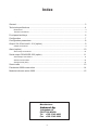
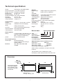
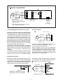
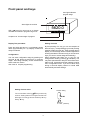
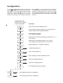
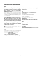
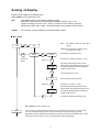
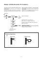
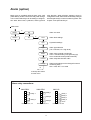
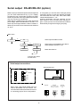
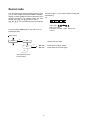
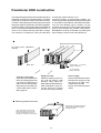
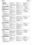
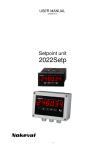
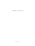
Nokeval
No 270503
User's Manual
Model 2041
for strain gauge
sensors
1
Index
General ............................................................................................................................ 3
Technical specifications ................................................................................................... 4
Dimensions ....................................................................................................................................... 4
Terminal connections ........................................................................................................................ 5
Front panel and keys ........................................................................................................ 6
Configuration ................................................................................................................... 7
Configuration parameters ................................................................................................. 8
Output 0/4-20 mA and 0..10 V (option) ............................................................................. 9
Output connections ........................................................................................................................... 9
Alarm (option) ................................................................................................................ 10
Alarm relay connections .................................................................................................................. 10
Serial output RS-485/RS-232 (option) .......................................................................... 11
Serial output connections ................................................................................................................. 11
Serial communication ...................................................................................................................... 12
Serial protocol (SCL) ....................................................................................................................... 12
Secret code ................................................................................................................... 13
Panelmeter 2000 construction ........................................................................................ 14
Modular indicator series 2000 ........................................................................................ 15
Manufacturer:
Nokeval Oy
Yrittajakatu 12
FIN-37100 NOKIA
Tel. +358 3 342 4800
Fax. +358 3 342 2066
2
2041 Panelmeter for strain gauge sensors
•
•
•
•
•
•
•
•
•
•
Strain gauge sensors with 4- or 6 -wire connection
Excitation voltage 10V to sensors, max 150 mA
6-digit processor-based LED-display
Settings via front panel keys
Output 0/4..20 mA, 0..10 V
Serial output RS-232 or RS-485
2 - 4 alarm relays
Display taring via front panel key
Measuring accuracy < 0,05 % of span
Power supply 85..240 VAC or 12..32 VDC/ 24 VAC
galvanically isolated from input and output. Analog
conversion is done by a 16-bit AD-converter (resolution 1/
64000) and the number of measurements is 3 per second.
Separate passwords can be set for access to the
configuration menu and alarms. The display can be damped
with a digital filter if necessary. The number of decimals on
the display is selectable. Front panel protection rating is
IP65.
The versatile panelmeter 2041 is designed for strain gauge
sensors. Strain gauge sensors can be connected with 4 or 6
wires. The 6-wire connection removes the lead wire resistance,
as bridge voltage is measured from the sensor poles, and
therefore it is recommended for applications requiring very
high accuracy. The panelmeter provides 10 V excitation voltage
for sensors, max. four 350 ohm sensors. Options to the 2041
include output 0/4-20 mA , 0-10V, 2..4 alarms or serial output
RS-485/232.
The panelmeter series 2000 is very flexible and easy to
modify by changing input cards for different kinds of sensors,
such as temperature sensors, pulse sensors, serial inputs
etc. The modification does not require any calibration. The
optional cards are the same for all the instruments in this
product family. Each panelmeter type has its own datasheet.
Display scaling and taring is easy via front panel keys. Scaling
can be carried out in two different ways, either by applying the
mV values of the bridge or using the teaching function. The
teaching is done by first loading the sensors with the min.
weight and then with the max. weight, after which the meter
w
i
l
l
automatically count the scaling.
Separate field enclosures can be supplied for 1 to 3
panelmeters.The 2041 is also available in the field display
series, model 2800-2041.
In applications where the sensor loading is not in balance a
separate serial connection unit of the sensors 20 SA-4 can
be used to prevent the nonlinearity caused by the imbalance.
There are two power supply alternatives: one for line voltage
85..240 VAC and the other 12..32 VDC/ 24 VAC, both
Modular panelmeter 2041
Options (B-C):
6-digit bright red
LED panel meter
Option cards, slots B or C
Alarm relays (B or C)
Configuration and
display scaling via
front panel keys
60.000
Serial communication(B or C)
E²
E²
Output (B)
DAC
+10 V
Alarms:
2 to 4 relays
Outputs:
0/4..20 mA, 0..10 V
RS-232 or RS-485
I = max. 150 mA
Input card A:
- microprocessor
- bus control
- panel key reading
- display control
- output and alarms
16 bit
+ Sense
ADC
mV-output
- Sense
1-4 sensors
Power supply:
85..240VAC or
12..32 VDC / 24 VAC
The panel meter can easily be
modified to accept other sensors by
only changing the input card A
Input card 2041
3
Technical specifcation:
Sensor
Sensor connection
Bridge connection
Bridge supply
Measuring range
Sensitivity settings
Accuracy
Repeatability
Temperature drift
strain gauge, max 350W parallel
4- or 6 -wire connection
full bridge or half bridge
10 VDC, max. 150 mA
25..50 mV
mV/V, freely selectable
<0,05 % FS
<0,02 % of span
0,0028 % /°C
Output (option):
Outputs
Output range
range,
0..20 mA, 4..20 mA and 0..10 VDC
scaleable on the whole display
scaling via front panel
Accuracy
0,05% of the scaled display range
Galvanic isolation test voltage 2000 VDC
Load resistance
maximum 700W
General:
Display range
6 digits, bright red (or green) LED ,
digit
height 14,5 mm, brightness
selectable
Display scaling
on the whole range via front panel
Display taring
via front panel keys
Teaching function applying min/max weights
Configuration
via front panel keys
Case
96 x 48 x 110 mm
Front panel protection IP65, with a rubber gasket
Operating temp.
0..60 °C
Terminals
detachable, max. 1,5 mm²
Power supply
85..240 VAC or 12..32 VDC /
24VAC
Weight
240 g
How to order:
Alarms (option):
Relays
2..4 alarm relays, max 230 VAC / 2A
Optional cards 2000-REL2 or 2000REL3, 4 relays (2x 2000-REL2)
prevent
the use of other options
Serial output (option):
Serial output
RS-232 and RS-485
Only for measurement reading or
setting of alarms
Baud rate
300, 1200, 2400, 4800, 9600
or 19200
2041-OUT- REL2-24VDC
Type
Output OUT
Alarm card REL2
Power supply:
85..240VAC or
12..32 VDC/24VAC
Optional cards (2 options available at a time):
Output card
2000-OUT
Alarm card, 2 relays
2000-REL2
Alarm card, 3 relays
2000-REL3
Serial output, RS-232/485 2000-RS
(When ordering a panelmeter, the “2000” of the cards
is left out.)
The panelmeter ia also available with a green
LED display: please specify 2041GR in the order code.
Dimensions
ø2,0
105
48
Case corners have pins
which help installation.
Pins centralizes meter
into panel cut out made
with DIN-tool.
96
6
Panel cut out
43.5 (K) x 90.5 (L) mm
4
10
Gasket (IP65)
Terminal connections:
2041
+10V exitation
+ sense
+ input
- sense
0V
- input
A
B
6
5
4
3
2
1
6
5
4
3
2
1
C
+ 0-10V
Common
+ 4-20 mA
6
5
4
3
2
1
7 8 9
Card slot B for
optional card:
analog output
Bridge sensor
Max 4 x 350 ohm (150 mA)
Exitation voltage from terminals 6
(10V) and 1 (0V)
Power
85..240 VAC
or
12..32 VDC
3 (+) and 1 (-)
Sensor cable protective sheath is connected
only in one point into terminal 1.
Connecting bridge sensor with 4- or 6- wires:
4-wire connection
Bridge sensors exitation voltage is measured directly
from sensor poles. Processor corrects display value
if voltage differs from 10 Volts. Selected 6-wire connection technique enables also use of separate voltage supply which voltage may vary between 7..13 V.
Unit accepts also 4-wire connection but then the
sense wires must be connected to voltage supply
terminals (short cut 5-6 and 1-2). This 4-wire connection can be used if the accuracy demand is unimportant or if the sensor lead wire error is corrected by
rescaling the display with known error.
If the sensror is not connected with 6-wires the lead
wire resistance will reduce the exitation voltage and
display shows too low values. How big this error is
depends on the current level in wires and on line
resistance.
An example: If the line resistance on each sensor is
2 ohms it means that four 350 ohm bridges in parallel
causes 87,5 ohm load to 10 V exitation voltage.
Sense-wire connection
A
+10V exitation
6
5
4
3
2
1
+ input
0V
- input
Bridge sensor
Sensor current can be calculated as: 10V/87,5 ohm
=114,2 mA. Voltage in bridge poles is then:
10V-(114,2 mA x 2 ohm)=9,776V.
Sensor message is 2,24 % too low compared to
10.000V exitation voltage. Bridge exitation voltage is
directly comparable to received mV-input and vice
versa. Model 2041 has continuous exitation voltage
measurement function and therefore voltage don't
have to be exact in bridge poles.
Half bridge connection:
Model 2041 accepts also half bridge sensor. This is
an optional function which must be specified when
ordering the unit. Unit which is ordered for half bridge
sensor can be used with full bridge connection by
replacing the short cut jumber as drawn below.
Half bridge connection in below picture. Terminal 3 is
not connected. Sensor cable protective sheath is
connected only in one point into terminal 1.
2041
+10V exitation
+ sense
Riviliitin
+ input
- sense
0V
Half bridge = Short cut connected
Full bridge = No short cut (default)
Half bridge connection
5
6
5
4
3
2
1
Front panel and keys
Conf-light indicates
program stage
Alarm lights A1 and A2
5620.0
With ▲▼-keys You can move on or change
numbers and values in programming menu.
*
Accptance of chosen stage of program
Display Tare procedure:
Setting of alarms
Press and hold right arrow (>) until display shows
0000 (approximately for 3 s). Display is tared and
ready to measure.
By first pressing of ➤ key you can see setpoint of
alarm one (A1), correspondingly by second pressing
setpoint of alarm two (A2) etc. Third pressing returns
display to normal stage. Alarm indication light blinks
showing that alarm has been set (if you do not touch
keys you come to normal stage automatically).
When indication light blinks (A1 or A2) you can
change alarm value by pressing ▲ and ▼ key. You
may have optional alarm relays for each alarm level.
Alarm mode, hysteresis and other settings must be
set in configuration menu. If you do not touch keys
during 8 seconds display returns to normal state
automatically and save settings.
Configuration
You can enter configuration stage by pressing two
seconds ▲ and ★-keys at same time. In program
stage f. ex. scaling of display, sensor selection and
alarm mode are chosen.
See closer in chapter programming.
Setting of alarm value
Number setting
You can set alarm value by ▲▼-keys number by
number. Setting starts from largest number from
left to right. You may go to next number by ➤ -key.
Exit by ★-key.
400.00
Numbers
0...9 and , (decimal)
6
Configuration
level with ★ key. You may set alarms in configuration
or in display stage. Alarm levels can be set in configuration state or measuring state. You can cancel changes
by selecting text UnDo to display and by pressing ➤
key. Next page describes in more details configuration
functions.
You can enter configuration state by pressing two
seconds ▲ and ★ keys at same time. By arrow keys
▲ and ▼ you can move upwards and downwards in
main menu. By pressing ➤ key you can enter
configuration state at wished point. From setting
state you can skip direct to save state or to previous
Configuration start:
Press two second ▲ and
★ keys at same time
Description
Sens
Select sensor selectivity Default 2mV/V
Load
Select display value with 6 digits for max. load of sensors,
number of decimals are selected separately
Dec
Select number of decimals
0 = no decimals in display
Filter
Digital filter for input signal (damping) selectable 0.01...1.0
(1.0= no filter)
Halt
Display shows zero below Halt value, e.g. on range
0..5.0 display should be showed zero, set Halt = 5.0
Bri
Display brightness 1..15=brightest, Default 7
Output
Alarm 1
Alarm 2
Serial
Code
Cal
➤
➤
➤
➤
➤
Output settings (page 10)
Alarm 1 settings (page 11)
Alarm 2 settings (4 relays selectable in menu)
Serial output settings (page 12)
Secret code settings (page 14)
Unit calilbration state (factory setting)
★
Save
Undo
➤
Save settings and exit from configuration.
➤
Undo changes and exit from configuration.
7
Configuration parameters
Sense
Typical sensor sensivity is 2 mV/V which you will find
in label of sensors. Change SET value according to
sensivity of sensors. Changing this value will have
reserved effect on display. For example changing
default selecetivity 2 mV/V to 2,2 mV/V, display
reading will reduce 10%.
Measuring range is defined from selectivity as follows
Sensor selectivity 2 mV/V is multiplied with the bridge
voltage. If selectivity is 2 mV/V and the bridge voltage
is 10 V the input measuring range will be 20 mV (2 mV/
V x 10V =20 mV).
Load: Set or Teach
You can make scaling by two different ways as follows:
SET selection indicates the weighing value which
gives the maximum signal from the bridge. Unit uses
this value to calculate the maximum mV-signal with
maximum load on sensor. If display value is e.g. 5%
too low you can fix the display by increasing the Load
value 5%.
Teach selection gives possibility to use reference
loads for scaling, see page 9.
Dec
Number of decimals in display. Select 0…5 with stkeys and accept with H-key.
Filter
Display filtering. Filtering damps restless display by
large number values. Measuring interval is 0,4 s.
Value setting between 1(min) ..0.010 (max).
1.000 = no filter
0.200 = normal filtering
e.g. 0,2 =(1/5) one new value + 4 old values
or 0,1=(1/10) one new + 9 old values (very steady)
8
Halt
Display can be set to show zero below Halt value e.g.
the display should be showed zero when weighing
value is under 10, set halt value 10. You can use also
negative values.
Bri
Display brightness 1..15 = brightest. Default 7.
Output (option)
Output settings. See chapter "Output"
Alarm 1 and 2 (option)
Alarm settings. See chapter "Alarm"
Serial (option)
Serial output settings. See chapter "Serial output"
Code
Secret code settings. See chapter "Secret code"
Cal
For factory settings
Undo, Save
Exit from configuration stage without saving changes
(Undo) or save and exit (Save).
Scaling of display
Display can be scaled on two different ways.
Select LOAD in menu and press ➤-key.
SET:
Enter display value on max.loading signal from bridge.
Example: If sensor gives 2 mV/V and supply voltage for sensor is 10 V, max
signal from bridge is 2 mV/V x 10V = 20 mV. If you like to show 5000 for max input
signal (20mV), SET value = 5000. The display range is now 0-5000 on input 0-20 mV.
TEACH:
You can teach scaling of display by using two reference loads.
Main menu
X
Load
Set
Set
Set display value on max input
signal
Teach You can teach display using
two reference loads.
Teach
Æ
Return by
★-key
X
Load 1
X
(Mittaus Lo)
10.0000
Æ
Set minimum reference load
Accept min. load by pressing ➤-key
Set value respecting minimum load
with 6 digits. Showed decimals are only
for setting. (Display desimal setting is
made in main menu)
Accept setting by ★-key
Load 2
Set maximum reference load
X
Accept min. load by ➤-key
(Mittaus Hi)
1000.00
Set value respecting maximum load
with 6 digits. Showed decimals are only
for setting. (Display desimal setting is
made in main menu)
Accept teaching by pressing ★-key
Æ
Zero shifting (factory setting = 0)
Zero
This function is recomended only when taring or teaching functions can not be made.
You can shift the display to zero or other values by using zero shifting. Typical
application is level measurement based on buoyancy in whrere max level of tank = zero
load and min level of tank = max. load (opposite to normal weighing).
9
Output 0/4-20 mA and 0..10 V (option)
The display may be provided with isolated output,
ranges 0..20 mA, 4..20 mA or 0..10 V, which are
programmable.
You can mount output card to slot B or C (default B).
Calibration information is saved to card and no cali-
bration is needed in configuration. You need not select
card in programming because meter recognizes the
mounted card.
Programming: select Output selection in main menu
and press ➤ key. See below description.
Main menu
Output
➤
➤
Type
OFF
0-20 mA
4-20 mA
0-10 V
Output type selection
Zero
Set display value on min output 0 V,
0mA or 4mA. e.g. display 0.0 kg=4 mA
Span
Set display value on max output 10 V or 20mA, e.g.
2000.0 kg = 20 mA
➤
Cal
Current
Voltage
★
Output signal calibration.
Output card is calibrated in the factory and only
scaling of output is needed.
★-accept and return
to main menu
Output connections
Output 0-10V
6
5
4
3
2
1
Output 4-20 mA
(+)
(-)
6
5
4
3
2
1
0-10V
Slot B
(-)
(+)
Slot B
10
0-20 mA
4-20 mA
Alarm (option)
Meter may be provided optional alarm relay card
(2000-REL2). In REL2 card is two relays with change
over contact. Both relays can be setting in configuration state: alarm level, hysteresis, alarm type and
relay direction. When all alarm settings is done in
configuration mode, alarm levels can be easily changed
with frontpanel keys in normal measuring state. See
chapter "Front panel and keys".
Main menu
Alarm 1
➤
Alarm not used
Off
Alarm 2
➤
On
Level
Alarm level settings
Hyst
Hysteresis settings
Type
Alarm type selection
(LO = low level; HI = High level)
Reset
Alarm reset, manual or automatic
User = manual reset by front panel key (★)
Auto = automatic reset (On/Off controller)
Contact
Alarm relay direction NO or NC
Alarm level settings can be changed in normal
measuring state
ON = used, OFF = not used
Change
★
★-accept and return
to main menu
Alarm relay connections:
2000-REL2
6
5
4
3
2
1
2000-REL3
Relay 1
Relay 2
max. 260 VAC, 2 A
6
5
4
3
2
1
2000-I/O
Relay 1
Relay 2
Relay 3
max. 260 VAC, 2 A
11
6
5
4
3
2
1
Relay 1
Relay 2
Relay 3
Relay 4
Com
max. 60 V, 100 mA
Serial output RS-485/RS-232 (option)
Meter may be provided with optional serial output and
you can read measurements by e.g. PC. Display
programming can not be made via serial port. Additional card provides serial signal RS232 and RS485,
only one of those can be selected.
Serial signal is isolated from both input signal and
power supply. Meters with RS485 can be max. 31 in
same loop and longest distance 1000m. RS232 enables only connection of one meter and max. distance
10..20 m.
In config state you can first select card type (serial)
mounted to slot B or C and then address and Baud
rate. baud rates are: 300, 1200, 2400, 4800, 9600,
19200 and addresses 0...127.
Program remembers card type mounted, if it has
been saved by save command when leaving program. In case you can not choose serial card, slot has
automatically recognized card (plug and play).
Main menu
➤
Serial
Serial output RS485 not used
Off
➤
Slot B
Slot C
Address
Serial output card installed to the Slot B.
Serial address selection 0..127
Baudrate
Baud rate selection
★
★-accept and return
to main menu
Serial output connections:
Serial output card
Slot A
6
5
4
3
2
1
A
B
RS-485
Term
Fs
6
5
4
3
2
1
2000-RS
Serial output
on off
Input
TxD
Com
RxD
Term = terminated resistor, Fs = Fail safe
Slot B or C
R S232
R S485
Last unit on
bus
off
off
off
Term
Fs
Term
Fs
Term
Fs
12
on
on
on
When using serial signal RS485 last unit
must be terminated 110 ohm resistor. You
can make termination at terminal connectors
or connecting jumper Term to ON position.
R S485
other units on bus
(Factory settings)
Termination 110 ohm
on last units
Address 2
5620.0
*
Address 1
5620.0
Address 0
Data acquisition
with PC
5620.0
*
*
RS485
Twisted pair cable
Serial communication
e.g.
One wants the measurement result from the display
unit address 1. An inquiry is sent:
MEA CH 1 ? (ASCII codes shown for <BCC>
calculation)
Baud rate: 300, 1200, 2400, 4800, 9600 and 19 200
1 Start, 8 Data and 1 Stop bit, no parity.
Serial protocol (SCL)
MESSAGES: When asking the measurement data
from the panelmeter 2041 through the serial port, a
command sequence which is in accordance with the
SCL protocol is used for the inquiry.
M E A
C H
1
?<ETX> <BCC>
4Dx45x41x20x43x48x20x31x20x3F x03
= 6F
(XOR operation is presended with a character x)
(ASCII code 20h corresponds to space character)
<ADDR+80h>COMMAND STRING<ETX><BCC>
So the following bytes are sent to 2041:
81 4D 45 41 20 43 48 20 31 20 3F 03 6F
<ADDR>
The first byte character to be sent contains the address of the destination device and at the same time
functions as the start indicator of the command. The
uppermost bit of this byte is set, in other words 80H
(128 in decimal) is added to the address.
RETURN MESSAGE: The answer from the
panelmeter 2041 is obtained in the following format:
<ACK>RETURN MESSAGE<ETX><BCC>
COMMAND STRING: When measurement data is
requested, the actual command is: MEA CH 1 ? , in
which 1 means the channel number. (there is only one
channel in the panelmeter 2041 so the number is
always 1).
<ACK>
The first byte of the answer contains the start of the
answer <ACK> (ASCII-code 06h) and the answer
itself, endmark <ETX> (ASCII- 03h) and the checksum
of the answer which is calculated from all the byte
characters of the answer including <ACK> and <ETX>.
2041 counts the checksum in which case the receiver
does not need necessarily to care about it.
e.g.
e.g. When a measurement result is for example 21.3,
it will be obtained from the panelmeter in the following
form
<ACK> 2
1 .
3 <ETX> <BCC>
Answer: 06 32 31 2E 33 03
1B
<ETX>
<ETX> mean the end mark of the command,
ASCII character 03h.
<BCC>
Finally the checksum is calculated using XOR operation on the byte characters of the actual command
including the ETX, excluding ADDR byte. In the
example the ASCII codes have been presented in
hexadecimal.
13
Secret code
You can enter secret code by pressing six time keys
(1-4) in wished order (lines goes forward in display).
Setting must be repeated in same order before new
setting is accepted. For example: Press one after
another keys ▲ ▲ ★➤▲ ▲ and once more
▲ ▲ ★➤▲ ▲. You may think the keys as numbers
from left to right 1,2 3,4 in order to help recording and
remembering.
e.g.
★
1
2
3
4
▲▲
Input code ▲ ▲ ★➤
★➤▲
and once more.
Example number value would be
113411.
In menu position Code press ➤ key and move on
to selection state.
Main menu
Code
➤
Off
On
Secret code not used
➤
Ent. Co
Ent. Co
★
★-accept and return
to main menu
14
Enter secret code (6 marks)
Enter same secret code again
Panelmeter 2000 construction
second relay card into slot B. If you
accept only closing or opening relay contacts, you
need only one relay card with 4 relays placed into slot
C. The slot B is now usable for other optional outputs.
You can have different types of meters by only
changing the input card in slot A. Data sheet of each
type of meter dictates the possible combinations.
Recalibration of card is not needed; only scaling and
other settings must be set by front panel keys.
The 2000 series panelmeters are modular and easy to
assemble. According to customers wishes. The basic
construction consists of mother board with tree slots,
A, B and C. Slot A determines meter type and provides
always input signal. Slot B and C are interchangeable.
As factory delivery input signal is always installed into
slot A , mA output into slot B and alarms into slot C. In
case of f.ex 4 alarms and relay card with 2 changeover contact (2 + 2 relays) are used, you must place
All cards have calibration
memory
Slots A-C
A
B
C
Power supply 12..32 VDC
(Green connector)
or 85..240 VAC
(Grey connector)
Change of meter type:
Input card is placed always to
slot A. By changing input card
you can get an other type of
meter. You can change meter
with pulse input to meter with
current input, thermocouple,
strain gage etc.
Additional slots:
Additional cards provide output 4..20 mA, alarms, serial
interface, BCD output etc.
Meter data sheet dictates possible combinations. grey connectors allow line voltage
85..230 VAC (relay contacts).
Power supply:
There are two different mother
boards power supply 85..230
VAC and 12..32 VDC. VDCmother board accepts
24 VAC. Connectors are colour
coded.
Removing meter from case:
Press gently case behind front panel
and draw frame outwards gripping
upper part of frame.
Loose connectors and front panel,
draw meter out from front. You may
remove mother board from rear by
opening four screws in corners of case.
15
Nokeval Oy
Yrittajakatu 12
37100 NOKIA, FINLAND
email [email protected]
Tel. +358 3 342 4800
http:// www.nokeval.com
Fax.+358 3 342 2066
16