1
User Manual
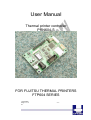
Thermal printer controller
PRN604-S
FOR FUJITSU THERMAL PRINTERS
FTP604 SERIES
12-02-2003
Page 1-1 of
51
- 1-1 -
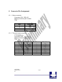
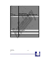
VERSION HISTORY
Version
0.9
0.91
0.92
0.93
Date
020712
021022
030111
030125
Init
BB
BB
BB
BB
Status
Draft
Pre-release
Pre-release
Pre-release
Description
First release
Second pre-release
Third pre-release
Connector updated
Copyright 1999-2003 by I/F-COM A/S.
All rights reserved.
I/F-COM A/S has prepared this manual for use by I/F-COM A/S’
customers.
The information contained herein is the property of I/F-COM A/S and
shall not be reproduced in whole or in part without the prior written
approval of I/F-COM A/S.
I/F-COM A/S reserves the right to make changes without notice to the
specifications and materials contained herein and shall not be
responsible for any damages (including consequential) caused by
reliance on the materials presented, including but not limited to
typographical, arithmetic, or listing errors.
Fujitsu is a trademark of Fujitsu Electronics LTD.
Windows is a trademark of Microsoft Inc.
Safety Precautions
•
•
•
Please read and understand these specifications thoroughly before
using the printer. Please keep the specifications carefully in a place
where they may be easily consulted when the printer is used.
Please do not modify or service this printer as this may cause
unpredictable faults to occur.
The product is not intended to be installed in devices such as those
used in life-support medical equipment, undersea relays, and
aerospace applications or for nuclear power control, in which
12-02-2003
Page 1-2 of
51
- 1-2 -
•
extremely high reliability is required. If you are considering such
applications, please consult our customer service department.
There is a general possibility of component failure. Every effort has
been made to improve product quality but such failures cannot be
completely excluded. Please assume that such failure may occur
before using this printer.
We would urge that these specifications should be thoroughly understood and the
printer used safely in your company or associated organisation. Please indicate or
describe in your products and in the user manuals those items, which are related
to the prevention or avoidance of danger and draw these to the attention of the
eventual client (the user).
12-02-2003
Page 1-3 of
51
- 1-3 -
1
SYSTEM DESCRIPTION ............................................................................................1-7
2
INSTALLATION ...........................................................................................................2-7
2.1
UNPACKING ..............................................................................................................2-7
2.2
LABELS .....................................................................................................................2-7
2.3
INSTALLATION ..........................................................................................................2-8
2.4
POWER SUPPLY .........................................................................................................2-8
2.5
SETTINGS ..................................................................................................................2-9
2.6
SERIAL INPUT/OUTPUT ...........................................................................................2-12
2.6.1
Serial data transfer ........................................................................................2-12
2.6.1.1
Serial input/output port................................................................................2-13
2.6.2
Setting functions.............................................................................................2-13
2.7
THERMAL HEAD CONTROL ............................................................................2-14
2.7.1
Thermal Head Drive Operation .....................................................................2-14
2.7.2
Peak power limitation ....................................................................................2-14
2.7.3
Head Control Circuit .....................................................................................2-15
2.7.4
Head temperature measurement circuit .........................................................2-15
2.7.5
Vhead interrupt circuit...................................................................................2-15
SPECIFICATIONS..............................................................................................................2-16
3
FUNCTION ..................................................................................................................3-17
3.1
GENERAL ................................................................................................................3-17
3.2
SERIAL COMMUNICATION. ......................................................................................3-17
3.3
USB COMMUNICATION. ..........................................................................................3-17
3.4
IRDA COMMUNICATION. ........................................................................................3-17
3.5
FIRMWARE UPGRADE. .............................................................................................3-18
3.6
AUTO FORM FEED....................................................................................................3-18
3.7
CHARACTER DESIGN ...............................................................................................3-19
3.7.1
Normal Character. .........................................................................................3-19
3.7.2
Low Character ...............................................................................................3-19
3.7.3
Underline .......................................................................................................3-20
3.7.4
Bold ................................................................................................................3-20
3.7.5
Reverse ...........................................................................................................3-20
3.7.6
Italic. ..............................................................................................................3-20
3.7.7
Font sizes. ......................................................................................................3-20
3.8
I/F-COM SIMPLE COMMAND SET. ...........................................................................3-21
3.8.1
Small Font......................................................................................................3-21
3.8.2
Low Font ........................................................................................................3-21
3.8.3
Narrow Font...................................................................................................3-21
3.8.4
Normal Font...................................................................................................3-21
3.8.5
Wide Font.......................................................................................................3-21
3.8.6
High Font .......................................................................................................3-22
3.8.7
Large Font......................................................................................................3-22
3.8.8
Xlarge Font ....................................................................................................3-22
3.8.9
Line Feed .......................................................................................................3-22
3.8.10 Barcode on .....................................................................................................3-22
3.8.11 Feed Forward ................................................................................................3-23
3.8.12 Reverse off......................................................................................................3-23
3.8.13 [Name] Reverse off .......................................................................................3-23
3.8.14 Reverse on ......................................................................................................3-23
12-02-2003
Page 1-4 of
51
- 1-4 -
3.8.15
3.8.16
3.8.17
3.8.18
3.8.19
3.8.20
3.8.21
3.8.22
3.8.23
3.8.24
3.8.25
3.8.26
3.8.27
3.8.28
3.8.29
3.8.30
3.8.31
3.8.32
3.8.33
3.8.34
3.8.35
3.8.36
3.8.37
3.8.38
3.8.39
3.8.40
3.8.41
3.8.42
4
MAINTENANCE.........................................................................................................4-32
4.1
4.2
5
DAILY USE ..............................................................................................................4-32
STORE/TRANSPORT .................................................................................................4-32
SPECIFICATIONS......................................................................................................5-33
5.1
5.2
5.3
5.4
5.5
6
Underline off ..................................................................................................3-23
Underline on ..................................................................................................3-24
Bold off...........................................................................................................3-24
Bold on ...........................................................................................................3-24
Italic off..........................................................................................................3-24
Italic on ..........................................................................................................3-24
Initialise Printer .............................................................................................3-25
Request Software version ...............................................................................3-25
Request Status ................................................................................................3-25
Request Analog voltage..................................................................................3-25
Request Temperature .....................................................................................3-26
Sub command set............................................................................................3-26
Upgrade command.........................................................................................3-26
Set auxiliary output ........................................................................................3-26
Automatic sending status................................................................................3-27
Stop sending automatic status........................................................................3-27
Color/Grey scale graphic...............................................................................3-27
Enable saving data.........................................................................................3-27
Save data to board .........................................................................................3-28
Change dot size ..............................................................................................3-28
Change form feed length ................................................................................3-28
Change baud rate...........................................................................................3-28
Change form feed time ...................................................................................3-29
Feed Paper.....................................................................................................3-29
Compensate Burn time ...................................................................................3-29
Graphic data – non compressed.....................................................................3-30
Graphic data – compressed ...........................................................................3-30
Escape sequences, overview...........................................................................3-30
ELECTRICAL DATA .................................................................................................5-33
MECHANICAL DATA ...............................................................................................5-33
ENVIRONMENTAL DATA .........................................................................................5-33
EMC & ESC ..........................................................................................................5-33
TEMPERATURE TEST ...............................................................................................5-34
CONNECTOR PIN ASSIGNMENT ..........................................................................6-35
6.1.1
Motor connector.............................................................................................6-35
6.1.2
Thermal Head connector................................................................................6-35
6.1.3
Thermal Head connector................................................................................6-36
6.1.4
Thermal Head connector................................................................................6-36
6.1.5
IRDA connector..............................................................................................6-37
6.1.6
AUX INPUT connector ..................................................................................6-37
6.1.7
Power connector ............................................................................................6-38
6.1.8
USB connector ...............................................................................................6-38
6.1.9
AUX connector...............................................................................................6-38
6.1.10 Serial connector .............................................................................................6-39
6.2
MECHANICAL DRAWINGS .......................................................................................6-40
7
APPENDIX...................................................................................................................7-41
12-02-2003
Page 1-5 of
51
- 1-5 -
7.1
SEIKO COMPATIBLE COMMAND SET (OPTIONAL) .....................................................7-41
7.1.1
Escape sequences, overview...........................................................................7-41
7.2
FUJITSU COMPATIBLE COMMAND SET (OPTIONAL) ..................................................7-42
7.2.1
Escape sequences, overview...........................................................................7-42
7.3
APS COMPATIBLE COMMAND SET (OPTIONAL) .......................................................7-45
7.3.1
Escape sequences, overview...........................................................................7-45
7.4
ESC/POS COMPATIBLE COMMAND SET (OPTIONAL) ...............................................7-47
7.4.1
Escape sequences, overview...........................................................................7-47
7.5
OPTIONAL SENSOR DESCRIPTION.............................................................................7-49
12-02-2003
Page 1-6 of
51
- 1-6 -
1 SYSTEM DESCRIPTION
This reference manual describes the specifications, functions, and
operating procedures for the PRN604-SInterface Board.
The PRN604-S is an interface board for the FTP604 series printer
mechanisms.
This reference manual also describes the print operation of the
FTP604. Read this reference manual thoroughly before using the
PRN604-S. PRN604-S is designed for the following Fujitsu printers:
FTP-624MCLxxx
FTP-634MCLxxx
FTP-644MCLxxx
PRN604-S consists of an interface board.
The communication is RS232, USB or IRDA.
PRN604-S can print graphic data either compressed or noncompressed.
Burn time can be set to control the printing intensity
Windows 95/98, 2000, NT and CE drivers are available at
http://www.if-com.com, for easy operation by PC. Linux drivers are
available upon request.
2 INSTALLATION
2.1
Unpacking
Remove the cover observing precautions for Electro Static Discharge
(ESD). Make sure that board is handled with care with respect to
Electrostatic environment.
2.2
Labels
PRN604-S has 3 labels;
Label 1 on backside ex. Ifxxxxxx is a unique ID number. For service
and question based upon 1 particular board please refer to this number.
Label 2 on topside ex. PRN604-S is part number. Please refer to this
number upon reordering. Make sure that software revision is applied at
same time.
Label 3 is an internal code. Please ignore.
12-02-2003
Page 2-7 of
51
- 2-7 -
2.3
Installation
PRN604-Sis fastened in the product by 4 M3.3 screws. The cables (for
the thermal head, the stepper-motor and detector) are placed in the
thermal printer connector on the PCB. 1 Mounting hole is grounded.
See drawing for more details.
(a) To connect or remove the connector, always turn off the power in
advance. If the connector is connected or removed while the
power to the printer is on, errors may occur.
(b) The connector of each cable must be correctly locked and
connected. The connector at the head side has no lock feature.
Check that the connector at the head side is completely inserted.
(c) To install the interface, carefully check each cable so that
excessive force is not applied to each cable. Especially, carefully
check the head connection cable because it affects the head
pressure force. If the print head connector is not completely
connected, overheating or burning may occur in the print head.
2.4
Power supply
Single power supplies for the PRN604-Scontroller board. Voltage range
is 6-8,5VDC. 4A minimum @ 7,2V. Make sure that voltages never
exceed 8,5VDC.
(a) The power supply unit that satisfies the specified specifications
must be used. If a power supply unit that does not satisfy the
specified specifications is used, normal operation is not assured
and errors may occur.
(b) To turn on or off the power, a protective circuit must be mounted
on the control board in advance. For safety, the following
voltage change conditions must be satisfied:
12-02-2003
Page 2-8 of
51
- 2-8 -
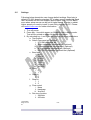
2.5
Settings
Following below description can change default settings. Baud rate is
default 115.200, however standard PC´s today cannot handle this Baud
rate. Windows OS does not support speed higher than 115.200 Baud,
even when setup menus can be set to higher speed. In order to obtain
higher speed you need to install 3rd part utility program on PC. Please
visit www.if-com.com for further information.
1. Turn off power
2. Press Key 1 low while power up. Board is now in setting mode.
Text will be printed on paper for further information
3. By activating key 1 and 2 you can change following parameters:
a. Test printout
b. Select Command set (optional)
i. I/F-COM command set
ii. Seiko compatible command set (Optional)
iii. Fujitsu compatible command set (Optional)
iv. APS compatible command set (Optional)
v. ESC/POS compatible command set (Optional)
c. Baud rate
i. 9600
ii. 19.200
iii. 38.400
iv. 57.600
v. 115.200
vi. 230.400
vii. 460.800
d. Parity
i. 0
ii. 1
e. Data bit
i. 7
ii. 8
f. Stop bit
i. 1
ii. 2
g. Flow control
i. None
ii. Hardware
iii. Xon/Xoff
h. Dot size of printer
i. 384 dots
ii. 432 dots
12-02-2003
Page 2-9 of
51
- 2-9 -
i.
j.
k.
l.
m.
n.
12-02-2003
Page 2-10 of
51
iii. 448 dots
iv. 512 dots
v. 576 dots
vi. 640 dots
vii. 832 dots
viii. 1152 dots
Key 1 function
1. Input key
2. LED output
3. Label detect
4. Black mark detection
5. Paper near end function
6. Paper jam function
a. Stop printer
b. Send data to host
Key 2 function
1. Input key
2. LED output
3. Label detect
4. Black mark detection
5. Paper near end function
6. Paper jam function
a. Stop printer
b. Send data to host
Paper select
i. Paper 1
ii. Paper 2
iii. Paper 3
iv. Paper 4
IRDA
i. Enabled
ii. Disabled
Auto form feed
i. 0 sec.
ii. 1 sec.
iii. 2 sec.
iv. 3 sec.
v. 4 sec.
vi. 5 sec.
Form feed length
i. 0 mm
ii. 1 mm
iii. 2 mm
iv. 5 mm
- 2-10 -
o.
p.
q.
r.
s.
t.
12-02-2003
Page 2-11 of
51
v. 10 mm
vi. 20 mm
vii. 30 mm
viii. 50 mm
Grey scale printing
i. On
ii. Off
Acceleration
i. Slow
ii. Medium
iii. Fast
iv. Disable
Printing speed
i. 25%
ii. 50%
iii. 75%
iv. 100%
v. Disable
Burn strobe dark
i. 1
ii. 2
iii. 3
iv. 4
v. 5
vi. 6
vii. 7
viii. 8
ix. 9
Burn strobe light
i. -1
ii. -2
iii. -3
iv. -4
v. -5
vi. -6
vii. -7
viii. -8
ix. -9
Output
i. Cash drawer output
1. Solenoid time 0,2 sec.
2. Solenoid time 0,5 sec.
3. Solenoid time 0,7 sec.
4. Solenoid time 1,0 sec.
5. Solenoid time 1,5 sec.
- 2-11 -
ii. Winding motor
Settings will be effective upon turn off and on.
2.6
Serial Input/Output
If BUSY control is selected:
When 236 bytes of data have been stored in the input buffer, the
SBUSY signal becomes high to request that the computer temporarily
stop sending data. When the amount of data stored in the input buffer
becomes 235 bytes or less, the SBUSY signal changes to low to
request that the host device continue data transfer. Up to 16 bytes of
input data are guaranteed after the SBUSY signal has become high.
When an error occurs, the SBUSY signal becomes high. Data input is
prohibited until the error is cancelled.
If Xon/Xoff control is selected:
When 188 bytes of data has been stored in the input buffer, Xoff (1316)
is output through the TxD terminal to request that the host device
temporarily stops sending data. When the amount of data stored in the
input buffer becomes 124 bytes or less, Xon (1116) is output to request
that the computer continues data transfer. Up to 64 bytes of the input
data are guaranteed after
Xoff has been output. When an error occurs, the Xoff signal is output to
prohibit the data input.
When the error is cancelled, Xon is output.
2.6.1 Serial data transfer
The PRN604-Stransfers various data other than the Xon and Xoff
codes which are output when controlling Xon and Xoff.
Regardless of whether the input mode is serial or parallel, the following
data is transferred through the TxD terminal.
(a) Error codes when a hardware error occurs at initialisation
(b) The data when executing the Vhead voltage response (DC2+‘v’)
(c) The data when the error status response is set (DC2+’e’) and an
error occurs
(d) The data when executing the execution response request (DC2+‘q’)
(e) The data when executing the remaining RAM capacity response
(DC2+‘r’)
(f) The data when executing the environmental temperature response
(DC2+‘t’)
At the selection of serial input, data (b) through (f) is transferred
according to the transfer conditions, which are set using the function
12-02-2003
Page 2-12 of
51
- 2-12 -
switches. However, the hardware error code (a) has the same
conditions as those for parallel input.
When transferring data, data control by SBUSY and Xon/Xoff is not
executed and the data is transferred with no conditions.
All of the transmission conditions of serial data transfer for sending
hardware error codes are fixed at the selection of parallel input as
follows:
2.6.1.1 Serial input/output port
Serial data output (TxD)
When Xon/Xoff control is selected, the Xon/Xoff signal is output.
Data is output according to the transmission conditions, which are
set by the function switches.
All response data is output.
Serial data input (RxD)
Data input port
Data is input from the host device according to the transmission
conditions, which are set using the function switches.
Serial busy (SBUSY)
Indicates whether or not the PRN604-S is ready to receive data.
When the SBUSY signal is low, data can be input.
When Xon/Xoff control is selected, SBUSY is always low.
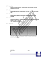
2.6.2 Setting functions
Error processing when receiving serial data
The PRN604-S receives and checks serial data according to the
transmission conditions.
When the PRN604-S has received one byte of data without errors, the
data is stored in the input buffer.
If there are any errors, the following data is stored in the input buffer
according to the type of error.
Error type Error code
Parity error (!: 2116)
Framing error (?: 3F16)
If the input data cannot be printed correctly and instead “!” or “?” is
printed, the transmission conditions between the host device and the
PRN604-S most likely does not match. If this happens, adjust the
conditions so that they match.
12-02-2003
Page 2-13 of
51
- 2-13 -
2.7
THERMAL HEAD CONTROL
Data Transfer to the Thermal Head
The PRN604-S transfers one dot line of data at 6 Mbps synchronized
with the CLOCK signal.
The data is transferred in order to the shift register inside the thermal
head from the left (when facing the paper feed direction).
The transferred data is then transferred by the head latch signal to the
latch register inside the thermal head. Turning on the head strobe
signal initiates printing of one dot line of data on the thermal paper.
2.7.1 Thermal Head Drive Operation
Generally, when the line thermal head is operating, the line is divided
into several blocks, which are activated one after another in succession.
For the line thermal head of the FTP604 printer mechanism, the line is
divided into 7 blocks called physical blocks, 216, 288 or 416 dots with
each. A strobe signal (/ST1 to /ST7) is allocated to each physical block
to activate it. To drive the head, physical blocks are activated in groups.
The group of physical blocks is called a logical block.
For the PRN604-S either dynamic division or fixed division can be
selected as the method of division for logical blocks. This selection is
made through a function. See settings for more information.
2.7.2 Peak power limitation
The PRN604-S counts the number of dots activated in each physical
block and groups the physical blocks into logical blocks to print a single
dot line so that the number does not exceed the specified maximum
number of activated dots. The PRN604-S determines logical blocks
each time it prints a single dot line.
In dynamic division, in order to avoid unclear printing, at the first step of
the motor the thermal head is driven and at the second step the paper
is fed.
Also, since the order of the printing blocks and printing speed are
changed in each dot line according to the content of the print data, print
quality may be lower than that in fixed division. If print quality is
regarded as important, printing in fixed division is recommended.
The maximum number of activated dots in the initialisation status is
specified using the function switches.
64 through 256 dots can, however, are set using the command for
setting the number of dynamic division dots.
12-02-2003
Page 2-14 of
51
- 2-14 -
When the maximum number of activated dots is 128 dots, and all of the
dots are driven, as shown in
2.7.3 Head Control Circuit
The PRN604-S has a function for measuring the resistance of the
thermal head connected to the FTP604.
The PRN604-S measures the resistance of the thermal head and
detects the errors at initialisation.
Based on the measurement, the PRN604-S determines how much
energy to apply. No adjustment is needed for replacing the FTP604 to
get the best printing.
2.7.4 Head temperature measurement circuit
The thermistor is mounted on the FTP604 to measure the temperature
of the thermal head.
The PRN604-S determines the energy to be applied to the head and
also checks for head temperature errors.
If the temperature of the thermal head is -10 °C or lower, or 80 °C or
higher, the PRN604-S stops driving and puts the printer in head
temperature error status. If the temperature of the thermal head is
returned to from -5 °C to 75 °C, the printer goes to printable status.
2.7.5 Vhead interrupt circuit
This circuit interrupts Vhead to prevent electrolytic corrosion of the
thermal head and to enable the detection of the resistance mentioned
above.
Electrolytic corrosion may significantly shorten the life of the thermal
head. Thermal paper ordinarily contains electrolytic material to prevent
sheets from sticking to each other due to static electricity. If there is too
much of this electrolytic material, high temperatures and humidity cause
the material to ionise, resulting in electrolytic corrosion of the thermal
head.
The PRN604-S turns the FET off and breaks the Vhead applied to the
thermal head during waiting status to prevent electrolysis corrosion of
the thermal head.
12-02-2003
Page 2-15 of
51
- 2-15 -
Specifications
Default settings
Interface
Serial RS232C, USB or IRDA
115.200 baud, 8 data bit, none parity, 1 stop bit, hardware
handshake.Baud rate can be changed by software.
Data format serial
USB Printer class specification.
Data format USB
http://www.usb.org/developers/data/devclass/usbprint11.pdf
IRDA (Ircomm specifications)
Data format IRDA
http://www.irda.org/standards/pubs/ircomm10.pdf
Command set
I/F-com
Transmission to host Requested status etc.
Printer supply
18V to 24V DC
Power on self test
Feed
Voltage compensation Burn time
Current consumption Operating 130mA, Printing up to XA @ 24V (TBD)
Printing speed
50mm/sec FTP624MCLxxx, 40mm/sec FTP634MCLxxx
Fontset
Western (Code 850, char 32-159)
Character size
8x14, 8x28, 16x14, 16x28, 16x56, 32x28, 32x56, 64x112
Character type
Normal, Bold, Underline, Italic, Reverse (white on black)
Default font
16x28
Paper detect
Digital
Graphics
Normal / Compressed
Auto load
80mm
Form feed
50mm
Line feed
LF
Maximum dimensions Width 77mm, Depth 50mm, Connected height 15mm
Mounting holes
Width 71mm, Depth 44mm, Diameter 3.3mm
Connectors
TBD
Weight
25g
Storage -40ºC to +85ºC 0-90 Operating 0C to +85ºC 10-90%RH
Temperature
Shock
100G XYZ
EMC
Emission: E-Field EN50081-1-1, Conducted EN50081-1-2
Immunity: E-field EN50082-1-1, Conducted EN50082-1-2, Over voltage EN50082-1-3
ESD Contact discharge 4kV, air discharge 8kV
Drivers
Windows 9x, Windows CE, Windows NT, Linux, Windows2000 and Windows XP
Approvals
CE, UL
Accessories
Serial Interface cable: CBL-002, 9pol SubD, female
Power cable: CBL-022
12-02-2003
Page 2-16 of
51
- 2-16 -
3 Function
3.1
General
Notice, when data is sent from the external equipment to the printer
controller, all data has to be sent as binary file. If data is being sent as a
character file, and some data in the file is equal to EOF, the rest will not
be received.
3.2
Serial communication.
Standard communication is;
Baud rate; 115.200 Baud
Data bits = 8
Stop bits = 1.
Parity = None
Flow control = Hardware handshake
Baud rate can be changed by changed by a software command.
3.3
USB communication.
Build in USB interface is 100% compliant to USB 1.1 and fully approved
by the USB organisation. For more details please contact I/F-COM.
By plug USB cable - Host system will recognise I/F-COM interface
board.
Before connecting USB cable please set USB port as offline. Interface
board will automatically online USB port. Data cannot be send from
interface board to host. USB is not a bi-directional communication.
3.4
IRDA communication.
PRN604-S is prepared for IRDA via connector for IRDA transmission.
Please contact I/F-COM for more information.
12-02-2003
Page 3-17 of
51
- 3-17 -
3.5
Firmware upgrade.
If firmware needs to be changed, alternative firmware can be
downloaded.
Please contact I/F-COM for firmware upgrade or changes.
The steps to download an alternative firmware in DOS are the following.
These steps only work for a serial connection, look further down how to
do it with USB.
1. Power the system off.
2. Disconnect printer.
3. Short circuit the pins “upgrade firmware”
4. Turn on printer
5. Write the following command “mode com1:9600,n,8,1”, this
command ensure that the serial port is at a known state.
6. Write the following command “xmode 1 +”, this command sets
the baud rate to 115.200, the xmode program can be
downloaded from the I/F-COM web site
http://www.if-com.com/data/drivers/xmode.zip
7. Run the following command, “copy “filename” /b com1”. The
filename represents the path and the filename of the new
firmware file. This file can be downloaded from website, or can
be emailed by I/F-COM.
I/F-COM also offers a Windows utility program in order to download
firmware through serial port. Visit www.if-com.com for more information.
For further information about downloading with the driver, can be
found in the driver installation guide.
3.6
Auto form feed
When paper no paper is present, it is possible to form feed new paper
automatic. While thermal head is down, place the paper at the roller.
After 2 seconds (default) the paper will be pulled in automatically.
Form feed wait time is 2 sec (default), but can be changed by a
command.
12-02-2003
Page 3-18 of
51
- 3-18 -
3.7
Character design
The following figures describes the design of different types of
characters (small):
3.7.1 Normal Character.
3.7.2 Low Character
12-02-2003
Page 3-19 of
51
- 3-19 -
3.7.3 Underline
When underline characters are printed the last line in the character
matrix will be marked.
3.7.4 Bold
When bold characters are printed the character is or with itself shifted
right.
3.7.5 Reverse
When reverse characters are printed the character matrix will be
negated.
3.7.6 Italic.
When Italic characters are printed every line will be shifted the following
number of dots to the right:
(Line number from bottom)/4
3.7.7 Font sizes.
Font
Small
Low
Narrow
Normal
Wide
High
Large
Xlarge
Width
Normal
Double
Normal
Double
Double
Quadruple
Quadruple
Octuple
Height
Normal
Normal
Double
Double
Quadruple
Double
Quadruple
Octuple
When the size is normal or greater a build in smooth function will
smooth the characters.
12-02-2003
Page 3-20 of
51
- 3-20 -
3.8
I/F-COM simple command set.
The following commands are use when communicating with the printer
controller. All other commands is ignored
3.8.1 Small Font
[Name]
[Format]
[Description]
3.8.2 Low Font
[Name]
[Format]
[Description]
3.8.3 Narrow Font
[Name]
[Format]
[Description]
3.8.4 Normal Font
[Name]
[Format]
[Description]
3.8.5 Wide Font
[Name]
[Format]
12-02-2003
Page 3-21 of
51
Small Font (8x12)
ASCII
NUL
Hex
00
Decimal
0
Chooses small font from the current print position.
Low Font (16x12)
ASCII
SOH
Hex
01
Decimal
1
Chooses low font from the current print position.
Narrow Font (8x28)
ASCII
STX
Hex
02
Decimal
2
Chooses narrow font from the current print position.
Normal Font (16x28)
ASCII
ETX
Hex
03
Decimal
3
Chooses normal font from the current print position.
This is the default font after power up or reset.
Wide Font (32x28)
ASCII
EOT
- 3-21 -
[Description]
3.8.6 High Font
[Name]
[Format]
[Description]
3.8.7 Large Font
[Name]
[Format]
[Description]
3.8.8 Xlarge Font
[Name]
[Format]
[Description]
3.8.9 Line Feed
[Name]
[Format]
[Description]
3.8.10 Barcode on
[Name]
[Format]
[Type]
12-02-2003
Page 3-22 of
51
Hex
04
Decimal
4
Chooses wide font from the current print position.
High Font (16x56)
ASCII
ENQ
Hex
05
Decimal
5
Chooses high font from the current print position.
Large Font (32x56)
ASCII
ACK
Hex
06
Decimal
6
Chooses large font from the current print position.
Xlarge Font (64x112)
ASCII
BEL
Hex
07
Decimal
7
Chooses Xlarge font from the current print position.
Line Feed
ASCII
LF
Hex
0A
Decimal
10
When the printer controller receives this byte the text
data in the buffer will be printed
Barcode on
ASCII
Hex
Decimal
Barcode 39
VT
0B
11
- 3-22 -
[Description]
Turns the barcode on until non-barcode character
received.
[Barcode char.] Space , $ , % , * , + , - , . , / , 0-9 , A-Z
[Notes]
The barcode 39 must start and end with the character
‘*’. This character is the start and stop character in
barcode 39, and the ‘*’ can only be used as start and
end character.
If the barcode length exceeds the paper size the last
barcode character will not be written as barcode. In that
case the barcode cannot be read because the last
character will not be ‘*’
3.8.11 Feed Forward
[Name]
[Format]
[Description]
Feed Forward
ASCII
FF
Hex
0C
Decimal
12
When this command is received the printer will print
whatever data it has in the buffer and feed forward
50mm
3.8.12 Reverse off
3.8.13 [Name]
Reverse off
[Format]
ASCII
SO
Hex
0E
Decimal
14
[Description] This command will switch off reverse printing
3.8.14 Reverse on
[Name]
[Format]
[Description]
3.8.15 Underline off
[Name]
[Format]
12-02-2003
Page 3-23 of
51
Reverse on
ASCII
SI
Hex
0F
Decimal
15
This command will switch on reverse printing
Underline off
ASCII
DLE
- 3-23 -
[Description]
3.8.16 Underline on
[Name]
[Format]
[Description]
3.8.17 Bold off
[Name]
[Format]
[Description]
3.8.18 Bold on
[Name]
[Format]
[Description]
Hex
10
Decimal
16
This command will switch off underline printing
Underline on
ASCII
DC1
Hex
11
Decimal
17
This command will switch on underline printing
Bold off
ASCII
DC2
Hex
12
Decimal
18
This command will switch off bold printing
Bold on
ASCII
DC3
Hex
13
Decimal
19
This command will switch on bold printing
3.8.19
Italic off
[Name]
Italic off
[Format]
ASCII
DC4
Hex
14
Decimal
20
[Description] This command will switch off italic printing
3.8.20 Italic on
[Name]
[Format]
[Description]
12-02-2003
Page 3-24 of
51
Italic on
ASCII
NAK
Hex
15
Decimal
21
This command will switch on italic printing
- 3-24 -
3.8.21
Initialise Printer
[Name]
Initialise
[Format]
ASCII
SYN
Hex
16
Decimal
22
[Description] When the printer controller receives this byte a reset of
the printer will be initialised. This command can be
treated even if buffer is full.
3.8.22 Request Software version
[Name]
Request software version
[Format]
ASCII
ETB
Hex
17
Decimal
23
[Description] When the printer controller receives this byte the
software version will be transmitted. This command can
be treated even if buffer is full.
3.8.23 Request Status
[Name]
[Format]
Request status
ASCII
CAN
Hex
18
Decimal
24
[Description] When the printer controller receives this byte a status
byte will be transmitted. This command can be treated
even if buffer is full.
The bit definitions is as follows
Bit Status
0
1
0
Near end
Logic level is low
Logic level is high
1
Paper
Present
Absent
2
Temperature Not too hot
Head too hot to print
3
Head
Closed
Open
4
Paper Jam
No error
Error
5
Rxerror
No error
Rx error
6
Buffer
Not full.
Full (less than 16 bytes left)
7
Always 1.
3.8.24 Request Analog voltage.
[Name]
Analog voltage
[Format]
ASCII
EM
Hex
19
12-02-2003
Page 3-25 of
51
- 3-25 -
[Description]
Decimal
25
When the printer controller receives this byte the digital
value of the head voltage will be transmitted. This
command can be treated even if buffer is full
3.8.25 Request Temperature
[Name]
Request Temperature
[Format]
ASCII
SUB
Hex
1A
Decimal
26
[Description] When the printer controller receives this byte the digital
value of the head temperature will be transmitted. This
command can be treated even if buffer is full
3.8.26 Sub command set
[Name]
Sub command set
[Format]
ASCII
ESC n
Hex
1B n
Decimal
27 n
[Range]
n: [-128;127]
[Description] The n is the commands in the sub-set.
3.8.27 Upgrade command
[Name]
Upgrade command
[Format]
ASCII
ESC Z
Hex
1B 5A
Decimal 27 90
[Description]
Only used by the I/F-COM A/S upgrade programs.
3.8.28 Set auxiliary output
[Name]
[Format]
[Description]
12-02-2003
Page 3-26 of
51
Set auxiliary output
ASCII
ESC p
n
Hex
1B 70 n
Decimal 27 112 n
When this command is received then
the auxiliary output can be set.
If n = 0, then the output will be set to off
- 3-26 -
If n > 1 and < 254 then the output will
be turned on in n/4.096msec, and then
turned off again.
If n = 255, then the output will be turned
on.
3.8.29 Automatic sending status
[Name]
[Format]
[Description]
Automatic sending status
ASCII
ESC a
Hex
1B 61
Decimal 27 97
When this command is sent once, then the
board will transmit the status every time that
it change state.
3.8.30 Stop sending automatic status
[Name]
Stop sending automatic status
[Format]
ASCII
ESC b
Hex
1B 62
Decimal 27 98
[Description]
When this command is sent then it will turn
off transmitting status.
3.8.31 Color/Grey scale graphic
[Name]
[Format]
[Description]
3.8.32 Enable saving data
[Name]
[Format]
12-02-2003
Page 3-27 of
51
Colour / Grey scale graphic
ASCII
ESC c
n
Hex
1B 63 n
Decimal 27 99 n
When this command is sent then will the
board not feed. After the next graphic data
(both compression and not). The n is a
percent of the burn ratio, n can be from 0 to
15, and the burn ratio is 100/15*n. This
command is used by the driver to make
colour and grey scales printout.
Enable saving data
ASCII
ESC d
Hex
1B 64
- 3-27 -
[Description]
3.8.33 Save data to board
[Name]
[Format]
[Description]
3.8.34 Change dot size
[Name]
[Format]
[Description]
3.8.35 Change form feed length
[Name]
[Format]
[Description]
3.8.36 Change baud rate
[Name]
[Format]
12-02-2003
Page 3-28 of
51
Decimal 27 100
This command will enable that the boards
save values to the flash, this is made to
ensure that a wrong transmission not will
change settings in the board, remember to
send the command “Saving data to board”,
to actual save the data.
Save data to board
ASCII
ESC e
Hex
1B 65
Decimal 27 101
This command saves all settings to flash.
Change dot size
ASCII
ESC f
n
Hex
1B 66 n
Decimal 27 102 n
If n = 0x01, then the board is set to
FTP624MCLxxx.
If n = 0x02 then is it set to FTP634MCLxxx.
The value is saved to flash,
Change form feed length
ASCII
ESC g
n
Hex
1B 67 n
Decimal 27 103 n
N represents the value in mm that is form
feeded after the feed command is sent. The
value is saved to flash.
Change baud rate
ASCII
ESC h
Hex
1B 68
n
n
- 3-28 -
[Description]
3.8.37 Change form feed time
[Name]
[Format]
[Description]
3.8.38 Feed Paper
[Name]
[Format]
[Range]
[Description]
Decimal 27 104 n
N represents the new baud rate, legal values
for n = 1 to 255. The baud rate is calculated
as 921600/n = new baud rate.
For instance 921600/8 = 115200baud.
The value is saved to the flash
Change form feed time
ASCII
ESC i
n
Hex
1B 69 n
Decimal 27 105 n
N represents the time between that the
board registry incoming paper, and to it
starts feed the auto form feed length. The
time is calculated as n * 50msec. The default
setting is 2 seconds. The value is saved to
flash. Legal values for n are between 1 and
255.
Feed Paper
ASCII
GS n
Hex
1D n
Decimal
29 n
n: [-128;127]
When the printer controller receives this command the
paper will be fed n-dot lines. If the value is negative a
reverse form feed will be made.
3.8.39 Compensate Burn time
[Name]
Compensate burn time
[Format]
ASCII
RS n
Hex
1E n
Decimal
30 n
[Range]
n: [-15;15]
[Description] When the printer controller receives this command the
burn time will be compensated. If a negative value is
send the printout intensity will be lighter and if a positive
value is send the printout intensity will be darker.
12-02-2003
Page 3-29 of
51
- 3-29 -
3.8.40 Graphic data – non compressed
[Name]
Graphic data – non-compressed
[Format]
ASCII
US d1,d2,..,dX
Hex
1F d1,d2,..,dX
Decimal
31 d1,d2,..,dX
[Range]
n: [0;255]
X=54 for FTP624MCLxxx, X=72 for FTP634MCLxxx,
[Description] When the printer controller receives this command the
X graphic bytes (d1-dX) will be printed in one dot line.
The MSB in d1 is the left most dot and the LSB in dX is
the right most dot.
3.8.41 Graphic data – compressed
[Name]
Graphic data – compressed
[Format]
ASCII
Y
d1,d2,..,d(-Y)
Hex
Y
d1,d2,..,d(-Y)
Decimal
Y
d1,d2,..,d(-Y)
[Range]
Y: [-X;-2]
n: [0;255]
X=54 for FTP624MCLxxx, X=72 for FTP634MCLxxx,
[Description] When the printer controller receives a byte that is –Y to
–2 (Decimal 256-Y to 254) the following data is
compressed data. The number of compressed graphic
bytes is the negative value.
This means:
If Y = -10 (Decimal 246) the next 10 bytes is
compressed data.
The compressed data is as follows.
When a data byte is 0 (no dots activated) the next byte
received is the number of bytes that are 0. All other
data is send as non compressed.
A very few lines cannot be compressed. These will if
you try to compress them be longer than the noncompressed line. These must therefore be send as
non-compressed data.
3.8.42 Escape sequences, overview.
ESCAPE SEQUENCES,
ASCII
12-02-2003
Page 3-30 of
51
FUNCTION
- 3-30 -
NUL
SOH
STX
ETX
EOT
ENQ
ACK
BEL
LF
VT
FF
SO
SI
DLE
DC1
DC2
DC3
DC4
NAK
SYN
ETB
CAN
EM
SUB
GS+n
RS+n
US+d1..dX
12-02-2003
Page 3-31 of
51
Small Font
Low Font
Narrow Font
Normal Font
Wide Font
High Font
Large Font
Xlarge Font
Line Feed
Print barcode
Forward feed
Reverse off
Reverse on
Underline off
Underline on
Bold off
Bold on
Italic off
Italic on
Initialize printer
Request software version
Request status
Request analogue voltage
Request temperature
Feed paper
Burn compensate
Print graphic line
- 3-31 -
4 Maintenance
4.1
Daily use
Printer and interface board must be switch off while in idle mode.
4.2
Store/Transport
The product has to be stored under ESD safe conditions, and to be
packed safely during transportation.
12-02-2003
Page 4-32 of
51
- 4-32 -
5 Specifications
5.1
Electrical Data
Voltage:
6-8,5VDC
Current:
Maximum head current:Numbers of active dots * Vhead
150+/-15%
Maximum motor current:
Power up sequence:
Power down sequence:
1000mA
max. 10 msec. 10 – 90% Voltage applied
max. 10 msec. 90 – 10% Voltage applied
5.2
Mechanical Data
Dimensions: Length, width, height: 77 mm* 50 mm * max. 15 mm
Including connectors.
Vibration:
100G XYZ
Shock:
100G XYZ
5.3
Environmental Data
Operation: Temperature:
-20°C- +85°C
Humidity :
10%-99% RH, without condensing
Storage:
Temperature:
-40°C - +85°C
Humidity:
0%-99% RH, without condensing
Transport: Temperature:
-40°C - +85°C
Humidity:
0%-99% RH, without condensing
5.4
EMC & ESC
The printer controller is tested according to:
Emission: E-Field:
EN50081-1-1
Conducted:
EN50081-1-2
Immunity: E-field:
EN50082-1-1
Conducted transients:
EN50082-1-2
Over voltage:
EN50082-1-3
Medical equipment:
IEC601-1-2
12-02-2003
Page 5-33 of
51
- 5-33 -
ESD: 4 kV contact discharge against parts exposed to contact at
normal use. 8 kV air discharge.
5.5
Temperature Test
Temperature shock: (no voltage applied) -28°C to +100°C at 1 sec. 100
times: no damage.
12-02-2003
Page 5-34 of
51
- 5-34 -
6 Connector Pin Assignment
6.1.1 Motor connector
Connector CN1: 5501-4S
Mating connector part number:
TBA
Pin
1
2
3
4
Function
/MB
MB
/MA
MA
6.1.2 Thermal Head connector
FTP624MCLxxx
Connector CN2: JS-1125-16
Mating connector part number:
TBA
Pin
Function
Pin
Function
1
2
3
4
5
6
7
8
VH
GND
GND
/ST1
/ST2
/ST3
/ST4
TI
9
10
11
12
13
14
15
16
/ST5
/LAT
/ST6
+5V
CLK
DI
GND
VH
12-02-2003
Page 6-35 of
51
- 6-35 -
6.1.3 Thermal Head connector
FTP634MCLxxx and FTP644MCLxxx
Mating connector: TBA
Connector CN4: JS1125-11
Pin
1
2
3
4
5
6
Function
/ST5
/ST6
/ST7
/ST7
/CLK
/LAT
Pin
7
8
9
10
11
Function
DI
GND
GND
VH
VH
Pin
6
7
8
9
10
Function
/ST1
/ST2
/ST3
/ST4
+5V
6.1.4 Thermal Head connector
FTP634MCLxxx and FTP644MCLxxx
Mating connector: TBA
Connector CN3: JS1125-10
Pin
1
2
3
4
5
12-02-2003
Page 6-36 of
51
Function
VH
VH
GND
GND
TI1
- 6-36 -
6.1.5 IRDA connector
IRDA connector CN7: B4B-ZR
Mating connector part number:
TBA
Pin
Function
1
+5V
2
TX
3
RX
4
GND
6.1.6 AUX INPUT connector
Connector type CN6: 53324-0710
Mating connector part number:
Housing: TBA
Contact: TBA
CN4:
Pin
1
2
3
7
Function
LED1+
INPUT1
GND
GND
Pin
4
5
6
Function
LED2+
INPUT2
GND
The paper near end status, can be seen on the LED on the aux
connector, it can be reading through the status command, and if a
driver is used, then it can be reading in the port monitor: If paper jam is
used, then will the printer stop printing if this signal is going low, the
value of this bit can be seen on the LED on the aux output connector, it
can be reading by a status request, or if a driver is used, then it can be
reading by the port monitor
The paper near end and paper jam is indicated on LED at the AUX
connector CN4. The status of these bits can also be read with a
response on a status request. If a driver is used, then the status can
also be read in the print monitor. If paper jam sensor is activated
printing will stop until paper jam sensor is deactivated. The LED will
show these conditions.
12-02-2003
Page 6-37 of
51
- 6-37 -
The LED will show these conditions
LED
Off
Flash 1Hz
Flash 2Hz
On
Error
No Error
Paper near end
Paper jam
Both paper jam and near end
6.1.7 Power connector
Power connector CN10: KLD-0202-B
Mating connector
TBA
Pin
1
2
Function
GND
+8.5V
Pin
3
4
Function
GND
+8.5V
6.1.8 USB connector
USB connector CN8: UBBR-04SW11
Mating connector:
TBA
Pin
Function
1
2
N.C.
USB-
6.1.9 AUX connector
Connector type CN11: 5501-5TS
Mating connector
TBA
12-02-2003
Page 6-38 of
51
- 6-38 -
3
USB+
4
GND
Pin
1
Function
GND
2
Vcoil,
Max 24V
3
Coil,
max 1A
4
5
Anode
Cathode
Using output as cash drawer solenoid time must be set. By default
solenoid time is 0,5 sec.
Using output for winding motor, connector must be applied.
Upon feeding with motor the winding motor also turns. Please see
manual for winding motor for more information
6.1.10 Serial connector
Connector type CN12; IDH10S1GN (Taitek)
Mating connector part number: FC10AGN (Taitek)
Pin
Function
1
3
5
7
9
12-02-2003
Page 6-39 of
51
NC
TX
RX
DTR
GND
Pin
Function
2
4
6
8
10
DSR
CTS
RTS
NC
NC
- 6-39 -
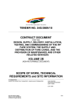
6.2
Mechanical Drawings
12-02-2003
Page 6-40 of
51
- 6-40 -
7 Appendix
7.1
Seiko compatible command set (optional)
7.1.1 Escape sequences, overview.
CR
ESC+ ‘ J ’ +n
ESC+ ‘ j ’ +n
ESC+ ‘ 2 ’
ESC+ ‘ 0 ’
ESC+ ‘A’+n or ESC+ ‘3’+n ndot
ESC+ SP+n
ESC+ ‘ s ’+nl+nr
ESC+ ‘ U ’+n
DC2+ ‘ Y’ +n
ESC+ ‘ - ’ +n
SO
DC4
ESC+ ‘ W ’+n
ESC+ ‘ w ’+n
ESC+ ‘ I ’+n
DC2+ ‘ F ’+n
ESC+ ‘ t ’+n
ESC+ ‘ & ’ + s + e+
ESC+ ‘ % ’ + n
DC2+ ‘ D ’+n
ESC+ ‘+’ + k1 + k2+
FS+ ‘ 2 ’ + k1 + k2+
ESC+ ‘ K ’ or FS+ ‘ & ’
ESC+ ‘ H’ or FS+ ‘. ’
DC2+ ‘ G ’+n
12-02-2003
Page 7-41 of
51
CR Carriage Return
Print and Feed Forward
Print and Feed Backward
16-dot Line Spacing
4-dot Line Spacing
Line Spacing
Character Spacing
Left/Right Character Spacing
Inverse Print
Character Rotation
Underline
Double-Width (with automatic reset )
ON
Double-Width (with automatic reset)
OFF
Double-Width
Double-Height
Reverse
Font Size Selection
Character Set Select
Font Data Downloaded Character
Define
Downloaded Character Select
Downloaded Character Area Operation
ESC+ ‘+’ + k1 + k2+ Font Data
Font Data User-Defined Character
Define
Kanji Mode Specify
Kanji Mode Clear
User Defined Character Area
Operation
- 7-41 -
DC2+ ‘ P ’ + s + e+ x + y +
DC2+ ‘ O ’+n
DC2+ ‘ Q ’
DC3+ ‘ A ’
DC3+ ‘ B ’
DC3+ ‘ V ’ +
DC3+ ‘ D ’+nl+nh
DC3+ ‘ L ’+ml+mh+nl+nh
DC3+ ‘ F ’+n1+n2
Font Data Option Font Define
Option Font Select/Deselect
Option Font Clear
Ruler Line Buffer A
Ruler Line Buffer B
Image Data Ruler Line Image
Define Ruler Line by Dot
Define Ruler Line by Line
Define Ruler Line with Repeating
Pattern
Ruler Line ON
Ruler Line OFF
Print One Dot Line after Printing Line
Buffer Data
Ruler Line Buffer Clear
Continuous Ruler Line Control Code
Input
DC3+ ‘ + ’
DC3+ ‘ - ’
DC3+ ‘ P ’
DC3+ ‘ C ’
DC3+ ‘ (’
7.2
Fujitsu compatible command set (optional)
7.2.1 Escape sequences, overview.
HT
LF
FF
ESC RS:
ESC US:
ESC !+n:
ESC %+n:
ESC &+y+c1+c2+x+[d]k
:
ESC *+m+n1+n2+[d]k
:
ESC ?+n
ESC 2
ESC 3+n
12-02-2003
Page 7-42 of
51
Horizontal tab
Line feed with printing
Forms feed
Black-white reversed printing specification
Black-white reversed printing cancellation
Printing mode specification
Download character set
specification/cancellation (valid only when
optional memory is installed)
Download character definition (valid only
when optional memory is installed)
Bit image mode specification
External registration character deletion (valid
only when optional memory is
1/6-inch line pitch setting
Minimum-pitch-unit line pitch setting
- 7-42 -
ESC @
ESC A+n
ESC C+n
ESC D+[n]k+NUL
ESC J+n
ESC K+n
ESC R+n
ESC c+1+n
ESC d+n
ESC e+n
ESC s+n
ESC t+n
ESC {+n
FS 9+n
GS <
GS A+m+n
GS E+n
GS V+n+m
GS e+n+m
GS h+n
GS k+m+n+[d]k
GS w+n
FS *+n1+n2+[n]k
GS &+m+x+y1+y2+[n]k
GS '+m+n
FS E+n
ESC V+n
GS a+n
FS r+n
ESC EM+n
ESC X+n+m
Line Feed
[Name]
[Format]
12-02-2003
Page 7-43 of
51
Line Feed
ASCII
Hex
Decimal
Printer initialisation
Line spacing setting
Page length (number of lines) setting
Horizontal tab position setting
Printing and minimum-pitch-unit paper feed
Backward paper feed
International character specification
Internal processing setting
Printing and n-line feed
Printing and backward n-line feed
Printing speed setting
Character code table selection
Upside-down printing setting/cancellation
Detection function enable/disable setting
Mark detection execution
After-mark-detection head detection
distance setting
Print quality setting
Paper cutting
Bar code width setting
Bar code height setting
Bar code printing
Bar code width magnification setting
High speed collective image printing
specified
Registration of image data
Print registered image data
Correction of impressed energy
Right rotation 90º
Setting and cancellation of status
transmission.
Parameter transmission
Setting the amount of the feeding at
automatic paper feed
Setting the turning time of the motor
excitation
LF
0A
10
- 7-43 -
[Description]
When the printer controller receives this byte the text
data in the buffer will be printed
Horizontal tab
[Name]
Horizontal tab
[Format]
ASCII
HT
Hex
0A
Decimal
10
[Description] When the printer controller receives this byte the text
data in the buffer will be printed
12-02-2003
Page 7-44 of
51
- 7-44 -
7.3
APS compatible command set (optional)
7.3.1 Escape sequences, overview.
GS / n
GS D n
ESC v
ESC I
ESC @
ESC S
GS B n
GS b n
ESC % n
ESC R n
ESC 3 n
ESC SP n
ESC ! n
ESC { n
LF
CR
ESC J n
ESC j n
CAN
ESC * n1 n2 n3 n4 n5 n6, data
ESC $ n1,n2
ESC V n1,n2,n3 data
ESC m
ESC i
GS k n [Start] <data> NUL
GS h n
GS w n
GS H n
GS L n
GS T n Se
GS E
GS X n1 n2
GS x n1 n2
Set printing speed / Maximum peak current
Set print Intensity
Send printer status
Send printer identity
Resets printer
Puts the printer in sleep mode
Serial Communication setting
Set parallel port Busy line hold time
Select internal Character Set
Select international character Set
Set line spacing
Set character spacing
Set print mode
Set/reset Rotated character
Line feed
Carriage return
Feed paper (n dot lines) forward
Feed paper (n dot lines) backward
Cancel print data buffer (text mode)
Print graphics
Horizontal dot positioning
Horizontal bit image
Partial cut
Full cut
Print bar code
Barcode Height
Barcode magnification
Text position in Barcode
Set Mark length
Set TOF position
TOF feed paper
Set Mark to Cut Position
Set Cut Line to Head Dot line Length
GS / n
12-02-2003
Page 7-45 of
51
- 7-45 -
Description:
Format:
Comments:
Example:
GS D n
Description:
Format:
Comments:
Set printing speed / Maximum peak current/
Dynamic division
<1Dh> <2Fh> <n>
n=1 to 32: (Default n=5) Software programmable
consumption (Dynamic division). The
maximum number of black dots which are
simultaneously heated is (n+1) x 8.
In Default Mode, n = 5.
n=5 Maximum black dots heated: (5+1)*8=48.
Printer Peak consumption @5V: (0.3A (Stepper
Motor) + 5*48/160) = 1.8A
160 Ohms is the dot resistance.
Set print Intensity
<1Dh> <44h> <n>
n=8Fh (127d) : (Default). Nominal print intensity
n>8Fh (127d) : Printout becomes darker
n<8Fh (127d) : Printout becomes lighter
(n from 0 to 255 (FFh)).
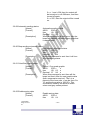
ESC v
Description:
Format:
Comments:
Send printer status
<1Bh> <76h>
The printer returns a single byte that reflects the
status of the printer in accordance with the
following table:
BIT FUNCTION BIT = 0 BIT = 1
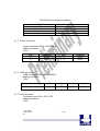
0 Head temperature OK Too high or too low
1 Head-up No Yes
2 Paper out No Yes
3 Power supply OK Too high or too low
4 Printer in use Ready Action in progress
5 On/Off line Off On
6 Hole/Mark detection Error No Too short, too long or not found
7 Cutter failure Yes No
This command is executed immediately after being received, even in
case of a full buffer
(DTR/RTS, Xoff or Busy active). Host must disable the handshaking
controls to send the ESC v
command.
When using the parallel port, the software continuously updates PE
signal. To read the
status byte, use the Byte Mode (Parallel communication) as described
in section 3.4.2, after
having sent the ESC v command.
12-02-2003
Page 7-46 of
51
- 7-46 -
7.4
ESC/POS compatible command set (optional)
7.4.1 Escape sequences, overview.
ESC c 4
HT
LF
FF
CR
DLE EOT n
DLE ENQ n
CAN
ESC FF
ESC SP n
ESC ! n
ESC$ nL nH
ESC * m nL n H
[d]k
ESC - n
ESC 2
ESC 3 n
ESC = n
ESC ? n
ESC @
ESC [n] k NUL
ESC E n
ESC G n
ESC J n
ESC L
ESC R n
ESC S
ESC T n
ESV V n
ESC W xL xH yL
yH dxH dyL dyH
ESC c 5 n
ESC c 3 n
ESC a n
ESC \ nL nH
12-02-2003
Page 7-47 of
51
Select Paper Near End Sensors to stop printing
Horizontal Tab
Print and Line feed
Print and return to standard Mode
Print and carriage return
Real Time status transmission
Real time request to printer
Cancel print data in page mode
Print data in page mode
Set right side character spacing
Select print mode(s)
Set absolute print position
Select bit image mode
Turn underline mode on/off
Select 1/6-inch spacing
Set line spacing
Set peripheral device
Cancel user defined characters
Initialize printer
Set horizontal tab position
Turn emphasized mode on/off
Turn on/off double strike mode
Print and feed paper
Select page mode
Select an international character set
Select standard mode
Select print direction in page mode
Turn 90°clockwise rotation mode on/off
Set printing in page mode
Enable/Disable panel buttons
Select paper near end sensors to output end
signals
Select justification
Set relative print position
- 7-47 -
ESC d n
ESC i
ESC p m t1 t2
ESC t n
ESC u n
ESC v
ESC { n
GS ! n
G S $ nL nH
GS * x y [d] x*y *8
GS / m
GS :
GS B n
GS H n
GS I n
GS L nL nH
GS P x y
GS V m n
GS W nL nH
GS \ nL nH
GS ^ r t m
GS a n
GS b n
GS f n
GS h n
GS k m d1…dk
NUL
GS k m n d1…dn
GS r n
GS w n
12-02-2003
Page 7-48 of
51
Print and feed n lines
Partial cut
Cash drawer Output
Select character Code table
Transmit peripheral device status
Transmit paper sensor status
Turns on/off upside-down printing mode
Select character size
Set absolute vertical print position in page mode
Define download bit image
Print downloaded bit image
Start / end macro definition
Turn white/black reverse printing mode
Select printing position for HRI characters
Transmit printer ID
Set left margin
Set horizontal and vertical motion units
Select cut mode and cut paper
Set printing area width
Set relative vertical print position page mode
Execute macro
Enable /Disable Automatic Status back
Turns smoothing mode on/off
Select font for Human Readable Interpretation
(HRI) characters
Select bar code height
Print bar code
Print bar code
Transmit status
Set bar code width
- 7-48 -
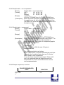
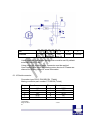
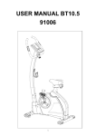
7.5
Optional sensor description
Top view
PIN1
PIN2
PIN3
Bottom view
12-02-2003
Page 7-49 of
51
- 7-49 -
Please note that distance from top of sensor to paper must be Min
0,5mm and Max 1,00mm
12-02-2003
Page 7-50 of
51
- 7-50 -
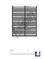
RED
RED
WHITE
BLACK
RED
WHITE
BLACK
Example showing how to connect PRS600 to AUX Input connector CN4
on PRN604-S standard board.
12-02-2003
Page 7-51 of
51
- 7-51 -