1
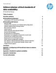
AC 2009-1756: INTERFACING THE USB PRINTER INTERFACE USING
VINCULUM HOST CONTROLLER
Gurinder Singh, Future Technology Devices International Ltd. (USA)
Gurinder Singh brings almost a decade of experience in the electronics industry to his position as
Senior Field Applications Engineer with Future Technology Devices International Ltd. At FTDI
Gurinder is actively involved in embedded USB HOST designs, application notes, technical
support on USB devices and HOST controllers, guiding customers to obtain WHQL certifications
and USB 2.0 compliance certifications along with providing sample codes and professional
manufacturing test tools for production lines using USB devices in their products. Gurinder also
provide technical guidelines to implement USB devices on Windows mobile platform like Win
CE 5.0, Windows Mobile 6.0. He is also involved in writing firmware for our products and we are
successfully launching USB-CAN sniffer and RS232-CAN monitor products based on his
excellent work.
Lakshmi Munukutla, Arizona State University
Lakshmi Munukutla received her Ph.D. degree in Solid State Physics from Ohio University,
Athens, Ohio and M.Sc and B.Sc degrees from Andhra University, India. She has been active in
research and published several journal articles. She is a professor in the Department of
Engineering Technology at Arizona State University at the Polytechnic campus.
Page 14.783.1
© American Society for Engineering Education, 2009
Interfacing USB Printer using Vinculum Host Controller
Abstract
This paper describes implementation of a portable USB printer interface using Vinculum
Host Controller VNC1L. The project idea presented has a variety of real-world applications
including in medical portable devices, field testing devices, ticketing systems, gas receipt
printing system to name a few.
Today almost all the printers have a Universal Serial Bus (USB) interface for connection
to a personal computer (PC) or a control device. The USB interface has several advantages over
previous generation of connection methods such as parallel ports. A USB port is much faster
than a parallel port (can handle 12Mbps) and a single port can handle different devices. For
example, a USB port can handle flash disks, mouse, keyboard, etc. whereas the parallel port was
pretty much dedicated for the printer connection.
In this paper we present an embedded micro-controller based control device that has a
USB controller port with printer interface and can be operated on a battery. This paper will
describe the details how the Vinculum USB Host controller is used to implement interface to
USB print class devices with Freescale HC-12 used to control VNC1L. It is very important for
technical students to gain familiarity with USB. This application can be used to understand
embedded/non-PC usage of USB devices. The possibility of using this as a classroom USB
project is also explored in this paper.
1. Introduction
Universal Serial Bus (USB) is an input/output port standard for computers and digital equipment
that allows easy transfer of data at high speeds via a direct connection or cable. A USB
connection is always between a host or hub at the "A" connector end, and a device or hub's
upstream port at the other end. Typically, personal computer implements the USB host controller
and has built-in hub to provide multiple USB ports. In embedded applications, a micro-controller
unit (MCU) with built-in host controller or a discrete USB host controller module is used to
provide connectivity for USB devices. In the application design presented in this paper Vinculum
Host Controller is used along with a Motorola MCU to implement USB printer interface.
Page 14.783.2
The USB enumeration process happens when a device is plugged to the USB host controller. The
host controller handles the device requirements using standard USB descriptors supplied by
device. USB 2.0 specification defines a specific device class for printing devices. VNC1L USB
Host controller implements and supports USB print class device, configuration, and interface and
endpoint descriptors as per USB printer device specification. It also supports USB printer class
specific request and response structure used by basic Printer Command language (PCL)
interface.
Most modern printers support built-in fonts and as such they can print text, using basic printer
control codes, directly from the Vinculum Monitor. Other printers will require embedded fonts
or graphics to be sent as part of a print job. Most modern printers support a PCL language as the
protocol for an operating system driver to communicate with the printer. If the printer supports
PCL language it can be controlled by the VNC1L using the methods outlined in this paper.
2. USB Printer Class
USB Printer Class specification defines three class-specific requests – GET_DEVICE_ID,
GET_PORT_STATUS and SOFT_RESET.
2.1 GET_DEVICE_ID (bRequest = 0)
This class-specific request returns a device ID string that is compatible with IEEE 1284. See
IEEE 1284 for syntax and formatting information. A printer with multiple configurations,
interfaces, or alternate settings may contain multiple IEEE 1284 device ID strings. The
wValue field is used to specify a zero-based configuration index. The high-byte of the
wIndex field is used to specify the zero-based interface index. The low-byte of the wIndex
field is used to specify the zero-based alternate setting.
2.2 GET_PORT_STATUS (bRequest = 1)
This class-specific request returns the printer’s current status, in a format that is compatible
with the status register of a standard PC parallel port. Table 1 defines the data returned.
Bits
7-6
Field
Reserved
Description
5
Paper Empty
1 = Paper Empty, 0 = Paper Not Empty
4
Select
1 = Selected, 0 = Not Selected
3
Not Error
1 = No Error, 0 = Error
2-0
Reserved
Reserved for future use
Reserved for future use
Table 1 GET_PORT_STATUS return byte details
2.3 SOFT_RESET (bRequest = 2)
This class-specific request flushes all buffers and resets the Bulk OUT and Bulk IN pipes to
their default states. This request clears all stall conditions. This reset does NOT change the
USB addressing or USB configuration.
3. VNC1L Printer Interface Design
Page 14.783.3
shows the block diagram and connections between the various devices used in the
printer application described in this paper. An FTDI V-Eval board is used as the base
development platform. The V-Eval board includes the VNC1L device, prototyping area, external
connectors and two USB Host ports. An external microcontroller is required to control the
VNC1L. A Freescale micro-controller on a daughter board is connected to the V-Eval on the SPI
bus.
Figure 1
The VNC1L monitor port is selected on V-Eval board through jumper settings. Three interface
options are possible – UART, SPI and FIFO. In this set-up the monitor port SPI interface was
used. The Freescale micro-controller is then connected to the V-Eval SPI header.
When a printer is attached to Type A USB port of the V-Eval board, it gets enumerated and a
status message is sent on the monitor port that is captured by the HC12 micro-controller. The
VNC1L has two modes of commands - text based command and binary commands. To reduce
the bandwidth on the SPI bus, the binary command set (also called the Short Command Set) is
used.
In the micro-controller unit firmware, pressing switch SW1 on the V-Eval board generates a set
of PCL commands that are sent to the VNC1L on the V-Eval board via the SPI interface.
VNC1L sends the corresponding data on the USB to the printer. The printer takes the data,
parses it using PCL and prints the data to the paper. The LED7 and LED8 on V-Eval board are
used for indicating the status of printer.
The same concept can be implemented in Windows Mobile devices (based on Win CE) that
interface with Vinculum chip on monitor port. Applications can be written to send PCL
commands to the printer.
SW1
Freescale
HC12
Microcontroller
SPI
M
USB-2
o
n
i Vinculum VNC1L
t
o
USB-1
r
HP DeskJet 460
Daughter
board
V-Eval Board
Figure 1 Block Diagram of VNC1L USB Printer Interface
Page 14.783.4
4. VNC1L Printer Interface Commands
VNC1L is used in the command mode to send commands to the printer. VNC1L USB Host
controller uses standard commands to set up the communication channel and check the status of
slave device (printer). The commands relevant to this application are tabulated in Table 2 and
described below.
Extended Command Set
Function
QP1
Short Command Set
(Hexadecimal Codes)
2B 0D
QP2
2C 0D
Query port 2
QD·byte
85 20 byte 0D
Query device specified in the 1st
parameter
SC·byte
86 20 byte 0D
Set device specified in the 1st
parameter as the current device
DSD·byte
data
83 20 byte 0D data
Send data to USB device where the
size of the data is specified in the 1st
parameter
DRD
84 0D
Read back data from USB device
SSU·qword
(data)
9A 20 qword 0D
(data)
Send setup data to device control
endpoint with optional follow-on data
SF·byte
87 20 byte 0D
Set device specified in the 1st
parameter as an FTDI device
QSS
98 0D
Query port 1
Query Slave Status (only available on
VDPS)
Table 2 USB Device Commands
5. Printer PCL Commands
Printer Command Language or PCL was first developed by HP as a printer protocol and has
since become a de-facto industry standard.
Page 14.783.5
PCL commands provide access to the printer’s PCL control structure. The PCL structure controls
all of the printer’s features except those used for vector graphics, which are controlled by the
HP-GL/2 commands. PCL printer commands consist of two or more characters. The first
character is always the Ascii escape character, identified by the decimal value of “027” or
hexadecimal value of “1B”. Escape character is a special control code which identifies the
subsequent string of characters as a printer command. As the printer monitors incoming data
from a computer, it “polls” for this character. When this character appears, the printer reads it
and its associated characters as a command to perform and not as data to print.
The PCL commands used in this paper are as follows. For further details on PCL commands
please refer to HP PCL Reference Manual; Printer Control Language Reference Manual.
Printer Reset (EC E): Restores the User Default Environment, deletes temporary fonts and
macros, and prints any remaining data.
Number of Copies (EC & l # X): Prints the specified number (#) of copies of each page.
Page Size (EC & l # A): Designates the physical paper size which in turn defines the logical
page. # = 2 - Letter (8.5" x 11")
Left Margin (EC & a # L): Sets the left margin to the left edge of the specified column. # =
Column number
Right Margin (EC & a # M): Sets the right margin to the right edge of the specified column. #
= Column number
Line Termination (EC & k # G): Controls the way the printer interprets CR, LF, and FF
control codes. # = 0 - CR = CR, LF = LF, FF = FF
Font Selection by ID # (EC ( # X or EC ) # X): Selects a soft font using its specific ID #. EC (
# X - Designates soft font as primary. EC ) # X - Designates soft font as secondary. # = Font
Identification number
Spacing (EC ( s # P – Primary, EC ) s # P – Secondary): Designates either a fixed or
proportionally spaced font. # =0 means Fixed spacing, # - 1 means Proportional spacing
Pitch (EC ( s # H – Primary, EC ) s # H – Secondary): Designates the horizontal spacing of a
fixed spaced font in terms of the number of characters per inch. # = Pitch in characters/inch
Stroke Weight (EC ( s # B – Primary, EC) s # B – Secondary): Designates the thickness or
weight of the stroke that composes the characters of a font.
6. HC-12 Firmware Details
The firmware begins by initializing the processor resources. Programmable resources include
RAM address location, I/O definitions, SPI, UART and EEPROM. Only the resources that are to
be used in the project need to be initialized. By default, the processor initializes resources to be
disabled and I/O to be input pins and SPI mode is enabled. The program is also configured for
UART communication with the VNC1L with possibility of allowing RS-232 communication at a
later time.
After the system is initialized, the program enters the main loop, which scans for time based
events or asynchronous events. At any time, the main loop can be interrupted for processing
interrupt events such as timers or RS-232 input.
MAIN: This is the program loop that runs all of the routine operations of the system. This
includes waiting for time based functions, scanning for keys, and checking for new messages
from the VNC1L.
Page 14.783.6
For this demonstration, only a single key is being scanned. But note that for any keys that are
used, a de-bounce routine should be used to eliminate erroneous key presses. Keypads and
switches are notorious for ringing as the key is pressed and released. As soon as key is pressed,
DSD command with PCL control codes is given to VNC1L chip on SPI bus which results in
printing the data on printer connected on USB port of VNC1L.
The Main loop also scans the VNC1L for any new messages. When a new message is detected,
it is read and parsed to determine if any further action should be taken. For example, when a
new device is connected, it should be polled to indentify the device type and device number.
INTERRUPTS: Two interrupts are used for this demonstration. One is for timekeeping; the
other is to run the RS-232 interface. The CPU timer register is configured to increment every 4
bus clocks. The bus is driven by a PLL and is configured for a 23.9616 MHz clock.
TIMER: This routine is triggered once every 5990 timer ticks, or every 1 mS. Each of the mS
interrupts are counted and stored in variables so that the Timer_Flag bits can be set to identify
periodic time events.
The RS-232 interrupt is used to receive data from the USB port, which should be connected to a
PC running a terminal program at 115,200 baud. Each byte that is received triggers an interrupt
that gets the incoming character and stores it to a buffer. When a form feed command (0x0C) is
received, the incoming data is then sent to the VNC1L to be printed. If a form feed is not
received, any data in the input buffer is printed after timer based pre-configured timeouts.
There are ten major routines in the HC12 firmware developed for this project. The brief
explanation of each routine is given here.
1.
2.
3.
4.
5.
6.
7.
8.
9.
10.
USB_INIT - Initializes the VNC1L chip and sets the command mode to Short Command
Set (SCS - Hexadecimal format)
USB_QUERY - Checks if any new data is available from VNC1L chip
USB_READ - Reads data from the VNC1L chip
USB_WRITE - Sends known length Command/Data to the VNC1L chip
USB_WRITECMD - Sends null terminated data to VNC1L chip
USB_PARSE - Processes the data received from VNC1L chip and determines the action to
take
GET_DEVICE_TYPE - Determines which device is connected to the VNC1L USB port
RUNSPI - Sends the data through SPI interface by loading the data in register “REG A”
INIT_PRINTER - Selects and sets up the printer connected to VNC1L USB port
USB_PRINT - Sends the VNC1L “DSD” command with the data string to the printer for
printing
7. Classroom/Laboratory Project
It is important that technical students learn about USB and perform USB based hands-on
application development in laboratory/classroom environment. VNC1L based USB printer
interface design is one such useful application students can experiment with that exposes them to
hands-on learning on various topics they will find useful when working in industry.
1. Implement a firmware routine for USB_READ or any other, assemble and flash the
HC12
3. Familiarize with PCL commands
Page 14.783.7
2. Monitor various USB packets exchanged during the device enumeration process using a
USB sniffer tool
4. Take input from DIP switches or Analog input to modify the printed page to include
input value
8. Summary
This paper described how a USB printer interface can be added to an embedded system using
Vinculum USB Host controller VNC1L. A 16-bit Freescale HC12 microcontroller has been used
to control the VNC1L chip using SPI interface on V-Eval board and give PCL commands to the
printer. In this paper, background on USB, USB printer class, PCL commands, hardware, and
firmware implementation for USB printer interface have been presented.
It is important that technical students learn about USB and perform USB based hands-on
application development in laboratory/classroom environment. VNC1L based USB printer
interface design is one such useful application students can experiment with that exposes them to
hands-on learning on serial SPI interface, USB details, PCL commands, HC12 firmware
development etc. This exercise can be part of microprocessor applications course.
9. References
1. Vinculum Website: The main website for the Vinculum family of USB Host Controllers on
the FTDI website http://www. ftdichip.com/
2. Vinculum Datasheet (DS_VNC1L-1A): Vinculum Embedded USB Host Controller IC Data
Sheet http://www. ftdichip.com/
3.
USB Device Class Definition for Printing Devices
http://www.usb.org/developers/devclass_docs/usbprint11.pdf
4. HP PCL Reference Manual; Printer Control Language Reference Manual
http://h20000.www2.hp.com/bc/docs/support/SupportManual/bpl13210/bpl13210.pdf
5. HC12 Assembler User Manual
http://www.freescale.com/files/microcontrollers/doc/user_guide/MCUEZASM12.pdf
Page 14.783.8