1
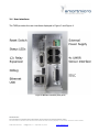
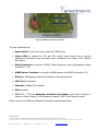
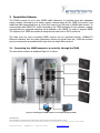
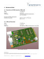
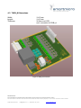
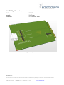
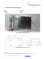
1 Traffic Management Interface Board Data Sheet
1.1 General Information
The Smartmicro TMIB (Traffic Management Interface Board) connects up to four UMRR
Radar sensors (traffic detectors) to NEMA TS1 or TS2 cabinets (TMIB rack mount version); or
to other traffic controllers (TMIB shelf mount version).
A TMIB set consists of two cards. The TMIB_AB assembly is the control board plus the
interface board. This second board contains all surge and overvoltage protection circuitry for
four long cables to four sensors, as it is the typical case on an intersection. One TMIB set can
replace up to 16 inductive loops (TS1 usage) / up to 64 inductive loops (TS2 SDLC usage, up
to four TS2 BIUs replaced).
The data of all four Radar sensors can be accessed conveniently through one single 100BaseTX Ethernet interface.
Rack-mount use:
In a typical (rack mount) installation, the TMIB consists of two NEMA form factor
cards: The TMIB_AB assembly consisting of TMIB_A featuring TS1 loop contacts and
status LEDs as well as the TMIB_B, which contains the sensor interface connections
and the RS485/SDLC bus connectivity for TS2 cabinets. One TMIB can be connected
to up to four “Inductive Loop Detector Unit” slots, replacing 16 inductive loops. In
addition, up to three TMIB_C expansion cards may be installed. Each TMIB_C card
offers four loop detector outputs. In NEMA TS1 installations they can be used to
connect additional relay contacts to the traffic cabinet, because each TS1 card is
limited to a maximum of four loop detector outputs.
Shelf-mount use:
In a typical (shelf mount) installation, the TMIB_AB assembly resides within an
enclosure, offering all interfaces to the user.
The TMIB is well integrated in smartmicro’s TMC (Traffic Management Configurator) PC
software to give the installer a powerful and easy-to-use tool for setup and maintenance.
Please note: TMIB_A/B/C are not fully fail-safe devices. While a number of steps have been
taken to make sure the devices show a fail-safe behavior, this cannot be assured under all
conditions. The connected sensors (detectors) do not have 100% detection rate or zero false
alarm rate (see data sheet). In case of communication problems, sensor failure, TMIB_A/B/C
failure in part or in whole, under certain condition a non-fail-safe behavior may occur.
PROPRIETARY
The information contained in this document may be subject to change without notice.
The information contained in this document shall remain the sole exclusive property of s.m.s smart microwave sensors GmbH.
TMIB Data Sheet.doc I Page 2 of 17 I September 18, 2015
www.smartmicro.de