1
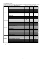
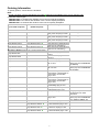
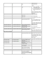
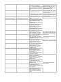
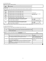
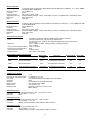
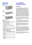
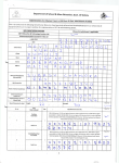
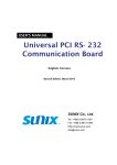
Loop-AM3440 Access DCS-MUX AM3440-A Description The Loop-AM3440-A/B/C are Access DCS-MUXs that can combine various digital access interfaces into E1 or T1 lines for convenient transport and switching. The Loop-AM3440 Access DCS-MUX provides access for a variety of TDM, IP, and voice interfaces detailed on next page. These interfaces are compatible with other Loop products. Using these products, a DTE interface can be extended over copper wire pairs or any E1/T1 transport facility. For each Quad E1/T1 plug-in card, each card can have as many as DS0 124/96 time slots from G.SHDSL, RS232, X.21, V.35, V.36 and EIA530/RS449 interfaces, which can be multiplexed to fill 4 E1/T1 lines. AM3440 also supports fiber optical plug-in card, which can be used to aggregate up to 4 E1 channels onto a single fiber optical interface to connect with other AM3440 or O9310. AM3440-B AM3440-C Each of the 3 models of AM3440, the A, the B, and the C, has a number of plug in slots in single slot size and mini size as shown in table at left. Card size to slot compatibility detailed on next page. Features y y y y y y y y y y y Full front access (ETSI) Shelf Support of DS0 DACS (Digital Access Cross-Connect System) with full cross-connect Dual controller, dual power with load sharing 1 for 1 protection, Y-BOX 1 for 1 protection, E1, T1, FOM PDH ring protection, QE1, QT1, FOM, Mini QE1 Console, Telnet, SLIP, SNMP, and Inband management support Craft interface port for connection to external LCD display Compatible to a SNMP based GUI network management system and supported by LoopView and Loop iNMS Three types of chassis available: AM3440-A/AM3440-B/AM3440-C All the plug-in cards are hot-pluggable Item AM3440-A AM3440-B AM3440-C Chassis 5U 2.5U 3U # of Mini-slots 4 4 4 # of Single slots 12 3 5 Max. E1 Channels 64 28 36 Max. T1 Channels 52 16 24 Cross-Connect Backplane Capacity 128 Mbps 56 Mbps 72 Mbps This unit is a full cross-connect and can act as a mini DACS. This means that one or more of the WAN ports can be used as a Drop & Insert function with fractional E1/T1 lines, which can be muxed into a full E1/T1 line. Redundancy is available in dual CPU controller and power supply options, making it an excellent fit for critical applications. Although the chassis does not contain and has no need for fan cooling, an external fan tray is available. The Loop-AM3440 supports local control and diagnostics by using an external 2-line by 40-character LCD display and keypads, or by using a VT-100 terminal connected to the console port. The Loop-AM3440 also supports Ethernet, SLIP, Telnet, and SNMP, so that it can be controlled and diagnosed from remote locations as well. An in-band management channel with GUI is available. In addition to the LCD display, there is LED indication for all plug-in cards. Finally, the Loop-AM3440 consists of a rugged reinforced aluminum chassis, giving this equipment a more durable structure and a longer physical life. 1 Loop-AM3440 cards: The Mini-Slot Cards plug into the Mini-Slots of the AM3440. The Single-Slot Cards plug into single slots, and the Dual-Slot Cards plugs into two adjacent single slots. Plug-in cards AM3440-A AM3440-B AM3440-C 1-channel E1 (Single E1 interface) √ √ √ 1-channel T1 (Single T1 interface) √ √ √ Mini Quad E1 (Four E1 interfaces) √ √ √ 1-channel E1 ATM/Frame Relay √ √ √ 1-channel T1 ATM/Frame Relay √ √ √ 2-LAN port/32 WAN port Router √ √ √ 2-LAN port/64 WAN port Router-A √ √ √ Fiber optical interface Mini-Slot √ √ √ 3-channel Terminal Server √ √ √ 1-channel X.21 √ √ √ 1-channel V.35 √ √ √ 1-channel RS232 √ √ √ 1-channel EIA530 √ √ √ Quad 2W/4W E&M (Four E&M voice interfaces) √ √ × QFXS/QFXO (Four FXS/FXO voice interfaces) √ √ × 3-channel E1 (future option) √ √ √ 4-channel E1 √ √ √ 4-channel T1 √ √ √ 2-channel G.SHDSL (2 pairs) w/o line power √ √ √ 4-channel G.SHDSL (1 pair) w/o line power √ √ √ 8-channel G.703 card at 64 Kbps data rate √ √ √ 8-channel Dry Contact I/O √ √ √ 8-channel Dry Contact I/O type B √ √ √ Single-Slot 8-channel 2W/4W E&M √ √ √ 12-channel FXS √ √ √ 12-channel FXO √ √ √ 12-channel Magneto √ √ √ 1-channel low speed optical (C37.94) √ √ √ 4-channel low speed optical (C37.94) √ √ √ 8-channel RS232 with X.50 subrate √ √ √ 8-LAN-port/ 64-WAN-port Router-B √ √ √ Conference card √ √ √ 6-channel X.21/V.11 √ √ √ 6-channel V.35 √ √ √ 6-channel V.36 √ √ √ 6-channel EIA530/RS449 card √ √ √ 5-channel RS232 with X.50 subrate Dual-Slot √ √ √ 24-channel FXS √ √ √ 24-channel FXO √ √ √ 2-channel G. SHDSL (2 pairs) with line power √ × × 4-channel G. SHDSL (1 pair) with line power √ × × Note: √ = Supported × = Not supported 2 Ordering Information To specify options, choose from the list below: Note: 1. RoHS compliant units are identified by the letter G appearing immediately at the end of ordering code. 2. AM3440 chassis types: AM3440-CHA: 5U chassis with 128 Mb/s cross-connect capacity backplane AM3440-CHB: 2.5U chassis with 56 Mb/s cross-connect capacity backplane AM3440-CHC: 3U chassis with 72 Mb/s cross-connect capacity backplane Model (non RoHS compliant) Model (RoHS compliant) Main Unit Loop-AM3440-CHA Loop-AM3440-CHA-G Loop-AM3440-CHB Loop-AM3440-CHB-G Loop-AM3440-CHC Loop-AM3440-CHC-G CPU Module Loop-AM3440-CCA-T Loop-AM3440-CCA-T-G Loop-AM3440-CCA-E Loop-AM3440-CCA-E-G Mini Plug-in Module (Select 1 to 4 cards from list below) Loop-AM3440-E75-G Loop-AM3440-E75 Description Wideband Main Unit without CPU, power and plug-in cards Wideband Main Unit without CPU, power and plug-in cards Wideband Main Unit without CPU, power and plug-in cards Note AM3440-A type Chassis AM3440-B type Chassis AM3440-C type Chassis CPU card with T1 External Clock (order two for redundancy) CPU card with E1 External Clock (order two for redundancy) Loop-AM3440-T1 Loop-AM3440-M4E75 Loop-AM3440-T1-G Loop-AM3440-M4E120 Loop-AM3440-M4E120-G Loop-AM3440-AFRE Loop-AM3440-AFRE-G Loop-AM3440-AFRT Loop-AM3440-AFRT-G Loop-AM3440-RT Loop-AM3440-RT-G Loop-AM3440-RTA Loop-AM3440-RTA-G Loop-AM3440-FOM-opt Loop-AM3440-FOM-opt-G Loop-AM3440-TS Loop-AM3440-TS-G Not available Not available Loop-AM3440-1X21-G 1-channel of E1plug-in card w/ 75 ohm 1-channel of E1 plug-in card w/ 120 ohm 1-channel T1 plug-in card Mini Quad E1 plug-in card Includes a one meter conversion with 75 ohm cable (Loop-ACC-CAB-DB25M100-8BNCM) Mini Quad E1 plug-in card Includes a one meter conversion with 120 ohm cable (Loop-ACC-CAB-DB25M100-4RJ48M) E1 Frame Relay to ATM inter-working or Frame Relay to Frame Relay concentration plug-in card T1 Frame Relay to ATM inter-working or Frame Relay to Frame Relay concentration plug-in card 2-LAN ports/32 WAN port Router/Bridge plug-in card 2-LAN ports/64 WAN port router/bridge plug-in card Fiber Optical plug-in card For opt option, please refer to the table below for detail information 3-chanel Terminal Server Includes a one meter conversion plug-in card cable (Loop-ACC-CAB-DB44M -100- 2DB25F-1DB09F-TS) 1-channel X.21 plug-in card Loop-AM3440-1RS232- G 1-channel RS232 plug-in card Loop-AM3440-1V35- G 1-channel V.35 plug-in card Loop-AM3440-1E530- G 1-channel EIA530 plug-in card Loop-AM3440-E120 Not available Not available Loop-AM3440-E120-G Loop-AM3440-M4E75-G 3 Loop-AM3440-Q2EM-m-Tn Loop-AM3440-Q2EM-m-Tn-x- Quad 2 Wire E&M voice plug-in AM3440-CHB and card AM3440-CHC only -x G Where m = B for normal E&M or TO Loop-AM3440-Q4EM-m-Tn Loop-AM3440-Q4EM-m-Tn-x- Quad 4 Wire E&M voice plug-in (transmission only) card -x G = A for tandem operation n = 1 to 5 E&M Signaling Type = O for TO (transmission only) For m, n and x option, please refer to the table below for detail information Quad FXS voice plug-in card AM3440-CHB and Loop-AM3440-QFXS-x Loop-AM3440-QFXS-x-G Quad FXS with MP 16 KHz voice AM3440-CHC only Loop-AM3440-QFXS-M-x Loop-AM3440-QFXS-M-x-G plug-in card Loop-AM3440-QFXS-M12- Loop-AM3440-QFXS-M12-x-G Quad FXS with MP 12 KHz voice GS = Ground Start plug-in card x Loop-AM3440-QFXS-GS-x Loop-AM3440-QFXS-GS-x-G Quad FXS with GS plug-in card MP = Metering Pulse Transmit 12/16 KHz Loop-AM3440-QFXS-GM-x Loop-AM3440-QFXS-GM-x-G Quad FXS with GS and MP 16 KHz voice plug-in card For -48 Vdc (SDB) and 100 to 240 Vac (SAB) power supply only. Quad FXO voice plug-in card Quad FXO with MP 16 KHz voice plug-in card Loop-AM3440-QFXO-M12- Loop-AM3440-QFXO-M12-x- Quad FXO with MP 12 KHz voice plug-in card x G Loop-AM3440-QFXO-GS-x Loop-AM3440-QFXO-GS-x-G Quad FXO with GS plug-in card Loop-AM3440-QFXO-GM-x Loop-AM3440-QFXO-GM-x-G Quad FXO with GS and MP 16 KHz voice plug-in card Loop-AM3440-QFXO-x Loop-AM3440-QFXO-M-x Loop-AM3440-QFXO-x-G Loop-AM3440-QFXO-M-x-G Single Slot Plug-in Module Not available Loop-AM3440-3E1-cc-G For x option, please refer to the table below for detail information AM3440-CHB and AM3440-CHC only GS = Ground Start MP = Metering Pulse Receive 12/16 KHz For x option, please refer to the table below for detail information 3-channel E1 plug-in card with For cc option, please refer to the DS0 (64K bps) SNCP protection table below for detail information For controller hardware version H and software version 7.05.01 or newer versions. Loop-AM3440-4E1-cc Loop-AM3440-4T1 Loop-AM3440-2GH Loop-AM3440-4E1-cc-G Loop-AM3440-4T1-G Loop-AM3440-2GH-G Loop-AM3440-4GH Loop-AM3440-4GH-G Loop-AM3440-8CD Loop-AM3440-8CD-G Loop-AM3440-8DC Loop-AM3440-8DC-G Not available Loop-AM3440-8DCB-G Loop-AM3440-1C37 Loop-AM3440-1C37-G Loop-AM3440-4C37 Loop-AM3440-4C37-G Loop-AM3440-8RS232-RJ Loop-AM3440-8RS232-RJ-G Future option 4-channel E1 plug-in card For cc option, please refer to the table below for detail information 4-channel T1 plug-in card 2-channel G.SHDSL plug-in card (2 pair) 4-channel G.SHDSL plug-in card (1 pair) 8-channel G.703 plug-in card at 64 Kbps data rate 8-channel dry contact plug-in card with maximum voltage 100 Vdc or 250 Vac 8-channel dry contact type B plug-in card with maximum voltage 220 Vdc or 250 Vac 1- channel C37.94 plug-in card 4- channel C37.94 plug-in card 8-port RS232 plug-in card with X.50 subrate multiplexing scheme and X.54 encoding, with 8 RJ48 connectors for 8 RS232 Async ports 4 Loop-AM3440-8RS232-DB Loop-AM3440-8RS232-DB-G 8-port RS232 plug-in card with X.50 subrate multiplexing scheme and X.54 encoding, with 2 RJ48 connectors and 2 DB44 connectors for Async and Sync ports Loop-AM3440-RTB 8-LAN ports/64 WAN ports Loop-AM3440-RTB-G router/bridge plug-in card Not available Loop-AM3440-CONF-G Loop-AM3440-8EM-x Loop-AM3440-8EM-x-G Loop-AM3440-12FXS-sn Loop-AM3440-12FXS-sn-G Loop-AM3440-12FXS-P-sn Loop-AM3440-12FXS-P-sn-G Loop-AM3440-12FXS-M Loop-AM3440-12FXS-M-G Loop-AM3440-12FXS-MPP Loop-AM3440-12FXS-MPP-G Loop-AM3440-12FXS-GS Loop-AM3440-12FXS-GS-G Loop-AM3440-12FXS-GM- Loop-AM3440-12FXS-GM-snsn G Loop-AM3440-12FXS-GMP Loop-AM3440-12FXS-GMP-G Loop-AM3440-12FXO Loop-AM3440-12FXO-G Loop-AM3440-12FXO-M Loop-AM3440-12FXO-M-G Loop-AM3440-12FXO-GS Loop-AM3440-12FXO-GS-G Loop-AM3440-12FXO-GM Loop-AM3440-12FXO-GM-G Two conversion cables are included (DB44 connector to two DB25 and one DB9 connector; (Loop-ACC-CAB-DB44M-1002DB25F-1DB09F-DB). For controller hardware version F and software version 6.05.02 or newer versions. Conference plug-in card with For controller hardware version two RS232 data ports, two FXS F and software version 7.05.01 ports and two E&M ports or newer versions. 8-channel 2W/4W E&M plug-in For x option, please refer to the card table below for detail information 12-channel FXS plug-in card with 600/900 Impedance, Battery Reverse, Loop Start and PLAR. Without Ground Start and Metering Pulse 12-channel FXS plug-in card with 600/900 Impedance, Battery Reverse, Loop Start, PLAR and [PLAR bit programmable]. Without Ground Start and Metering Pulse 12-channel FXS plug-in card with 600/900 Impedance, 12FXS cards can only be used Battery Reverse, Loop Start, with -48 Vdc (SD and S5) power PLAR and [Metering Pulse]. module and -125 Vdc (SD125) 12-channel FXS plug-in card power module with 600/900 Impedance, Battery Reverse, Loop Start, 12FXS-GMP includes all FXS PLAR, [PLAR bit programmable] card functions and [Metering Pulse]. 12-channel FXS plug-in card For sn option, please refer to the with 600/900 Impedance, table below for detail information Battery Reverse, Loop Start, PLAR and [Ground Start]. 12-channel FXS plug-in card with 600/900 Impedance, Battery Reverse, Loop Start, PLAR, [Ground Start] and [Metering Pulse]. 12-channel FXS plug-in card with 600/900 Impedance, Battery Reverse, Loop Start, PLAR, [PLAR bit programmable], [Ground Start] and [Metering Pulse]. 12-channel FXO plug-in card with 600/900 Impedance, Battery Reverse and Loop Start. Without Ground Start and Metering Pulse 12-channel FXO plug-in card with 600/900 Impedance, Battery Reverse, Loop Start and [Metering Pulse]. 12FXO-GM includes all FXO card functions 12-channel FXO plug-in card with 600/900 Impedance, Battery Reverse, Loop Start and [Ground Start]. 12-channel FXO plug-in card with 600/900 Impedance, Battery Reverse, Loop Start, [Ground Start] and [Metering Pulse]. 5 Loop-AM3440-12MAG-1G 12-channel Magneto plug-in card with L1. GND Loop-AM3440-12MAG-12 Loop-AM3440-12MAG-12-G 12-channel Magneto plug-in card with L1, L2 Loop-AM3440-12MAG-1G2 Loop-AM3440-12MAG-1G2-G 12-channel Magneto plug-in card with L1, L2, and L1. GND Loop-AM3440-12MAG-1G-G Dual Slot Plug-in Module Loop-AM3440-6X21A Loop-AM3440-6X21A-G Loop-AM3440-6V35A Loop-AM3440-6V35A-G Loop-AM3440-6V36A Loop-AM3440-6V36A-G Loop-AM3440-6E530A Loop-AM3440-6E530A-G Loop-AM3440-6RS449A Loop-AM3440-6RS449A-G Loop-AM3440-5RS232 Loop-AM3440-5RS232-G Loop-AM3440-2GHL Not available 12MAG cards can only be used with -48 Vdc (SD and S5) power module and -125 Vdc (SD125) power module 12MAG-1G2 includes all MAG Card functions. 6-channel X.21/V.11 plug-in card with DB15 connector 6-channel V.35 plug-in card with DB25S connector via conversion cable to M34 (2M bits per channel) 6-channel V.36 plug-in card with DB25 connector via conversion cable to DB37 6-channel EIA530 plug-in card with DB25 connector 6-channel EIA530/RS449 plug-in card with DB25 connector via conversion cable to DB37 5-channel RS232 plug-in card with X.50 subrate plug-in module 2-channel G.SHDSL plug-in For AM3440-CHA only card with line power source (140 Vdc, 110mA), (2 pair) Factory installed option available with -48 Vdc powered chassis only. With line power, takes 2 DTE slots per card. Loop-AM3440-4GHL Not available Fan tray required. 4-channel G.SHDSL plug-in For AM3440-CHA only card with line power source (190 Vdc, 60mA), (1 pair) Factory installed option available with -48 Vdc powered chassis only. With line power, takes 2 DTE slots per card. Fan tray required. 6 Loop-AM3440-24FXS 24-channel FXS plug-in card with 600/900 Impedance, Battery Reverse, Loop Start and PLAR. Without Ground Start and Metering Pulse Loop-AM3440-24FXS-P 24-channel FXS plug-in card Loop-AM3440-24FXS-P-G with 600/900 Impedance, Battery Reverse, Loop Start, PLAR and [PLAR bit programmable]. Without Ground Start and Metering Pulse Loop-AM3440-24FXS-M 24-channel FXS plug-in card Loop-AM3440-24FXS-M-G with 600/900 Impedance, Battery Reverse, Loop Start, PLAR and [Metering Pulse]. Loop-AM3440-24FXS-MPP Loop-AM3440-24FXS-MPP-G 24-channel FXS plug-in card with 600/900 Impedance, Battery Reverse, Loop Start, PLAR, [PLAR bit programmable] and [Metering Pulse]. Loop-AM3440-24FXS-GS Loop-AM3440-24FXS-GS-G 24-channel FXS plug-in card with 600/900 Impedance, Battery Reverse, Loop Start, PLAR and [Ground Start]. Loop-AM3440-24FXS-GM Loop-AM3440-24FXS-GM-G 24-channel FXS plug-in card e with 600/900 Impedance, Battery Reverse, Loop Start, PLAR, [Ground Start] and [Metering Pulse]. Loop-AM3440-24FXSLoop-AM3440-24FXS-GMP-G 24-channel FXS plug-in card GMP with 600/900 Impedance, Battery Reverse, Loop Start, PLAR, [PLAR bit programmable], [Ground Start] and [Metering Pulse]. Loop-AM3440-24FXO 24-channel FXO plug-in card Loop-AM3440-24FXO-G with 600/900 Impedance, Battery Reverse and Loop Start. Without Ground Start and Metering Pulse Loop-AM3440-24FXO-M 24-channel FXO plug-in card Loop-AM3440-24FXO-M-G with 600/900 Impedance, Battery Reverse, Loop Start and [Metering Pulse]. Loop-AM3440-24FXO-GS Loop-AM3440-24FXO-GS-G 24-channel FXO plug-in card with 600/900 Impedance, Battery Reverse, Loop Start and [Ground Start]. Loop-AM3440-24FXO-GM Loop-AM3440-24FXO-GM-G 24-channel FXO plug-in card with 600/900 Impedance, Battery Reverse, Loop Start, [Ground Start] and [Metering Pulse]. Loop-AM3440-24FXS-G 24FXS-GMP includes all FXS card functions. 24FXS cards can only be used with -48 Vdc (SD and S5) power module and -125 Vdc (SD125) power module 24FXO-GM includes all FXO card functions. Accessories Power Module Loop-AM3440-SD Loop-AM3440-SD-G Loop-AM3440-S5 Loop-AM3440-S5-G Loop-AM3440-S524 Loop-AM3440-S524-G Single -48 Vdc (-36 to -75 Vdc) For AM3440-CHA only Power Module (100W) Order 2 single DC for redundancy Single -48 Vdc (-36 to -75 Vdc) For AM3440-CHA only Power Module (150W) Order 2 single DC for dual DC application. Single -24 Vdc (-18 to -36 Vdc) For AM3440-CHA only Power Module (150W) Cannot be used with FXS Card or MAG card. 7 Loop-AM3440-SDB Loop-AM3440-SAB Loop-AM3440-SD125 Loop-AM3440-SDB-G Loop-AM3440-SAB-G Loop-AM3440-SD125-G Single -48 Vdc (-36 to -75 Vdc) AM3440-CHB and Power Module (100W) AM3440-CHC only Order 2 single DC for redundancy Single AC plug-in power supply AM3440-CHB and (100 to 240 Vac, 50/60 Hz) AM3440-CHC only Single -125 Vdc (-40 to -150 Vdc) Power Module (100W) For AC choose an appropriate power cord For AM3440-CHA only Order 2 single SD125 for redundancy If the user orders -125 Vdc power module, the maximum number of cards allowed in slot 1 to 12 is: • Four 12-channel FXS • Nine 12-channel Magneto • Eleven 8-channel 2W/4W E&M • Two 4-channel G. SHDSL (1 pair) with line power • Three 2-channel G. SHDSL (2 pairs) with line power • Two 24-channel FXS There are no limitations for other plug-in cards in slot 1 to 12. There are no limitations for any plug-in cards in slot A to D. For power consumption details, please refer to AM3440-A User’s Manual. User’s Manual Loop-AM3440-UM User’s Manual (paper, hard copy-optional). A CD version of the For AM3440-CHA only manual is already included as standard equipment. Loop-AM3440-UMB User’s Manual (paper, hard copy-optional). A CD version of the For AM3440-CHB only manual is already included as standard equipment. Loop-AM3440-UMC User’s Manual (paper, hard copy-optional). A CD version of the For AM3440-CHC only manual is already included as standard equipment. Power Cord(All power cord are RoHS compliant) Loop-ACC-PC-USA AC power cord for Taiwan/America Loop-ACC-PC-EU AC power cord for Europe Loop-ACC-PC-UK AC power cord for UK Loop-ACC-PC-AUS AC power cord for Australia Loop-ACC-PC-CH AC power cord for China Power Adaptor(All power adaptor are RoHS compliant) 240 Watt, AC (100 to 120 Vac, 5.0A/200 to 240 Vac, 2.5A auto Loop-ACC-APA-240-G sensing) to DC (-48 Vdc, 5A) adaptor for USA 240 Watt, AC (100 to 120 Vac, 5.0A/200 to 240 Vac, 2.5A auto Loop-ACC-APE-240-G sensing) to DC (-48 Vdc, 5A) adaptor for Europe 240 Watt, AC (100 to 120 Vac, 5.0A/200 to 240 Vac, 2.5A auto Loop-ACC-APU-240-G sensing) to DC (-48 Vdc, 5A) adaptor for UK 8 Fan Tray oop-AM3440-FAN Loop-AM3440-FAN-G Fan tray For AM3440-CHA only Power supplied from rear of chassis. If total power consumption of device and cards is more than 60 Watts, an additional fan try is required. For power consumption and fan tray plan, please refer to AM3440-A User’s Manual. FXO Box Loop-AM3440-FXO BOX External LCD Loop-AM3440-LCD Software Loop-AM3440-ERING Support FXO Interface Battery Feed Loop-AM3440-LCD-G External LCD and Keypad ULSR-PDH Ring software Loop-AM3440-TRING ULSR-PDH Ring software Conversion Cables(All conversion cables are RoHS compliant) Loop-ACC-CAB-DB25MDB25/Male to eight BNC/Male cable; Length: 100 cm 100-8BNCM Loop-ACC-CAB-DB25MDB25/Male to four RJ48C/Male cable; Length: 100 cm 100-4RJ48M Loop-ACC-CAB-DB44MDSUB-44 pin/Male to two DSUB-25 pin/Female- one DSBU-9 100-2DB25F-1DB09F-DB pin/Female (8P8C) plug, Length:100cm only cover selected plug-in cards only, contact your nearest Loop sales representative for detail Used with 4E1, M4E75, M4E120 and FOM Used with 4T1 Used in Loop-AM3440-M4E75 plug-in card Used in Loop-AM3440-M4E120 plug-in card Used in Loop-AM3440-8RS232-DB plug-in card Loop-ACC-CAB-DB44MDSUB-44 pin/Male to two DSUB-25 pin/Female- one DSBU-9 Used in Loop-AM3440-TS 100-2DB25F-1DB09F-TS pin/Female (8P8C) plug, Length:100cm plug-in card Loop-ACC-CAB-DB25MDSUB-25pin/Male to M34/Female V.35 Conversion cable Used in Loop-AM3440-6V35A-G 30-1M34F Length: 30 cm and Loop-AM3440-1V35-G plug-in cards Loop-ACC-CAB-DB25M-30 DSUB-25pin/Male to DSUB-37/Female RS449 Conversion cable Used in Loop-AM3440-6V36A-G -1DB37F Length: 30 cm and Loop-AM3440-6R449A-G plug-in cards Y-Box(All Y-Box are RoHS compliant) 1 for 1 protection Y-Box with BNC connectors (4-E1) Used with 4E1 Loop-VV-B-G 1 for 1 protection Y-Box with RJ48C connectors (16-E1) Used with 4E1 Loop-VV-R-G 1 for 1 protection Y-Box with RJ48C connectors (16-T1) Used with 4T1 Loop-VV-T-G Blank Panels(All blank panels are RoHS compliant) Blank Panel for Power Supply Slot (flat) For AM3440-CHA only 30.000333.A00-G Blank Panel for Power Supply Slot (flat) AM3440-CHB and 30.001257.A00-G AM3440-CHC only Blank Panel for Controller Slot (flat) For use in any AM3440 chassis 30.000349.A00-G Blank Panel for mini Slot A-D (flat) For use in any AM3440 chassis 30.000335.A00-G Blank Panel for Slot 1-12 (flat) For use in any AM3440 chassis 30.000331.A00-G Blank Panel for Power Slot (u-shape) For AM3440-CHA only 30.001028.A00-G Blank Panel for Controller (u-shape) For use in any AM3440 chassis 30.001029.A00-G Blank Panel for mini Slot A-D (u-shape) For use in any AM3440 chassis 30.001030.A00-G Blank Panel for Slot 1-12 (u-shape) For use in any AM3440 chassis 30.001027.A00-G 9 For 4E1 and 3E1cards Where cc is used to select connector: cc = RJ48C connector RJ BNC connector BNC Description Note For FOM card Where opt is used to select optical module type (All optical modules are RoHS compliant): opt = Description Note Single optical module with dual uni-directional fiber, 1310 nm, SAA SC optical connector, 30 km reach (20dB) - S1.1 Single optical module with dual uni-directional fiber, 1310 nm, SBB SC optical connector, 50 km reach (30dB) - L1.1 Use dual fiber Single optical module with dual uni-directional fiber, 1310 nm, Units delivered ITU-T G.957 SCC FC optical connector, 30 km reach (20dB) - S1.1 application code Single optical module with dual uni-directional fiber, 1550 nm, SDD SC optical connector, 20 km reach (12dB) - S1.2 Single optical module with dual uni-directional fiber, 1550 nm, SEE SC optical connector, 100 km reach (40dB) - L1.2 1310 nm from master to slave Single optical module with single bi-directional fiber (master), Order SSM to use with SSS 1310 nm transmit and 1550 receive, SC optical connector, SSM Use 1 fiber 30 km reach (20dB) - S1.1/ S1.2 ITU-T G.957 application code 1550 nm from slave to master Single optical module with single bi-directional fiber (slave), Order SSS to use with SSM 1310 nm receive and 1550 transmit, SC optical connector, SSS Use 1 fiber 30 km reach (20dB) - S1.1/ S1.2 ITU-T G.957 application code Note: For other special optical modules, please contact your nearest Loop sales representative. For Quad 2W/4W E&M card: Where m is used to select QEM card signaling side (must select one): m= Description B (carrier side) connects to A side. B A (exchange side) connects to B side. A side M lead to B side M lead, A side A E lead to B side E lead. Where n is used to select QEM card signaling type (must select one): n= Description For voice transmission only. O Type I (Original) E&M Signaling Circuit 1 2 3 4 5 Note Note Circuit Type doesn’t matter. M lead provides discharge for the A side. Type II Circuit. This design attempts to reduce ground noise by adding two Reduced ground noise. Ground leads: SB (Signal to Battery) and SG (Signal to Ground) current is eliminated at the cost of two more wires per circuit. Type III Circuit. The SG lead serves as a discharge for the M lead. Reduces Type III is rare because ground delay caused by combination of (a) low current electronic detectors, and (b) currents on the E return would long runs of the E and M leads. cause noise Type IV Circuit. Based on the Type 2 circuit. This E&M circuit provides symmetry. Type V Circuit. For applications where ground noise is not an issue. Based on the Type 2 circuit. 10 For voice card(8-channel 2W/4W E&M, Quad 2W/4W E&M and QFXS/QFXO): Where x is used to select all of voice card signaling bits. If this option is not required, omit the x field in the ordering code. x= Description Note Follows ETSI signaling bits E Follows ANSI signaling bits A 8EM Reverse for ON-HOOK and OFF-HOOK signaling bits exchange R Jumper selectable for all channels Follows customer’s special bit or function assignment S Follows ANSI signaling bits and reverse bit AR Follows ETSI signaling bits E QEM Follows ANSI signaling bits A Follows customer's special bits assignment S Follows ANSI signaling bits A A and S are for QFXS/QFXO Follows customer's special bits assignment S Trunk condition OFF-HOOK T QFXS/QFXO AT Follows ANSI signaling bits w/ trunk condition OFF-HOOK T, AT, ST are for QFXO only Follows customer's special bits assignment w/ trunk condition ST OFF-HOOK Note: 1. For S (customer‘s special bit), please contact your nearest Loop sales representative. 2. If x is not selected from table above, the default setting for signaling bits is ETSI and for trunk condition is ON-HOOK. For 12-channel FXS card: Where sn is used to select special function. If this option is not required, omit the sn field in the ordering code. sn = Description Note FXS Loop Feed = -48 Vdc with 35 mA current limit S1 Remove alarm tone S4 Double ring tone transmit S5 Note: For sn (special function), please contact your nearest Loop sales representative. The list shown below is the discontinued chassis and plug in cards. For detail info, please contact your nearest Loop sales representative. Model Description Note Loop-AM3440-CH 32 Mb/s cross-connect capacity backplane t without CPU, power AM3440-CH type Chassis and plug-in cards Loop-AM3440-6U 6-channel IDSL plug-in card Loop-AM3440-10U 10-channel IDSL plug-in card Loop-AM3440-3H 3-channel MDSL plug-in card (2Mb for 3-channel) Loop-AM3440-3HA 3-channel MDSL plug-in card for AM3440-A/B/C only Loop-AM3440-3HAL 3-channel 6Mbits MDSL plug-in module with line power source AM3440-A only Factory installed option available with -48 Vdc powered chassis only. Loop-AM3440-ODP 8-channel OCU-DP plug-in card AM3440-A/B/C only Examples 1: Loop-AM3440-CHA, Loop-AM3440-CCA-E, Loop-AM3440-S5, Loop-AM3440-4E1-RJ, Loop-AM3440-10U, Loop-AM3440-FAN: For 3440-A type chassis with a CPU card(E1 external clock), a single -48 Vdc 150W power module, 4-channel E1 interface with RJ48C connectors, one 10-port IDSL plug-in module and fan tray. Examples 2: Loop-AM3440-CHB, Loop-AM3440-CCA-E, Loop-AM3440-SDB, Loop-AM3440-M4E75, Loop-AM3440-8CD: For 3440-B type chassis with a CPU card(E1 external clock), a single -48 Vdc 100W power module, one Mini Quad E1 interface with 75 ohm and one 8-channel G.703 interface at 64 Kbps data rate. Examples 3: Loop-AM3440-CHC, Loop-AM3440-CCA-E, Loop-AM3440-SDB, Loop-AM3440-M4E120, Loop-AM3440-2GH: For 3440-C type chassis with a CPU card(E1 external clock), a single -48 Vdc 100W power module, one Mini Quad E1 interface with 120 ohm and one 2-channel G.SHDSL plug-in module (2 pair). 11 LOOP-AM3440 Access DCS-MUX Product Specifications Network Line Interface - T1 Line Rate 1.544 Mbps ± 32ppm Line Code AMI or B8ZS Input Signal DSX-1 0 dB to -30 dB w/ALBO Output Signal Framing Connector DSX1w/0, -7.5, -15 dB LBO D4/ESF (selectable) RJ48C Network Line Interface - E1 Line Rate 2.048 Mbps ± 50 ppm Line Code AMI or HDB3 Input Signal ITU G.703 Output Signal ITU G.703 Framing Connector Electrical Jitter ITU G.704 BNC/RJ48C 75 ohm Coax/120 ohm twisted pair ITU G.823 Network Line Interface - Mini 4E1 Line Rate 2.048 Mbps ± 50 ppm Line Code AMI or HDB3 Input Signal ITU G.703 Output Signal ITU G.703 Framing Connector Electrical Jitter ITU G.704 DB25S 75 ohm Coax/120 ohm twisted pair ITU G.823 Network Line Interface - 3E1* Line Rate 2.048 Mbps ± 50 ppm Line Code AMI or HDB3 Input Signal ITU G.703 Output Signal ITU G.703 Function Support DS0-SNCP Framing Connector Electrical Jitter ITU G.704 BNC/RJ48C 75 ohm Coax/120 ohm twisted pair ITU G.823 Network Line Interface - 4E1 Line Rate 2.048 Mbps ± 50 ppm Line Code AMI or HDB3 Input Signal ITU G.703 Output Signal ITU G.703 Framing Connector Electrical Jitter ITU G.704 BNC/RJ48C 75 ohm Coax/120 ohm twisted pair ITU G.823 Network Line Interface - 4T1 Line Rate 1.544 Mbps ± 32 ppm Line Code AMI or B8ZS Input Signal DSX-1 0 dB to -30 dB w/ALBO Output Signal Framing Connector DSX1w/0, -7.5, -15 dB LBO D4/ESF (selectable) RJ48C ATM Frame Relay Network Line Interface Supporting Network Interworking (FRF.5) and service interworking (FRF.8). Network Interface: T1 ATM UNI − T1 Module: FR (n x 64 Kbps, n=1 to 24) E1 ATM UNI − E1 Module: FR (n x 64 Kbps, n= 1 to 31) Up to 31 logical FR channels can be concentrated/ de-concentrated to FR or ATM. Service Ports: n x 64 Kbps, n=1 to 24 − T1/FT1 interface: n x 64 Kbps, n= 1 to 31 − E1/FE1 interface: Support HDLC to FR Support HDLC to ATM Supporting FR to FR multiplexing. Support up to 128 DLCIs for total of 31 FR interfaces. Support up to 128 VCs. Peak cell rate on DLCI basis. Manufacturing disable/enable ATM scrambling for internal testing (E1 ATM only). AAL0 and AAL5 are supported in the ATM adaptation layer. Support VBR service. ANSI and ITU FR management protocols are supported. Flash memory software download through RS485. Only the PVC type of ATM/FR service is supported. Router Interface Number of ports Physical Interface Connector Routing protocol Data Rates Supporting Protocols 2 LAN ports, Max. 32 WAN ports 10 BaseT x 1, 10/100 BaseT x 1 RJ45 RIP-I, RIP-II Channelized N x 64 Kbps up to T1/E1 capacity TCP/IP, PPP, HDLC 12 Router-A Interface Number of ports 2 LAN ports, Max. 64 WAN ports, Each WAN port has data rate n x 64K bps, 1≤ n ≤32 (≤ 4Mbps for total of all 64 WAN ports Physical Interface Connector Routing protocol Supporting Protocols Diagnostic QoS 10/100 BaseT x 2 RJ45 RIP-I, RIP-II, OSPF, Static PPP (IPCP/BCP), MLPPP, HDLC, Frame Relay, and Cisco compatible HDLC, NAT/NAPT, DHCP Ping, Trace route Rate limit Router-B Interface Number of ports 8 LAN ports, Max. 64 WAN ports. Each WAN port has data rate n x 64K bps, 1≤ n ≤32 (≤ 8Mbps for total of all 64 WAN ports Physical Interface Connector Routing protocol Supporting Protocols Diagnostic QoS 10/100 BaseT x 8 RJ45 RIP-I, RIP-II, OSPF, Static PPP (IPCP/BCP), MLPPP, HDLC, Frame Relay, and Cisco compatible HDLC, NAT/NAPT, DHCP Ping, Trace route Rate limit Terminal Server Interface Connector Ports Data Rate Layer 2 Protocol of RS232 Async Layer 2 Protocol of RS232 Sync Terminal Server Function Router Function One DB-44 conversion cable to one DB-9 and two DB-25 connectors One Async RS232 port, two Async/Sync RS232 ports. The two Async/Sync ports can be configured independently as Asynchronous or Synchronous. Async: 1.2kbps, 2.4kbps, 4.8kbps, 9.6kbps, 19.2kbps, 38.4kbps Sync: 64 kbps SLIP or raw data PPP Supports Telnet RIP-I, RIP-II, Static Route Optical Fiber Interface Characteristics Optical Module Fiber Direction Wavelength (nm) SAA Dual uni-directional 1310 SBB Dual uni-directional 1310 SCC Dual uni-directional 1310 SDD Dual uni-directional 1550 SEE Dual uni-directional 1550 SSM Single bi-directional (master) 1310/1550 SSS Single bi-directional (slave) 1550/1310 NOTE: Other fiber optical options available on special order G.SHDSL Line Interface Number of ports Line Rate for 4-channel G.shdsl Line Rate for 2-channel G.shdsl Line Code Connector Electrical Sealing current Clock Source Diagnostic Test Connector SC (Subscriber Connector) SC (Subscriber Connector) FC (Fiber Connector) SC (Subscriber Connector) SC (Subscriber Connector) SC (Subscriber Connector) SC (Subscriber Connector) 2 or 4 n x 64Kbps (n= 3 to 31) n x 64Kbps (n= 3 to 15) 16-TCPAM, full duplex with adaptive echo cancellation RJ45 Unconditioned 19-26 AWG twisted pair Max. 20 MA source current From System, Line G.SHDSL Loopback: To-LINE, To-bus BERT: QRSS DTE Interface (X.21) Data Port Up to six 6-port DTE X.21 card; 1-port DTE X.21 card Data Rate 56 or 64 Kbps, n = 1 to 32 Connector DB15 DTE Interface (V.35) Data Port Up to six 6-port DTE V.35 card; ; 1-port V.35 card Data Rate 56 or 64 Kbps, n = 1 to 32 Connector DB25S (optional conversion cable DB25S to M34 connector) DTE Interface (V.36) Data Port Up to six 6-port DTE V.36 card Data Rate 56 or 64 Kbps, n = 1 to 32 Connector DB25S (optional conversion cable DB25S to DB37 connector) 13 Distance (km) Power (dB) 30 50 30 20 100 30 30 20 30 20 12 40 20 20 DTE Interface (EIA530/RS449) Data Port Up to six 6-port EIA530 DTE card; 1-port EIA530 card Data Rate 56 or 64 Kbps, n = 1 to 32 Connector DB25S (optional conversion cable DB25S male to DB37 female connector for RS449) DTE Interface (RS232) Data Port 1-port RE232 card Data Rate 56 or 64 Kbps *n, n=1 - 2 Mapping Any sequential time slots DTE Interface (RS232-X.50 mux. 5-port) Data Port Up to six 5-port RS232 cards with X.50 plug-in, subrate, with subrate mux MUX (a) 5 independent RS232, or (b) 5 subrate RS232 (X.50) muxed to 64K Data Rate 1.2K, 2.4K, 4.8K, 9.6K, 19.2K, 38.4K, 48K , 64K SYNC Mode (a) 5 independent RS232: 1.2K, 2.4K, 4.8K, 9.6K, 19.2K ASYNC 1.2K, 2.4K, 4.8K, 9.6K SYNC Mode (b) 5 mux together: 1.2K, 2.4K, 4.8K, 9.6K ASYNC NOTE: Mode (a) and mode (b) cannot be mixed. Connector DB25S DTE Interface (RS232-X.50 mux. 8-port) Data Port Up to twelve 8-port RS232 cards MUX Maximum 5 subrate port per 64K bps Data Rate Mux mode Asynchronous Independent mode Mux mode Synchronous Independent mode Card Type Eight RJ48 Port Number 1 2 Async Async 3 Async 0.6K, 1.2K, 2.4K, 4.8K, 9.6K 0.6K, 1.2K, 2.4K, 4.8K, 9.6K, 19.2K 0.6K, 1.2K, 2.4K, 4.8K, 9.6K 0.6K, 1.2K, 2.4K, 4.8K, 9.6K, 19.2K, 38.4K, 48K, 64K 4 Async 5 Async 6 Async 7 Async 8 Async Two DB44 + Two RJ48 Async/Sync Async/Sync Async Async/Sync Async/Sync Async Async Async Connector Eight RJ48 (port 1 to port 8) DB44 (port1,port2,port3), DB44 (port4,port5,port6), RJ48 (port7) and RJ48(port8) Conversion Cable A three-into-one conversion cable adapts the DB44 connector to 3 connecters (one DB9S and two DB25S) Electrical RS232 Interface, DCE Co-directional Interface Interface ITU G.703 64 Kbps co-directional interface Connector 120ohm, RJ48 Line Distance Up to 500 meters Loopack DTE Payload Loopback, Local Loopback C37.94 Interface Source Wavelength Connector Optical Budget Dry Contact Interface Inputs 8-channel Connector Internal Resistance Activation Current Deactivation Current Allowable Current LED 820nm 2Km reach ST 50 Mircon core/9.6 db 62.5 Mircon core/ 15db 2-port per card, 4-pair per port RJ45 1K 3 ma 1.5 ma 4 ma Dry Contact Type B Interface Inputs 8-channel 2-port per card, 4-pair per port Connector RJ45 Internal Resistance 100 K Activation Current 3 ma Deactivation Current 1.5 ma Allowable Current 4 ma Outputs 8-channel Connector Initial Insulation Resistance Max. Current Max. Voltage 8-pair per card Screw type Min. 100M ohm (at 500 Vdc) 5A 100 Vdc, 250 Vac Outputs 8-channel Connector Initial Insulation Resistance Max. Current Max. Voltage 8-pair per card Screw type Min. 1000M ohm (at 500 Vdc) 2A 220 Vdc, 250 Vac 14 Voice Card (Q2EM, Q4EM) Connector Alarm Conditioning Encoding Impedance Longitudinal Conversion Loss Longitudinal Balance Gain Adjustment (all port settings) Signal/Distortion Frequency Response Idle Channel Noise Signaling In-band signaling tones Modems DB44 connector with external DB44 to 4 RJ45 connector cable CGA busy after 2.5 seconds of LOS, LOF A-law or μ-law, user selectable per card Balanced 600 ohm or 900ohm > 46dB > 63dB Normal mode 0, -3, -6 or +7 dB for transmit (D/A) gain 0, -3, -6 or +10 dB for receive (A/D) gain > 25dB with 1004 Hz, 0dBm input - 0.25 to -1 dB from 300 to 3400 Hz Max. –65 dBm0p Type I, II, III, IV, V and TO (Transmit Only) signaling options (manufacture option) Side: A or B (manufacture option) Wire: 2 wire or 4 wire (manufacture option) transparent Full compatibility with V.90 modems Voice Card (8EM) Connector Alarm Conditioning Encoding Impedance Longitudinal Conversion Loss Longitudinal Balance Gain Adjustment (Per-port setting) Eight RJ45 CGA busy after 2.5 seconds of LOS, LOF A-law or μ-law, user selectable together for all Balanced 600 or 900 ohms > 46dB > 63dB -10 to +7 dB / 0.1dB step for transmit (D/A) gain -10 to +14 dB / 0.1dB step for receive (A/D) gain I/O voice power range A/D digital input level: -66 dBm (0.00039 Vrms) ~ + 3 dBm (1.09 Vrms) D/A analog output level: -66 dBm (0.00039 Vrms) ~ + 7 dBm (1.74 Vrms) Signal/Distortion > 25dB with 1004 Hz, 0dBm input Frequency Response - 0.25 to -1 dB from 300 to 3400 Hz Carrier connection Side A ( exchange side) and Side B (carrier side) setup by side switch Idle Channel Noise Max. –65 dBm0p wire mode 2 wire and 4 wire (programmable) Signaling Type 1, Type 2, Type 3, Type 4, and Type 5, Transmit only (programmable) Modems Full compatibility with V.90 modems All in-band signaling tones are carried transparently by the digitizing process. Customer is responsible for in-band signaling compatibility between a telephone and a switch, or between a PBX and a switch. Voice Card 12 MAG (Magneto) Connector Alarm Conditioning Encoding Impedance Longitudinal Conversion Loss Gain Adjustment Signal/ Distortion Frequency Response Idle Channel Noise Min Detectable Ringing Voltage Ringing Detectable Across Ringing Generation Twelve RJ11 CGA busy after 2.5 seconds of LOS, LOF A-law or μ-law, user selectable together for all Balanced 600 or magneto telephone impedance match > 46dB -21 to +10 dB / 0.1dB step transmit & receive > 25dB with 1004 Hz, 0dBm input - 0.25 to -1 dB from 300 to 3400 Hz, coincide with ITU-T G.712 Max. –65 dBm0p 16 Vrms L1 and L2 (Tip and Ring), L1 and GND (Tip and GND) Voltage: 76 Vrms (sine wave) Frequency: 20Hz Cadence: 1 sec on 2 sec off, or 2 sec on 4 sec off Ringing Send Across L1 and L2 (Tip and Ring), L1 and GND (Tip and GND) Signaling Magneto MRD(Ringing across Tip and Ring or Tip and Ground) Signaling Bit A,B,C,D Programable Signaling is carried transparently by the digitizing process. Use Magneto card default setting for communications between magneto telephones Use Magneto card PLAR mode setting for communications between a magneto telephone and a regular telephone 15 Conference Card (will be updated) RS232 Interface Data Port ASYNC Data Rate SYNC Connector FXS Voice Interface Connector Encoding Longitudinal Conversion Loss Cross Talk Measure Gain Adjustment Signal/ Distortion Idle Channel Noise Loop Resistance FXS Loop Feed FXS Ringing Signaling E&M Voice Interface Connector Encoding Impedance Longitudinal Conversion Loss Gain Adjustment Signal/Distortion Idle Channel Noise Carrier Connection Phone line power+12V Operation mode Wire Mode Signaling Type EM Ringing 2-ports per card 300, 600, 1.2K, 2.4K, 4.8K, 9.6K, 19.2K not supported Two DB9, DCE, female Two RJ11 G.723 > 46dB Max -70dBm0 transmit (D/A) gain 0, +6dB receive (A/D) gain +6, 0, -6dB > 25dB with 1004 Hz, 0dBm input Max. –65 dBm0p Max 1800 ohm Normal -48 Vdc with 25mA current limit 2 REN 20Hz 76 Vrms 2 sec on / 4 sec off for 1 min, or 1 sec on / 2 sec off for 30 sec (programmable) Loop Start, DTMF Two RJ45 G.723 Balanced 600 ohms > 46dB transmit (D/A) gain 0, +6dB receive (A/D) gain +6, 0, -6dB > 25dB with 1004 Hz, 0dBm input Max. –65 dBm0p Side A = exchange side, Side B = carrier side (Jumper selectable) Type P (Jumper enable) Master, standard (Jumper selectable) 4 wire Type 1, Type 4, and Type 5 (Jumper selectable) Single rainging for 5 sec only 2 sec on / 4 sec off for 1 min, or 1 sec on / 2 sec off for 30 sec (programmable) 16 Voice Card (QFXS, QFXO) Connector Alarm Conditioning Encoding AC impedance Longitudinal Conversion Loss Loss Adjustment Signal/ Distortion Frequency Response FXS Loop Feed FXS Ringing FXO Ringing REN Metering Pulse Signaling In-band signaling tones Four RJ11 CGA busy after 2.5 seconds of LOS, LOF A-law or μ-law, user selectable per card Balanced 600 or 900 ohms, user selectable per card > 46dB 0, 3, 6, or 9 dB transmit & receive, user selectable per card > 25dB with 1004 Hz, 0dBm input - 0.25 to -1 dB from 300 to 3400 Hz Nominal -48 Vdc with 25mA current limit per port 1 REN at 5000 meters per port 20 Hz, other frequencies (manufacture option): 16.7 Hz, 25 Hz, 50 Hz 76 Vrms (sine wave) User selectable ring cadence per card for PLAR function: 2 sec on 4 sec off, or 1 sec on 2 sec off Ringing REN 0.5B (AC) Detectable Ringing 25 Vrms Loop Resistance ≤ 1800 Ω DC impedance (ON-HOOK) > 1M Ω DC impedance (OFF-HOOK) 235 Ω @ 25mA feed 90 Ω @ 100mA feed 12 KHz/16 KHz y Power: 10dBm y Sensitivity: -18dBm to -45dBm (manufacture option) Loop Start, GND-Start, Metering Pulse (12 KHz, 16 KHz), DTMF, Dialing Pulse, PLAR, Battery Reverse (support Line Reverse Signaling for Billing) transparent Voice Card (12FXS,12FXO,24FXS,24FXO) Connector Twelve RJ11 Alarm Conditioning CGA busy after 2.5 seconds of LOS, LOF Encoding A-law or μ-law, user selectable together for all AC Impedance Balanced 600 or 900 ohms (selectable together for all) Longitudinal Conversion Loss > 46dB Cross talk measure Max -70dBm0 Gain Adjustment -21 to +10 dB / 0.1dB step transmit & receive Signal/ Distortion > 25dB with 1004 Hz, 0dBm input Frequency Response - 0.25 to -1 dB from 300 to 3400 Hz, coincide with ITU-T G.712 Idle Channel Noise Max. –65 dBm0p Variation of Gain ±0.5dB FXO Ringing REN 0.5B (AC) Detectable Ringing 25 Vrms Loop Resistance ≦1800 Ω DC Impedance (ON-HOOK) > 1M Ω DC Impedance (OFF-HOOK) 235 Ω@ 25 mA feed 90 Ω@ 100 mA feed FXS Loop Feed Normal -48 Vdc with 25mA current limit FXS signalling Normal / Automatic Ring down FXS Ringing 1 REN at 5K meters per port 16.7Hz, 20Hz, 25Hz, 50Hz, user selectable for all ports 38 to 85 Vrms (sine wave), 76 Vrms for default Ring Voltage 2 sec on 4 sec off, or 1 sec on 2 sec off optional for PLAR Signaling Loop Start, DTMF, pulse, PLAR, Battery Reverse Optional Signaling (for special Ground Start, Metering pulse (12 KHz, 16 KHz), and P( in PLAR mode, PLAR signalling order) bits are programmable. Signaling Bit A,B,C,D Programable bit y All in-band signaling tones are carried transparently by the digitizing process. y Customer is responsible for in-band signaling compatibility between a telephone and a switch, or between a PBX and a switch. 17 Clock Source Internal, E1/T1 Line, External (E1/T1/2048 KHz) Alarm Relay Alarm Relay, Fuse alarm, and performance alarm System Configuration Parameters Active Configuration, Stored Configuration, and Default Configuration (Stored in Non-volatile Memory) Supervisor RS232, VT100 - front panel CONSOLE/SLIP - front panel Performance Monitor Performance Registers Separate Registers Performance Reports Alarm Queue Threshold Diagnostics Test Line Loopback Test Pattern Front Panel LED 10 Base-T, Ethernet, SNMP - front panel In-band 64 Kbps Last 24 hours performance in 15 minute intervals and last 7 days in 24 hour summaries Network, user, and remote site Reports include E1 Bursty Errored Second, Severe Errored Second, Degraded Minutes, and Controlled Slip Second. Also available in Statistics (%) Containing 40 alarm records which record the latest alarm type, location, and date & time Bursty Seconds, Severely Errored Second, Degraded Minutes E1/T1 interface (Line Loopback, Payload Loopback, Local Loopback) U interface (Local Loopback, Payload Loopback) E1/T1 interface (215-1 PRBS, 3-in-24, 1-in-8, 2-in-8, 1:1 patterns) U/DTE interface (211-1 BERT) 1 per U/V.35-interface, ACO, Power, SYNC/TEST, LOF, BPV, RAI/AIS Physical /Electrical Dimensions Power Temperature Humidity Mounting Line Power Supply Power Consumption AM3440-A 432.4 x 220 x 223.5 mm (W×H×D) Single/ Dual -48 Vdc: -36 to -75 Vdc, 100 Watts max. Single/ Dual -48 Vdc: -36 to -75 Vdc, 150 Watts max. Single/ Dual -24 Vdc: -18 to -36 Vdc, 150 Watts max Single/ Dual -125 Vdc: -40 to -150 Vdc, 100 Watts max 0-50°C 0-95%RH (non-condensing) Desk-top stackable, 19” /23” rack mountable Available only with DC power for G.SHDSL card only Max 110 Watts Certification AM3440-A EN55022 Class A, EN50024, FCC Part 15 Class A, FCC Part 68, CS-03, IEC60950, UL60950 AM3440-B 438 x 110 x 224 mm (W×H×D) Single/ Dual -48 Vdc: -36 to -75 Vdc, 100 Watts max. Single AC: 100 to 240 Vac, 50/60 Hz AM3440-C 438 x 132 x 224 mm (W×H×D) Single/ Dual -48 Vdc: -36 to -75 Vdc, 100 Watts max. Single AC: 100 to 240 Vac, 50/60 Hz 0-50°C 0-95%RH (non-condensing) Desk-top stackable, 19” /23” rack mountable N/A 0-50°C 0-95%RH (non-condensing) Desk-top stackable, 19” /23” rack mountable N/A Max 45 Watts Max 57 Watts AM3440-B EN55022 Class A, EN50024, EN300 386, FCC Part 15 Class A, FCC Part 68, CS-03, IEC60950-1, EN60950-1 AM3440-C EN55022 Class A, EN50024, EN300 386, FCC Part 15 Class A, IEC60950-1, EN60950-1 Compliance ITU G.703, G.704, G.706, G.732, G.736, G.823, G.826, G.711, G.775, O.151, V.11, V.28, V.54 * Future Option 18 Application Illustration: 19 20 LoopTelecom.com LOOP TELECOMMUNICATION INTERNATIONAL, INC. ISO 9001/ISO 14001 Worldwide Taipei, Taiwan North America Tianjin China 8F, No. 8, Hsin Ann Road, Science-Based Industrial Park Hsinchu, Taiwan 30078 Tel:+886-3-578-7696 Fax:+886-3-564-6272 www.LoopTelecom.com [email protected] 6F, No. 36, Alley 38, Lane 358, Rueiguang Road, Neihu, Taiwan 11492 Tel:+886-2-2659-0399 Fax:+886-2-2659-2325 [email protected] 8 Carrick Road Palm Beach Gardens Florida 33418, U.S.A. Tel:+1-561-627-7947 Fax:+1-561-627-6615 [email protected] No. 240 Baidi Road Nankai District Tianjin 300192 China Tel:+86-22-8789-4027 Fax:+86-22-8789-0344 [email protected] © 2009 Loop Telecommunication International, Inc. Version 61 22 JAN 2009 All Rights Reserved Subject to change without notice 21