1
SixPakPluSBl
Memory Expansion and I/O Card
for the
IBM Personal Computer, PC XT z and
Other IBM-Compa~ible Compulers
User's Manual
000490-001 A
April 1987
AST RESEARCH. INC.
Irvine, California
(714) 863-1333
First Edition (April 1987)
AST and SixPakPlus are registered trademarks of AST Research. Inc. SuperPak.
SuperSpool. fASTdisk. MonoGraphPlus, Preview. and SuperDrive are
trademarks 01 AST Research. Inc.
IBM is a registered trademark 01 International Business Machines Corporation.
Compaq is a registered trademark of Compaq Computer Corporation. Epson is
a registered trademark of Epson Corporation. Crosstalk is a registered
trademark of Microstuf, Inc.
In view of demonstrated product reliability and comprehensive warranty policies.
AST Research. Inc. does not normally provide schematics or material lists. AST
recognizes that some customers with a large installed base of AST products
want supportive documentation for their own service organizations. In such
cases. customers should contact AST Research corporate offices to consider an
appropriate nondisclosure agreement to obtain this documentation.
Changes are periodically made to the information contained in Ihis manual:
these changes will be incorporated into new editions.
A Product Comment Form is provided at the back of this publication. If this form
has been removed. please. address your comments to: AST Research. Inc., Attn:
Product Marketing. 2121 Allan Ave .. Irvine. CA 92714. AST Research may use or
distribute any of the information you supply in any it deems appropriate without
incurring any obligations whatsover.
Copyright(c) 1987 AST Research. Inc. All rights are reserved. including those to
reproduce this book or parts thereof in any form without permission in writing
from AST Research. Inc.
WARNING
This manual is protected by United States Copyright law (Title 17 United States
Code). Unauthorized reproduction and/or sates may result in imprisonment of
up to one year and fines of up to $10.000 (17 USC 5(6). Copyright infringers
may be subject to civilliabitity.
CONTENTS
INTRODUCING SIXPAKPLUS
Ix
Standard Features
Available Options
x
..
.
xi
ABOUT THIS MANUAL
xii
How to Find What You're Looking For ..
... xii
Format Notation
... xiii
Related Documentation
....... xiv
PART I. BASIC INSTALLATION
1. BEFORE YOU BEGIN
1.1 Checking the Contents
1-1
............................... 1~
1.2 Compatibility and System Requirements
1.3 What You Need to Know Before You Start
1.3.1 Configuration Checklist...
2. CONFIGURATION AND INSTALLATION
...... 1-2
.. 1-3
...1-5
2-1
2.1 Factory Configuration
2-3
2.2 SixPakPlus Configuration
2.2.1 Quick Configuration for Switch SW1
2.2.2 SixPakPlus Starting Memory Address
2.2.3 Amount of SixPakPlus Memory
2-5
2-5
2-6
2-7
iii
CONTENTS
2.2.4 Parity Check Enable
2-8
2.3 Getting Your PC Ready...
2.3.1 PC System Board Switch Settings
2.32 PC XT, Portable PC, and 3270 PC
System Board Switch Settings
2.3.3 Setting SW1 for the Number of
Floppy Drives
2.4 Installing SixPakPlus into Your PC ..
.
2-9
2-11
2-14
2-16
..
2-18
2.5 Testing the New Installation
2-23
2.6 Quick Reference Configuration
2-24
PART II. ADVANCED CONFIGURATION
3. CLOCK/CALENDAR
3·1
3.1 Configuring the Clock/Calendar
3.1.1 Disabling the Clock/Calendar ..
3.2 Preparing Your PC Boot Disk
..
...3-1
.. .... 3-2
..3-2
3.3 Setting the Time and Date
........ 3-4
3.4 The Clock/Calendar Battery.
.. ....... 3-7
3.5 Technical Information
4. MEMORY CONFIGURATION
4.1 Installing Multiple Memory Boards
into Your PC..........
..
4.1.1 Installing a Board "Below" the
SixPakPlus
4.1.2 Installing a Board "Above" the
SixPakPlus
iv
..
.
.. ...... 3-9
4·1
4-1
4-2
4-3
CONTENTS
4.2 Installing Additional Memory on
the SixPakPlus
4.2.1 64KB RAM Upgrade Chips
4.2.2 256 KB RAM Upgrade Chips
4.2.3 Installing RAM Chips
.
.
.
.
.
.
.
... _
4.3 Troubleshooting Memory Problems .....
4-10
5. SERIAL PORT
5-1
5.1 Configuring the SixPakPlus
Serial Port
5.1.1 Installing Multiple Serial
Ports in a PC ..
5.1.2 Configuring the RS-232C
Interface Lines
5.1.3 Disabling the Serial Port
..... 5-1
..
.
.
5.2 Programming the Serial Port
5-2
... 5-3
.. ........ 5-6
5-6
5.3 Serial I/O Address Assignments
and Pinouts .........
5.4 Serial Port Diagnostic Testing
4-4
..4-6
4-7
.4-8
.. .. 5-7
..
6. PARALLEL PORT
. .. 5-8
6-1
....... 6-1
6.1 Configuring the Parallel Port
6.1.1 Installing Multiple Parallel
Ports in a PC
6.1.2 Monochrome Adapter Boards
6.1.3 Disabling the Parallel Port ..
... 6-2
6-2
.. ......... 6-3
6.2 Programming the Parallel Port ..
.. .. 6-3
6.3 Parallel Port I/O Addresses and
Pinouts
.
...... 6-3
6.4 Parallel Port Diagnostic Testing
.
..6-5
v
CONTENTS
6.5 Interrupt-Driven Parallel Printer
Software
.
.
6-6
7. GAME PORT
7-1
7.1 Configuring the SixPakPlus Game Port
7-1
7.2 Software Compatibility
... 7-2
.
7.3 Game Port Technical Information
7.3.1 Game Port I/O Address Assingnment
7.3.2 Game Port Pinouts
.
.
...... 7-3
.7-3
7.4 Game Port Diagnostic Testing
7-5
7.5 Adding the Game Port to Your
SixPakPlus
7-5
PART III. APPENDICES
A. TROUBLESHOOTING AND REPAIR PROCEDURE .......... A-1
.
A.1 Troubleshooting ..
A.2 Product Repair Procedure ..
A·1
.
A~
B. SERIAL INTERFACES
B-1
.8-2
8.1 RS-232C Interiace Standard
..... 8-3
8.2 Interiacing DTE to DCE
8.3 Interiacing DTE to DTE
("Null Modem") ....
8.4 Design Aids
.
C. SWITCHING BETWEEN PARALLEL
PRINTER PORTS
vi
..
..
8-6
8·11
C-1
CONTENTS
C.1 Switching Between LPT1 and LPT2
C-2
C.2 Restoring LPT1 to LPn and
LPT2 to LPT2
C-2
C.3 Switching Between LPTI and LPT3
C-3
C.4 Restoring LPTI to LPT1 and
LPT3 to LPT3...........
.
C-3
D. INSTALLING SIXPAKPLUS IN THE OLDER
64-KB IBM PC
FIGURES
Figure 1-1. Installation Overview
D-1
1-2
Figure 2-1. SixPakPlus Installation Overview
2-2
Figure 2-2. SixPakPlus Board Layout
.
2-4
Figure 2-3. Standard Settings for Switch SW1
2-6
Figure 2-4. Starting Address Settings.
... 2-6
Figure 2-5. SixPakPlus Memory Size Settings..
.
2-7
Figure 2-6. Parity Check Enable Setting.
. 2-8
Figure 2-7. Removing the PC Cover
... 2-10
Figure 2-8. PC System Board Layout
2-12
Figure 2-9. PC System Board Switcl1 Settings
2-13
Figure 2-10. PC XT System Board Layout.
.
2-14
Figure 2-11. PC XT, Portable PC, or 3270 PC
System Board Switcl1 Settings. .
... 2-15
Figure 2-12. System Board Switcl1 Settings
for Floppy Drives and SuperDrives....
.2-17
Figure 2-13. SixPakPlus Ribbon Cables
. 2-19
Figure 2-14. Installing the Ribbon Cable onto SixPakPlus
2-20
Figure 2-15. Installing Your SixPakPlus Board
2-21
Figure 2-16. Example Installation (One Ribbon Cable)
2-22
Figure 2-17. Installing Cables.
. 2-23
Figure 2-18. Quick Reference Configuration.
. 2-25
3-2
Figure 3-1. Clock/Calendar Factory Configuration
Figure 3-2. Removing tile SixPakPlus Clock/Calendar Battery 3-9
vii
CONTENTS
Figure 4-1. Memory Configuration.
Figure 4-2. SixPakPlus Memory Banks..
..
.4-5
4-10
..
Figure 5-1. Serial Port Factory Configuration
Figure 5-2. Creating a "Forced True" State
Figure 5-3. Serial Port Loopback Plug Configuration..
5-2
5-5
...5-9
Figure 6-1. Parallel Port Factory Configuration. .....
Figure 6-2. Parallel Port Loopback Plug Configuration
Figure 6-3. IRQ7 Enabled.
...6-2
6-5
.. 6·6
Figure 7-1. Game Port Enable/Disable.....
Figure 7-2. Installing the Game Adapter Port ICs
Figure
Figure
Figure
Figure
Figure
B-1.
B-2.
B-3.
B·4.
B-5.
...7-2
..... 7-7
..
DTE-to-DCE Interface.
..
B-5
Example #1: Null Modem (DTE-to-DTE) Interface.. B-7
Example #2: Null Modern Interface....
..
B-8
B-10
Example #3: Null Modem Interface
Serial Interface Form
B-12
Figure 0-1. Switch Setting SW2 for Total Memory in the PC..... 0-2
Figure 0-2. Switch Setting SW1 for Number of Disk Drives
(If Installing SuperDrive)
0-3
TABLES
Table 3-1. Compatible Clock/Calendar Batteries ....
.. ........ 3-8
..
Table 4-1. Compatible 64-KB Memory Chips.....
Table 4-2. Compatible 256-KB Memory Chips..
..
Table 5-1. I/O Addresses and IRQ Interrupt Requests
..
Table 5-2. J1 Pinouts...
Table 6-1. Parallel Port I/O Addresses.
Table 6-2. Parallel Port Pinouts
Table 7-1. SixPakPlus Game Port Pinouts
viii
..
4-7
.4-8
5-7
5-8
..6-3
6-4
7-4
INTRODUCING SIXPAKPLUS
The AST SixPakPlu9!llis a flexible and powerful multifunction
enhancement product for members of the IBM Personal
Computer (PC) family. The SixPakPlus includes these features:
•
Memory expansion from 64 kilobytes (KB) to the
maximum addressable user memory in the IBM PC and
PC XT systems.
•
Real-time clock/calendar with battery backup.
•
RS-232C asynchronous serial communications port.
•
Parallel printer port.
•
Optional game port.
•
New compact size.
Your SixPakPlus comes with these valuable SuperPakTH utility
programs:
•
SuperDriveTI-t, a disk emulation program that allows you
to use part of your memory as a superfast "electronic disk
drive".
•
SuperSpoo/T1·', an intelligent print spooler that allows you
to output files to a printer while freeing your PC for other
tasks.
•
RAMCLEAR, a memory initialization program that clears
your PC's random access memory (RAM) of any false
parity errors.
•
ASTCLOCK, the real-time clock-calendar program that
frees you from having to reenter the time and date every
time you turn on your PC.
ix
Introducing SixPakPlus
•
IASTdiskl'H, a program that simulates fixed disks in RAM.
Like SuperDrive, fASTdisk allows you to store and retrieve
data and programs at RAM speeds.
Your SuperPak diskette may also include other software; any
programs that apply to SixPakPlus are documented separately.
For up-to-date information on SuperPak programs, list the
README file on your SuperPak diskette (see your SuperPak
User's Manual).
Standard Features
Standard SixPakPlus features include:
•
An RS-232C serial port. You can use the serial port to
interlace to a modem, serial printer, remote display
terminal, or other serial device. You can also use the
serial port as an asynchronous communications port to
another computer or peripheral operating under separate
asynchronous communications software control.
NOTE
The SixPakPlus does not support a current loop
teletype interlace.
x
•
A parallel printer port. You can use the parallel port to
connect a parallel printer or plotter to the PC.
•
A real-time clock-calendar with battery backup. Battery
backup frees you from having to re-enter the time and
date every time you start your system. The battery power
is only used when your system is turned off.
•
The SuperPak utility diskette including SuperDrive,
SuperSpool, fASTdisk, RAMCLEAR, and ASTCLOCK.
Introducing SixPakPlus
NOTE
You must use a version 5.1 (or later) SuperPak
diskette with SixPakPlus. For information on the
SuperPak utilities, see your SuperPak User's
Manual.
Available Options
These options are available for your SixPakPlus:
•
Memory expansion is available in 64- or 256-KB
increments up to 576 KB. This allows you to increase
your PC's memory to the 640-KB maximum. no matter
how much memory is on the system board. For
example, the 576 KB on the SixPakPlus board added to
the 64 KB on the system board gives you 640 KB.
Each 64-KB upgrade consists of one 64-KB Memory
Upgrade kit (AST Model No. MP-0009). Each 256-KB
upgrade consists of one 256-KB Memory Upgrade kit
(AST Model No. MP-150).
•
A game port (AST Model No. SPK-OOOG) that can be
used with one or two IBM-compatible joysticks. Section 7
provides further game port information.
You can purchase these options onboard or install them at a later
date. Upgrade kits are available from your dealer.
xi
Introducing SixPakPlus
NOTES
xii
ABOUT THIS MANUAL
This manual is designed as a user's manual. Part I, "Basic
Installation" will show you how to install SixPakPlus in your PC.
For most systems, this is all the information you'll need to get
SixPakPlus up and running. For information on changing
SixPakPlus' configuration or using its special features, refer to
Part II, "Advanced Configuration". Part III, "Appendices", provides
background technical information.
How to Find What You're Looking For
For Information on Compatibility and System Requirements:
Section 1 provides important considerations for installing
SixPakPius.
To Install the SixPakPlus Board:
Section 2 describes the default configuration of the
SixPakPlus board and gives you instructions on Installing
it.
To Change a Configuration or Use SixPakPlus Features:
SlxPakPlus features are described in detail In the
following chapters:
Clocklca/endar: Section 3.
Memory: Section 4.
Serial port: Section 5.
Parallel port: Section 6.
Game port: Section 7.
For fnformation on Troubleshooting and Product Repair
Procedures:
Appendix A describes how to troubleshoot common
problems with the SixPakPlus, and outlines the
procedure for returning the SixPakPlus to the factory for
repairs.
xiii
About this Manual
For Technical Information on the Serial Interface:
Appendix B gives general serial port wiring information.
For Information on Switching Between Parallel Printer Ports:
Appendix C provides a program that routes printer output
from one parallel port to another.
For Information on Installing SixPakPlus in the Older 64-KB
System Board PC:
Appendix D tells you how to configure the SixPakPlus
and PC system board when installing the SixPakPlus in
the original (64-KB system board) IBM PC.
Format Notation
This manual uses the following format notation:
xiv
•
Uppercase characters indicate items that you enter
exactly as shown. However, you can enter those items in
any combination of upper- or lowercase letters.
•
Boldface indicates the information that you enter, as
contrasted with system prompts or messages (which are
shown in regular typeface). A boldface entry can be a
parameter such as a file name or a key to press.
•
Angle brackets « » tell you to press a key. For
example, < Esc> tells you to press the "Esc" key. You do
not have to press the < Enter> key unless you are
specifically told to do so.
•
Lowercase letters identify variable information (such as
filenames) that you must supply.
•
Square brackets ({ J) indicate an optional term you can
include or omit at your discretion. The brackets are not
entered.
•
System prompts and messages are shown in color.
About this Manual
•
Hexadecimal numbers are indicated with a leading zero
(0) and a trailing "h" (for example, 0207h).
Related Documentation
Your SixPakPlus comes with a SuperPak diskette (version 5.1 or
later). You can find detailed information on the SuperPak utilities
in the SuperPak User's Manual.
This manual assumes you are familiar with DOS and the IBM PC
and PC XT. You can find this information in these manuals for
your IBM PC:
Guide to Operations
Technical Reference
Disk Operating System
BASfC
xv
About this Manual
NOTES
xvi
PART I. BASIC INSTALLATION
1. Before You Begin ...
2. Configuration and Installation
NOTES
BEFORE YOU BEGIN ...
1
This section presents information you'll need before you install
the SixPakPlus. Figure 1-1 shows an overview of the steps you'll
take as you follow the instructions in Part I, "Basic Installation".
Check package contents and system
requirements (Section 1).
Verify the factory configuration of the board
(Sections 2.1 and 2.2).
Prepare your PC for installation (Section 2.3).
Install SixPakPlus in your PC (Section 2.4).
Test your installation (Section 2.5).
Figure 1-1. Installation Overview.
1-1
Basic Ins lallation
1.1 Checking the Contents
Before you get started, check that your SixPakPlus package
includes the following:
•
SixPakPlus circuit board.
•
SixPakPlus parallel interface cable and bracket.
•
SuperPak diskette (version 5.1 or later).
•
SixPakPlus User's Manual (AST part number
000490-001 ).
•
SuperPak User's Manual (AST part number 000300-001).
•
Game port ribbon cable and bracket (if the game port
option is included on your SixPakPlus board).
1.2 Compatibility and System Requirements
To install SixPakPlus, you need an IBM PC, PC XT or fully
IBM PC-compatible computer with at least one unused full-length
expansion slot.
All references to operating system commands in this manual
assume operation under Disk Operating System (DOS) version
2.0 or later. SixPakPlus hardware is completely IBM-compatible
and will function properly under other IBM-approved operating
system software. Of course, configuring the I/O ports under
another operating system requires the use of commands specific
to that operating system. See your operating system manual for
the appropriate command syntax.
1-2
Before You Begin ...
1.3 What You Need to Know Before You Start
This section tells you what information you need before you begin
installing SixPakPlus. You may have to make some modifications
to the SixPakPlus board configuration depending on how your
system is currently configured. A checklist appears at the end of
this section. Fill out the checklist as you answer each question.
A. How much memory is on the system board?
The system board on the PC, PC XT and most
compatibles can have a maximum of 256 KB. If your
system board has less than 256 KB, you will need the
AST Research Memory Upgrade kit to increase the
memory on your SixPakPlus board.
If you have the older 64 KB PC system board, you will
have to expand the SixPakPIus' memory to the full
576 KB. See Appendix D for more information.
B. Do you have another memory board in your PC?
SixPakPlus will work with other memory boards in your
PC as long as they do not conflict and their total
configured memory does not exceed the 640 KB
maximum. See Section 4 for more details.
c.
How do you plan to use the serial port?
SixPakPlus contains a seriai port that allows your PC to
communicate with serial devices such as modems, mice
or serial printers (most printers are parallel). DOS
assigns each serial port in the PC a name; the first serial
port is called COM1, and the second (if present) is called
COM2.
if your PC does not already have a serial port,
SixPakPlus' serial port should be assigned to COM1.
Because this is the default setting (the setting as
configured at the factory), you do not have to do
anything special to make tllis assignment. if your PC
already has a serial port (as is the case with the PC XT),
1-3
Basic Installation
you may want to assign the SixPakPlus' serial port to
COM2 or disable it completely. See Section 5 for more
information.
D. How do you plan to use the parallel port?
SixPakPlus contains a parallel port U,at allows your PC to
communicate with parallel printers and other devices.
DOS assigns each parallel port in the PC a name. The
first parallel port is called LPT1, the second is LPT2 and
the third is LPT3.
If your PC does not already have a parallel port, you
should assign the SixPakPlus' parallel port to LPT1.
Because this is the default setting (the setting as
configured at the factory), you do not have to do
anything special to make this assignment. If you already
have a parallel port in your PC, you should configure the
SixPakPlus' parallel port as LPT2 (for the second port),
LPT3 (for the third port), or disable it. See Section 6 for
more information.
E. Do you want to use the Clock/Calendar?
The Clock/Calendar is a battery-run device that updates
the date and time while the PC is off, so you don't have to
set it each time you boot the system. By default, U,e
Clock/Calendar is enabled and ready to use with the
ASTCLOCK software on the SuperPak diskette. If you
already have a Clock/Calendar in your PC, you may
disable the Clock/Calendar on the SixPakPIus. See
Section 3 for more information.
F. Do you want to use the game port?
The game port is an optional accessory that lets you
connect IBM-compatible joysticks to your PC. Game
ports are available from your dealer. For more
information, see Section 7.
1·4
Before You Begin ...
1.3.1 Configuration Checklist
A.
How much memory is already on the system board?
B.
Do you have another memory board in your PC?
DYesDNo
If yes, how much memory is on the board?
C. Use the serial port as (COM1, COM2 or disabled):
D. Use the parallel port as (LPT1, LPT2, LPT3, or disabled):
0
E.
Do you want to use the Clock/Calendar?
YesDNo
F.
Do you want to use the game port? DYesDNo
1-5
Basic Installation
NOTES
1·6
CONFIGURATION AND INSTALLATION
2
This section tells you how to configure your SixPakPlus and install
it in your PC. Figure 2-1 summarizes the SixPakPlus installation
procedure.
2-1
Basic Installation
Verify standard configuration of the
clock/calendar, serial port, parallel port, and
game port (Section 2.1).
Change configuration:
Clock/calendar (Section 3.1)
Serial port (Section 5.1)
Parallel port (Section 6.1)
Game port (Section 7.1)
Configure the SixPakPlus board for starting
address, memory size, and parity checking
enabled or disabled (Section 2.2).
Get your IBM PC ready to install the
SixPakPlus (Section 2.3).
Install the SixPakPlus into your PC
(Section 2.4).
Test the new installation (Section 2.5).
Figure 2-1. SixPakPlus Installation Overview.
2-2
NO
Configuration and Installation
Section 2.6 provides a quick reference for the switch settings on
the SixPakPlus and the system board for the most common
configuration.
2.1 Factory Configuration
The SixPakPlus is shipped from the factory in this configuration:
•
SixPakPlus has 64 KB installed. If you purchased a
SixPakPlus with 384 KB installed, you may have to
change the switch settings. See Section 2.2.3.
•
Clock/calendar enabled (Section 3 tells you how to
change the clock/calendar configuration).
•
Serial port configured as COM 1, using interrupt line IRQ4
(Section 5 tells you flOW to change the serial port
configuration or disable it if you already have a serial port
installed.)
•
All serial port input lines driven by the connected device
(Section 5 tells you how to change the serial port
configuration or disable it if you already have a serial port
installed.)
•
Parallel port configured as LPTl (Section 6 tells you how
to change the parallel port configuration).
•
Game port enabled, if the optional game port ICs are
installed (Section 7 tells you how to change the game
port configuration).
To verify standard factory configuration, check that your
SixPakPlus board is configured as shown in Figure 2-2.
2-3
Basic Installation
l'l°fl"1'l1'l
W·~·l.dLd
RS-232C jumper block
Factory configuration:
CM1: COM1 (enabled)"
CM2: COM2 (disabled)
LP1: LPTl (enabled)"
LP2: LPT2 (disabled)
GME: Game port (enabled)"
CLK: Clock/calendar (enabled)*
•
OSR
Factory configuration:
1 Forced true (disabled)
2 Normal (enabled)*
1 Forced true (disabled)
2 Normal (enabled)*
1 Forced true (disabled)
2 Normal (enabled)*
0
1 E!l
ocoj
CTS
j
•
0
* Jumper installed
* Jumper installed
,
? ..
0
_. _.
,.,
(!
0
""
'i.8
d!l==:l
- ........
..0
0
if
Switch SW1
Standard settings: - . . . . - - - - . . Factory configuration:
Pin J: IRQJ - COM2 (disabled)
Pin 4: IRQ4 - COM1 (enabled)"
Pin 7: IRQ7 - LPT1 (enabled)"
* Jumper installed
Starting
memory
address:
256 KB
SW1-1: OFF
SW1-2: ON
SW1-J: ON
SixPakPlus
RAM
installed:
64 KB
SW1-4: OFF
SW1-5: OFF
SW1-6: ON
Figure 2-2. SixPakPlus Board Layout.
2-4
Parity
Enabled:
SW1·8: ON
Configuration and Installation
2.2 SixPakPlus Configuration
Switch SW1, the memory configuration switch (Figure 2-3) on the
SixPakPlus, controls three different memory functions:
•
The starting address of the SixPakPlus (Section 2.2.1).
•
The amount of memory installed on the SixPakPlus
(Section 2.2.2).
•
Parity checking enabled or disabled (Section 223).
Section 4 of this manual tells you how to configure your board if
you are installing multiple memory expansion boards in your PC,
how to install additional memory onto your SixPakPlus, and how
to troubleshoot memory problems.
2.2.1 Quick Configuration for Switch SW1
This section outlines the switch settings for SW1 that are
appropriate for most users. You can use these settings if:
•
The factory configuration described in Section 2.1 is
satisfactory.
•
Your PC currently has 256 kilobytes (KB) of memory.
If these conditions apply, skip Sections 2.2.2 through 2.2.4 and
set SW1 as shown in Figure 2-3. If these conditions do not apply,
follow the instructions in Sections 2.2.2 through 2.2.4.
2-5
Basic Installation
Standard settings for switch SW1
SW1-1
SWl-2
SW1-3
SW1-4
SWl-5
SW1-6
SW1-7
SWl-8
OFF
ON
ON
OFF
OFF
ON
ON
ON
,
---
j
SW1
012345678
t~~~~~~~~
Figure 2-3. Standard Settings for Switch SW1.
2.2.2 SixPakPlus Starting Memory Address
The SixPakPlus card must be configured to indicate how much
memory is installed below it -- that is, what its starting address
should be. Positions 1 through 3 of SW1 set the SixPakPlus
starting address as shown in Figure 2-4.
SixPakPlus Starting Memory Address
Starting address
SW1-1
SW1·2
SW1·3
Maximum RAM
on SixPakPlus
64
128
192
• 256
320
384
448
512
OFF
OFF
OFF
OFF
ON
ON
ON
ON
OFF
OFF
ON
ON
OFF
OFF
ON
ON
OFF
ON
OFF
ON
OFF
ON
OFF
ON
576
512
448
384
320
256
192
128
KB
KB
KB
KB
KB
KB
KB
KB
(:10000)
(:20000)
(:30000)
(:40000)
(:50000)
(:60000)
(:70000)
(:80000)
'-
• Factory configuration
SW1
v
KB
KB
KB
KB
KB
KB
KB
KB
,/
012345678
tOOOODDDD
SixPakPlus
Switch 1
Figure 2-4. Starting Address Settings.
2-6
Configuration and Installation
Set the SixPakPlus starting address to the setting in Figure 2-4
that corresponds to the amount of memory installed on the
system board. For example, if your PC has 192 KB installed on its
system board, set the SixPakPlus starting address to 192 KB
(SW1-1 OFF, SWl-2 ON, and SW1-3 OFF).
NOTE
The SixPakPlus starting address should be above
256 KB only if another memory expansion card is
installed "below" the SixPakPlus board. Section 4
tells you how to install other memory boards into
your PC along with the SixPakPlus.
2.2.3 Amount of SixPakPlus Memory
You must set SWl positions 4 through 6 to tell the SixPakPius
how mucll memory is installed on it (see Figure 2-5).
Bank 0
Number of banks installed on SixPakPlus
Total
Bank 1 Bank 2 SWl-4 SWl-5 SWl-6 SixPakPlus RAM
64
64
256
64
64
256
64
64 KB
256 KB
64 KB
256 KB
256 KB
KB
KB
KB
KB
KB
KB
KB
OFF
OFF
OFF
OFF
ON
ON
ON
ON
256 KB
256 KB
OFF
OFF
ON
ON
OFF
OFF
ON
ON
....
1
2
3
4
64
128
256
320
384
512
576
KB·
KB
KB
KB
KB
KB
KB
-'
v
• Factory configuration
SWl
a
o KB
OFF
ON
OFF
ON
OFF
ON
OFF
ON
5
6
7
8
tODD DOD DO
SixPakPlus
switch SWl
Figure 2-5. SixPakPlus Memory Size Settings.
Wilen tile starting address is 320 KB or higller, the SixPakPlus
automatically limits tile amount of usable memory on tile card.
Tilis prevents conflicts witll areas of llIemory reserved for the
2·7
Basic Installation
monocl1rome or color display cards. Tllis occurs even if SW1
positions 4 tl1rougl1 6 are configured for more memory tl1an tile
maximum indicated in Figure 2-5.
NOTE
Position 7 on SixPakPlus switcl1 SW1 is not used,
and it can be ON or OFF.
2.2.4 Parity Check Enable
SW1 position 8 on your SixPakPlus (see Figure 2-6) enabies or
disables full parity error cl1ecking. To ensure tile l1igl1est possible
data integrity, you sl10uld always enable tile parity cl1eck function
by leaving SWl-8 ON. However, if you want to disable parity
checking, set position 8 OFF.
SW1
012345678
tDDDDDDDD
SW1-8 ON = Parity enabled
SW1-8 OFF = Parity disabled
Figure 2-6. Parity Check Enable Setting.
2-8
Configuration and Installation
2.3 Getting Your PC Ready
Before you can install the SixPakPlus, you must turn off your PC,
remove its cover, and verify the switch settings on the system
board.
CAUTION
Be sure that the power switch is off and the
power cord is removed from the system unit.
Turn off any other equipment connected to the
computer. Installing any component while the
power is on can permanently damage your
computer and its components.
You will need a flathead screwdriver or nut driver to perform the
following procedure.
STEP 1
Remove cover: Remove the cover retaining screws on the rear
panel of the PC and pull the PC cover off (see Figure 2-7).
2-9
Basic Installation
Figure 2-7. Removing the PC Cover.
STEP 2
Set the PC DIP switch:
pc: See Section 2.3.1.
PC XT, Portable PC, and 3270 PC: See Section 2.3.2.
" you are installing SuperDrive at this time: See Section
2.3.3
2-10
Configuration and Installation
You can also refer to the IBM Guide to Operations manual for
your PC model.
NOTE
If you have an IBM Expansion Unit, you must set
the Extender Card DIP switch to reflect the total
amount of memory installed (system memory
plus SixPakPlus memory).
2.3.1 PC System Board Switch Settings
You must tell the PC how much total memory (including any
expansion memory. such as the SixPakPlus) is installed in the
computer. Do this by setting the PC system board switch SW2 as
described below. Figure 2-8 shows the position of SW2 on the PC
system board.
2-11
Basic Installation
Power Supply
Expansion Slots
11111
DO
Disk Drives
SW'
SW2
Figure 2-8. PC System Board Layout.
Add the amount of memory on the system board and the amount
of memory on the SixPakPlus. Set PC system board switch SW2
to the total as shown in Figure 2-9.
2-12
Configuration and Installation
Total Memory Installed
Total Memory
64
128
192
256
320
384
448
512
576
640
KB
KB
KB
KB
KB
KB
KB
KB
KB
KB
SW2-1
SW2-2
SW2-3
SW2-4
SW2-5
ON
ON
ON
ON
ON
ON
ON
ON
ON
ON
ON
OFF
ON
OFF
ON
OFF
ON
OFF
ON
OFF
ON
ON
OFF
OFF
ON
ON
OFF
OFF
ON
ON
ON
ON
ON
ON
OFF
OFF
OFF
OFF
ON
ON
ON
ON
ON
ON
ON
ON
ON
ON
OFF
OFF
........
.,;
V
SW2
o
1
2
3
4
5
6
7
8
tDDDDDDDD
PC System Board
Switch 2
Figure 2-9. PC System Board Switch Settings.
2-13
Basic Installation
2.3.2 PC XT, Portable PC, and 3270 PC System Board Switch
Settings
Switch SW1 (positions SW1·3 and SWl-4) in the PC XT, Portable
PC, or 3270 PC tells the computer only how much memory is
installed on the system board itself. Expansion memory on the
SixPakPlus will automatically be recognized. The system board
used in these computers does not have to be fully populated to
use expansion memory. Figure 2-10 shows the position of SW1
on the PC XT. Verify that the system board switch is properly set
as shown in Figure 2-11.
Power Supply
Expansion Slots
IIIII
SW1
DO
Disk Drives
Figure 2-10. PC XT System Board Layout.
2-14
Configuration and Installation
Memory On PC-XT, Portable PC,
or 3270 PC System Board
System Board
Memory
3
4
128 KB
192 KB
256 KB
OFF
ON
OFF
ON
OFF
OFF
'-
o
-'
v
1
2
3
4
5
6
7
8
tOODODODD
PC XT, Portable PC,
or 3270 PC System Board Switch
Figure 2-11. PC XT, Portable PC, or 3270 PC System
Board Switch Settings.
2-t5
Basic Installation
2.3.3 Setting SW1 for The Number of Floppy Drives
Your SixPakPlus comes standard with the SuperDrive disk drive
simulation program. If you will be using SuperDrive, you must set
the system board switch SW1 (positions SW1-1, SWl-7, and
SWl-8) at this time for the number of floppy drives in your PC, as
sllown in Figure 2-12. The position of switch SW1 on the PC
system board is shown in Figure 2-8. The position of switch SWl
on the PC XT system board is shown in Figure 2-10. SuperDrives
appear to the system as floppy drives, so include them in your
count; if your system has a fixed (hard) disk, do not include it in
the count.
For further information on the SuperDrive program (or any of the
other SuperPak programs), see your SuperPak User's Manual.
2-16
Configuration and Installation
Configuration and Installation
Number of
floppy drives
System Board
and SuperDrives
Switch #1
Floppy/SuperDrive
Designations
IBM
Fixed Disk
Designation
012345678
t~OOODD~~
A:
C:
A:B:
C
A:B:C:
D:
A:B:C:D:
E:
012345678
2
t~ODDDDD~
o
3
4
1 2 3 4 567 8
t~ODDDD~D
012345678
t~OODDDDD
Figure 2-12. System Board Switch Settings for Floppy
Drives and SuperDrives.
2-17
Basic Installation
2.4 Installing SixPakPlus into Your PC
You can install the SixPakPlus card in any unused full-length
expansion slot on the system board.
CAUTION
Be sure that the power is off and that the power
cord is removed from the PC before installing or
removing any equipment.
STEP 1
This step is required only if you plan to use the game or parallel
printer ports mounted on tile supplied brackets. If not, go directly
to STEP 2.
Inslall the ribbon cable(s): Find the ribbon cable(s) for the
parallel port and/or the game port (shown in Figure 2-13). The
parallel port ribbon cable is about 1-1/4 inches wide, with a
rectangular connector at one end and a DB25S connector at the
other end. The game port ribbon cable is about 3/4 inches wide,
with a rectangular connector at one end and a DB15S connector
at the other end.
Each ribbon cable comes with a bracket. Use the hardware
supplied with each D-shell connector to mount the connector on
its bracket. Parallel port: Plug the rectangular connector onto
connector J2. Game port: Plug the rectangular connector onto
connector J3. (Figure 2-2 shows the locations 01 connectors J2
and J3.)
2-18
Configuration and Installation
,
Rectangular
.'-~_
Connector
---..
(to J2 on
SixPakPlus
board)
,
Bracket
1....- - OB255 Connector
Parallel Port Ribbon
Cable
...
Rectangular
Connector (to J3 on ...
SixPakPlus board)
~ Bracket
~OB15S
Connector
Game Port Ribbon
Cable
Figure 2-13. SixPakPlus Ribbon Cables.
Plug the connector onto the boarcl so that pin 1 on the
rectangular connector (inclicatecl by a triangle ancl ti,e stripe on
the ribbon cable) is closest to pin 1 on the J2 or J3 connector
(indicatecl by the "1" silkscreenecl in white on the boarcl), as
shown in Figure 2-14.
2-19
Basic Installation
Ribbon Cable
Stripe
Triangle
1
Silkscreened "1 .. --:?'''----~
Figure 2-14. Installing the Ribbon Cable onto
SixPakPlus.
STEP 2
Select an open expansion slot: The SixPakPlus board requires
one full-length slot. YOLI will need an additional slot (not
necessarily full-size) if you use the parallel port bracket or the
game port bracket.
STEP 3
Remove brackets: Locate the metal bracket that covers the
cutout in the back panel of the PC chassis for the slot that you
2-20
Configuration and Installation
have selected. Remove and save the bracket retaining screw
using a small flathead screwdriver. Remove the bracket.
STEP 4
Install the SixPakPlus board: Lower the card until its edge
connector is resting on the expansion slot receptacle. Using an
evenly distributed pressure, press the SixPakPlus straight down
until it seats in the expansion slot (Figure 2-15).
4~~~=,,--------r:
SixPakPlus
Board
Card Guide
Figure 2-15. tnstalling Your SixPakPlus Board.
2-21
Basic Installation
STEP 5
Install parallel port and/or game port: Install the bracket(s) with
the D-shell connector(s) into the cutout(s) you have chosen.
Figure 2-16 illustrates an example instailation, including one
ribbon cable.
NOTE
To avoid wear on the ribbon cable when you
remove and replace the PC cover, route the
parallei port and game port cables under other
boards in the PC whenever possible.
Connector J2
On SixPakPlus
Board
IT'"
i f
Secu'e B.acket, W,th Sc,ew,
Parallel Port Connector
,,
~
4
o
I1I11111111111111111111111111
NOTE: This is an example only: you can install the SlxPakPlus and its parallel
port into any open slots In the PC. (SixPakPlus board requires full-size slot)
Figure 2-16. Example Installation (One Ribbon Cable).
2-22
Configuration and Installation
STEP 6
Reinstall the bracket retaining screw(s): Secure the bracket(s) to
the rear of the PC chassis.
STEP 7
Replace PC cover: You can replace the system unit cover now,
or you can wait until you've checked the new installation
(Section 2.5).
STEP 8
Install cables: Replace the power cord to the system unit and be
sure that the keyboard and the monitor connectors are plugged in
(Figure 2-17).
f
Monochrome
Monitor Power
Cable
r
Keyboard Cable
SixPakPlus
Parallel
Device Cable
SixPakPlus
Serial
Device Cable
Figure 2-17. Installing Cables.
2.5 Testing the New Installation
Test your new installation with the following procedure.
STEP 1
Witt, the power off, insert an IBM Disk Operating System (DOS)
diskette in drive A, and turn on the power. If the installation was
done correctly, the system will boot normally. Because there is
now more memory instalied in your PC, the PC will take longer to
boot up than before.
2-23
Basic Installation
STEP 2
Run tile IBM diagnostic routines to check out the features you
have just installed. See your IBM Guide to Operations manual for
instructions. The diagnostic routines do not test the
clock/calendar feature.
STEP 3
Use the clock/calendar software (included on your SuperPak
diskette) to set the correct time and date on your SixPakPlus.
Section 3 tells you Il0W to set your SixPakPlus clock/calendar.
2.6 Quick Reference Configuration
Figure 2-18 summarizes the switch settings for the most common
configuration. The settings in this section are appropriate if:
•
The factory configuration described in Section 2.1 is
installed.
•
The PC has 256 KB of memory, and the SixPakPlus has
64 KB.
•
The SixPakPllIs is installed in a PC (not a PC XT) which
has 256 KB on the system board.
•
The PC has two floppy drives and one SliperDrive (the
presence or number of hard drives is irrelevant).
2-24
Configuration and Installation
• - Ii - Ii _. ii( C
; .
.
I
=--
"
"
:" ::: Ii
"
1)"-' , , ' ,
i: .' ,,'" n~'"
4~ ,. - '=
'<c;=n::-lJ-::: 1 :::
- =.
6j." ...
L:::=n:::::r.r"n 0_::: a~
!!
.~~
J'-fJ8,~
r>~
,II-c--
I
SixPakPlus Board
SW1
012345678
t~~~~~~D~
-..-.... ---. -OFF ON ON OFF OFF ON ON
Starting
memory
address:
256 KB
SixPakPlus
RAM
installed:
64 KB
Parity
enabled
Power Supply
Expllnslon Slots
IIIII
DO
o0
Disk Drives
Switch SW1
Switch SW2
012345678
012345678
t~DDDDD~~
t~~~~~DDD
OFF
ON OFF
3 Floppy Drives
ON OFF ON ON OFF
256 KB on System Board
Figure 2-18, Quick Reference Configuration.
2-25
Basic Installation
NOTES
2-26
PART II. ADVANCED CONFIGURATION
3. Clock/Calendar
4. Memory Configuration
5. Serial Port
6. Parallel Port
7. Game Port
NOTES
CLOCK/CALENDAR
3
The SixPakPlus Clock/Calendar can answer the TIME and DATE
prompts that the Disk Operating System (DOS) issues each time
you boot the system. The PC is not aware of the existence of any
expansion card clock unless you use the clock software supplied
on your SuperPak diskette.
NOTE
You must use a version 5.1 (or later) SuperPak
diskette with your SixPakPlus.
The standard SixPakPlus Clock/Calendar features include:
•
24-hour clock, maintained in an advanced
microprocessor chip on the SixPakPlus board.
•
Battery backup power supply (with a battery life of
approximately one year).
•
Replaceable lithium battery.
•
Fuil PC-DOS compatibility.
•
Automatic accounting for leap year.
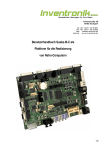
3.1 Configuring the Clock/Calendar
SixPakPius is shipped from the factory with the clock/calendar
enabled. To confirm the default configuration, check that a
shorting plug is instailed at position ClK of the Port Enable
Jumper Block, as sl10wn in Figure 3-1.
3-1
Advanced Configuration
Pin elK-clock/calendar enable
(Install shorting plug to enable clock/calendar.
Remove shorting plug to disable clock/calendar.)
Port enable jumper block
::~::~
Figure 3-1. Clock/Calendar Factory Configuration.
".o...
3.1.1 Disabling the Clock/Calendar
You can disable the Clock/Calendar by removing the shorting
plug from position ClK as shown in Figure 3-1. You might want to
disable the Clock/Calendar to avoid a conflict between the I/O
addresses used by the SixPakPlus clock and other devices
installed in your PC. The SixPakPlus Clock/Calendar uses I/O
addresses 02COh through 02C7h.
Section 3.5 provides further technical information on the
SixPakPlus Clock/Calendar
3.2 Preparing Your PC Boot Disk
Once you've installed your SixPakPlus card, you can prepare
your PC boot disk to automatically initialize the time and date
each time that you boot the system. This subsection tells you how
to prepare your DOS disk to automatically invoke the
Clock/Calendar
3-2
Clock/Calendar
STEP 1
If you have not already done so, copy the ASTCLOCK.COM
program from a SuperPak diskette (version 5.1 or later) to your
PC boot disk.
If you are unsure how to COpy a file, consult your DOS Manual.
STEP 2
If your working DOS diskette already has an AUTOEXEC.BAT file,
you must alter that file to include the ASTCLOCK command. To
see the current contents of your AUTOEXEC file, enter this
command (with AUTOEXEC.BAT in the delault drive):
TYPE AUTOEXEC.BAT < Enter>
Your screen will display the contents of your AUTOEXEC file. Now
you must create a new AUTO EXEC file in wl1ich tile command
ASTCLOCK precedes tl1ese other command(s). Enter tl1is
command sequence:
COPY CON: AUTOEXEC.BAT < Enter>
ASTCLOCK < Enter>
. (otl1er commands)
< Function key F6> < Enter> or < Ctrl-Z > < Enter>
If your working DOS disk l1as no AUTOEXEC file, use tile
sequence above to create one (tile only command in the file will
be ASTCLOCK).
For more information about AUTOEXEC files or the DOS COPY
command, see your DOS Manual.
3-3
Advanced Configuration
NOTE
If you want ASTCLOCK to display the date in
European format (dd/mm/yy) when you boot the
system, substitute the command ASTCLOCK/E
for ASTCLOCK in your AUTO EXEC file.
Specifying the E parameter in the AUTOEXEC file
only changes how ASTCLOCK shows the date
when you boot the system; it does not affect how
DOS or other software displays the date.
STEP 3
Reboot your PC (press the < Ctrl > - < Alt > - < Del> key
sequence).
The ASTCLOCK command will display the time and date on the
screen. If necessary, use the ASTCLOCK /R parameter to set the
TIME and DATE on the SixPakPlus as detailed in Section 3.3.
3.3 Setting the Time and Date
This section tells you how to set the time and dale in the
SixPakPlus clock chip.
NOTE
You must use a version 5.1 (or later) SuperPak
diskette to set the SixPakPlus clock chip.
Once you have copied ASTCLOCK to your PC boot disk, you can
update the Clock/Calendar on the SixPakPlus internal
microprocessor chip. DOS TIME and DATE commands only
update the system's time and date parameters in memory; they
don't permanently update the values stored in the SixPakPlus
clock chip until you execute this procedure:
STEP 1
Boot the system with a disk that contains the ASTCLOCK.COM
program.
3-4
Crock/Calendar
STEP 2
Enter this command:
ASTCLOCK
IR < Enter>
Your PC will then display a message like this (the actual date and
time will be different):
A S T c I 0 c k Version X.xx
(c) Copyrigllt AST Research, Inc.,
1982,1984,1985.
resident clock/calendar
DATE & TIME processors loaded.
Current date is 05/21/87
Current time is 08:07:56.65
NOTE
If you want ASTCLOCK to display the date in
European format (dd/mm/yy) when you enter this
command, type ASTCLOCK/R/E instead of
ASTCLOCK/R. Specifying the IE parameter only
changes how ASTCLOCK shows the date when
you enter this command; it does not affect how
DOS or other software displays the date.
STEP 3
Enter this DOS command:
DATE < Enter>
Your PC will display the current date (the actual date displayed
may be different):
Current date is Thurs 5-21-1987
Enter new date:
Enter the new month, day, and year as follows:
3-5
Advanced Configuration
mm-dd-yy < Enler >
where mm is the one or two-digit month designation, dd
is the day, and yy is the year.
If you do not want to change the date, press < Enler > only.
STEP 4
Enter this DOS command:
TIME < Enler >
Your PC will then display the current time (the actual time
displayed may be different):
Current time is 8: 14: 15.82
Enter new time:
Enter the new hour, minute, and second as follows:
hh:mm:ss < Enler >
where hh is the hour, mm is the minute, and 55 is tile
second. Be sure to use 24-hour format for the hour (that
is, 1:00 PM = 13:00,2:00 PM = 14:00, and so on).
Do not enter ilundredths of a second. If you do not want to
change the time, press < Enler > only.
Hint: For maximum accuracy, type in a time that is 10 to 15
seconds ahead of tile actual lime, Ihen observe a digital
watch, and press < Enter> wilen the seconds reading on
the watch catches up to tile value that you typed in.
STEP 5
Reboot your computer by pressing the < Clrl > - < All> - < Del>
key sequence.
3-6
Clock/Calendar
NOTE
Selecting the ASTCLOCK /R parameter selects
the resident option, which allows you to update
the date and time in bOtil PC memory and tile
SixPakPlus clock chip (you cannot update the
clock chip unless a certain portion of the
ASTCLOCK.COM program is resident).
If you use the ASTCLOCK command without the /R parameter, it
simply initializes the PC's date and time by reading that
information from the SixPakPlus clock chip, and then "goes
away"; no portion of ASTCLOCK remains resident, so you cannot
update the date and time information in the clock chip.
3.4 The Clock/Calendar Battery
The lithium Clock/Calendar battery should last for about a year,
and is easily replaceable. You can purchase replacement
batteries from your AST product dealer (part 108-BR2325).
Compatible substitution batteries can also be purchased from
local camera or department stores. Table 3-1 lists compatible
iithium batteries.
3-7
Advanced Configuration
Table 3-1. Compatible Clock/Calendar Batteries.
Manufacturer
Part Number
AST
Duracell
General Electric
Panasonic
Ray-O-Vac
Sanyo
Varta
Radio Shack
108-BR2325
DL2032
BR2325
BR2325
BR2325
CR2032
CR2032
CR2320H*
*Compared to the other batteries listed in this table, the Radio Shack
battery is .5 mm thinner and rated at 50 mAh less than the other
batteries listed. Its life expectancy is approximately 9 months
(compared to a year for the other batteries).
Because the battery is used only when your PC is not operating,
the actual life of your battery will be determined by how much the
PC is used. The clock chip on your SixPakPlus is powered by the
PC system when your PC is on. The battery is used as backup
power only while your PC is off.
To replace the battery, sliglltly lift the retaining clip with your
finger (or a small screwdriver) and use your t11umb or another
small screwdriver to slide the silver battery sideways out of the
battery socket (Figure 3-2). Do not remove the battery socket
from the board.
3-8
Clock/Calendar
Lift retaining
clip slightly
+--Push battery
out sideways
Push through slots on
battery socket for
easiest removal
Figure 3-2. Removing the SixPakPlus Clock/Calendar
Battery.
Take care not to damage or bend the retaining clip by lifting it too
far. The clip completes an electrical circuit and must make solid
contact with the positive (+) side of the battery. Whenever the
battery is removed, it is a good idea to check the clip in the
bottom of the battery holder. Be sure that it is sticking up high
enough to make good contact with the bottom surface of the
battery. When installing a new battery, make sure it is clean and
dry.
NOTE
If you replace the battery, be sure to use the
procedure described in Section 3.3 to restore the
proper time and date.
3.5 Technical Information
The SixPakPlus Clock/Calendar chip is the RICOH RP5C15, and
uses I/O locations 02COh through 02C7h. For more information,
consult the programming information in the RICOH
RP5COI/RP5C 15 Application Manual. AST Research cannot
provide any information other than what is presented here.
3-9
Advanced Configuration
NOTES
3-10
MEMORY CONFIGURATION
4
This section tells you how to:
•
Install other memory expansion boards in your PC along
with the SixPakPlus (Section 4.1).
•
Install additional memory on your SixPakPlus board
(Section 4.2).
•
Troubleshoot memory problems (Section 4.3).
Section 2 of this manual tells you how to configure your
SixPakPlus board (for starting address, memory size, and parity
error checking enable/disable) before you install it into your PC.
4,1 Installing Multiple Memory Boards into Your
PC
The advanced design of the AST Research SixPakPlus makes it
compatible with most other expansion boards available for the
IBM PC. However, when more U,an one memory expansion board
is installed, you must configure the boards to prevent conflicts
between them.
When you install multiple memory boards, you must first
determine where each board is to reside in the PC's memory
area. You can usually install your SixPakPlus either "above" or
"below" the address space occupied by another board:
•
Section 4.1.1 tells you I,OW to install another memory
board "below" the SixPakPlus.
•
Section 4.1.2 tells you how to install another memory
board "above" the SixPakPlus.
4-1
Advanced Configuration
4.1.1 Installing a Board "Below" the SixPakPlus
To address another memory board "beloW' the SixPakPlus. follow
this procedure:
STEP 1
Configure other board to reside immediately "above" the PC
system board memory: Follow the configuration instructions
supplied with the other board.
STEP 2
Disable any unused memory sockets on the other board: If there
are any unused rows of memory sockets on the other board,
disable them so they won't conflict with the SixPakPius. Refer to
the other board's manual for information on how to disable
unused sockets. If you cannot disable unused memory sockets,
you should address the other board "above" the SixPakPlus (as
described in Section 4.1.2). If the other board has switch settings
for the amount of memory on it, then it will probably automatically
disable any unused memory sockets.
STEP 3
Set the SixPakPlus starting address and memory size: Add the
amount of memory on the other board to the amount of memory
on the PC's system board, and set the SixPakPlus starting
address at this value as shown in Figure 2-2 (Section 2 of tllis
manual). Set the SixPakPlus memory size as shown in Figure 2-3.
STEP 4
PC: Set the PC system board switches for the total amount of
memory in your PC: The total amount of memory includes tile
system board, the SixPakPlus, and the other memory expansion
board.
PC XT, Portable, and 3270 PC: Check that the PC system board
switches are set for the memory installed on the system board
only (do not include the memory on the SixPakPlus or any other
expansion memory board). Unless you have changed the amount
of system board memory, these switch settings should not
change.
4-2
Memory Configuration
NOTE
If you have an IBM Expansion Unit, you must set
the Extender Card switch to reflect the total
amount of memory installed (system memory
plus expansion board memory).
4.1.2 Installing a Board "Above" the SixPakPlus
To address another memory board "above" the SixPakPlus, follow
these steps:
STEP 1
Set the SixPakPlus starting address and memory size: The
SixPakPlus starting address corresponds to the amount of
memory on the PC system board. Set the memory size for the
amount of memory on the SixPakPlus itself (see Figures 2-2 and
2-3).
STEP 2
Set the other board's starting address and memory size: Add the
total memory installed on your PC system board to the amount of
SixPakPlus memory. Follow the instructions supplied with the
other memory board to set its starting address for this total. If
necessary, also configure the other board for the amount of
memory installed on it.
STEP 3
PC: Set the PC system board switches for the total amount of
memory in your PC: The total amount of memory includes the
system board, the SixPakPius, and the other memory expansion
board.
PC XT, Portable PC, and 3270 PC: Check that the PC system
board switches are set for the memory installed on the system
board only (do not include the memory on the SixPakPlus or any
other expansion memory board). Unless you have changed the
amount of system memory, these settings should not change.
4-3
Advanced Configuration
NOTE
If you have an IBM Expansion Unit, you must set
the Extender Card switch to reflect the total
amount of memory installed (system memory
plus expansion board memory).
4.2 Installing Additional Memory on the
SixPakPlus
It is easy to add memory to your SixPakPlus any time; you can
upgrade the SixPakPlus to a maximum 576 kilobytes (KB) of
random access memory (RAM). You may add 64- or 256-KB
RAM chip sets, or a combination of both, to configure the
SixPakPlus board to the amount of memory you need.
Figure 4-1 shows which RAM chip sets and switch settings are
required to configure your SixPakPlus board to the amount of
memory you want.
4-4
Memory Configuration
Bank 0
64
64
256
64
64
256
64
KB
KB
KB
KB
KB
KB
KB
Number of banks installed on SixPakPlus
Total
Bank 1 Bank 2 SW1-4 SWl-5 SW1-6 SixPakPlus RAM
-
64 KB
-
256
64
256
256
KB
KB
KB
KB
-
256 KB
256 KB
OFF
OFF
OFF
OFF
ON
ON
ON
ON
OFF
OFF
ON
ON
OFF
OFF
ON
ON
OFF
ON
OFF
ON
OFF
ON
OFF
ON
o KB
64
128
256
320
384
512
576
KB·
KB
KB
KB
KB
KB
KB
SW1
012345678
tDDDDDDDD
*
SixPakPlus
switch SW1
Factory configuration
Figure 4-1. Memory Configuration.
RAM upgrade kits are available from AST in either 64 KB (Model
No. MP-0009) or 256 KB (Model No. MP-150) sets. If you want to
upgrade the SixPakPlus with your own chips. see the
specifications in Section 4.2.1 for 64 KB RAM chips or Section
4.22 for 256 KB.
4-5
Advanced Configuration
NOTE
You must use chips that meet the specifications
listed in Sections 4.2.1 and 4.2.2. If you install
chips that do not meet these specifications, your
computer may malfunction.
If you wish to use the AST memory upgrade kits, you may skip to
Section 4.2.3 for installation instructions.
4.2.1 64-KB RAM Upgrade Chips
If you want to upgrade the SixPakPlus yourself with 64 KB chips,
use dynamic random access memory (DRAM) chips with these
characteristics:
150 or 200 nanosecond (ns) access time
Pin 1 not used
+5 Volt only
The memory chips listed in Table 4-1 are compatible with the
SixPakPlus and the PC or PC XT system board.
4-6
Memory Configuration
Table 4-1. Compatible 64-KB Memory Chips.
Manufacturer
Part Number
AMD
FUjitsu
Hitachi
Inmos
Intel
Micron Technology
AM9064-15PC, AM9064-20PC
MB8264-15P, MB8264-20P
HM4864P-2
IMS2600P-15
P2164A-15, P2164A-20
MT4264N-2, MT4264N-15,
MT4264N-3, MT4264N-20
M5K4164ANP-15, M5K4164ANP-20
MK4564N-15, MK4564N-20
MCM4164BP15, MCM6665AP15,
MCM6665BP15, MCM6665AP20,
MCM6665BP20
UPD4164C-2, UPD4164C-3
MSM3764-15RS, MSM3764-20RS
TMS4164-15NL, TMS4164-20NL
TMM4164P-3, TMM4164P-4,
TMM4164AP-15, TMM4164AP-20
Mitsubishi
Mostek
Motorola
NEC
OKI
Texas Instruments
Toshiba
4.2.2 256 KB RAM Upgrade Chips
If you want to upgrade the SixPakPlus yourself with 256 KB chips,
use dynamic random access memory (DRAM) chips with these
cllaracteristics:
100,120 or 150 nanosecond (ns) access time
Pin 1 not used
+ 5 Volt only
The memory chips listed in Table 4-2 are compatible willl the
SixPakPlus.
4-7
Advanced Configuration
Table 4-2. Compatible 256 KB Memory Chips.
Manufacturer
Part Number
AT&T
Fujitsu
Hitachi
Mitsubishi
Motorola
NEC
Texas Instruments
Toshiba
WCM41256FX-15
MB81256-15
HM50256P-15
M5M4256P
MCM6256L
D41256C-15
TMS4256-15NL
TMM41256P-15
4.2.3 Installing RAM Chips
Follow this procedure when you add memory to tile SixPakPlus:
STEP 1
Silut off tile power to ti,e PC and remove the SixPakPlus board
from tile PC.
STEP 2
Install eacil additional set of nine 64- or 256-KB memory cilips in
tile next empty bank on tile board. For example (refer to
Figure 4-1) if your SixPakPlus has 64 KB on it now, it ilas memory
in Bank 0 only. If you want add 320 KB to SixPakPlus to bring tile
memory up to 384 KB, you will install one set of 64-KB cilips in
Bank 1 and one set of 256 KB chips in Bank 2.
Install the new chips carefully, and take care not to bend tile legs.
Install tile new cilips so tilat the notched ends face tile same
direction as the otiler memory cilips installed on tile board (see
Figure 4-2). If tile memory cilip is not notched, install it so tilat the
pin 1 indicator (a dot in one corner of tile Cllip) faces toward tile
lower left corner of tile board.
4-8
Memory Configuration
NOTE
Each bank of nine chips must be populated
entirely. Do not intermix 64 KB and 256 KB chips
in the same bank.
STEP 3
Set SixPakPlus DIP switch SW1 for the new total amount of
memory on the board. Figure 4-1 shows you how to set SW1 for
the SixPakPlus memory size.
STEP 4
PC only: Set DIP switch SW2 on the PC system board to the new
total amount of memory installed in the PC (see Figure 2-8). This
step is unnecessary for the PC XT, Portable PC, or 3270 PC.
STEP 5
Reinstall the SixPakPlus into the PC and power it up. Now that
there is more memory in the PC, the powerup diagnostics wili
take longer to run. If all goes weil, the system should operate
normally and show the correct new :otal amount of memory when
you enter the DOS CHKDSK command.
You can aiso run the IBM diagnostic routines (see your IBM PC
Guide to Operations manual).
If you get an error, recheck the installation of the new chips and
the switch settings on both the system board and the SixPakPlus.
If every1hing appears to be correctly installed and configured, and
you still get an error, then proceed to Section 4.3 for help in
troubleshooting the problem.
4-9
Advanced Configuration
p
Notch
64·KB or 256·KB
DRAM chip
Pin 1 Indicator
f.
it'"
~
it
it"
_. " - ". _. ".
"
".
Q ." O(
q,'''
q,'"
q,'"
,
,
,
11
z~
~
~
~
~
~
~
Yl
"
""
."
..
."
,,,
,,,
,,,
""
"
"
"
."
SixPakPlus" ."
."
~
J
."
".
'"
"
.
~.
\
Ie
US'c3lil
Figure 4-2. SixPakPlus Memory Banks.
4.3 Troubleshooting Memory Problems
The most common indication of a memory problem in the PC is a
PARITY CHECK 2 message on powerup. These examples
illustrate the format of error messages you might see.
If you have a PC, an error message might look like this:
4020201
4-10
Memory Configuration
If you have a PC XT, Portable PC, or 3270 PC, an error message
might look like any of these:
4000020201
40000 (S)
40000 (S) 201
?????
(S) 201
Sometimes you can use the error code to isolate the problem to a
specific memory chip.
The first digit of the error message indicates in which 64-KB bank
the error is occurring. The message 4020 or 40000 tells us that
the error is occurring in Bank 4 of the PC. Because the computer
numbers its memory banks beginning witt1 Bank 0, Bank 4 is
actually the fifth bank in the system.
The "20" in the first two examples tell you which chip in the bank
(that is, which bit in the B-bit data byte) is failing. Look at
Figure 4-1 : the fourth chip from the top of each memory bank is
numbered "20".
An error code of "4020" or "40000 20" means that the fourth chip
(the chip numbered "20" in Figure 4-1) from the top of the fourth
memory bank in the PC is failing. If you have a PC with 256 KB
(Banks 0 through 3) installed on its system board, Bank 4 would
be the first bank on the SixPakPlus board. The "201" in the error
message indicates that there is a problem in memory.
Once you determine which chip you believe is causing the
problem, replace it with a spare chip and see if the error is
corrected (you can tell that the error is corrected when you
reboot your PC and it does not display an error message). If no
spare chip is available, try exchanging the suspect chip with
another one in the same bank which is not failing. If the error then
moves to the new socket, you definitely have a bad chip. If the
4-11
Advanced Configuration
error persists at the original socket, yOll may have a problem with
the board; contact YOllr dealer for assistance.
If yOll get an error message sllch as "40000 (S) 201", it tells yOll
that yOll have a memory problem in Bank 4 in YOllr PC; the "(S)"
simply means that the failing chip is somewhere in the system unit
(that is, somewhere in your computer). The best way to isolate
the problem chip is to swap each Cllip in the failing bank with a
good chip and see if the error is corrected.
If yOll get a"????? 201" error message, it tells yOll only that yOll
have a memory problem somewhere in your computer. You can
try to isolate the problem bank by swapping each memory bank
with good memory chips. Once you have determined which
memory bank is failing, you can replace each of the original chips
and reboot your computer each time you replace a chip. An error
message at boot-up then indicates a faulty chip.
If the bit number of the error code does not match any of the
values shown in Figure 4-1, you might have more than one failing
memory chip. This could be due to a malfunctioning board,
incorrect switch settings, multiple bad memory chips, or even
something as simple as a dirty gold edge connector.
If tile failing bank number is higher than the amount of memory
installed in the PC, recheck your system board switch settings.
If you cannot correct the problem, contact your dealer for
assistance.
4-12
SERIAL PORT
5
Your SixPakPlus comes standard with one serial port for
asynchronous communications. You can use the serial port to
connect your PC to a serial printer, modem, or other device which
uses an RS-232C interlace. The SixPakPlus interlace is a DTE
type (Data Terminal Equipment) with a male DB25P connector.
This section includes the following information:
•
Section 5.1 tells you how to reconfigure the serial port:
changing COM1 to COM2, forcing RS-232C inputs true,
and disabling the SixPakPlus serial port.
•
Section 5.2 discusses serial port programming.
•
Section 5.3 gives serial port I/O address assignments and
pinouts.
•
Section 5.4 discusses serial port diagnostic testing.
5,1 Configuring the SixPakPlus Serial Port
You can install up to two serial ports (called COM1 and COM2)
into your PC. The SixPakPlus serial port has been factory
configured to respond as COM1 (which uses IRQ4). You can
confirm this by checking that shorting plugs are installed at these
positions:
•
Position 1 (CM1) on the Port Enable Jumper Block
•
Position 4 on the IRQ Enable Jumper Block
Figure 5-1 illustrates how to configure the SixPakPlus serial port
as COM1 or COM2.
5-1
Advanced Configuration
Port enable jumper block
C'\l .... C'\lw ~
...J
:;: :;: c.. c..:;:
IRQ jumper block
3 4 7
f1 •••••
r:F:i:l
T""
UU...J...JC)U
I!J ••• ••
~
Pin CM2·COM2
Lr~~
IRQ3·COM2
Pin CM1-COMl
(default position)
IRQ4-COMl
(default position)
Figure 5-1. Serial Port Factory Configuration.
5.1.1 Installing Multiple Serial Ports in a PC
If your PC already has another card with a serial port on it
configured to respond as COM1 (such as the PC XT with its
standard serial board), you must change the port on the
SixPakPlus to respond as COM2 as shown in Figure 5-1:
•
Move the Port Enabie Jumper Block shorting plug from
CM1 to CM2.
•
Move the IRQ Enable Jumper Block shorting plug from 4
to 3.
The SixPakPlus serial port will now respond as COM2.
5-2
Serial Port
5.1.2 Configuring the RS-232C Interface Lines
SixPakPlus conforms to the Electronic Industries Association
(EIA) RS-232C communication standard, which describes the
interlace between DTE and Data Communication Equipment
(DCE). That means that all inputs to an AST serial port (with the
exception of Ring Indicator, pin 22) must be connected to a
signal, even if the connected device does not use one or more of
the interlace lines at connector J 1.
NOTE
SixPakPlus does not support the current loop
teletype interlace.
In the default configuration, SixPakPlus expects the connected
device to drive all input signals to its serial ports.
You do not need to change the SixPakPlus default configuration
as long as the connected devices drives these serial inputs: Clear
to Send (CTS), Data Set Ready (DSR) and Data Carrier Detect
(DCD). The device's instructions will tell you if it does not drive
these inputs.
If your serial device does not drive these serial port inputs, you
can configure the SixPakPlus RS-232C jumper block to "force
true" these inputs to the serial port.
The SixPakPlus RS-232C jumper block is divided into three pairs
of jumpers. The first two are labelled DSR for Data Set Ready, the
second two DCD for Data Carrier Detect, and the last two CTS for
Clear to Send. The top jumper of the pair is labelled 1, and it
forces the input true. The bottom jumper of the pair is labelled 2
5-3
Advanced Configuration
and sets the input to normal. To force all of the inputs true, you
would install the shorting plugs on these pins:
DSR Pin 1
DCD Pin 1
CTS Pin 1
Figure 5-2 illustrates how to force one or more of the above
signals to always be in the true state. Move the corresponding
shorting plug on the RS-232C jumper block (the jumper block
near the top of the SixPakPlus board) from the pair of pins
labelled 2 ("normal") to the pair of pins labelled 1 ('1orced true").
For example, to force the DSR input true, move the shorting plug
from position DSR2 to position DSR1.
When you force a signal true, its connection to connector J 1 will
not affect the function of the serial port.
5-4
Serial Port
DSR
r----, 1 jumpers {
2DCD
1jumpers
E!:3 2 -
DSR
DSR
OeD
OeD
CTS
crs
crs
0
jumpers
1..
1··
G::::3
1-
2-
forced true
normal
forced true
normal
forced true
normal
Normal (default): All input
driven by connected device.
~
_.
" -, ".
c=::(}
.,
~
~
>
~
uz
:;
~
&
':
>
.
uJ>
"'
"'
"'
"'
"'
"'
G
G "" G
""
."
."
."
""
G "" G
1} "" @
SixPokPlus" ."
Figure 5-2. Creating a "Forced True" State.
Whether you use the RS-232C jumper block to force certain
inputs true depends on what device you connect to the serial
port.
You might want to leave the shorting plugs in their "normal"
configuration and instead build a special cable for the serial
device. This would be especially convenient if you will be using
different serial devices on the port at different times.
5-5
Advanced Configuration
Appendix B gives general information on building cables. Also
refer to the manual supplied with your serial device for help in
designing cables.
5.1.3 Disabling the Serial Port
You can completely disable the serial port on the SixPakPlus by
removing both of the shorting plugs shown in Figure 5-1 :
•
Remove the shorting plugs from positions CM1 or CM2
on the Port Enable Jumper Block.
•
Remove the shorting plugs from positions 3 or 4 on the
IRQ Enable Jumper Block.
You must disable one serial port if your PC already has two serlai
ports installed; this prevents conflicts between multiple ports. Be
sure to save the shorting plugs for possible future use.
5.2 Programming the Serial Port
The serial port on the SixPakPlus is completely under software
control, and must be initialized for correct baud rate, parity,
number of databits, and number of stopbits before it can be used.
You or your software must initialize the serial port each time you
turn on the computer.
Typically, the DOS MODE command initializes the serial port
(refer to your DOS Manual for a detailed explanation of this
command). A typical MODE command might look like tllis:
MODE COM1 :1200,N,8, 1,P < Enter>
The above command initializes serial port COM1 for 1200 Baud,
no parity, 8 databits, and 1 stopbit. The "P" is optional and tells
DOS that you will be using the port with a serial printer. You can
also use a similar command to establish communication
parameters for serial port COM2.
5-6
Serial Port
Many applications programs (such as word processors)
automatically handle port initialization, making it unnecessary to
use the MODE command. Refer to your software manual; if it
does not mention the MODE command, it is probably safe to
assume that you can omit that step. If you are unsure, it will not
harm anything to go ahead and use the MODE command
anyway.
If you are using the serial port to operate a serial printer, you may
also need to redirect printer output from LPT1 to COMl or COM2.
This is because DOS always assumes that printer output goes to
parallei port LPT1 unless told otherwise. You can use the MODE
command to redirect printer output from a parallel port to a serial
port. For example:
For printer output to COM 1:
MODE LPT1: COM 1: < Enter>
=
For printer output to COM2:
MODE LPT1: = COM2: < Enter>
A redirection command should follow the first MODE command
that sets up the Baud rate. parity, and so forth. Again, it is
possible that your applications program is handling this
redirection automatically. If so, you can eliminate this step as well.
5.3 Serial I/O Address Assignments and Pinouts
The serial port on the SlxPakPlus uses the system I/O addresses
and IRQ interrupt request lines shown in Table 5-1.
Table 5-1. I/O Addresses and IRQ Interrupt Requests.
Port Configuration
I/O Addresses
IRQ Line
COM1
COM2
03F8-03FFh
02F8-02FFh
IRQ4
IRQ3
5-7
Advanced Configuration
Table 5-2 gives the pinouts for the SixPakPlus serial port
connector J1.
Table 5-2. J1 Pinouts.
J1 Pin #
Signal Name
1
2
3
4
5
6
7
8
20
22
Chassis Ground
TX (Transmit Data)
RX (Receive Data)
RTS (Request to Send)
CTS (Clear to Send)
DSR (Dataset Ready)
SG (Signal Ground)
DCD (Carrier Detect)
DTR (Data Terminal Ready)
RI (Ring Indicator)
Direction
-----
Output
Input
Output
Input
Input
... _..
Input
Output
Input*
* Ring Indicator connection is not required
5.4 Serial Port Diagnostic Testing
Whenever there is any question about the operation of the
SlxPakPlus serial port, we recommend that you run tile IBM
diagnostics, preferably the advanced diagnostics supplied with
the IBM Hardware Maintenance Manual.
For proper diagnostics operation, disconnect any device
connected to the SixPakPlus serial port (such as a modem or
serial printer). Also, make sure that the CTS, DSR, and DCD
jumpers (Figure 5-2) are In the normal (not "forced true") setting.
You can use a "wrap plug" on the J1 connector to perform a very
thorough test of the serial port with the advanced diagnostics. To
build this wrap plug, you need a female DB25S connector, such
as a Winchester Electronics PIN 49-1125S. Jumper the connector
pins as follows:
5-6
Serial Port
Pin 2 to Pin 3 (TX to RX)
Pin 4 to Pin 5 & 22 (RTS to CTS & RI)
Pin 20 to Pins 6 & 8 (DTR to DSR & DCD)
These jumpers are shown in Figure 5-3.
~
...... ...
W
14
~~
15 16 17
1i
~ ~ i ~
~
18 19 20 21
22 ?3 24
25
Figure 5-3. Serial Port Loopback Plug Configuration.
When you ready to run the diagnostic program, attach this plug to
the SixPakPlus' J1 connector. Run the diagnostic program and
answer the Advanced Diagnostics loopback plug question with Y.
Certain versions of the IBM diagnostics may fail on the first pass.
You should therefore ignore the results of the first pass if an error
occurs.
5-9
Advanced Configuration
NOTES
5-10
PARALLEL PORT
6
The SixPakPlus comes standard with a parallel port for interfacing
the PC to a parallel printer (such as the Epson FX-85TH ). This port
is completely IBM-compatible with the IBM PC and uses the same
female DB25S connector as an IBM port.
•
Section 6.1 tells you how to configure the parallel port.
•
Section 6.2 discusses parallel port programming.
•
Section 6.3 gives parallel port I/O address assignments
and pinouts.
•
Section 6.4 discusses parallel port diagnostic testing.
•
Section 6.5 tells you how to configure your SixPakPlus to
allow interrupt-driven parallel printer software to operate
correctly.
Section 3 of this manual tells you how to install the parallel port
ribbon cable onto your SixPakPlus board, and how to install the
board and tile parallel port into your PC.
6.1 Configuring the Parallel Port
You can install a maximum of three parallel ports in the IBM PC
(called LPT1, LPT2, and LPT3). The parallel port on the·
SixPakPlus has been configured at the factory to respond as
LPT1 (LPT2 when a display adapter with a built-in parallel port is
present; see Section 6.1.2). You can confirm that the parallel port
is configured as LPTl by checking that a shorting plug is installed
at position LP1 of the Port Enable Jumper Block (see Figure 6-1).
6-1
Advanced Configuration
Port Enable Jumper Block
tr
Pin LPl • LPTl (Default)
Pi" LP2 • LPT2
•• fil· ••
• • l!J • ••
NOTE: When IBM or AST Monochrome Card
is installed, SixPakPlus LPn automatically
responds as LPT2, and SixPakPlus LPT2
automatically responds as LPTJ.
Figure 6-1. Parallel Port Factory Configuration.
6.1.1 Installing Multiple Parallel Ports in a PC
If your PC already has another card with a parallel port on it
configured to respond as LPT1 you must change one of the
boards to respond as LPT2 (this avoids conflicts between the two
ports). Display adapters with a built-in parallel port always
respond as LPT1 and cannot be changed. To reconfigure the
SixPakPlus. move the shorting plug from position LPl to position
LP2 (see Figure 6-1 ). The parallel port on the SixPakPlus will now
respond as LPT2.
6.1.2 Monochrome Adapter Boards
The built·in parallel port on certain display adapter boards (such
as the IBM monochrome display/printer adapter or the AST
Research MonoGraphPlus™ or PreviewI Tl.') always respond as
LPT1 and cannot be changed. If you have such a board in your
PC, the SixPakPlus parallel port will automatically respond as
LPT2 In its factory default configuration. Do not reconfigure the
SixPakPlus to respond as LPT2. If you do reconfigure the
SixPakPlus for LPT2 when a parallel port that always responds as
LPT1 is installed in your PC, the SixPakPlus parallel port will
respond as LPT3.
6-2
Parallel Port
6.1.3 Disabling the Parallel Port
You can disable the SixPakPlus parallel port by removing the
shorting plug shown in Figure 6-1. You can disable the parallel
port to avoid conllicts when you have several parallel adapters
installed in your PC. Save the shorting plug for possible future
use.
6.2 Programming the Parallel Port
The IBM PC always sends printer output to parallel port LPTl
unless specifically toid otherwise. Unfortunately, PC-DOS 1.0 and
1.1 do not allow you to redirect output from one parallei port to
another. Appendix C of this manual tells you how you can cause
the PC to redirect printer output from LPTl to LPT2 or LPT3.
Although it is not required, you can use the DOS MODE
command to set the line width and the number of lines per page.
Refer to your IBM DOS Manual for more information.
6.3 Parallel Port I/O Addresses and Pinouts
The SixPakPlus parallel port uses the PC I/O addresses shown in
Table 6-1.
Table 6-1. Parallel Port I/O Addresses.
Port Configuration
I/O Addresses
LPT1*
LPT2*
0378-037Fh
0278-027Fh
*When you use a display adapter with a built-In parallel port,
the PC sees a SixPakPlus parallel port configured for LPTl
as LPT2, and a SixPakPlus parallel port configured for
LPT2 as LPT3.
6-3
Advanced Configuration
You can use the standard IBM Parallel Printer Cable to connect
the SixPakPlus to an IBM or IBM-compatible printer. You can also
use the information in Table 6-2 to heip build a cable for your
parallel printer.
Table 6-2. Parallel Port Pinouts.
AST Adapter Cable
IBM Matrix Printer
Output
J2 Pin
DB25S
Centronics Interface
Line
Name
-STROBE
DO
D1
D2
D3
D4
05
06
07
-ACK
BUSY
PE
SLCT
-AUTOFD
-ERROR
-iNIT
-SLCT IN
GROUND
1
3
5
7
9
11
13
15
17
19
21
23
25
2
4
6
8
(1!) 12,14,16,
18,2!) 22,24)
1
2
3
4
5
6
7
8
9
11)
11
12
13
14
15
16
17
(18-25)
1
2
3
4
5
6
7
8
9
11)
11
12
13
14
32
31
36
(16,19-3!) 33)
NOTE
A dash in front of the line name denotes lines
which are functionally active when low.
6-4
Parallel Port
6.4 Parallel Port Diagnostic Testing
The parallel port on your SixPakPlus is compatible with the IBM
diagnostics. However, you must configure the parallel port as
LPT1 so that the port can be recognized by the diagnostics.
To run the diagnostics you must provide incoming signals to the
port by installing a wrap plug in the parallel port connector. To
construct a wrap plug connect the foliawing pins on a DB25P
(male) connector. Use 30AWG (minimum) wire to make the
connections.
Pin
Pin
Pin
Pin
Pin
1 to Pin 13
2 to Pin 15
10 to Pin 16
11 to Pin 17
12 to Pin 14
These jumpers are iliustrated in Figure 6-2.
i
1/
3
f(\ •
4
5
6
7
8
9
10
11
1i\.,~
. . . . . . . . . . ,--
,J ~15 16....
i""• • • • • • •
17 18 19 20 21 22 23 24 25
14
Figure 6-2. Parallel Port Loopback Plug
Configuration.
6-5
Advanced Configuration
NOTE
You cannot perform the IBM diagnostics on the
parallel port if you have installed the IBM
Monochrome Display/Printer Adapter.
If you run the matrix printer test, your printer must be 100%
compatible with an Epson MX-80 or errors can be generated.
6.5 Interrupt-Driven Parallel Printer Software
Interrupt-driven parallel printer software uses IRQ? To ensure that
your interrupt-driven parallel printer software operates correctly,
you must enable IRQ? on the SixPakPlus, as shown in Figure 6-3.
It will not harm anything to enable IRQ? even if you do not run
interrupt-driven software for your parallel printer.
IRQ Jumper Block
347
~
~
Figure 6-3. IRQ? Enabled.
6-6
GAME PORT
7
The SixPakPlus game port provides an interface for connecting
one or two joysticks to your PC. With appropriate software, the
joystick can be used for cursor control, as well as graphics
development and interactive games.
This section includes the following:
•
Section 7.1 tells you how to enable or disable the game
port.
•
Section 7.2 discusses software compatibility.
•
Section 7.3 gives the I/O address assignment and pinouts
for the game port.
•
Section 7.4 discusses game port diagnostic testing.
•
Section 7.5 gives you the information you need to
upgrade the SixPakPlus to add the game port.
7.1 Configuring the SixPakPlus Game Port
To enable the game hardware: The game port ribbon cable must
be installed on your SixPakPlus board (as described in Section 2
of this manual), and the proper shorting plug must be installed on
the Port Enable Jumper Block Pin GME, as shown in Figure 7-1.
The game port hardware must be installed on the board (Section
7.5 provides Information on adding the port to your SixPakPlus).
7-1
Advanced Configuration
Port enable jumper block
••• • Iel •
• • • • l!J •
I
Pin GME - Game port enable
(Install shorting plug to enable game port
Remove shorting plug to disable game port.)
Figure 7-1. Game Port Enable/Disable.
To completely disable the SixPakPlus game port: Remove the
jumper shown in Figure 7-1.
7.2 Software Compatibility
The game port is totally software-compatible with the IBM game
adapter. Because joysticks are analog devices, the function of
some software can vary with the joystick used, even though the
game port is functioning properly. To compensate for differences
7-2
Game Port
between joysticks. use software that includes a joystick centering
function.
You can use the program listing in Section 7.4 to test the correct
operation of the SixPakPlus game port.
7.3 Game Port Technical Information
This section provides technical information about the SixPakPlus
game port.
7.3.1 Game Port I/O Address Assignment
The game port uses I/O address 0201 h. This information is for
technical reference only; you do not need to know the I/O
address to use the game port.
7.3.2 Game Port Pinouts
The SixPakPlus game port uses a DB15S (socket or female)
interface connector to enable the connection of up to two
joysticks. Table 7-1 summarizes the game port pinouts.
7-3
Advanced Configuration
Table 7-1. SixPakPlus Game Port Pinouts.
SixPakPlus
J3 Pin No.
Joystick A
1
3
5
7
9
11
13
15
DB15S Pin
Number
1
2
3
4
5
6
7
8
Signal
Name
+5VDC
Button 1
X Axis
Ground
Ground
Y Axis
Button 2
+5VDC
Joystick B
2
4
6
8
10
12
14
9
10
11
12
13
14
15
+5VDC
Button 1
X Axis
Ground
Y Axis
Button 2
+5VDC
You can connect one joystick directly to the DB 15S connector.
To connect two joysticks, you will need a Y-connector adapter
cable. The adapter cable should have one DB15S connector (to
the SixPakPlus) and two DB15P connectors (to the joysticks).
Pins 1 through 8 on the DB15S should connect to one DB15P,
and pins 9 through 15 to the other, as shown in Table 7-1. Consult
your dealer for further information.
7-4
Game Port
7.4 Game Port Diagnostic Testing
You can use the IBM diagnostics to test the SixPakPlus game
adapter port. Because of a problem in tile diagnostic program,
however, the port may not always show up on the listing of
installed devices. You might prefer to use the program below to
test out the port. This program requires the use of BASICA (not
BASIC).
10 DEFINT A-Z:KEY OFF:CLS:STFiIG ON:SCREEN 2
20 PRINT" X1"," Y1"," X2"," Y2"," 51";" 52";" 53"
30 Xl =STICK(O):Yl =STICK(1):X2=STICK(2):Y2= STICK(3)
40 A= STRIG(l):C= STRIG(5):C =STRIG(3):D= STRIG(7)
50 LOCATE 3:PRINT Xl,Yl,X2,Y2,A;B;C;D
60 GOTO 30
Wilen you run the above program, moving tile joystick in the Xplane (left-right) causes a change in the "Xl" readout, while
moving the joystick in the Y-plane (up-down) causes a change In
the "Y1" readout. Pressing tile switcl1 (eitl1er one or two,
depending on your joystick) causes a change in the "S 1" or "S3"
readouts from 0 to -1. Note that, depending on the quality of your
joystick, you may not be able to get a zero reading in the X and Y
planes when running the program. This is normal and no cause
for alarm.
7.5 Adding the Game Port to Your SixPakPlus
AST Research offers an upgrade kit for Held installation of the
SixPakPlus game port. To order the game port upgrade kit: order
model number SPK-OOOG through your AST dealer. The upgrade
kit consists of a 16-pin IC (No. 558CP) and a 20-pin IC (No.
74LS244). To install tile game port, follow tile procedure
described below.
7-5
Advanced Configuration
CAUTION
Be sure the power switch is off and the power
cord is removed from the system unit. Turn off
any other equipment connected to the computer.
Installing any component while the power is on
can permanently damage your computer and its
components.
STEP 1
Remove the PC's system unit cover: Follow the instructions in
STEP 1 and STEP 2 of Section 2.3.
STEP 2
Remove devices attached to the SixPakPlus board: If you have
installed the parallel port, remove the the ribbon cable attached to
the SixPakPlus board. Disconnect any serial device connected to
the serial port.
STEP 3
Remove the SixPakPlus board: Remove the bracket retaining
screw from the bracket securing the SixPakPlus board to the PC
chassis. With a steady, evenly distributed upward tension, remove
the SixPakPlus board from its slot.
STEP 4
Install the game port ICs: Your game port upgrade kit comes with
two ICs: a 16-pin and a 20-pin IC. Each IC is labelled with a notch
or a small dot to identify the bottom left. Insert the ICs as follows.
It is very important that you do not bend any pins when you insert
your ICs.
With the notch (or dot) on the bottom left, insert the 16-pin Ie in
socket U37, as sllown in Figure 7-2.
With the notch (or dot) on the bottom left, insert the 20-pin IC in
socket U38, as shown in Figure 7-2.
7-6
Game Port
U37: Install 16-pin IC
(No. 558CP) here.
U38: Install 20-pin IC
(No. 74LS244) here.
~
\
pOint(~ndicator
Notch
away from bracket
(if present)
in lower left corner
Figure 7-2. Installing the Game Adapter Port ICs.
7-7
Advanced Configuration
NOTE
If the IC seems too wide to allow the pins to
properly line up witl1 their socket receptacles,
place the IC on its side on a flat surface and
gently angle it under both thumbs to slightly
bend the pins inward. You may find this same
technique useful when actually inserting the IC
into the socket on the board. Angle the IC, and
slightly insert one row of pins, then bring the
other row down into position and slightly start its
pins in the socket. Once you have both sides
started, you can evenly depress the entire IC until
it is firmly seated.
STEP 5
Enable the game port: Make sure the sllorting plug is installed
across Pin GME of the port enable jumper block, as shown in
Figure 7-1.
STEP 6
Replace the SixPakPlus Board: Follow the instructions in
Section 2.4. Make sure to plug the game port connector onto
connector J3, as described in STEP 1 of Section 2.4.
STEP 7
Configure the game port: Follow the instructions in Section 7.1.
7-8
PART III. APPENDICES
A. Troubleshooting and Repair Procedure
B. Serial Interface
C. Switching Between Parallel Ports
D. Installing SixPakPlus in the Older 64-KB IBM PC
NOTES
TROUBLESHOOTING AND
REPAIR PROCEDURE
A
This section outlines some simple procedures for troubleshooting
when you have a problem with your SixPakPlus. It also describes
the procedure for returning your SixPakPlus to the factory should
it require repairs.
A.1 Troubleshooting
The following outlines some suggestions for solving common
difficulties with the SixPakPlus.
PROBLEM: Power-up Self Test fails.
ACTION: A parity error or interrupt conflict can prevent the self
test from successfully completing. To determine the area of
difficulty, disable all features on the SixPakPlus by removing the
appropriate jumpers plugs on the port enable jumper block (refer
to Figure 2-2). Then enable each feature one by one, rerunning
the self test each time, until you isolate the problem area.
PROBLEM: Parallel port doesn't work.
ACTION: Check the following:
•
Check that the device connected to the port works and is
powered on.
•
Check cabling: Check cables between the parallel port
and peripheral device; check that the ribbon cable to the
parallel port connector is securely attached to the
SixPakPlus board.
•
Check that the software you are using is sending output
to the correct device. SixPakPlus is usually configured so
that the parallel port appears as LPT1. Go over the
A-1
Appendices
procedures in Section 6 to make certain the port is
configured as you indented. Check your software to see
to which device it is sending output.
•
Make sure the parallel port is enabled. Check that the
shorting plug shown in Figure 6-1 is installed (Section
6.1.3).
•
Check that IRQ? is enabled (Section 6.5).
PROBLEM: Serial Port doesn't work.
ACTION: Check the following:
A-2
•
Check that the device connected to the serial port is
powered on and working.
•
Check cabling: check cabling between the serial port and
the peripheral device (see Appendix B).
•
Check that the software you are using is sending output
to the correct device. The SixPakPlus is usually
configured so that the serial port appears as COM 1. The
port expects the connected device to drive all serial
inputs. Go over the procedures in Section 5.1 to make
certain the port is configured as you expect. Check your
software to see to which device it is sending output. If
you are using a serial printer, you may need to direct
printer output from LPT1 to COM1 or COM2 (see Section
5.2).
•
Check the jumper positions on the Port Enable Jumper
Block, and the IRQ Jumper Block (Section 5.1).
•
Make certain the serial port is correctly initialized (Section
5.2). Check that the Baud rate, parity, number of data
bits, and number of stop bits for the peripheral device
match what you specified in your DOS MODE command,
or what your software specified for you.
Troubleshooting
PROBLEM: Game port doesn't work.
ACTION: Check the following:
•
Check that the device connected to the game port is
powered on and working.
•
Check cabling: check cabling between the game port
and the peripheral device; check that the ribbon cable to
the game port connector is securely attached to the
SixPakPlus board.
•
Make certain the game port is installed and enabled.
Section 7.1 describes the jumper plug that should be
installed. ICs should be installed in sockets U37 and U38
(Section 7.5).
PROBLEM: Memory errors.
ACTION: Check the following:
•
Check settings on SixPakPlus switch SW1 (Section 2.2).
•
Check settings on PC system boards (Section 2.3).
•
Perform procedures outlined in Section 4.3.
PROBLEM: DOS or ASTCLOCK displays incorrect time or date.
ACTION: Do the following:
•
Set the correct time and date as described in Section 3.3.
•
Replace the clock-calendar battery (Section 3.4), then
reset the clock (Section 3.3).
A-3
Appendices
A.2 Product Repair Procedure
If your AST Research product ever requires repair. contact your
dealer first. The dealer from whom you originally purchased the
product can usually service the product. If you must return a
hardware product to the factory for service. follow these
guidelines to ensure rapid, accurate turnaround:
1.
Call AST Research Technical Support for a Return
Authorization Number (RAN): A technician will discuss
the problem with you; if factory service is required. the
technician will give you a Return Authorization Number
(RAN). Always refer to the RAN when you return anything
for service. AST Research will return anything without a
RAN to the sender.
2.
If the product is covered under an AST Research
warranty: There is no charge for parts or labor involved in
the repair. Please include a copy of your original
purchase receipt as the proof of date of purchase for all
warranty repairs.
If the product is not covered under an AST Research
warranty: Contact your dealer or AST Research Technical
Support for further information.
3.
Parts not covered under the warranty: Dealer- or userinstalled parts (such as RAM chips) are not covered
under the terms of the warranty. Dealer-installed parts are
warranted by the dealer; parts that you install are covered
only by the parts suppliers' warranties. If we find that your
dealer or user-installed parts are defective. we can
identify which parts are defective. but we will not replace
parts unless you specifically authorize us to do so in
writing when you send the board to us. The parts charges
and any applicable labor charges will be billed COD.
4.
Describe the problem and return any related
accessories: Please include a brief but explicit written
description of the problem when you return your AST
A-4
Troubleshooting
product to the factory for repair. Also return any
accessories that might relate to the problem. For
example, if the the parallel port does not function
correctly, be sure to return the parallel port adapter cable
with the board.
5.
Be sure to provide a return shipping address that UPS
can deliver to and include your RAN: UPS cannot
normally deliver to post office boxes. Reference the RAN
issued to you by AST Technical Support on all
correspondence. Securely package all materials to
prevent shipping damage. Shipping charges must be
prepaid; COOs will not be accepted. Ship the materials to
the following address:
AST Research, Inc.
Customer Service RAN xxxx
2722 Michelson Drive
Irvine, CA 92715
wllere xxxx is your assigned Return Authorization
Number.
6.
Once your product is repaired, we will return it to you by
UPS or UPS Biue Label service, whichever is appropriate
for your geographicai location. We will return items
covered by warranty at our expense. Shipping costs
and repair expenses for items not covered by warranty
will be billed COD. If you prefer overnight service (UPS
Red Label), the shipping charges will be billed COD. If
you want us to ship Federal Express, piease give us your
Federal Express account number for billing purposes.
A-5
Appendices
NOTES
A-6
SERIAL INTERFACES
B
This appendix provides general information on wiring the
SixPakPlus serial port to other serial devices (such as printers,
plotters, or modems). including:
•
The RS-232C serial interface standard (Section B.1).
•
Interfacing DTE to DCE (Section B.2).
•
Interfacing DTE to DTE -- "null modem" (Section B.3).
•
Designing your own serial interface (Section BA).
The SixPakPlus serial port is completely IBM-compatible. In most
cases, you can connect your remote device to the SixPakPlus
serial port with a cable provided with the device itself. Simply refer
to the instructions proVided with the device or will1 the software
for driving it.
In some cases, your instructions will specify how your remote
device uses RS-232C line signals and which pin numbers supply
which signals. With this information, plus the information in this
appendix, you can construct an interface cable yourself.
NOTE
Serial devices use RS-232C signals in different
ways. AST Research cannot tell you how to
connect a particular device to your serial port.
You must refer to the manufacturer's instructions
that came with that device.
The SixPakPlus serial port does not support the
current loop teletype interface.
B-1
Appendices
B.1 RS-232C Interface Standard
SixPakPlus connects to other serial devices according to the
Electronic Industry Association (EIA) RS-232C interlace standard.
The RS-232C standard describes the sequence of signals that
travel between two serial devices. The signals control the
exchange of data between serial devices. RS-232C defines 20
signals (although few applications use all 20), and each signal
travels separately on a predefined wire.
The RS-232C standard classifies communications devices as:
•
Data terminal equipment (DTE): Equipment associated
with the user, such as a PC or a mainframe computer.
The SixPakPlus serial port is a DTE device.
•
Data communications equipment (DeE): Equipment
associated with transmission facilities, such as a modem.
The RS-232C standard describes the ideal case. where a DTE
device connects to a DCE device. Before sending data, the
SixPakPlus serial port must send and receive RS-232C signals in
this order:
B-2
1.
Some DCE devices use the Ring Indicator (RI) signal to
alert SixPakPlus that incoming data is due.
2.
SixPakPlus sends Data Terminal Ready (DTR) to signal a
request for a communications link.
3.
SixPakPlus receives Data Carrier Detect (DCD) and Data
Set Ready (DSR) -- these signals indicate that the DCE is
ready.
4.
SixPakPlus sends Ready To Send (RTS) -- this signal tells
the DCE that SixPakPlus is ready to send data.
5.
SixPakPlus receives Clear To Send (CTS) -- a signal from
the DCE to go ahead and transmit data.
Serial Interlaces
6.
SixPakPlus then starts transmitting data via the Transfer
Data (TxD) signal. SixPakPIus receives data via the
Receive Data (RxD) signal.
To prevent damage to either device, the chassis ground and
signal ground signals must always be connected. For the
SixPakPlus seriai port, connecting to pin 1 or pin 7 or both makes
the connection to chassis ground and signal ground.
You can think of certain pins on one side of the interface as
"functional pairs":
DTE
DCE
DTR--------------------------DSR and DCD
RTS -------------------------- CTS
TxD --------------------------RxD
B.2 Interfacing DTE to DeE
An example of a DTE-to-DCE interface that conforms to the RS232C standard would be to connect the SixPakPlus serial port
(DTE) to a telephone modem (DCE). A correctly configured
DCE/DTE interface is wired straight across: DTE pin 20 wired to
DCE pin 20, pin 2 to pin 2, and so forth.
Two serial devices interact in a certain sequence -called
"handshaking" -to function properly:
1.
Some modems (DCE) have an automatic answer mode
that uses the signal RI to alert the DTE that incoming data
is due. SixPakPlus (the DTE) would then use DTR to
respond to RI.
2.
When the SixPakPlus serial port (DTE) wants to send or
receive data it raises the voltage on pin 20; pin 20 carries
the DTR signal. This voltage travels to DCE pin 20 where
the modern interprets it to mean that a communications
link is being requested by the DTE device.
B-3
Appendices
3.
If an open phone line exist~, the DCE brings up two lines
on its side of the interface: DSR and DCD.
4.
When the DTE sees high voltage at its pins 6 and 8, it can
then bring up pin 4, RTS. RTS tells the DCE that the DTE
has data to transmit to it.
5.
The DCE checks that it is ready to receive data; if so, it
brings up pin 5, CTS.
6.
Once the DTE sees voltage on its pin 5, it can transmit
data on the wire connected to pin 2, TxD -or it can
receive data via RxD.
CAUTION
To help protect your equipment from damage, be
sure to connect the ground wires (pins 1 and/or
7).
Figure B-1 shows an ideal DTE-to-DCE interface, inciuding
signals, signal directions, and sequence (top to bottom). The
interface must handle these signals before the DTE can transmit
or receive data:
8-4
•
DCD, DSR, CTS, and RxD are input signals to the
SixPakPlus.
•
DTR and RTS are output signals from the SixPakPlus.
Serial Interfaces
OlE
DCE
Pin #
Pin #
Signal
Chassis
Ground
Signal
Ground
(RI)
22
DTR
20
20
DTR
DCD
8
8
DCD
DSR
6
6
DSR
RTS
4
4
RTS
CTS
5
5
CTS
TxD
2
2
TxD
RxD
3
3
Rxd
7
7
+---------------
22
Signal
Chassis
Ground
Signal
Ground
(RI)
Figure 8-1. DlE-Ia-DCE Inlerface.
Figure B-1 silows the interface signals in order of occurrence (top
to bottom). From the DlE"s standpoint, it must send DTR, see
DCD, see DSR, send RTS, and see CTS before transmitting or
receiving data.
The DTE inputs must have voltage applied to them for tile
interface to become operational (the DTE outputs are necessary
only because tiley are inputs to the DCE side of the interface).
The DTE hardware does not release data to the communications
link until il has received the proper set and sequence of signals.
8-5
Appendices
B.3 Interfacing DTE to DTE ("Null Modem")
Many devices (such as serial printers) are set up as DTE. To
output data from the SixPakPlus serial port (also DTE) to another
DTE serial device. you must wire a DTE to DTE (or "null mOdem")
interlace. A DTE-to-DTE interlace is also called a null modem
connection because it does not include a DCE device such as a
modem. Other examples of null modem connections include
connecting two PCs, or connecting a PC to a mainframe.
A null modem interlace must provide "response" inputs to either
side of the interlace -- just as if a DCE device were present. The
input voltages to each DTE device must occur in the correct
sequence (the correct sequence varies from device to device).
Each side of a null modem interlace acts like the DTE side of a
DTE-to-DCE interlace. Both sides of the null modem interlace
must send and receive these signals in this sequence before
sending or receiving data:
Send DTR
Receive DCD and DSR
Send RTS
Receive CTS
Figure B-2 shows a standard null modem configuration, including
signal directions and sequence.
B-6
Serial Interfaces
Other
Serial Port
SixPakPlus
Serial Port
Signal
Pin #
Pin #
DTE
DeE
Signal
Ground
Ground
7
7
Ground
DTR
20
20
DTR
DCD
8
8
DCD
DSR
6
6
DSR
RTS
4
4
RTS
CTS
5
5
CTS
2
TxD
3
RxD
Ground
TxD
RxD
2
3
U
I
I
I
I
Figure B-2. Example #1: Null Modem (DTE-to-DTE)
Interface.
B-7
Appendices
Figure B-3 illustrates another null modem interface, including the
direction and sequence of the signals.
Example
Printer
SixPakPlus
Serial Port
Signal
Pin #
Pin #
DTE
DeE
Ground
Ground
Ground
Signal
7
7
Ground
DTR
20
20
DTR
DCD
8
8
DCD
DSR
6
6
DSR
RTS
4 f--
4
RTS
CTS
5
5
CTS
TxD
2 t--
2
TxD
RxD
3
3
RxD
I
I
I
I
Figure B-3. Example #2: Null Modem Interface.
Notice that the necessary input signals are supplied to both sides.
DCD, DSR, and CTS have voltage applied to them on either side.
The example shown in Figure B-3 changes the ideal sequence by
having the printer DTR signal drive PC signal CTS. The chip that
B-8
Serial Interfaces
controls the SixPakPlus serial port (an 8250 UART chip) is fairly
flexible in reading the sequence of inputs.
The input sequence in Figure 8-3 is changed because the printer
in the example drops its DTR signal when its receive buffer is
about to fill up. To avoid losing data when the printer's receive
buffer overflows, the interface halts PC data output immediately
by dropping the CTS input to the PC side immediately. The
remainder of the interface then "idles" until the printer raises DTR
again. Remember that this is a specific case for this particular
printer.
Figure 8-4 shows another example of how to interface a serial
printer to a SixPakPlus serial port.
8-9
Appendices
SixPakPlus
Serial Port
Signal
Other
Serial Port
Pin #
Pin #
DTE
DeE
Ground
Ground
Signal
Ground
7
7
Ground
DTR
20
20
DTR
DCD
8
a
DCD
DSR
6
6
DSR
RTS
d
19
SRTS
CTS
5
5
CTS
TxD
2
2
TxD
RxD
3
3
RxD
I
W
I
~
I
r
-
Figure 8-4. Example #3: Null Modem Interface.
In Ihis case. the printer uses SRTS (Secondary Request to Send,
pin 19) instead of pin 4 (RTS); apart from that exception, Figure
8-3 follows the ideal DTE input and sequence rules.
The advantage of the interface shown in Figure 6-4 is that every
pin is driven by its functional counterpart on the other side of the
interface; the functionally related signal pairs include DTR/DSR,
RTS/CTS, and TxD/RxD. This should aiso hold true for the
interface you design.
8-10
Serial Interfaces
8.4 Design Aids
Your serial device manual tells you how the device uses the
RS-232C line signals and which pin numbers supply which
signals. You can also contact the device manufacturer for further
information on interlacing to an IBM PC asynchronous serial port.
Serial ports on all AST Research boards are IBM-compatible.
Your dealer can direct you to a parts store that carries the
products you need to construct an interlace cable. You must use
the correct type of 25-pin connectors (male or female) to connect
both ends properly. The SixPakPlus serial port end plugs into a
DB25S (female/socket type) connector.
To wire your serial interlace signals properly, we suggest you use
the form shown in Figure B-5 as a design aid.
B-ll
Appendices
AST Serial Port
IBM PC Side
Signal
Pin #
Serial Peripheral
Device
Pin #
Ground
Ground
Signal
1
Ground
7 Ground
7
Output
DTR 20
Input
DCD
8
I-
Input
DSR
6
I-
Output
RTS
4
Input
CTS
5
Data Out
TxD
2
Data In
RxD
3
I-
t-
Figure B-5. Seriallnlerlace Form.
II you plan to use several different serial devices on your serial
port, you can make a separate interface assembly for each,
device. That way you can use the same long cable to connect
your PC to any 01 these devices.
B-12
SWITCHING BETWEEN PARALLEL
PRINTER PORTS
C
This appendix gives you programs you can use in a batch file to
direct printer output normally designated for the device attached
to port LPT1, to instead be routed to the device attached to port
LPT2 or LPT3. (The program also directs output, normally
designated for the device attached to port LPT2 or LPT3, to
instead be routed to the device attached to port LPT1.) For more
information on creating a batch file, see your IBM DOS Manual.
The programs in this appendix are particularly useful if your
applications program (a word processing program, for example)
is capable of sending print output to only one parallel port. You
might also use this program when your LPT1 printer (call it printer
# 1) is down for service, or when you want to take advantage of
the type style or speed of the printer attached to LPT2 or LPT3
(call it printer #2 or #3). This program allows you to quickly
switch between outputs without having to alter your hardware
interface or change each line in programs where LPT1, LPT2, or
LPT3 appear as your output port designation.
If your printers are not configured to the same parameters, as
defined in the DOS MODE command, you must add two MODE
statements when switching devices.
Notice that the "swap" program below is written in BASIC. Since
the printer port swap is best handled in DOS, BASIC is invoked
within the .BAT file. No RUN command is required when the
BASIC call and the program file name occur on the same line
(BASIC LPTSWAP). Consult your IBM BASIC Manual if you have
any questions about entering and saving the LPTSWAP.BAS
program.
C-1
Appendices
C.1 Switching Between LPT1 and LPT2
The following DOS batch file and BASIC program redirects printer
output from LPTl to LPT2 or vice versa, depending on whicll port
is being used at the time.
LPTSWAP.BAT (or a name of your choosing) witllthe following:
MODE LPT1:[parameters for printer #2 (if needed))
MODE LPT2:[parameters for printer #1 (if needed))
BASIC LPTSWAP
LPTSWAP is a BASIC program, as shown below. The comments
are included for clarification and need not be included in the
actual program.
10 DEF
SEG~&H40
, finds port address table
, save LPTl address
20 A= PEEK (8): B= PEEK (9)
30 POKE 8.PEEK (10): POKE 9,PEEK (11)
. LPT2 address to LPTl
40 POKE 10.A: POKE ",B
, LPT 1 address to LPT2
50 SYSTEM
, return to DOS
Omit statement 50 if you will be LPRINTing from BASIC.
C.2 Restoring LPn to LPn and LPT2 to LPT2
Use the same program, LPTSWAP, to restore your parallel printer
ports to their original arrangement Be sure to restore the proper
parameters using a new batch file and MODE statements.
LPTRSTR.BAT is as follows:
MODE LPT1:[paramelers for printer #1 (if needed))
MODE LPT2:[paramelers for printer #2 (if needed)]
BASIC LPTSWAP
C-2
Switching Between Parallel Ports
C.3 Switching Between LPn and LPT3
The following DOS batch file and BASIC program redirects printer
output from LPT1 to LPT3 or vice versa, depending on which port
is being used at ti,e time.
LPTSWAP.BAT (or a name of your choosing) with the following:
MODE LPT1 :[parameters for printer #3 (if needed)]
MODE LPT3:[parameters for printer #1 (if needed)]
BASIC LPTSWAP
LPTSWAP is a BASIC program, as shown below. The comments
are included for clarification and need not be included in the
actual program:
10 DEF SEG = &H40
, finds port address table
20A=PEEK (8): B=PEEK (9)
'save LPTl address
30 POKE 8,PEEK (12): POKE 9,PEEK (13)
'LPT3 address to LPTl
40 POKE 12,A: POKE 13.B
. LPT1 address to LPT3
so SYSTEM
, return to DOS
Omit statement 50 if you will be LPRINTing from BASIC.
C.4 Restoring LPT1 to LPn and LPT3 to LPT3
Use the same program. LPTSWAP, to restore your parallel printer
ports to their original arrangement. Be sure to restore the proper
parameters using a new batch file and MODE statements.
LPTRSTR.BAT is as follows:
MODE LPT1:[parameters for printer #1 (if needed)]
MODE LPT3:[parameters for printer #3 (if needed)]
BASIC LPTSWAP
C-3
Appendices
NOTES
C-4
INSTALLING SIXPAKPLUS IN THE
OLDER 64-KB IBM PC
D
This appendix provides instructions for configuring and instailing
SixPakPlus if you have an original (64 kilobyte (KB) system board)
IBM PC.
Definition: The original PC has 64 KB of memory on its system
board. The system board switches on the 64-KB PC can be set for
a maximum of 544 KB. However, it is possible to install up to 640
KB in the 64-KB PC; you must install the IBM BIOS ROM Upgrade
Kit (IBM PIN lS01005) to enable a full 640 KB to be recognized.
Configuration and installation: Follow this procedure to configure
and install SixPakPlus in the older PC:
STEP 1
Configure SixPakPlus for the starting address (64 KB), the
amount of SixPakPlus memory, and parity check enableldisable.
Section 2 tells you how to configure the SixPakPlus.
The only special instruction for the 64-KB PC is that the
SixPakPlus starting address is always 64 KB (unless another
memory expansion board is installed starting at 64 KB). If another
memory board is installed starting at 64 KB, set the SixPakPlus
starting address at the end of installed memory.
STEP 2
Open the PC. Section 2 (as well as the IBM PC Guide to
Operations) tells you how to open the PC. The procedure for
opening the original PC is the same as for the latter (256-KB
system board) PC.
STEP 3
Set the PC system board switches for the total amount of
memory and the number of disk drives (if you are adding
SuperDrive). Set switch SW2 (shown in Figure D-1) on the system
D-1
Appendices
board for the total amount of memory in the PC (including system
memory and all expansion memory).
Total Memory
64
128
192
256
320
384
448
512
544
SW2-1
SW2-2
SW2·3
SW2-4
ON
ON
ON
ON
ON
ON
ON
ON
OFF
ON
OFF
ON
OFF
ON
OFF
ON
OFF
OFF
ON
ON
OFF
OFF
ON
ON
OFF
OFF
OFF
ON
ON
ON
ON
OFF
OFF
OFF
OFF
OFF
KB
KB
KB
KB
KB
KB
KB
KB
KB
'--
./
V'
SW2
o
1
2
3
4
5
6
7
8
tDDDDDDDD
Figure 0-1. Switch Setting SW2 for Total Memory in
the PC.
Some applications programs available for the PC do not work
correctly when the switches are set for 544 KB. You should
therefore use the 512-KB selling even if you Ilave more than 512
KB installed in your 64-KB PC. SuperOrive and SuperS pool (as
well as certain other programs) can still use the excess beyond
the 512-KB selling.
If your original PC is equipped with the IBM Expansion Unit and
has the new read-only memory basic input output system (ROM
BIOS) installed, you can address a full 640 KB, and you should
use the switch settings for the laller (256-KB) PC (see Section 2).
Set SW-l (Figure 0-2) on the system board for tile number of disk
drives (including floppy and SuperOrives).
0-2
Installing SixPakPlus in a 64-KB IBM PC
Number
of Drives
System Board
Switch SW1
Floppy/SuperDrive
IBM
Fixed Disk
Designations
Designation
012345678
t~DDDDD~~
A:
C:
A:S:
C:
t~DDDDD~~
A:S:C:
D:
012345678
A:S:C:D:
E:
012345678
2
t~DDDDDD~
012345678
3
4
t~DDDDDD~
Figure 0-2. Switch Setting SW1 for Number of Disk
Drives (If Installing SuperDrive).
STEP 4
Install the SixPakPlus board in your PC. The procedure for
installing SixPakPlus in the older 64-KB PC is the same as for the
later (256-KB system board) PC.
Troubleshooting Memory Problems: The troubleshooting
procedure for memory problems (described in Section 4.3) is the
same for the 64-KB PC as for other PCs.
0-3
Appendices
The only special point to remember is that the first 64-KB memory
bank (Bank 0) in your PC will always be system memory. All other
memory banks will then refer to expansion memory.
For example, if you have a 64-KB PC that includes a SixPakPlus
with 384 KB of memory:
Bank 0 is on the system board.
Banks 1 through 6 are on the SixPakPlus.
An error message like "3020201" would point to the fourth bank in
an 64-KB PC. Bank 0 is on the system board. Banks 1 and above
are on the SixPakPlus. The fourth bank in the PC is the third bank
on the SixPakPlus.
0-4
LIMITED WARRANTY
AST Research, Inc. warrants to the original purchaser of this AST
Research, Inc. product that it is to be in good working order for
a period of 2 years from the date of purchase from AST Research,
Inc. or an authorized AST Research, Inc. dealer. Should this
product, in AST Research, Inc.'s opinion, malfunction during the
\\Oarranty period, AST will, at its option, repair or replace it at no
charge, provided that the product has not been subjected to misuse,
abuse, or non-AST authorized alterations, modifications, and/or
repairs.
Products requiring Limited Warranty service during the walTanty
period should be delivered to AST with proof of purchase. If the
delivery is
by
mail, you agree to insure the product or assume risk
of loss or damage in transit. You also agree to prepay shipping
charges to AST.
ALL EXPRESS AND IMPLIED WARRA TIES FOR THIS
PRODUCT INCLUDING, BUT NOT LIMITED TO, THE
WARRANTIES OF MERCHANTABILITY AND FITNESS FOR A
PARTICULAR PURPOSE ARE LIMITED IN DURATION TO THE
ABOVE 2 YEAR PERIOD. Some states do not allow limitations on
how long an implied warranty lasts, so the above limitations may
not apply to you.
UI DER NO CIRCUMSTANCES WILL AST RESEARCH, INC.
BE LIABLE IN ANY WAY TO THE USER FOR DAMAGES,
INCLUDING ANY LOST PROFITS, LOST SAVINGS OR OTHER
INCIDENTAL OR CONSEQUENTIAL DAMAGES ARISING OUT
OF THE USE OF, OR I ABILITY TO USE, SUCH PRODUCT.
Some stales do not allo\\' the exclusion or limitation of incidental
or consequential dal11clges for consumer products, so the above limitations or exclusion IllclY not clpply to YOll.
THIS WARRANTY GIVES YOU SPECIFIC LEGAL RIGHTS, AND
YOU MAY ALSO HAVE OTHER RIGHTS WHICH MAY VARY
FROM STATE TO STATE.
The limited warranty <lpplies to htlrdware products only.
AST RESEARCH, INC.
Product Comment Form
SixPakPlus@
User's Manual
000490-001 A
We appreciate your comments regarding any problems or
suggestions related to AST Research products. Please use
this form to communicate any observations that you have
concerning the improvement of either the product itself or
the product documentation provided in this manual.
Submitter Information
Submitter's name:
Address:
Product/Manual Comments and Suggestions
Please mail this form to:
AST Research, Inc.
Attn: Product Marketing
2121 Alton Ave.
Irvine. CA 92714-4992