1
49
Small Vision System User Manual
6.
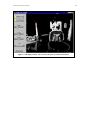
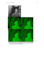
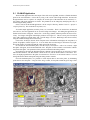
Detect the corner features in all views by pressing the features button in the lower bar of
buttons. This cycles through all the images, displaying the corners in green as they are detected.
If the feature finder fails on an image, please re-capture the image and redetect the features. When
redetecting features for a single stereo pair, use the features button in the stereo pair box.
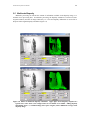
7. Compute the calibration parameters (intrinsics, extrinsics) and rectification matrices by pressing
the calibrate button in the lower button bar. This operates in three phases:
a) Calibrates individual views using a planar model of the calibration object. The projection of
these model features is shown in red.
b) Calibrates all the views jointly using nonlinear optimization over all the intrinsic and extrinsic
parameters. This phase usually takes a few minutes, and when finished, the projected model
features are shown in yellow.
c) Computes the rectification matrices from the joint calibration in (b).
8. When the calibration is finished, you have additional options in the lower button bar: save
writes the parameter file to disk and send transfers the new parameters to the main smallvcal
window. Done exits from the calibration dialog.
4.1.2
Calibration Target
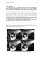
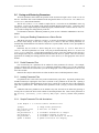
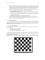
To get the best possible calibration, we recommend using the largest possible calibration target, with
squares at least 100 mm on a side (check4.pdf). These targets can be printed at a copy shop, and pasted
to foam-core posterboard. You can use your own custom target, with squares of any size, but it must have
the same number of squares as the Videre target.
4.1.3
Imager Characteristics
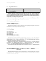
The calibration process must be related to the geometry of the camera imagers. There are three
important parameters:
1. Pixel size in mm (width and height)
2. The width of the imager in pixels
3. The width of the image output by the framegrabber
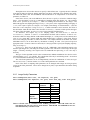
The stereo rigs from Videre Design (DCS series, MEGA-D, Daul-DCAM) have preset values; just use
the appropriate button in the Calibrate dialog. Otherwise, select the Custom value, and choose values
according to the instructions below.
The pixel size can be found from the specifications of the imager. If you cannot find these, just use
defaults of 0.010 mm. The calibration will determine the pixel aspect ratio (width / height). The calibrated
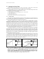
Figure 4-1 Checkerboard calibration object.