1
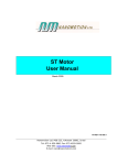
OPERATION MANUAL
SERIES 123000
BORESCOPES
INSTRUMENT
TECHNOLOGY, INC.
POB 381, Westfield, MA 01086
33 Airport Road, Westfield, MA 01085
Tel: (413) 562-3606
Fax: (413) 568-9809
Email: [email protected]
www.scopes.com
INTRODUCTION
Thank you for selecting Instrument Technology, Inc. (ITI) to fulfill your remote viewing needs.
Since 1967, ITI has been the Leader in Remote Viewing. The only company of its type doing all its manufacturing
in the United States, ITI consistently provides cutting edge technology to customers world-wide.
ITI specializes in the design, development and manufacture of Remote Viewing Instruments (RVI) and systems
including Borescopes, Fiberscopes and Videoscopes.
ITI offers over 2,000 standard products as well as products custom designed for unique applications. No matter
which ITI product is used, our customers find they are able to observe hostile and difficult to reach environments
never dreamed possible before. Though ITI products can solve many remote viewing problems, it is always best
to select the proper instrument for any given application. Only then can success be assured.
Your satisfaction is guaranteed with all products purchased from Instrument Technology, Inc. Feel free to contact
ITI or your local ITI Representative with any questions.
WARRANTY
Instrument Technology, Inc. warrants that the equipment is fit for the purposes described herein for a period of
one year after the date of shipment when used in accordance with the directions for use, and agrees to repair or
replace any such defective component part at no cost to the customer.
There are no other express or implied warranties. ITI's sole obligation and purchaser's exclusive remedy for
breach of any warranty shall be limited to repair or replacement of the product at the option of ITI. This warranty
does not cover, and ITI will not be liable for any resulting direct, proximate, incidental or consequential damages.
This warranty does not apply if the product has been subject to misuse, negligence, accident or improper
application, nor shall ITI be responsible for work done or repairs made by others.
PRODUCT SPECIFICATIONS
The following chart summarizes ITI’s Series 12300 Borescope Line, representing over 800 combinations.
Model
!
Diameter
RMS! Diameter
Number
mm
inch
mm
inch
123004
4
.159"
4.8
.187”
123006
6
.238"
7.6
.300”
123008
8
.315"
9.5
123010
10
.396"
123016
16
123019
19
Working Length
cm (inch)
Body Style
Std
OS
X
X
23.5 (9.2) 36.5 (14.3) 49.4 (19.5)
X
X
.375”
30 (11.5)
50 (19.5)
70 (27.5)
X
X
X
11.1
.437”
40 (15.5)
60 23.5)
80 (31.5)
X
X
X
.625"
17.5
.687”
50 (20)
80 (30)
110 (44)
X
.750"
22.2
.875”
50 (20)
80 (30)
110 (44)
X
10 (4)
18 (7)
Rotary Mirror Sleeves (RMS) are available on F LOS Standard Body scopes.
25 (10)
AS
ZM
SZ
X
X
X
X
X
X
OPERATING INSTRUCTIONS
OVERVIEW OF APPLICATIONS
ITI Rigid Borescopes are versatile tools that allow for inspection or observation into a normally inaccessible area.
Whether the barrier be physical, such as the walls of a casting or a pipe, or environmental, temperature or
pressure extremes, ITI scopes can get you inside to see what’s happening.
While ITI Rigid Borescopes are designed and manufactured to provide years of trouble free use, please
understand that all borescopes are delicate glass instruments and should be treated accordingly. Proper handling
and cleaning techniques will greatly increase life of this instrument. Only trained operators should handle
borescopes.
ITI Series 12300 Rigid Borescopes use a hard optic lens system for image transmission and fiber optics for
illumination. The optical system is computer designed and manufactured to critical tolerances for optimum
resolution, brightness and clarity.
CONNECT LIGHT SOURCE
Connect female end of a flexible light guide to ferrule on Borescope body. Connect male end of light guide to an
ITI Light Source, see diagram. Switch Light Source on and adjust Light Source intensity to the desired level,
please refer to Light Source Operation Manual.
ATTACHING EYEPIECE OR CAMERA MOUNT
ITI Series 123000 Borescopes feature ITI’s new quick-disconnect to attach Eyepiece or Camera Mount to
Borescope.
To attach Eyepiece or Camera Mount to Borescope, hold Borescope body and slide Eyepiece or Camera Mount
onto the back of the Borescope. Gently push together until a “click” is heard, indicating proper connection.
Confirm full connection by looking at the Disconnect Button to see that it is not depressed into the recess on the
Eyepiece or Camera Mount.
NOTE : The Camera Mount is intended for use with a camera having either a C or CS Mount thread. If the
camera has a C Mount type, simply screw the camera onto the back of the Camera Mount. If a CS Mount
camera is to be used, an optional ITI C Mount Extender must be threaded onto the Camera Mount prior to
attaching the camera. Please consult your camera’s user manual to determine which type of camera you have.
To remove the Eyepiece or Camera Mount from Borescope, simply press the Disconnect Button down into the
recess and gently pull from the Borescope.
CAUTION
Care should be taken when handling the Eyepiece while not attached
to the Borescope as debris may fall onto the eyepiece lens.
INSERT BORESCOPE
Carefully guide borescope through suitable opening in the cavity to be inspected. Take extreme caution not to
force or bend borescope. Should you encounter resistance, remove borescope and review your inspection
procedure. Ascertain whether sufficient clearance exists for the selected probe diameter and length.
FOCUS BORESCOPE
Adjust focus of borescope to object distance and your eyesight by rotating Focus Control Ring. It is
recommended that you start with borescope out of focus. Rotate Focus Control Ring so that focus is achieved
and continue to rotate ring past clear focus. You may then rotate the Focus Control Ring in the opposite direction
to re-establish optimal focus.
SPECIAL NOTES
ROTARY MIRROR SLEEVE [RMS]
Borescopes having a forward line-of-sight can be used with an optional RMS for right angle viewing. The
borescope must be equipped with a Mirror Sleeve Ferrule to mount the RMS. If the borescope does not have this
ferrule, please contact ITI or your local ITI Representative regarding the installation of a RMS. The use of this
optional RMS is recommended for 40° and smaller field-of-view borescopes only.
To attach a RMS, simply slide it over the working length until the ring at the base of the RMS is flush with the front
of the borescope body.
UV
Borescopes made for UV applications have a UV filter in a removable light guide ferrule. These borescopes are
provided with UV and white light ferrules.
INSTRUMENT CARE
CLEANING AFTER USE
Wipe instrument after use with a soft, clean cloth. If the insertion tube is soiled, use a non-abrasive, neutral
detergent on a damp cloth to rub down the stainless steel outer tube. Always store the instrument in its protective
case.
NOTE: DO NOT IMMERSE INSTRUMENT IN LIQUID.
CLEANING OF OPTICS
Should cleaning of external surfaces be necessary, blow off dust with a triple-filtered, high pressure optical quality
dusting spray. Wipe surface with a clean cotton swab moistened with laboratory grade alcohol. Excess alcohol
can be blown away with the spray.
For Rotary Mirror Sleeves - DO NOT wipe mirror surface. Instead, rinse mirror with alcohol and blow dry dry with
the spray.
ITI Model 126110 RVI Cleaning Kit may be used.
PRECAUTIONS
Handle the borescope with care. Do not apply excess force while inserted. A sudden shock or fall is likely to
damage your borescope.
•
Do not use beyond recommended temperatures:
Maximum 150° F (65° C)
Minimum 32° F (0° C)
•
Do not allow instrument to contact live or exposed wiring. It is an excellent conductor.
TROUBLE-SHOOTING GUIDE
SYMPTOM
Light Guide does not
attach to Borescope
POSSIBLE PROBLEM
Ferrule missing on scope,
exposed male thread on body
REMEDY
Replace ferrule on scope
Ferrule missing on Light Guide, Replace ferrule on LG
exposed male thread on LG
Dark Image
Low Light Source [LS] intensity Increase LS intensity
setting
Object distance too far or
object is extremely dark
Use higher intensity LS
Dirt on external optical
surfaces
Clean optics
Damaged Light Guide noticeable damage to LG
jacket
Return to ITI for repair
Partial Image
Scope is damaged
Return to ITI for repair
Image Not Clear
Dirt on external optical
surfaces
Clean optics
Scope not focused
Focus scope
Object distance is out of
scope’s range
Move scope to proper object
distance
Dirt or liquid on internal optical
surfaces
Return to ITI for repair
No or low LS intensity
Check LS
Dirt on external optical
surfaces
Clean optics
Scope is damaged
Return to ITI for repair
No Image
REPAIR POLICY
If your equipment requires factory attention, contact ITI’s Customer Service Dept. at (413) 562-3606 for a Return
Authorization Number. Please be prepared to furnish your model and serial numbers. Return the equipment to
ITI, freight prepaid.
Ship to:
Instrument Technology, Inc.
33 Airport Road
Westfield, MA 01085-1357
Please note Return Authorization Number on Purchase Orders, and all shipping documents.
Upon receipt of your equipment, ITI will assess its condition to determine if repairs are needed. If repairs are
required, we will quote repair costs and a schedule for repairs. Your options at this point are:
1) Accept Repair
To proceed with the repair, ITI will require a purchase order for the full quoted repair price.
2) Decline Repair - Upgrade to a New Instrument
Choosing this option requires a purchase order for the new equipment at its quoted price. ITI will ship out the
next available unit.
3) Decline Repair
Please Note - Most repair evaluations require a partial or complete disassembly of the equipment. Once
disassembled, it is impossible to return it to the customer in “as received” condition. At the
customer's option, ITI will either return your equipment in its disassembled state, or dispose of it.