1
August 20, 2012
AASHTO Bridge Element
Migration Programs
Program User Guide– Version 1.1
Allen R. Marshall, PMP
Allen R. Marshall Consulting LLC
i
Program User Guide– Version 1.1
AASHTO Bridge Element Migration Programs
AASHTO Bridge Element Migration
Programs
Program User Guide– Version 1.1
August 20, 2012
Prepared for
American Association of State Highway and Transportation Officials
Special Committee on Bridges and Structures
Technical Committee 18 - Bridge Management, Evaluation, and Rehabilitation
Matthew Farrar, PE, Chair – Idaho Department of Transportation
Project Direction by
AASHTO Bridgeware Task Force
Michael B. Johnson PE, Chair – California Department of Transportation
Prepared by
In Association with
Allen R. Marshall, PMP
Allen R. Marshall Consulting LLC
Dmitry I. Gurenich, Ph.D.
Gurenich Consulting LLC
iii
AASHTO Bridge Element Migration Programs
iv
Program User Guide– Version 1.1
Program User Guide– Version 1.1
AASHTO Bridge Element Migration Programs
Table of Contents
Table of Exhibits.................................................................................................... viii
1.
Introduction .............................................................................................................. 1
Background .............................................................................................................. 1
What is the Migrator? . ............................................................................................ 2
2.
Installation Guide ..................................................................................................... 3
Supported Operating Systems ................................................................................. 3
Additional Operating Environment Requirements ................................................. 3
Database Requirements ........................................................................................... 4
Migrator database user privileges ........................................................................................... 4
Connecting to a database ......................................................................................................... 5
Installation Summary .............................................................................................. 6
Confirm Installation ................................................................................................................. 6
Upgrades ...................................................................................................................................8
Removing the program ............................................................................................................8
3.
Using the Visual Element Migrator .......................................................................... 9
User Interface Overview........................................................................................... 9
Desktop tools ............................................................................................................................ 9
Modules....................................................................................................................................11
Getting help ............................................................................................................ 18
Using the grid view ................................................................................................. 19
Selecting data from the list .................................................................................................... 19
Sorting the data ..................................................................................................................... 20
Applying filters to the data ................................................................................................... 20
Clearing filters ........................................................................................................................ 22
4.
Conversion Rule Guide ........................................................................................... 22
Background ............................................................................................................ 22
Rule Syntax............................................................................................................. 23
Syntax for a Simple Element Migration Transform Formula .............................................. 23
Syntax for a Formula Using Smart Flags ..............................................................................24
Syntax for a Complicated Multi-Element Transform Formula ...........................................26
Protective System Syntax ....................................................................................................... 27
Rollup Rules ...........................................................................................................................28
Understanding Rule Processing Behavior ............................................................. 28
v
AASHTO Bridge Element Migration Programs
Program User Guide– Version 1.1
Rule Chaining .........................................................................................................................28
Combining Duplicate Elements .............................................................................................28
Deprecating Elements ............................................................................................................29
Transferring Custom Element Specifications .......................................................................29
Historical Scope ...................................................................................................................... 31
Structural Scope ..................................................................................................................... 31
5.
Rule Grammar and Syntax...................................................................................... 33
The Migrator language ........................................................................................... 33
Rule Syntax Reference ........................................................................................... 34
Syntax Details ......................................................................................................... 38
Directives ................................................................................................................................38
TRANSFORM Directive .........................................................................................................38
SCOPE Directive ....................................................................................................................38
EXCEP..................................................................................................................................... 39
ROLLUP .................................................................................................................................. 39
Rollup ...................................................................................................................................... 39
Control Structures .................................................................................................................. 39
Basic Functions ..................................................................................................................... 40
Special Functions ................................................................................................................... 41
User Defined Functions .........................................................................................................42
Keywords ................................................................................................................................42
Constants ................................................................................................................................42
Variables .................................................................................................................................42
Arithmetic Operators ............................................................................................................. 43
Logical Operators ................................................................................................................... 43
Assignment Groups ................................................................................................................ 43
ASSIGN_PCT.......................................................................................................................... 43
ASSIGN_QUANT ...................................................................................................................44
Element Targets .....................................................................................................................44
Comments ...............................................................................................................................44
Statement Terminator ............................................................................................................ 45
6.
XML Schemas ......................................................................................................... 47
Element Data .......................................................................................................... 47
Element Conversion ............................................................................................... 48
Additional Information .......................................................................................... 48
8.
Standard Migration Rules ....................................................................................... 49
9.
Glossary of Terms.................................................................................................... 56
vi
Program User Guide– Version 1.1
10.
AASHTO Bridge Element Migration Programs
Document Change History...................................................................................... 59
Appendix A-Installed Migrator Files ................................................................................ 61
Migrator Installed File Organization ..................................................................... 61
Organization of a Typical User’s Working Directory ........................................................... 61
Organization of the Program Directory ................................................................................ 63
Index ................................................................................................................................. 65
vii
AASHTO Bridge Element Migration Programs
Program User Guide– Version 1.1
Table of Exhibits
Figure 1 -Element Data Download Sql ............................................................................................................... 4
Figure 2 - Startup Splash Screen ........................................................................................................................ 7
Figure 3 - GUI Application Opening Screen ...................................................................................................... 7
Figure 4 - Snippet of Settings Screen Showing File Locations..........................................................................8
Figure 5 - Migrator Desktop Overview ............................................................................................................. 10
Figure 6 - Filter Tool Icon ................................................................................................................................. 10
Figure 7 - Filter Options Dialog .........................................................................................................................11
Figure 8 - Rules Editing Screen ........................................................................................................................ 12
Figure 9 - A Copied Rule ................................................................................................................................... 13
Figure 10 - New Rule Stub ................................................................................................................................ 13
Figure 11 - Settings Module Main Screen ......................................................................................................... 15
Figure 12 - Additional Transformation Options .............................................................................................. 17
Figure 13 - Theme Selections ............................................................................................................................ 18
Figure 14 - Standard Data Grid ......................................................................................................................... 19
Figure 15 - Filter Tool Icon in Column Header ............................................................................................... 20
Figure 16 - Filter Rules by First Digit of Rule ID ............................................................................................. 21
Figure 17 - Filter Rules to Exclude Materials ................................................................................................... 22
Figure 18 - Migration Rule Source Example – Prestressed Concrete Box Girder (104) ...............................24
Figure 19 - Migration Rule Source Example – Deck 12 with Smart Flag 358 ................................................ 25
Figure 20 - Appendix D, Example 3 - Multipath Example (partial) ...............................................................26
Figure 21 - Automatic Generation of Associated Protective System............................................................... 27
Figure 22 - Rollup Rule Syntax .........................................................................................................................28
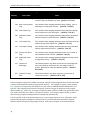
Table 1 - Automating AASHTO Element Generation for Agency Elements ...................................................29
Figure 23- Fragment of Generated AASHTO Element Specifications ........................................................... 31
Figure 24 - Generalized Transform Rule Layout ............................................................................................. 34
Figure 25 - Example Rollup Rule...................................................................................................................... 34
Figure 26 - How-to Read the Migrator Rules Grammar - Syntax and Notation............................................ 35
Figure 27 - ElementDataRowType xml type definition ................................................................................... 47
Table 2 - List of Migrator Rules and Source CoRe Elements ..........................................................................49
Table 3 - Glossary of Terms .............................................................................................................................. 56
viii
Program User Guide– Version 1.1
AASHTO Bridge Element Migration Programs
1. Introduction
Background
In April 2010 the AASHTO Special Committee on Bridges and Structure (SCOBS) Technical
Committee T-18 - Bridge Management, Evaluation, and Rehabilitation (T-18) approved an
updated element condition data specification based on the report AASHTO Guide Manual for
Bridge Element Inspection (BEM) 1 submitted to the committee by its primary authors,
Michael B. Johnson PE (Caltrans) and Paul Jensen PE (previously at Montana DOT). This
manual changed the nature of the bridge element condition assessments significantly, in
particular, providing for multi-path deterioration rather than the single-path deterioration
approach of the previous AASHTO CoRe specification (‘old-style elements’), as well as
standardization of element condition states to 4 for all elements, and organization of elements
into National Bridge Elements (NBE), intended to provide a nationwide reporting standard, and
Bridge Management Elements (BME), intended to augment the NBEs with additional element
types to support bridge management condition data needs. The manual for the new AASHTO
element specification (‘new-style elements’) was first published by AASHTO in January of 2011. 2
The AASHTO member States have a rich body of element data collected over several inspection
cycles, in some cases over more than 15 years. These data were collected in conformance to the
older CoRe specification and incorporate a considerable level of agency modifications to the
standard condition state language as well as extensions with new elements not found in that
specification, such as movable bridge elements.
These data are the foundation for bridge needs assessment and bridge management; preservation
of this history is vital. To that end, a process and supporting software to migrate the elements
from the previous specification to the new specification is of critical importance. T-18 has
sponsored a software design and development project intended to fulfill that need for its member
agencies. This migration utility (the ‘Migrator’ 3) has several salient characteristics that are
elaborated later in this manual. First, the Migrator is entirely conformant with the approved
specification, including the technical appendix D that provides the guidelines and rules for
element transformation between old-style and new-style. Second, the Migrator is entirely
database independent and operates solely on standardized Xml files enforced by schemas, along
with configuration and logging text files. Third, the rules are extensible to permit the several
agencies that have custom elements or have modified old-style elements to incorporate their
changes in the transformations. Fourth, the application provides both a batch processing console
operating mode as well as an interactive rule editing and testing user interface, to support agency
rule review and modifications. The Migrator application has published Xml schemas 4 and is
written with an open application programming interface (API) which permits agencies to
incorporate the migration software tools into their own data processing environments as needed.
1
2
3
4
The BEM Manual is © The American Association of State Highway and
Transportation Officials, January, 2011 – Washington DC.
See BEM, 2011, p. 1-1
Shorthand application name for the AASHTO Element Migration Utility
See Appendix A for the default location of these files
1
AASHTO Bridge Element Migration Programs
Program User Guide– Version 1.1
What is the Migrator? 6 .
The Migrator application offers an interactive environment for setting up and testing element
conversion rules, downloading element data and element specifications, converting existing data
and reviewing results, and setting the program operating parameters. The migrated output file
can be imported to the AASHTO Pontis 5.1.3 application using the built-in import feature of that
application.
A full set of old-style and new-style element specifications, tested transformation rules for NBEs
and BMEs and benchmark test data files are provided with the application. These are intended as
a starting point and will very likely require some additional agency customization to perform the
full migration of CoRe elements to the new specification, particularly if agencies have modified
the CoRe element definitions or added any agency custom elements to their inventory. 7
This user guide provides basic installation instructions, a basic functionality overview, and
examples of GUI operation. Portions of this manual are drawn from the original software design
document which provides additional detail on processing logic, rule specification syntax, and Xml
schemas for each of: 1) old-style and new-style type specifications; 2) conversion rules; and 3)
element condition data exchange formats. Dedicated sections document the migration rules logic
and syntax. It is almost certain that States will have to extend the standard rules to migrate
agency defined elements or to migrate CoRe elements that have been modified, so a user must
become familiar with the rules at a reasonable level of detail.
6
7
2
The author acknowledges that the name ‘Migrator’ is actually not a valid English
word. It has been coined for the purposes of identifying this application.
These resources may be found on the project website at
http://bridgeware.onjira.com. Migrator source code is distributed to member
agencies at the sole discretion of AASHTO.
Program User Guide– Version 1.1
AASHTO Bridge Element Migration Programs
2. Installation Guide
Supported Operating Systems
The programs have the same environment requirements as other AASHTOWare Pontis 5.x programs.
The migration utilities operate only on Intel platforms under Windows XP SP3 or Windows7. The
Migrator programs are 32-bit applications. While no network or database connection is required by the
applications for migration, because the transformation processing operates solely against Xml and text
files, a BRIDGEWare™ database connection would be required to download Pontis CoRe element data to
Xml files for processing.
Basic operating system requirements are
•
•
•
•
•
•
The workstation should have adequate RAM and disk space to run these operating systems
efficiently;
Adequate disk space to store the exported and migrated element xml data files. The programs
take up a trivial amount of disk space;
Windows XP SP3 is supported and most of the internal testing has been performed on this
platform;
Windows 7 - 32 or 64 bit versions. Primary development was performed on a 64-bit platform with
32-bit program build targets;
Windows Vista should work but has not been tested; and
Windows Server versions should work but have not been tested.
Additional Operating Environment Requirements
A workstation also must have the following installed to run the GUI or the command line migration
applications:
•
•
•
•
8
9
10
.NET Framework 4, available for download from Microsoft if needed. 8
.NET Framework 2.0, available for download from Microsoft if needed, is also required for the
log4net utility used to log operations. 9
OLEDB data adapter software for the agency’s Pontis database. This is typically installed by the
Pontis 5.1 installer or may be installed explicitly from the database vendor’s client support disks.
The OLEDB adapter/driver should be compatible with .NET 4.0. 10
A user working directory must be designated where the user has full rights. This can be located
anywhere, but typically would be on the C: or D: hard drive. The command line program always
assumes it is operating ‘locally’ with full directory privileges. The Windows GUI runs from a
Search for dotnetfx40_full_setup.exe or navigate to
http://www.microsoft.com/downloads/en/details.aspx?familyid=9cfb2d51-5ff4-4491-b0e5b386f32c0992&displaylang=en.
Search for dotnetfx.exe or navigate to
http://www.microsoft.com/downloads/en/details.aspx?familyid=0856eacb-4362-4b0d8edd-aab15c5e04f5&displaylang=en.
Installing the .NET frameworks and OLEDB adaptor will require administrator privileges to
install.
3
AASHTO Bridge Element Migration Programs
Program User Guide– Version 1.1
standard Windows application installation location e.g. C:\Program Files
(x86)\AASHTOWare\Bridgeware Element Migrator but starts up in the user’s working
directory that was specified during installation.
Database Requirements
The Migrator programs have no specific database requirements for normal operations as all processing is
performed on Xml and text files. However, for downloading Pontis CoRe element data from a production
system, a standard Pontis/Bridgeware 4.4 or 4.5, 5.0, 5.1 or 5.1.2 database and a client workstation
supporting an OLEDB connection is required. The database vendor may be Oracle, SQL Server, SQL
Server Express, or even Sybase SQL Anywhere. The application has been tested with Oracle 10/11 and
SQL Server Express, but specific database versions were not tested.
The internal SQL used for the download capability is very generic and should work with any recent
release. This SQL is shown in the following figure:
Figure 1 -Element Data Download Sql
Migrator database user privileges
As noted above, the Migrator programs do not require any database at all to migrate element data. They
process and produce xml files. However, most agencies with Bridgeware or Pontis databases will want to
use the built-in extractor to download their element condition data, customized element specifications,
and other information. The user ID used by the Migrator programs to connect to the database should be a
standard Pontis user with standard privileges in the database in order to read from the tables required for
downloading element data and element specifications. The SQL shown in the figure above requires access
to several standard Pontis tables, and a standard Pontis user id typically has all the privileges required.
If Windows Trusted Authentication (Windows domain authentication) is used with SQL Server, then
privileges to connect to the Pontis database must be granted by the operating system. In both
authentication cases, the Migrator utility only requires the ability to connect to the database and select
from the Pontis tables, as the programs perform no database updates, inserts or deletes.
Guidelines for setting up authentication are beyond the scope of this discussion but details and examples
are available in the Pontis user manual or the SQL Server/SQL Express/Oracle built-in help.
4
Program User Guide– Version 1.1
AASHTO Bridge Element Migration Programs
Connecting to a database
In order to use the extract capability of the Migrator to download element conditions and specifications
from a Pontis database, a ‘connect string’ will be required. Typically, this is the same connect string as the
one used by Pontis 5.1 to connect to the database. It is the responsibility of the end user to set up a
working OLEDB connect string for their database. 11
A copy of the 5.1 sample database (from Summer 2011) was used for development of the Migrator. That
database is a SQL Express database. A standard connect string for SQL Express (assuming it is located in
a standard SQL Express data subdirectory in this case) is:
-B ‘Provider=SQLOLEDB;Data Source=REDBANDTROUT\SQLEXPRESS;Integrated
Security=SSPI;Initial Catalog=Pontis51-Sample;Initial File Name="C:\Program
Files\Microsoft SQL Server\MSSQL10.SQLEXPRESS\MSSQL\DATA\Pontis51-Sample.mdf"’
...where the OLEDB Provider is SQLOLEDB from Microsoft, the source in on the workstation
REDBANDTROUT using SQLEXPRESS, the database initial catalog (active database) is Pontis51Sample, and the file name is as shown on the local file system.
Another SQL Express example is:
-B ‘Provider=SQLOLEDB;Server=.\SQLEXPRESS;Integrated Security=SSPI;Initial
Catalog=Pontis51-Sample"’
...where the OLEDB Provider is SQLOLEDB from Microsoft, the source in on the default workstation
using SQLEXPRESS, and the database initial catalog (active database) is Pontis51-Sample.
An Oracle example is:
-B ‘Provider=MSDAORA;Data Source=XE;User ID=VDOT’
...where the OLEDB Provider is MSDAORA provided by Oracle as part of its client software, the data source
name XE is the Oracle SID of the database, which is typically defined in the workstation’s TNSNAMES.ORA
file, and the user id VDOT is a Pontis user from the great Commonwealth of Virginia.
There are a wide variety of connect string possibilities that are beyond the scope of this documentation.
Using valid Pontis 5.x database connect strings is recommended. The Pontis 5.x application provides a
configuration page for creating and testing database connection strings that should be helpful. Once a
valid connection string has been created in Pontis 5.x, it can be copied and pasted into the Migrator
application settings form.
Use of quotes in connect strings
Note that in the SQL Express example above, the fully qualified file name portion is enclosed in double
quotes, so the entire connect string must be enclosed in single quotes. In other situations where the
connect string does not have embedded spaces, it can be enclosed in either single or double quotes.
11
Connection string resources and examples at www.connectionstrings.com may be helpful.
5
AASHTO Bridge Element Migration Programs
Program User Guide– Version 1.1
Installation Summary
An installation program Setup.exe is provided for the GUI installation. Running this program will
install all portions of the GUI, except it does not install the .NET Frameworks or any database vendor
OLEDB adapters, which are assumed to be in place and configured beforehand. The setup program is
available at https://bridgeware.onjira.com/browse/PEMBETA-61. Run the setup program directly or
through the usual Control Panel/Add Programs (Programs and Features for Windows 7).
The prompts are self-explanatory and consistent with any Windows program. The setup program will
prompt for a working directory for the application. If the program has never been installed before, this
will default to C:\Users\<userid>\AppData\Roaming\AASHTOWare\Bridgeware Element Migrator
on Windows 7, and C:\Documents and Settings\<userid>\Application
Data\AASHTOWare\Bridgeware Element Migrator for a WinXP workstation. A reasonable alternate
working directory might be C:\AASHTOWare\Visual Element Migrator. Any local directory may be
used but it must be a normal writable directory in which users have full privileges to read and write files.
During the installation, a working directory structure consisting of the named target and several standard
subdirectories such as Input, Output, Logs, and Temp will be created automatically.
The default install location for the program itself is C:\Program Files(x86)\AASHTOWare\Visual
Element Migrator 1.1. An alternative program location can be specified during installation. Network
install locations have not been tested or certified but may operate properly. No testing has been
performed in a Citrix environment. UNC install paths and file name settings are not supported.
In addition to installing the application, a set of runnable sample and default files will be placed in the
default directory structure. The various Migrator files are documented in later sections of this manual.
Confirm Installation
To verify that the GUI is installed properly, perform the following sequence:
1. Click Start, then locate the program Visual Element Migrator, or click the desktop icon.
2. Double-click or open the program
3. A splash screen similar to the following will be displayed as the program starts up. It will remain
visible while all the data files are loaded and the user interface is launched. The startup process
may be slightly slower on first use of the application during a session or after a new installation,
as a shadow compiled copy of the software is made by the .NET Framework.
6
Program User Guide– Version 1.1
AASHTO Bridge Element Migration Programs
Figure 2 - Startup Splash Screen
After the program loads you will see a main program window similar to the example shown below.
Clicking any row on the list of rule definitions will show the rule syntax.
Figure 3 – GUI Application Opening Screen
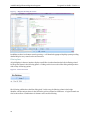
Click on the Settings tab to verify the file locations under the working directory that was specified during
installation. A portion of this screen is shown in the next exhibit.
7
AASHTO Bridge Element Migration Programs
Program User Guide– Version 1.1
Figure 4 - Snippet of Settings Screen Showing File Locations
The file locations should reflect the working directory specified during the installation process. This
confirms successful installation of the program. In this case the install location in the user’s home
directory tree is the default for Windows 7 but any user-writable directory is supported.
Upgrades
The Migrator does not provide a built-in software updating capability. Any upgrades will be installed on
top of the old version by default. If the installer detects that files from the program exist in the target
working directory, it will offer to back these up before uninstalling and reinstalling the application. This is
a convenience and does not and cannot guarantee data security. Users are strongly encouraged to back up
their working directory contents separately to external media beforehand.
Removing the program
An uninstall program can be found in the program’s installation directory or the Control Panel
Add/Remove Programs can be used to remove the program. Any files created or modified by the user in
the working directory structure may not be successfully removed by the uninstall program and will have
to be removed individually after the process completes.
8
Program User Guide– Version 1.1
AASHTO Bridge Element Migration Programs
3. Using the Visual Element Migrator
•
•
•
User Interface Overview
The desktop is organized into 4 tabs that correspond to each of the major application modules which are
described below. To support these, a common set of tools are provided on the desktop for activity
monitoring, showing popup tooltips, launching the help system, and exiting the application. The user
interface does not use any conventional menus.
The key characteristics are:
•
•
•
The user interface is the mouse, which performs the select, edit and button functions. As in the
command interface, diagnostic and progress messages are printed to the screen or saved to log
files.
The GUI uses separate modules for: 1) writing, editing and compiling rule sets for use in data
transformation, 2) importing and manipulating a set of CoRe data for transformation and 3)
running a transformation from CoRe to AASHTO data sets.
These modules are contained in a single set of tab panes accessible by launching the AASHTO
Element Migrator program in windows. Each module corresponds to a key aspect of the
migration process and is designed to be used in sequence with the other modules.
All of the GUI Migrator program’s behavior is managed through the Settings module, which is
used to configure all the operating parameters and the files the Migrator uses in performing
transformations on the dataset.
Desktop tools
There are four tools that are available throughout the application. These are shown in the following figure
showing the desktop. The control panel at the bottom of the screen includes:
•
•
•
•
The View button displays a log of actions performed in the session. This displays a popup window
which permits the user to print, save the messages to a PDF file or to clear the system message
history.
The Help button, with a question mark icon, displays the full help for the application, based on
portions of this guide.
The Show Tooltips checkbox will set the application to show detailed tooltips for user interface
elements.
The Exit button will shut down the Migrator. The application can also be closed with the normal
Window close button in the upper right corner.
9
AASHTO Bridge Element Migration Programs
Program User Guide– Version 1.1
Figure 5 – Migrator Desktop Overview
In addition to these icon button controls, pressing F1 will launch the popup tooltip help system providing
detailed help for every control on the user interface.
Filtering Data
All grid displays in the user interface display a small filter icon that launches the built in filtering wizard
for the grid as shown in the following picture. Clicking on this icon reveals a filter dialog which permits a
wide variety of filtering options.
Figure 6 - Filter Tool Icon
The following exhibit shows the filter dialog itself. In this case, the filtering column is the bridge
identifier, and the unique values for the field in the grid are all listed as checkboxes. A logical formula can
also be entered here. Combinations of columns can be used for filtering.
10
Program User Guide– Version 1.1
AASHTO Bridge Element Migration Programs
Figure 7 - Filter Options Dialog
Sorting Data
The grids can be sorted by clicking on the headers, and multiple columns can be combined for sorting by
clicking on the column headers while holding down the Shift key. Click the columns repeatedly to toggle
the sort order and to clear the sort.
Modules
Module 1 – Edit Migrator Rules
The Edit Migrator Rules module is used to collect and edit the rules for migrating CoRe elements to
National Bridge Elements (NBEs), Bridge Management Elements (BMEs) and Agency-Defined Elements
(ADEs), as well as generating Defect Flags (SF). The rule definitions can also automatically associate
elements and protective systems as well as tag elements with rollup NBE targets, used to consolidate
families of related sub-elements e.g. girders and beam ends for national reporting purposes.
The rule screen is split between a text editor used to modify the rules and a set of columns displaying data
on the rules themselves. The rules are listed by Rule ID. The text editor allows you to modify any of the
set of default rules to fit your needs.
11
AASHTO Bridge Element Migration Programs
Program User Guide– Version 1.1
Figure 8 - Rules Editing Screen
The Rules module lets you quickly switch between multiple compiled rule sets using the Load button,
which can incorporate any rules file in xml format as the rules dictating the transformation of CoRe
elements. The New and Copy buttons are relatively self-explanatory; Copy requires the selection of a rule,
or a range of rules, and the rules will appear with a default name in the column list.
The Remove button takes a rule out of a list. If you don’t save at this point, however, the rule will not be
eliminated from the dataset. The Save button by default will only save those entries selected in the list.
Save validates the rule or rules when it runs, and will not complete if the rule set contains errors.
The last two buttons, Validate and Compile, are used to prepare an edited rule set for output as a
rules .xml file to be used in the migration process. Validate checks the correctness of the rules according
to the syntax laid out in chapter 5 and registers any errors in the file Parser.err (located in the Output
subdirectory). Compile generates an .xml file which serves as an input in a later part of the procedure.
The compilation process does not generate any output if the rule set doesn’t parse and validate correctly.
Editing Rules
Rules can be edited by typing in the right hand column. Certain keywords and directives will
automatically be highlighted for readability, but the syntax is not checked dynamically. After a rule body
is created, it should be validated using the Validate button and any errors should be corrected. Rules are
not saved until the Save button is pressed, however, you can move between rules and copy and paste
between them.
Rules can be added with a stub layout by using the New button. These rules have the right layout but do
nothing. Typically it is preferable to copy a working rule to a new rule. In that case a new entry will be
generated and it will automatically be named and numbered with defaults that should be changed.
12
Program User Guide– Version 1.1
AASHTO Bridge Element Migration Programs
Examples of rule bodies generated both ways are shown below. The first example show s a copy of rule
4315 which is identical to the original and would typically be changed to a new ID and a new very similar
target element, perhaps an agency-specific type of disk bearing.
Figure 9 - A Copied Rule
The next exhibit shows a starter rule body ‘stub’ that provides a framework for writing a new rule but will
not compile or do anything until revised.
Figure 10 - New Rule Stub
Rule ID Convention
The convention for identifying rules used in the default set is as follows:
•
•
•
1st digit – major element category. These are 1 – superstructure; 2- substructure; 3 – joints; 4bearings; 5 – approach slabs; and 6 – decks and slabs. Smart flag rules start with a 7, and agency
element rules start with an 8.
Next few digits – the element key, with leading zero for sorting convenience. 6012 would be a bare
concreted deck, for example.
Final characters- an indication of whether Smart Flags are involved in the rule or not, or a tag for
a rule variant as appropriate. For example, ‘NSF’ means does not use smart flags in the rule,
while ‘SF358SF359’ means both smart flags 358 and 359 are considered in the rule, for an
element on a bridge where these smart flags are found.
13
AASHTO Bridge Element Migration Programs
•
Program User Guide– Version 1.1
Using this convention, then, a rule ID 6012SF358SF359 would pertain to deck, type 12, for a
bridge with both 358 and 359 smart flags.
Documenting Rules
The example rules shown provide comments throughout. Liberal use of comments is strongly
recommended since there are many engineering assumptions intrinsic to these rule bodies which should
be communicated to other interested parties in an agency. Comments may be extensive over multiple
lines using the /* */ format or follow the one comment per line // format as appropriate. Comment
formats are described in the later section on rule syntax.
Module 2 - CoRe Elements Data
This module shows the specific CoRe data to be transformed and includes tools for downloading and
migration of the data. No element data editing is provided as that is the responsibility of the source
program (typically Pontis™). The screen contains columns for Summary, Total Quantity, State
Quantities, Bridge Key, Inspection Date, and other standard element data items. Using the filter function
on this screen allows you to sort and sift through the CoRe elements according to any of these criteria. By
default, it sorts according to Bridge Key.
This module deals with CoRe elements, and the program defaults to displaying ten elements per page. If
you need to deal with the whole dataset, click View to open the entry log for the program, note the number
of elements comprising this set and instruct the program to display a higher number per page than exists
in the whole of the set. This applies to Module 3- Migrated NBE/BME/ADE Data, as well.
The functions on this page are always dependent on the selection and editing of rules in the previous
module. The rules module tells the Migrator exactly what transformations to perform on the CoRe
element data. Therefore, make sure to proceed with your migration from leftmost to rightmost module.
The Download button connects to a SQL server to download element data files for import into the
Migrator. This button also downloads and generates an operating environment Xml file based on the
current Pontis element definitions for use with the Migrator.
Save and Load perform similar functions as in the Edit Rules module- Save creates a .xml file composed
of all elements selected when the button is clicked and Load imports such an .xml file into the Migrator.
The files are validated as they are imported and no data will be loaded if the files do not pass validation
according to the ElementData – 7.xsd schema. 12
The Migrate List function only affects the highlighted rows, or if no rows are selected, the entire list of
data in the grid. Assuming that everything in the Settings module is set correctly (see below), the
Migrate List button transforms the selected CoRe elements data set into NBE’s, BME’s and ABE’s
according to the rules set in place in the Edit Migrator Rules module. The file format for the migration
output is .xml.
Module 3- AASHTO Elements
This module displays the results of migration from CoRe to AASHTO NBE’s, BME’s, ADE’s and DF’s. The
column structure is identical to that found in Module 2 – CoRe Elements: Summary, Total Quantity,
State Quantities, Bridge Key, Inspection Date, Inspection Key, Element Key, Environment and Structure
12
14
Validation of xml files against the appropriate schema is automatic. No data can be loaded that does
not pass validation. More information about xml file validation is available in any xml guide.
Program User Guide– Version 1.1
AASHTO Bridge Element Migration Programs
Unit. These columns are augmented with the optional NBE rollup element keys, and, for protective
system BME elements, the associated primary structural element.
Migrate a File draws on an existing CoRe elements .xml file to generate a set of NBE elements displayed
on the screen.
Save Results and Load Results in this module are mechanically identical to those in the second module,
with the exception that the targets are slightly different; The third module is a collection screen designed
to give the user the ability to access and manipulate a migrated data set. Therefore, where the second
module stored its files as .xml files of migrated data, the third module lets the user get a specific set of
data from a larger set. This is technically possible in the second module as well, but the third module uses
the same function on the same CoRe dataset to display the new NBE/BME/ADE data. Whereas you see
the input files and generate a more specific set on the second module screen, the third module allows for
display and manipulation of the output files.
Module 4- Settings
The Settings module manages all the options for modifying the Migrator operating parameters. The top
two lines are used to set the connection strings and the where clause (filter) for downloading some or all
CoRe Element data from a Pontis database into the Migrator utility. The various checkboxes and input
fields on the row below allow for defining a common characteristic for the selected elements. Below that,
the file list sets each of the files used by the Migrator GUI as it imports, validates and transforms
elements. Some of the file names are fixed and the user cannot change them. All the settings on this page
must be saved before the application will use them for processing. Press the Save Settings button near
the bottom of the page to apply the choices. File name selections, however, are automatically applied by
the file selection dialog.
Figure 11 - Settings Module Main Screen
15
AASHTO Bridge Element Migration Programs
Program User Guide– Version 1.1
Download settings
The first set of functions on the Settings page consists of the Test Connect button, and the Connection
String, Cutoff Date and WHERE clause operating options.
Configuring the database connection
In order to connect to a Pontis database and download data, a valid, working connection string must be
provided for the application. If only a subset of the core element data is required, a WHERE clause can be
entered that will restrict the rows that are downloaded.
Connect String – This field shows the OLEDB string used to connect to an exterior database. These were
discussed earlier in Chapter 2. The database connection string is used by the application to connect to a
Pontis database using the OLEDB protocol. This connection string should be configured and tested
outside of the application, then pasted here. The Migrator application does not itself provide functionality
to build connection strings.
Test Connect - Once a connect string has been entered, use the Test Connect button to check the
connection before downloading files. This test also will automatically append the contents of the WHERE
clause to the download SQL to evaluate its syntax.
Setting the download criteria
The WHERE clause setting filters the downloaded element data. An individual bridge can be specified, for
example, or bridges with a particular element type. When the Migrator connects to a database to extract
data, it automatically chooses to grab all the existing element condition data unless a WHERE clause is
provided that selects a more restricted set of information. The WHERE clause does not need to start with
WHERE but must show the full table name for any column that is used in the WHERE clause e.g.
BRIDGE.BRIDGE_ID=’XYZ’, not BRIDGE_ID = ‘XYZ’. As noted above, the Test Connect button will
automatically append the WHERE clause to the SQL and check its syntax.
Cutoff Date specifies the span of years for which the Migrator will collect data. It assumes that the user
always wants data up to the present time, so Cutoff Date only specifies a beginning point for retrieval.
Using this option permits the user to select data on or after a particular date. This field provides a
calendar picker for data entry or the date may be entered directly.
It is important to note that the Cutoff Date and the WHERE clause can be applied separately or in
combination. When used in combination, this can lead to unexpected results if the Cutoff Date makes the
WHERE clause criteria irrelevant and vice versa. For example if all element condition data is requested
for all inspections after a particular date, but the WHERE clause selects specific bridges that do not happen
to have any inspections after that date, then no data will be selected and downloaded.
Data recoding settings
The five settings below each force a set of migrated output elements to have the same shared
characteristic, which is set using the text input box to the right of each key. These buttons correspond to
the flags discussed in the command line operation instructions. None of these special recoding settings
are required during normal migration operations.
Checking these boxes and entering a value will force all entries to use that attribute upon migration. For
example, all the generated elements can be assigned to one structure unit and can all be associated with a
single inspection key for easy reference, if desired. If none of these options are set, then the original
characteristics will be preserved during migration.
16
Program User Guide– Version 1.1
AASHTO Bridge Element Migration Programs
BRKEY sets a common database key ID for the bridge the migrated element(s) rest(s) on, equivalent to the
command line flag –B.
UNIT sets a common value for the superstructure unit to which the element(s) will be assigned, equivalent
to command line flag –S.
INSPKEY sets a common inspection ID for the migrated element(s), equivalent to command line flag –I.
This may be useful to be able to easily identify the initial migrated element records in the target database.
This should only be used if the set of records to be migrated includes just the latest inspection for each
bridge or unwanted ambiguity may result.
ENVKEY sets the physical/operational environment for the migrated elements, equivalent to command
line flag –E.
INSPDATE sets a common date of inspection for the migrated element(s), equivalent to command line flag
-D. This field will show a calendar picker for data entry. This field should likely be used in combination
with the INSPKEY setting in most cases.
Additional Options
These settings are related to the source and target data in the migration and logging. These are displayed
in the following screen fragment:
Figure 12 - Additional Transformation Options
Data may be submitted for migration in either Metric or English and can be emitted from the Migrator in
either Metric or English Units of Measure (UOM). The source and target data may be either percentages
or quantities. A dropdown is shown that permits selecting one of these options.
The M|MP|E|EP controls (input and output) determine the units of measure used by the input and
output datasets; the metric (M) and English (E) quantity measurements can also be processed as
percentages for a condition state (MP, EP). For example, with M selected as an input, the Migrator will
assume that it is receiving true measurements, while selecting MP will make the Migrator look for a
percentage in a condition state of a total metric quantity. The same applies for English measurements.
All the source data condition state percentages are checked to make sure they add up to 100%. An error
will be logged if these data do not add up, but the program will attempt to fix the data on the fly by adding
or removing from State 1. Nevertheless, it is not recommended that the data have significant
normalization problems when used for migration.
17
AASHTO Bridge Element Migration Programs
Program User Guide– Version 1.1
The output UOM can be set as well, performing metric English conversion on the fly during
transformation using the standard element conversion factors found in the conversion schema Xsd file.
Further, the output can be in either quantities or percentages.
Combine adds elements of the same type together when they occur on multiple structure units for a
bridge. This collapses detail but may be appropriate in some cases. This is a true/false toggle button
which will be a contrasting color if enabled.
Scaler (-XO/-XI) defaults to maintaining the same scaler for input and output quantities. If the button is
pressed, the Migratory will ignore scalers and treat the element as raw data. This is a true/false toggle
button which will be a contrasting color if enabled.
Verbose/Terse (-V) refers to the level of detail in the transform processing log. It defaults to verbose
descriptions. This is a true/false toggle button which will be a contrasting color if enabled.
Miscellaneous Settings
The Themes button allows the user to change the appearance of the program. It defaults to the typical
Microsoft™ Office Blue similar to the default for Microsoft Word™ and after a confirmation dialog,
automatically restarts the application to apply the new theme. This button is disabled if there are any
pending changes. 13 Clicking the button pops up a list of available themes with buttons showing the theme
effect. The choice of theme is persisted between sessions.
Figure 13 - Theme Selections
Getting help
Press F1 at any time to reveal popup help for the various screens and controls, as well as descriptions of
each of the files used. Press the question mark on the bottom of the screen to show the full online help
(generated from this manual).
13
18
The Expression Dark and Windows 8 Metro themes are not supported by the application.
Program User Guide– Version 1.1
AASHTO Bridge Element Migration Programs
Using the grid view
A primary advantage the GUI has over the command line interface is the ability to display and manipulate
all of the data in a dataset at once. The GUI uses a columnar structure with the ability to select and filter
each column according to specific criteria.
The generic structure of the columns looks like this:
Figure 14 - Standard Data Grid
This image is taken from the main screen of the CoRe Elements module. The columns are completely
resizable, but default to a standard size upon opening.
Selecting data from the list
The user selects, manipulates, compiles and migrates data based on the selections in this pane, so it’s
critical to understand how it works. You can only select entries by clicking on them directly, so that the
entire row becomes highlighted, or by shift-clicking to select an entire range. Use control-click to select
and deselect individual entries. If nothing is selected, then the program assumes all the rows should be
processed. If you make selections but do not select an entry so that it’s highlighted, then when you click a
command button, it will not be included in the set of data to be processed. In the example above, if you
were to save this entry as a completely new set of CoRe Elements, only the first 3 lines would be saved to a
new set.
If you’d like to select every element in a given set, set the Page Size , which is the number of entries
displayed per screen in the grid, to an arbitrarily large number (greater than the number of elements
present in your data). Click the checkbox on the left-hand side of the column headings to select every
entry on the screen. If you unselect all data rows, the entire set of data is saved by default.
19
AASHTO Bridge Element Migration Programs
Program User Guide– Version 1.1
There is typically no need to save multiple copies of the source data as it can be downloaded again at any
time from the source Pontis database, but it may be helpful to create small test subsets to use for testing
rules against specific element types.
Sorting the data
You can also click the column headings to make the whole set (selected and unselected) sort according to
that column. After 3 clicks, it sorts by the left-most column (summary in the example above). Holding
down the shift key permits a cumulative sort on multiple columns. The sort direction is indicated by a
small twistie in the column heading.
Applying filters to the data
The Migrator utility includes a filter function used to quickly assemble specific sets of data. The menu is
accessed by clicking on the small filter icon in the header of each column (see below). This brings up a
menu with an itemized list of all the entries in the current list with checkboxes allowing you to include or
exclude them in the dataset you want to migrate. Selecting multiple items in the drop down list, or
filtering out unwanted entries reduces the active entries that will be processed by the Migrator. If you
want to turn them into a usable extract dataset, use the Save button as detailed above after filtering out
unwanted elements.
Figure 15 - Filter Tool Icon in Column Header
In addition to individual selection by value, the Migrator filtering tool also provides a number of standard
logical filter options.
The logical filters are as follows:
•
•
•
•
•
•
•
•
Is equal to
Is not equal to
Starts with
Ends with
Contains
Does not contain
Is contained in
Is not contained in
In addition to these logical operators, the filters can be set with both entry fields as well as an ‘and/or’
clause. In a complicated situation, you can have multiple criteria including both directly selected data
values and logical filters at work on a single set of data.
20
Program User Guide– Version 1.1
AASHTO Bridge Element Migration Programs
If, in the Edit Migrator Rules module, you want to see all rules pertaining to deck and slab elements,
which by Pontis convention have an ID starting with the number 6, enter the following into the summary
column:
Figure 16 – Filter Rules by First Digit of Rule ID
The grid then displays all the entries beginning with a ‘6’, which is the decks and slabs category.
If you want to filter out everything with a name that doesn’t contain concrete or timber, enter the
following into the second column:
21
AASHTO Bridge Element Migration Programs
Program User Guide– Version 1.1
Figure 17 - Filter Rules to Exclude Materials
It is possible to filter each column according to specific, separate parameters.
Filters are not reapplied upon reopening the program.
Clearing filters
The filters will not reset unless you either close the program or click “Clear Filter” from the filter popup
menu
4. Conversion Rule Guide
Background
The 2011 first edition of the AASHTO Guide Manual for Bridge Element Inspection (the ‘BEM’) included
a technical Appendix D with transformation rules for CoRe elements expressed in graphical and outline
terms. The Migrator was designed provide a means to embed this rule logic in its element data migration
processing in a configurable manner. To that end a comprehensive rule language has been defined which
is used to express the conversion logic. A full set of tested rules for every AASHTO CoRe element is
provided with the software.
22
Program User Guide– Version 1.1
AASHTO Bridge Element Migration Programs
The rules have a source scope, meaning that they may apply to one element, several elements, a type of
elements, or an element category, taken in reverse hierarchical order from a rule for an individual
element down to a rule for a category (list). This flexibility of scope permits fewer rules to transform more
elements.
The rules also incorporate the effects of Smart Flags when applicable and encountered in the incoming
condition data. Some elements are affected by Smart Flags, such as decks which may be influenced by the
soffit and deck cracking flags, and others are not. For the ‘no-Smart-Flag-influence’ situation, the
transformations are relatively straightforward mappings of old and new condition states. For the
situation where smart flags apply, their existence on a bridge must be considered during conversion and
embedded in the logic. In the new specification Smart Flags are now termed Defect Flags.
Special functions are used to associate elements with other elements and Smart Flags either on the same
structure anywhere, or on the same user-defined unit of the structure (e.g., structural frame).
It is also possible to associate protective system bridge management elements with any inventory element
on the fly, and to create a rollup linkage for any element to collapse the condition distribution for BME’s
and ADE’s to National Bridge Elements for Federal reporting purposes or cross-comparisons between
States.
The rules for element conversion in the Migrator follow the approach of Appendix D of the original BEM
document. The rules were developed from the examples in that appendix originally and have been
significantly refined and improved during the course of the development of the Migrator. The Migrator
includes a full set of rules for every standard Pontis CoRe element with variations considering the
influence of Smart Flags or the existence of other elements on the structure
Rule Syntax
Typical conversion rule logic for each is shown in the following 3 figures.
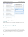
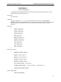
Syntax for a Simple Element Migration Transform Formula
The figure below 18 shows the simple case of state to state assignment for element 104 without
consideration of smart flags. This just requires deciding which source states map to which target states
and in what percentages or sums over source percentage. The example source code is what the end user
would enter as a formula, which is then parsed, validated, and stored in tokenized form in an Xml file for
use in migration processing.
18
All examples shown here are taken from the file Default-Rules-Input.txt distributed with the
Migrator
23
AASHTO Bridge Element Migration Programs
Program User Guide– Version 1.1
Figure 18 - – Migration Rule Source Example – Prestressed Concrete Box Girder (104)
TRANSFORM("1104", "PS Concrete Box Girder (104)");
SCOPE (ELEM_LIST, 104);
EXCEPTION(101,"Runtime exception when trying to apply rule 1104, PS Conc Box Girder (104)");
// ==========================================================================================
// Update History:
// Version 1.1 - March 30, 2012
// ==========================================================================================
// Commentary
// ==========================================================================================
//RAE - 7/21/11 - checked
// TST 9/27/2011 - Checked and Works
//
// BEM Reference D.2.2.1a
//
CASE
WHEN (1) THEN
ASSIGN_QUANT(THIS) = QUANTITY(THIS);
ASSIGN_PCT(THIS, 1) = PCT(THIS, 1);
ASSIGN_PCT(THIS, 2) = PCT(THIS, 2);
ASSIGN_PCT(THIS, 3) = PCT(THIS, 3);
ASSIGN_PCT(THIS, 4) = PCT(THIS, 4);
END;
// if commonly spalled in State 1, this alternate transformation model can be used to downgrade State 1
// direct assignment of target state 1=0 shown for clarity – not required
//CASE
//WHEN (1) THEN
//ASSIGN_PCT(THIS, 1) =0;
//ASSIGN_PCT(THIS, 2) =SUMPCT(THIS, 1,2);
//ASSIGN_PCT(THIS, 3) = PCT(THIS, 3);
//ASSIGN_PCT(THIS, 4) = PCT(THIS, 4);
// END;
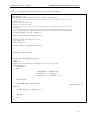
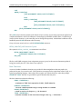
Syntax for a Formula Using Smart Flags
The next figure outlines the more complicate case of an NBE deck type 12 with no asphaltic wearing
surface and smart flags 358 (deck cracking)
24
Program User Guide– Version 1.1
AASHTO Bridge Element Migration Programs
Figure 19 - Migration Rule Source Example – Deck 12 with Smart Flag 358
TRANSFORM("6012+SF358", "Decks/Slabs 12 - SF 358 only - No Wearing Surface and/or Protection System(s)");
SCOPE (ELEM_LIST, 12);
EXCEPTION(101,"Runtime exception when trying to apply rule 6012+SF358");
// ==========================================================================================
// Update History:
// Version 1.1 - March 30, 2012
// Version 1.2 - June 27. 2012
// ==========================================================================================
// Commentary
// ==========================================================================================
// All 3 of these CoRe deck elements become a type 12 in the new specification (consolidated)
// Decks/Slab elements 12 all go to AASHTO 12
//
// None of these elements have wearing surfaces
//
// Handles case when 358 exists but not 359
// Core 358 was 4 CS
// AASHTO 358 is 4 CS
//
// Add Deck Protection System where applicable
//
//
//
// 12/08/2011 - Ready for Review
//
//
//
CASE WHEN (EXISTS(358) AND NOT EXISTS(359))
THEN
// ARMarshall
// Applies to all the elements in the SCOPE, so just use 1 for true here
// CASE WHEN (THIS=12)
CASE WHEN (1)
THEN
//
ASSIGN_QUANT(12) = QUANTITY(THIS);
ASSIGN_PCT(12, 3) = PCT(358, 4);
ASSIGN_PCT(12, 2) = SUMPCT(358, 1, 3);
//
BEGIN_LINK(358)
ASSIGN_QUANT(LINK) =
QUANTITY(THIS)
;
ASSIGN_PCT(LINK, 3) =
PCT(358, 4);
ASSIGN_PCT(LINK, 2) = SUMPCT(358, 1, 3);
//
END_LINK;
//
END
END;
25
AASHTO Bridge Element Migration Programs
Program User Guide– Version 1.1
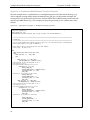
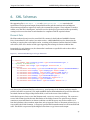
Syntax for a Complicated Multi-Element Transform Formula
The final example shows a complicated case of a multipath migration rule CoRe element deck type (13)
with an asphaltic wearing surface and the deck Smart Flags (358,359). In this transform formula, the
wearing surface is logically split from the source element and becomes a BME element 510 while the deck
itself becomes NBE element (13). This example just shows the processing for one condition state of the
element.
Figure 20 – Appendix D, Example 3 - Multipath Example (partial)
TRANSFORM( "6012+SF358SF359","Decks/Slabs 12 with both SF 358 and 359 - No Wearing Surface and/or
Protection System(s)");
SCOPE (ELEM_LIST, 12);
EXCEPTION(101,"Runtime exception when trying to apply rule 6012+SF358SF359");
…
…
// ==========================================================================================
// Commentary
// ==========================================================================================
// All 3 of these CoRe deck elements become a type 12 in the new specification (consolidated)
// Decks/Slab elements 12 all go to AASHTO 12
//
// Both Smart Flags are found along with the deck element
// Smart Flag - CS 358 in CS 1
//
CASE
WHEN (EXISTS(359) AND EXISTS(358)) THEN
CASE
WHEN (PCT(358, 1 ) = 100) THEN
CASE
//
WHEN (PCT(359, 1) = 100) THEN
ASSIGN_QUANT(12) = QUANTITY(THIS);
// 358 controls so all of deck goes to CS 2
// 358 will go to CS 2
// 359 place holder Quantity of 1 to CS 2
ASSIGN_PCT(12, 2) = 100;
BEGIN_LINK(358)
ASSIGN_QUANT(LINK) = QUANTITY(THIS);
ASSIGN_PCT(LINK, 2) = 100;
END_LINK;
// Quantity 1 (1 sq meter in this case)
BEGIN_LINK(359)
ASSIGN_QUANT(LINK) = 1;
ASSIGN_PCT(LINK, 2) = 100;
END_LINK;
WHEN (PCT(359, 2) = 100) THEN
ASSIGN_QUANT(12) = QUANTITY(THIS);
// 358 controls so all of deck goes to CS 2
// 358 will go to CS 2
// 359 place holder Quantity of 1 to CS 2
ASSIGN_PCT(12, 2) = 100;
BEGIN_LINK(358)
ASSIGN_QUANT(LINK) = QUANTITY(THIS);
ASSIGN_PCT(LINK, 2) = 100;
END_LINK;
// Quantity 1 (1 sq meter in this case)
//
BEGIN_LINK(359)
ASSIGN_QUANT(LINK) = 1;
ASSIGN_PCT(LINK, 2) = 100;
END_LINK;
…
…
26
Program User Guide– Version 1.1
AASHTO Bridge Element Migration Programs
From these examples of increasing complexity, the ability to handle different conversion logic with the
formula language is demonstrated. In the most elementary example, assignments are made 1:1 between
states in the old specification and the new. In the most complicated example, a decision tree is followed
which recognizes the existence of smart flags to adjust the assignments, and even to generate a new
element dynamically when a particular smart flag is in place. A new element will also be generated when
the current CoRe element specification incorporates a protective system which is separated out in the new
specification.
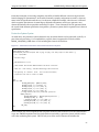
Protective System Syntax
As noted above, the protective system element for any structural element can be generated ‘on the fly’ as
part of the rule processing. To accomplish this, a special clause is supported in each rule called a
BEGIN_LINK/END_LINK clause. A rule including this clause is shown below.
Figure 21 - Automatic Generation of Associated Protective System
TRANSFORM("1101", "Unpainted Steel Box Girder (101)");
SCOPE (ELEM_LIST, 101);
EXCEPTION(101,"Runtime exception when trying to apply rule 1101, Unpnt Stl Box Girder ");
// TST - 10/19/2011 //
// No Smart Flags
//
// BEM Reference D.2.1.3a
//
// CoRe Element 101 becomes AASHTO element 102 after conversion
//
// Adds 515 - Prot Coating - Assumes Weathering Steel Protection
//
// 515 Quantity is a default value – must be field verified//
// Inspectors will need to convert to AREA
//
//
CASE
WHEN (1) THEN
ASSIGN_QUANT(102) = QUANTITY(THIS);
ASSIGN_PCT(102, 1) = PCT(THIS, 1);
ASSIGN_PCT(102, 2) = PCT (THIS, 2);
ASSIGN_PCT(102, 3) = PCT (THIS, 3);
ASSIGN_PCT(102, 4) = PCT (THIS, 4);
// assign default value for protective system 515
BEGIN_LINK(515)
ASSIGN_QUANT(LINK) = @DefaultQuantityConstant ;
ASSIGN_PCT(LINK, 1) = 100;
// ASSIGN_PCT(LINK, 2) = PCT (THIS, 2);
//ASSIGN_PCT(LINK, 3) = PCT (THIS, 3);
//ASSIGN_PCT(LINK, 4) = PCT (THIS, 4);
END_LINK;
END;
In this example, the source unpainted steel box girder element (CoRe element 101) will be transformed to
a type 102 AASHTO unpainted steel box girder with an associated 515 protective system, which is in this
case is the weathering steel system. This will only occur if the source element rule includes this
27
AASHTO Bridge Element Migration Programs
Program User Guide– Version 1.1
BEGIN_LINK clause and is of the appropriate type as indicated. With this mechanism, the protective
rating elements are automatically available in the latest format for use with Pontis 5.1.2 and can be rated
by the inspector during the next visit. As shown in this example, the amount of weathering steel is set to a
default quantity in condition state 1, so the distribution of condition of the weathering system must be
confirmed by subsequent field observation and measurement.
Rollup Rules
The new AASHTO specification distinguishes between National Bridge Elements (NBEs), Bridge
Management Elements (BMEs) and Agency-Defined Elements (ADEs) and also supports Defect Flags
(DF) as the successor to Smart Flags. The BEM provides for the possibility that any NBE may be the
result of consolidating the condition assessments of all the BMEs and ADEs that are related to it - for
example, the beam ends are a BME which related to the girder as a whole- and that ‘roll-up’ logic may be
required during data processing to report NBE quantities and condition state distributions. To support
this, the NBE element ID must be related to the BME/ADE element. The Migrator rule language provides
a ‘ROLLUP’ rule that can be used with any ‘child’ element to determine its NBE ‘parent’. The target NBE
and the source BME/ADE element or elements appear in the ROLLUP statement. The format rollup rule
syntax is as follows:
Figure 22 - Rollup Rule Syntax
ROLLUP-RULE-BODY:
[ EXCEPTION ( <error number> [, <double-quoted error message>] ) ; ]
{ ROLLUP-DIRECTIVE [ ROLLUP-DIRECTIVE]… }
ROLLUP-DIRECTIVE:
ROLLUP(<NBE element number> , ELEM-LIST-SCOPE);
No rollup rules are provided with the default set of rules.
Understanding Rule Processing Behavior
Rule processing is sequential and operates essentially on one element condition data row at a time, while
considering if there are associated elements on the same bridge. The key processing behaviors to
recognize are that there are multiple dependent rule chains for elements, no consideration of element
condition history, and that structural element associations e.g. presumed interactions must be specified in
the incoming data to affect the migration logic.
Rule Chaining
Any 1 rule may not be able to address all the logical possibilities for converting a particular element. In
fact, for easier comprehension and maintenance, it is preferable to split the rules for an element by
complexity. The Migrator will determine the rule set for a particular element in advance and then traverse
the set of rules until an appropriate rule is found . This means that an element with associated smart flags
may be processed by a ‘later’ rule than one that does not have smart flags. This should be considered
when defining new rules both to simplify the logic of any one rule and to ensure that all possible paths or
combinations are covered by a rule.
Combining Duplicate Elements
If the same element appears more than once on a bridge in the input data, the program can be configured
to combine the element in the output data into one new element record, with the quantity and state
28
Program User Guide– Version 1.1
AASHTO Bridge Element Migration Programs
distributions reflecting the total. This is the default behavior. Using the –M flag in transform mode, the
Migrator can be configured to preserve the multiple element instances in the output data. It should be
noted that the Pontis database does not permit the same element to appear more than once on the same
structure unit of a bridge so this combinatorial behavior corrects referential integrity issues automatically
in the default mode.
Deprecating Elements
A number of elements that exist in the CoRe specification are now deprecated. The rule processing
accounts for this because it is driven not just by the input elements allowed but the targets as well, as
defined in the element specification configuration file. If an element exists in CoRe but is non-existent in
the new AASHTO elements, no rule can have that element as a target for output or an error will be
generated.
Transferring Custom Element Specifications
The new AASHTO element numbers were selected without consideration of individual State element
numbering systems used with Pontis. It is therefore possible and even likely that a standard AASHTO
element ID conflicts with a State ID for an agency defined element. This situation can be easily overcome
by small changes to the element definitions table ELEMDEFS in Pontis 4/5.x, which will automatically
generate new renumbered element specifications for agency elements as part of the Migrator’s download
process. The source element data does not have to be changed at all – only the Notes column of the
element definition (editable in the Pontis 4x configuration module).
In order to indicate that a particular agency element should be redefined in the Migrator element
specifications (renumbered), the element definition Notes column must be edited similar to the following
examples 21:
Table 1 - Automating AASHTO Element Generation for Agency Elements
Element Definition Coding For Automated AASHTO Element Generation
Elemkey
21
Short Name
Notes
12
Bare Concrete Deck
This element defines those concrete bridge decks with no surface
protection of any type {AASHTO: 601,DF;602,DF;603 }
{AASHTO: 604;605;606 ; 600} and constructed…
13
Unp Conc Deck/AC
Ovl
This element defines those concrete bridge decks with no surface
protection of any type. {AASHTO: 602; 603; 600 } The deck…
140
Unpainted Stl Arch
This element defines all members of only those steel arches that
are not painted or are {AASHTO: 605} constructed…
216
Timber Abutment
This element defines only those abutments constructed {AASHTO:
605} of timber...
356
Steel Fatigue Smart
Flag
This flag exists only on those bridges with steel elements which
are already showing fatigue damage. {AASHTO: 7356,DF}
this is just a partial list of AASHTO elements
29
AASHTO Bridge Element Migration Programs
Program User Guide– Version 1.1
Element Definition Coding For Automated AASHTO Element Generation
Elemkey
Short Name
Notes
357
Pack Rust Smart Flag
This flag defines only those connections (including shapes in
contact in built-up members) of steel {AASHTO: 7357,DF}
358
Deck Cracking Smart
Flag
This condition state language addresses deck cracking. Once a
deck begins to show other distress… {AASHTO: 7358,DF}
359
Soffit Smart Flag
This condition state language addresses deck distresses through
visual inspections of the deck soffit… {AASHTO: 7359,DF}
360
Settlement Smart
Flag
This condition state language addresses substructure settlement
distresses which are evident during… {AASHTO: 7360,DF}
361
Scour Smart Flag
This condition state language addresses scour distresses which are
evident during visual inspections… {AASHTO: 7361,DF}
362
Traf Impact SmFlag
This condition state language addresses distress of any elements
(mainly superstructure) due to… {AASHTO: 7362,DF}
363
Section Loss Smart
Flag
This condition state language addresses section loss in areas of
steel members which warrant… {AASHTO: 7363,DF}
364
Bridge Rail Smart
Flag
This condition state language addresses damage to bridge railing
and approach railing... {AASHTO: 7364,DF}
510
Custom R/C
Diaphragm
This element defines only those reinforced concrete diaphragm
units constructed of reinforced conc and integral with P/S
girders. Measured in lineal feet between girders… {AASHTO:
8510,ADE}
515
Custom R/C Wing
Wall
This element defines only those wing walls constructed of
reinforced concrete... {AASHTO: 8515, ADE}
In these examples, the directives within curly braces notify the Generate Specifications download tool that
a custom element definition needs to be generated on the fly. For example, for agency custom element
515, Custom R/C Wingwall, the download process will create an AASHTO element definition 8515 of
type ADE. This categorizes the element as an agency element (category 8) and preserves the original
agency number 515. In this way, if an agency’s element number conflicts with the new specification, there
is no need to fix all the source data to overcome the conflict. A rule simply transfers all the 515 source
data to the 8515 target data and performs the renumbering automatically.
It is also possible to direct the download process to create a target element for a set of elements, which
presumes that element consolidation is planned, where several related and semantically consistent
elements will all end up as the single target element. In the above examples, some of the download
30
Program User Guide– Version 1.1
AASHTO Bridge Element Migration Programs
directives share targets. Deck 12 for example will generate a 605 element definition, as will 140 and 216 22.
The presumption is that 12, 140 and 216 will all transfer data to this target 605 through a rule, collapsing
3 current elements to 1. Agencies that have generated a large number of highly interrelated elements with
the same units of measure and condition state semantics can take advantage of this mechanism to
consolidate and simplify their inventory during transformation.
The following fragment of xml from the file Default- Operating-Environment.xml shows the outcome of
these directives:
Figure 23- Fragment of Generated AASHTO Element Specifications
With judicious use of these download directives, it is not necessary to figure out the intricacies of the
various xml files used during transform processing, other than possibly entering a reasonable element
name and description with a text editor, since default values are supplied during download that are less
than informative. It may also be necessary to adjust the material type and the metric/English conversion
paircode.
Historical Scope
The element data that is processed by the converter is blind to history by default. This means that if an
element used to be associated with a smart flag in the past, but the smart flag has now been removed, the
influence of that smart flag on conversion is also removed. The same logic obtains for an associated
element that in the conversion process would normally influence condition state assignments. In order to
recognize that a smart flag was in effect for a bridge previously, the latest inspection data provided as
input to the Migrator must include that smart flag or associated element. Similarly, the Migrator ignores
the possibility that an element’s condition may improve or deteriorate further as an outcome of a
subsequent inspection. The Migrator also does not consider that the source element itself may have been
removed on a subsequent inspection in the historical chronology.
Structural Scope
Elements are only influenced by smart flags or associated elements that are co-located with them. If a set
of bridge elements for several structure units are encountered, only those where the related
elements/flags are on the same unit, regardless of whether it is a physical frame or just an operative
association, will follow a conversion path where the associations matter. The Combine option discussed
earlier will add these elements together on a single (synthetic) structure unit on the fly if this is required.
22
The reader may wish to suspend any engineering reality checks at this point. Clearly, the element
specification download directives do not substitute for reasonable judgment.
31
Program User Guide– Version 1.1
AASHTO Bridge Element Migration Programs
5. Rule Grammar and Syntax
The conversion rules discussed in the prior chapter are expressed in a formal language with syntax and
grammar that is analogous to, but different from, Excel macros or Visual Basic/C#. The Migrator
language is entered in text format through the user interface or directly in a text file with a text editor such
as NotePad™. The raw text rules file is compiled by the rule compilation tool, and the resulting compiled
rules xml file is used by the model layer into executable transformation routines that perform the element
data processing.
The basic sequence for rule generation is:
• Create a rule for an individual element in text format, either with a text editor or through the user
•
•
•
•
•
interface
Validate it, and correct any errors
Compile it
Use the rule in the Transform process to migrate just that element and review results. Adjust rule as
necessary.
Assemble individual rules after testing into a comprehensive rule set
Transform all elements using the combined rule set
The Migrator language
Any computer language has conventions and standards that have to be followed for mutual
comprehension. The Migrator language consists of the following main elements:
•
•
•
•
•
•
Commands (directives)
Control Structures
Logical Control Conditions
Functions
Constants
Arithmetic Operators
•
•
•
•
•
Logical Operators
Condition State Set Operators
Assignments
Comments
Statement Terminator
These grammar elements are used in the formal rule syntax to perform the data conversion required as
described in the previous section. This section documents these language elements first at an abstract
summary level then with tangible examples of well-formed rules utilizing each element identified above.
Rules may either be single statements or sets of statements making up a rule.
33
AASHTO Bridge Element Migration Programs
Program User Guide– Version 1.1
The general layout of a rule statement is as follows (see Figure 27 for a simple example):
Figure 24 - Generalized Transform Rule Layout
TRANSFORM( “rule ID”);
SCOPE (ELEM-LIST, nn ,nn ,nn ,nn);
EXCEPTION (nnn, “message”);
/* extended comments
running over
more than one line
can appear anywhere*/
// A comment of this type can appear on a line by itself.
CASE
Logical evaluations
// in-line comments
{Match?}
{ASSIGN_QUANT…};
// in-line comments
BEGIN_LINK(element_target)
{ASSIGN_QUANT…};
// in-line comments
END_LINK;
END;
Any of the following Migrator language elements may appear in a transform rule within this general
organization. The CASE … END logical construct, with nesting is the backbone of each formula. At least 1
CASE … END pair is required for each rule.
In the case of Rollup rules, only the ROLLUP directive appears in the rule body.
Figure 25 - Example Rollup Rule
TRANSFORM( “rule ID”, “rule description”);
EXCEPTION (nnn, “message”);
ROLLUP(<NBE element number>, ELEM-LIST-SCOPE);
Rule Syntax Reference
This section is adapted directly from the file Conversion Rules Grammar 11 that can be found on the
distribution media in the References\Docs subdirectory or under the working directory specified when
the Migrator is installed. All the detailed discussion in this chapter is based on this syntax summary. 23
23
34
Syntax discussion is current as of version 1.1
Program User Guide– Version 1.1
AASHTO Bridge Element Migration Programs
How to read this reference
The syntax description that follows uses the following conventions for the formatting of syntax elements:
Figure 26 - How-to Read the Migrator Rules Grammar - Syntax and Notation
UPPERCASE ITALIC
UPPERCASE BOLD
(),;
{}
[]
<>
grammar elements/constructs
keywords
parentheses, commas and semicolons are part of the language
curly braces are used to scope sequences or choices
square brackets embed optional constructs
angle brackets are used to embed self-explanatory descriptions of metaelements
|
…
vertical bars separate choices between grammar constructs
// or /* */
inline (//) or multiline (/* text */) comments
ellipsis indicates that the previous construction may repeat one or more
times
Syntax Constructs
RULE:
TRANSFORM (“<unique rule ID, up to 32 characters>”,“<rule description, up to 255 characters>”) ;
{
MIGRATION-RULE-BODY
|
ROLLUP-RULE-BODY
}
MIGRATION-RULE-BODY:
SCOPE ( {ELEMENT-SCOPE|ELEM-TYPE-SCOPE|ELEM-CAT-SCOPE|ELEM-LIST-SCOPE} ) ;
[ EXCEPTION ( <error number> [, <double-quoted error message>] ) ; ]
CASE-STATEMENT [ ; ]
ROLLUP-RULE-BODY:
[ EXCEPTION ( <error number> [, <double-quoted error message>] ) ; ]
{ ROLLUP-DIRECTIVE [ ROLLUP-DIRECTIVE]… }
ROLLUP-DIRECTIVE:
ROLLUP(<NBE element number> , ELEM-LIST-SCOPE);
ELEMENT-SCOPE:
ELEMENT, <element number>
ELEM-TYPE-SCOPE:
ELEM_TYPE , <element type code>
ELEM-CAT-SCOPE:
ELEM_CAT , <element category code>
ELEM-LIST-SCOPE:
ELEM_LIST , <element number> [ , <element number>]…
35
AASHTO Bridge Element Migration Programs
Program User Guide– Version 1.1
CASE-STATEMENT:
CASE
END
WHEN-THEN-PAIR …
[ ELSE { ASSIGNMENT-GROUP | CASE-STATEMENT } ]
WHEN-THEN-PAIR:
WHEN ( EXPRESSION ) THEN { ASSIGNMENT-GROUP | CASE-STATEMENT }
LINK-ASSIGNMENT:
{
}
ASSIGN_QUANT ( LINK ) = EXPRESSION ;
|
ASSIGN_PCT ( LINK , <state-number> ) = EXPRESSION ;
LINK-ASSIGNMENT-BLOCK:
{
}
BEGIN_LINK ( <element number> [,<element number>]… )
{ LINK-ASSIGNMENT [ LINK_ASSIGNMENT ] … }
END_LINK;
/* Optionally any regular assignment statement may be followed by one or more link assignment blocks */
ASSIGNMENT:
{
}
ASSIGN_QUANT ( ELEMENT-TARGET ) = EXPRESSION ;
[LINK-ASSIGNMENT-BLOCK [ LINK-ASSIGNMENT-BLOCK ] …]
|
ASSIGN_PCT ( ELEMENT-TARGET , <state-number> ) = EXPRESSION ;
[LINK-ASSIGNMENT-BLOCK [ LINK-ASSIGNMENT-BLOCK ]…]
ASSIGNMENT-GROUP:
{ ASSIGNMENT [ ASSIGNMENT ]… }
/* Notice that one can do assignments to more than one element, e.g. a NBE and as smart flag within the
same group. Link assignment blocks must be preceded by at least one regular assignment directive
within the assignment group. Elements generated within the link assignment blocks are getting “linkedto” attributes that contain numbers of the preceding target elements.*/
ELEMENT-TARGET:
{ <element number> | THIS }
/* Keyword THIS is used as a reference to the number of the element being currently processed */
EXPRESSION:
{
36
NUMERIC CONSTANT
| VARIABLE
| FUNCTION
| SPECIAL FUNCTION
Program User Guide– Version 1.1
AASHTO Bridge Element Migration Programs
| UNARY EXPRESSION
| BINARY EXPRESSION
| IF-THEN-ELSE EXPRESSION
}
/* Expressions may contain parentheses with unlimited nesting levels although finding errors is more
difficult with overly complicated nesting */
CONSTANT:
<any real number>
VARIABLE:
<identifier starting with a ‘@’ , e.g. @var, associated with a numeric value in the ENVIRONMENTVARIABLES section of the formulas XML document. Besides the @ character, identifiers may include upper
and lower-case letters and numbers from 0 to 9. The total length of identifier may not exceed 32
characters. >
FUNCTION:
{
}
ISNULL ( EXPRESSION )
|
ROUND ( EXPRESSION )
|
TRUNC ( EXRESSION )
|
ABS ( EXPRESSION )
|
RANDOM ( EXPRESSION )
|
NUMERIC ( EXPRESSION )
|
EXP ( EXPRESSION )
|
LOG ( EXPRESSION )
|
SQRT ( EXPRESSION )
SPECIAL FUNCTION:
{
}
MAXSTATE ( ELEMENT-TARGET )
|
EXISTS ( <element number> )
|
EXISTS_S ( <element number> )
|
EXISTS_U( <element number> )
|
QUANTITY ( ELEMENT-TARGET )
|
PCT ( ELEMENT-TARGET , <state number> )
|
PCTSUM ( ELEMENT-TARGET , <from state number> , <to state number> )
|
SCALE_FACTOR( ELEMENT-TARGET )
UNARY EXPRESSION:
UNARY-SIGN EXPRESSION
37
AASHTO Bridge Element Migration Programs
Program User Guide– Version 1.1
BINARY EXPRESSION:
EXPRESSION BINARY-SIGN EXPRESSION
IF-THEN-ELSE EXPRESSION:
IF EXPRESSION THEN EXPRESSION ELSE EXPRESSION
UNARY-SIGN:
{ - | NOT }
BINARY-SIGN:
{ - | + | / | * | % |AND |OR| = |<> |<= |< |>= |> }
Syntax Details
Directives
There are 4 major defined commands or directives that start each rule:
TRANSFORM Directive
This mandatory directive names and identifies the particular rule. Rule names should be developed
carefully to clearly identify what transformations they perform and to what elements.
This directive can be generalized as:
TRANSFORM (“Unique Rule ID, up to 32 characters”,“<unique rule name, up to 255
characters”);
SCOPE Directive
This mandatory directive determines what source CoRe element set is to be processed by a rule. The
scope can be a single element, multiple elements, a type of element, a category of elements, or lists of any
of these.
The directive is generalized as:
SCOPE ( {ELEMENT-SCOPE|ELEM-TYPE-SCOPE|ELEM-CAT-SCOPE|ELEM-LIST-SCOPE} );
Only one such SCOPE statement may appear in a rule, and different options cannot be combined within a
single rule. The individual SCOPE directive options are:
ELEMENT-SCOPE:
ELEMENT (< single element number> )
ELEM-TYPE-SCOPE:
ELEM-TYPE ( <element type codes> )
ELEM-CAT-SCOPE:
ELEM-CAT ( <element category codes> )
ELEM-LIST-SCOPE:
ELEM-LIST ( <element number> [ , <element number>]… )
38
Program User Guide– Version 1.1
AASHTO Bridge Element Migration Programs
The types and category scope options use the standard element types and categories defined for the Pontis
bridge management system, and reflected in Tables 2.1 and 2.2 of the BEM. This means, for example that
all joints, which are all the same type and are simple in nature anyway, may be dealt with by just one rule.
All values for these options must be delimited with commas.
EXCEPTION Directive
This directive is entirely optional. The EXCEPTION directive is used to indicate that a rule had an
unexpected outcome. It halts processing and is recorded in the log as an error with the number and the
optional message. The error numbers and messages are agency-defined.
EXCEPTION (integer error number, “<double quoted optional message>”);
ROLLUP Directive
Rollup statements are used to indicate that a particular element’s quantity and state distribution should be
rolled up (added together) to generate an NBE element for (national) reporting purposes. For example,
arbitrary element 5678(a sub-portion of the deck specific to a particular State definition) might rollup to
element 12 (NBE deck). The elements are assumed to be consistently measured and logically associated,
but the Migrator software does not enforce any reasonableness checks.
Use of this directive is entirely optional.
ROLLUP(element_target, element scope);
Control Structures
There are two main logical control structure provided within the Migrator language – CASE statements
and BEGIN_LINK(element_target) / END_LINK clauses. The CASE statement control structure provides
for branching alternative calculations within each rule, based upon conditions that evaluate to TRUE or
FALSE. There is no inherent limit to the number of alternatives in a CASE statement. The first case
statement alternative that is evaluated as TRUE is the only one that will be executed and all subsequent
alternatives are skipped. The Migrator language also mandates an ELSE clause which is applied if all the
other ‘CASEs’ fail, or an exception may be raised.
The other control structure is the BEGIN_LINK / END_LINK clause. This is used to generate associated
protective systems for elements as part of the rule. Within the BEGIN_LINK(element_target) /END_LINK
clause the standard assignment statements and CASE clauses may appear. The special keyword LINK can
also appear in this clause and refers to the element target of the BEGIN_LINK(element_target)/END_LINK
CASE Statement Syntax
Generalized, the Migrator’s CASE control statement is:
CASE
WHEN { CONDITION}
THEN {ASSIGNMENT-GROUP|CASE-STATEMENT}
…
[ELSE {ASSIGNMENT-GROUP|CASE-STATEMENT}]
END
These structures may be nested. For example:
39
AASHTO Bridge Element Migration Programs
Program User Guide– Version 1.1
CASE
WHEN { CONDITION}
THEN {ASSIGNMENT-GROUP|CASE-STATEMENT}
…
CASE
WHEN { CONDITION}
THEN {ASSIGNMENT-GROUP|CASE-STATEMENT}
…
[ELSE {ASSIGNMENT-GROUP|CASE-STATEMENT}]
END>
[ELSE {ASSIGNMENT-GROUP|CASE-STATEMENT}]
END
This CASE control structure permits each element to have a variety of processing expressions applied to its
condition distribution, such as the influence of smart flags by individual condition state, if a smart flag is
in effect for the element (e.g. the smart flag was set during the inspection). Subordinate conditions can be
handled by nested CASE statements when necessary.
Every rule must contain at least 1 valid CASE/WHEN/END statement.
BEGIN_LINK/END_LINK Statement Syntax
The syntax for BEGIN_LINK/END_LINK statements is as follows:
BEGIN_LINK(ELEMENT-TARGET)
{ASSIGNMENT-GROUP|CASE-STATEMENT}
END_LINK;
The key word LINK can appear in an assignment group as a proxy for the current element target that is
being processed by the rule. This clause is not required.
Basic Functions
A series of standard arithmetic functions are provided for data manipulations that may need to be
performed as part of a conversion rule. These functions correspond to the equivalents in Excel, SQL, or a
typical programming language. Most rules will not require use of these functions other than perhaps
ROUND and TRUNC, but they are provided for special situations that may arise.
The basic functions include the following:
ISNULL ( EXPRESSION )
…evaluates to TRUE if the expression is NULL, FALSE otherwise
NUMERIC ( EXPRESSION )
…converts a double-quoted string or string variable to a number
ROUND ( EXPRESSION )
…rounds a result to an integer e.g., 1.8 becomes 2.
TRUNC ( EXPRESSION )
…truncates a number to the next lowest integer value e.g., 1.2 becomes 1.
40
Program User Guide– Version 1.1
AASHTO Bridge Element Migration Programs
ABS ( EXPRESSION )
… returns the absolute value of the expression e.g. -2 and 2 both return 2
RANDOM ( EXPRESSION )
… uses expression as the seed for a random number generator. The expression must be
numeric.
EXP ( EXPRESSION )
… raises ℮ to the expression’s value. This is not a power function e.g. y^x
LOG ( EXPRESSION )
… returns log of a number
SQRT ( EXPRESSION )
… returns the square root of an expression
Special Functions 24
A series of predefined special functions particular to element states or the element inventory on a bridge
are incorporated in the Migrator software. These are statements that result in an outcome value that can
either be used in assignment or to set a condition to modify logic flow.
The following special functions are defined:
QUANTITY (ELEMENT-TARGET | THIS)
…returns the total quantity of the current element read from the data and/or
transformed to alternate unit of measure
MAXSTATE (ELEMENT-TARGET | THIS)
…returns the maximum state value of the target scope
PCT (ELEMENT-TARGET | THIS, <state number>)
…determines percentage in a state in the target scope
SUMPCT (ELEMENT-TARGET | THIS, STATE-SET)
…sums the percentages in an element target across a set of states e.g. 3-4
EXISTS (<element |smart flag number>)
..proxy for EXISTS_S
EXISTS_S(<element | smart flag number>)
…returns true/false if the element or smart flag exists on the bridge (e.g., associated with
the current element in context)
EXISTS_U(<element | smart flag number>)
…returns true/false if the element or smart flag exists on the particular structure unit of
a bridge (e.g., associated with the current element in context)
SCALER( ELEMENT-TARGET | THIS)
…returns the value of the scale factor field for an element, following the Pontis
convention. The scale factor set for an element data row typically is used as a multiplier
on the element measure to reflect bridge-specific conditions, such as extra deep girders.
24
The final set of functions is as of version 1.1 of this document.
41
AASHTO Bridge Element Migration Programs
Program User Guide– Version 1.1
These built-in functions embed logic that any transform rule can simply incorporate, for example, to sum
up percentages across element condition states. Note that the constants 1 and 0 correspond to true and
false respectively, so a statement like WHEN (1) will always be executed.
User Defined Functions
User defined external functions are not supported by the Migrator in Release 1.1.
Keywords
THIS
The keyword THIS always represents the current element being processed. It is a constant in all contexts,
and as such, a value cannot be assigned to it like a variable. This means that a statement like THIS=358 is
illegal. The THIS keyword is very useful to automatically process a list scope without consideration of the
specific element identifier(s) in the list.
LINK
The keyword LINK refers to the current element target of a BEGIN_LINK(element target) clause. It
follows the same rules as the THIS keyword but may only appear within a BEGIN_LINK(element
target)/END_LINK clause and only refers to the target element for the clause.
Constants
These are unchanging numbers or strings used within formulas for various purposes. They are not
modifiable by any rule logic. For example, the metric conversion factor for feet to meters, or default deck
quantity scaling factor would be expressed as constant decimals.
Variables
Variables are constant values associated with identifiers starting with a ‘@’ , e.g. @varName. . The name
of any variable is arbitrary but should be mnemonic for understandability. The variable name must be at
least 2 characters long (including the @), but not longer than 16 total characters, and may contain only
upper and lower-case letters and numbers after the @ symbol without punctuation, spaces, dashes, or
underscores.
Example variable names might be:
Good: @MyVarName123 <13 total characters, all upper/lower case letters and numbers>
Bad:
@my$VarName <may not contain special characters such as this $>
Ugly: @My-Way$TooLong_VariableNameWithSpaces <violates length, spaces, and
special characters rule>
Each variable is associated with a numeric value and defined in the ENVIRONMENT-VARIABLES section
of the operating environment xml file. String variables are not supported. These variables are
dynamically populated at runtime from the XML declarations for use in formulas as shorthand references.
In the ENVIRONMENT-VARIABLES section, these variables are declared as follows:
…<ENVIRONMENT-VARIABLES>
<Variable Name="@zero" Value="0" />
42
Program User Guide– Version 1.1
AASHTO Bridge Element Migration Programs
<Variable Name="@one" Value="1" />
</ ENVIRONMENT-VARIABLES>
…
Used in a formula, @zero would supply a constant value of 0. Similarly, a variable @Feet Meters could
store the official conversion value for Feet to Meters, to override the default if necessary. This feature
ensures that constants are valued and used identically in all rules by defining them correctly in one place
and referring to them by name.
Variables may only be used on the right side of an equals sign. A statement like:
ASSIGN_QUANT(@elm) = …. is not allowed, but an assignment statement like:
ASSIGN_QUANT(12) = @coefficient * QUANTITY(THIS); is allowed.
Arithmetic Operators
These are the typical operators or symbols used for addition, subtraction, multiplication and division of
numbers. The formal symbols are the set of { + (adds x to y) , - (subtracts x from y), *
(multiply x by y ) , / (divide x by y) } respectively.
No exponential or other higher-order operators are defined.
Logical Operators
These operators are used to construct logical statements such as AND, OR, NOT EQUAL, and others.
These are augmented by the unary operators meaning ‘NOT x’ which transform an expression x to its
opposite.
The formal symbols are the usual set of binary operators {AND , OR , = (x logical equal to y) ,
<> ( x not equal to y), <= (x less than or equal to y), < (x less than y), >= (x
greater than or equal to y) , > (x greater than y)}..
Note that the logical equality operator is a single equals sign (=). These are extended with two equivalent
unary logic operators in the set of { !| NOT }
Assignment Groups
Assignment statements are used to transfer the results of a transformation rule to a total quantity or
percent of an element, or to a target state or states for an element, a type of element, or a category of
element, or groups of each as appropriate. Again note that use of a target scope means fewer rules are
required to perform the same transformations.
The examples shown earlier demonstrate a variety of legal assignment statements.
ASSIGN_PCT
This statement applies the percentage determined by the contextual rule logic to the transform’s target
element scope. A target state number is also provided. Assignments to more than one element, e.g. a
NBE and as smart flag within the same group are supported by using multiple ASSIGN_PCT statements.
Generalized:
43
AASHTO Bridge Element Migration Programs
Program User Guide– Version 1.1
ASSIGN_PCT(ELEMENT-TARGET, <state-number>) = {EXPRESSION}
e.g. ASSIGN_PCT(12, 3) = PCTSUM(12, 3,5) or
ASSIGN_PCT (12,1) = PCT(12,1)
ASSIGN_QUANT
This command, as with ASSIGN_PCT, assigns the entire quantity of the element to the target scope, not
considering condition state distribution. Assignments to more than one element, e.g. a NBE and as smart
flag within the same group are supported by using multiple ASSIGN_QUANT statements.
Generalized:
ASSIGN_QUANT( ELEMENT-TARGET) = {EXPRESSION}
e.g. ASSIGN_QUANT (12) = QUANTITY (THIS
Element Targets
As shown in the previous section, each assignment statement must have an element target. This may be
either a particular target AASHTO element by number or the keyword THIS indicating the current
element being processed.
ELEMENT_TARGET:
{ <element number> |THIS } /* the keyword THIS may be used to address the element
being processed */
Comments
A descriptive header and comments within the rule body are strongly encouraged. Any text may appear in
a comment. Comments are not validated or spellchecked by the Migrator.
There are two types of comments supported in the rule syntax. First, typical C, C++, C# comments in the
format /* some helpful comment goes here */ can be used to enter appropriate narrative about a
formula, running over several lines if necessary. The starting and closing symbols must both be present.
The other comment format is the C# // convention which can be used to comment an individual line.
Generalized, the two comment alternatives are as follows:
Extended Comments
Extended comments permit annotation of rule logic for documentation purposes, and are of arbitrary
length. Any text or rule logic within the bounding symbols /* … */ is ignored by the rule processor.
/*
A long descriptive comment may be entered running over several lines if necessary.
A long descriptive comment may be entered running over several lines if necessary.
A long descriptive comment may be entered running over several lines if necessary
*/
In-line Comments
44
Program User Guide– Version 1.1
AASHTO Bridge Element Migration Programs
A typical in-line comment would either follow the rule statement or be entered on its own line. Each
comment starts with two forward slashes (// <comment>). Typically these comments are shorter and
focused on documenting a particular line of the rule. They should be on their own line and may not
appear on the same line after a valid language statement. Any text or rule grammar following the double
slashes is ignored by the rule processor. An unlimited number of these line-by-line comments may
appear in a rule.
// A brief comment on its own line
Statement Terminator
All assignment statements must be terminated with a semicolon as shown in the several examples above.
The WHEN clauses within a statement must have a corresponding END, but may not require a semicolon
unless it is the terminating END for a rule. A missing semicolon will raise an exception during rule parsing
(validation).
45
Program User Guide– Version 1.1
AASHTO Bridge Element Migration Programs
6. XML Schemas
The supporting files ElementData - 7.xsd and ElementConversion - 7.Xsd contain the full
specifications for the input and output element Xml data files and the transform rules and Migrator
environment specifications respectively used by the command line program. These schemas are used to
validate every Xml file in the Migrator, and can be used to check agency-generated xml files presumably
coming from sources other than a Pontis database for compliance with the required schema.
Element Data
The Element Data schema is used to control Xml file contents for both CoRe and AASHTO elements.
Every element data file will consist of two main sections –a DECLARATION, used to characterize the
incoming or outgoing data, and a DATA section, consisting of the element condition data itself. Within
each section, there are a number of Xml types supporting the exchange of element condition data.
In particular, for each element row, the element data’s attributes are specified in xml as shown below.
for the ElementDataRowType:
Figure 27 - ElementDataRowType xml type definition
…
…
<xs:sequence>
<xs:element name="Condition-States" type="ConditionStateSetType" />
<!-- optional, so minOccurs="0" -->
<xs:element name="Cargo" type="CargoType" minOccurs="0" />
</xs:sequence>
<xs:attribute name="brkey" type="StructureNumberType" default="0123456789ABCDE"/>
<xs:attribute name="inspkey" type="InspKeyType" default="AAAA" />
<xs:attribute name="inspdate" type="xs:date" default="1901-01-01"/>
<xs:attribute name="strunitkey" type="xs:integer" default="101" />
<xs:attribute name="elemkey" type="ElementNumberType" />
<xs:attribute name="envkey" type="EnvKeyType" default="1" />
<xs:attribute name="quantity" type="xs:double" />
<xs:attribute name="scale-factor" type="xs:double" default="1" />
…
…
Only the elemkey ( element identifier) and quantity ( total quantity of the element) attributes must be
provided. All others are optional. The output AASHTO element ElementDataRowType will also define the
associated element and target rollup element fields, as well as the source CoRe element(s).
In this Xml sequence, there are two Xml elements used: Condition-States, and Cargo. The ConditionStates Xml element provides the state distribution of the bridge element. The optional Cargo element
contains any associated data for an element condition row that the agency may wish to transfer ‘as-is’
from the input data to the transform output data, such as inspection notes or document reference keys, or
even another whole Xml document, in an agency-specified Xml format that must be well-formed Xml and
valid. This field is not processed by the Migrator other than to copy it intact to the output.
47
AASHTO Bridge Element Migration Programs
Program User Guide– Version 1.1
Element Conversion
This schema enforces bridge element definitions, in a fashion analogous to the Pontis ELEMDEFS table
and its associated subordinate tables MATDEFS, ELTYPDFS, and ELCATDFS, as well as all the other Xml
types required by the rule parser and validator. All elements are defined in this schema, with type,
material, category, and other attributes. The official AASHTO element numbering is used.
The element format characteristics for every input and output element condition row are specified with
this Xml schema. Any incoming CoRe elements that do not have a legal (defined) element identifier, for
example, will fail validation and be rejected until either corrected or registered with this specifications file.
This file also supports the rule parser and contains a large number of types related to the internal rule
validation and processing.
Additional Information
A full discussion of these schemas is beyond the scope of this user guide. Example files and the 2 schemas
with embedded annotations are installed automatically under the program’s working directory 25 in the
Input subdirectory and are provided in the accompanying materials for further review.
25
The working directory varies. Its location is specified during installation of the Migrator.
48
Program User Guide– Version 1.1
AASHTO Bridge Element Migration Programs
8. Standard Migration Rules
There are approximately 133 standard migration rules provided with the application. These rules cover all
known, standard CoRe elements and Smart Flags and reflect the consensus decisions of bridge engineers
from several States including CA, NY, SD, and OR as well as IT professionals involved with the
development. These rules are installed with the software and can be found in the distribution media in
the files Default-Rules-Input.txt and Default-Compiled-Rules.xml in the Input and Output
subdirectories respectively.
While these rules have been thoroughly tested against several State element inspection inventories, these
rules may need to be modified by user agencies to reflect customized CoRe element definitions and
augmented with rules for custom agency elements. As a best practice, it is strongly recommended that the
standard rules files be copied before any agency customization.
In the table below, rule ID, element scope, and smart flag association are indicated for each rule. Rules
with Smart Flags involved are distinguished by NSF – No Smart Flag / SF 358 – Smart Flag 358 only / SF
359 – Smart Flag 359 only and SF358&SF359 – both Smart Flags associated with the CoRe element.
The support website provides the full rule text online for each given rule, which can be searched based on
the IDs below.
Rule Overview
Table 2 - List of Migrator Rules and Source CoRe Elements
Rule ID
Core
Element
No SF
(NSF)
SF
358
SF
359
SF 358 &
359
Category 1- Superstructure
1101NSF
101
x
1102NSF
102
x
1104
104
1105
105
1106NSF
106
1107
107
1109
109
1110
110
1111
111
1112NSF
112
x
x
49
AASHTO Bridge Element Migration Programs
Core
Element
No SF
(NSF)
1113NSF
113
x
1115
115
1116
116
1117
117
1120NSF
120
x
1121NSF
121
x
1130NSF
130
x
1131NSF
131
x
1135
135
1140NSF
140
x
1141NSF
141
x
1143
143
1144
144
1145
145
1146
146
1147
147
1151NSF
151
x
1152NSF
152
x
1154
154
1155
155
1156
156
1160NSF
160
x
1161NSF
161
x
1330
330
1331
331
1332
332
1333
333
Rule ID
50
Program User Guide– Version 1.1
SF
358
SF
359
SF 358 &
359
Program User Guide– Version 1.1
Rule ID
1334
Core
Element
AASHTO Bridge Element Migration Programs
No SF
(NSF)
SF
358
SF
359
SF 358 &
359
334
Category 2- Substructure
2201NSF
201
x
2202NSF
202
x
2204
204
2205
205
2206
206
2210
210
2211
211
2215
215
2216
216
2217
217
2220
220
2225NSF
225
2226
226
2227
227
2228
228
2230NSF
230
x
2231NSF
231
x
2233
233
2234
234
2235
235
2240NSF
240
2241
241
2242
242
x
x
51
AASHTO Bridge Element Migration Programs
Rule ID
2243
Core
Element
No SF
(NSF)
Program User Guide– Version 1.1
SF
358
SF
359
SF 358 &
359
243
Category 3- Joints
3300
300
3301
301
3302
302
3303
303
3304
304
Category 4- Bearings
4310
310
4311
311
4312
312
4313
313
4314
314
4315
315
Category 5- Other Elements
5320
320
5321
321
Category 6- Decks/Slabs
6012+NSF
12
6012+SF358
12
6012+SF358SF359
12
6012+SF359
12
52
x
x
x
x
Program User Guide– Version 1.1
AASHTO Bridge Element Migration Programs
Core
Element
No SF
(NSF)
6013+NSF
13
x
6013+SF359
13
6014+NSF
14
6014+SF359
14
6018+NSF
18
6018+SF358
18
6018+SF358SF359
18
6018+SF359
18
6022+NSF
22
6022+SF358
22
6022+SF358SF359
22
6022+SF359
22
6026+NSF
26
6026+SF358
26
6026+SF358SF359
26
6026+SF359
26
6027+NSF
27
6027+SF358
27
6027+SF358SF359
27
6027+SF359
27
Rule ID
602829
6030
603154
SF
358
SF
359
SF 358 &
359
x
x
x
x
x
x
x
x
x
x
x
x
x
x
x
x
x
x
x
28, 29
30
31, 54
6032
32
6038+NSF
38
6038+SF358
38
6038+SF358SF359
38
x
x
x
53
AASHTO Bridge Element Migration Programs
Rule ID
Core
Element
6038+SF359
38
6039+NSF
39
6039+SF359
39
6040+NSF
40
6040+SF359
40
6044+NSF
44
6044+SF358
44
6044+SF358SF359
44
6044+SF359
44
6048+NSF
48
6048+SF358
48
6048+SF358SF359
48
6048+SF359
48
6052+NSF
52
6052+SF358
52
6052+SF358SF359
52
6052+SF359
52
6053+NSF
53
6053+SF358
53
6053+SF358SF359
53
6053+SF359
53
No SF
(NSF)
Program User Guide– Version 1.1
SF
358
356
7357
357
7360
360
54
SF 358 &
359
x
x
x
x
x
x
x
x
x
x
x
x
x
x
x
x
x
x
x
Category 7- Defect/Smart Flags
7356
SF
359
x
x
Program User Guide– Version 1.1
Rule ID
Core
Element
7361
361
7362
362
7363
363
AASHTO Bridge Element Migration Programs
No SF
(NSF)
SF
358
SF
359
SF 358 &
359
55
AASHTO Bridge Element Migration Programs
Program User Guide– Version 1.1
9. Glossary of Terms
The following terms and acronyms are used in this document.
Table 3 – Glossary of Terms
Glossary of Terms
TERM
MEANING
© Bridgeware
The various AASHTO bridge related software
products including Pontis, Virtis, and Opis, with
various release levels by product.
© Pontis
The AASHTO Pontis Bridge Management System
AASHTO
The American Association of State Highway and
Transportation Officials
AASHTO elements
Elements defined according to the new
specification from the BEM. There are 4 types –
national (NBE), bridge management (BME), and
agency-defined elements (ADE), and the newly
defined Defect Flags (DF)
ADE
Agency Defined Elements – elements defined by an
individual agency either anew or as derivatives of a
NBE or BME
Associations
The links between protective systems and primary
structural elements. Protective system condition
data rows will contain the key of the element that
they protect.
BEM
AASHTO Guide Manual for Bridge Element
Inspection – “the Bridge Element Manual”, first
published January 2011
BME
Bridge Management (AASHTO) Elements, may
vary in specification by state
Case
A logical branching structure that permits a
decision tree to be expressed in the rule grammar.
Chaining
The linked transforms rules applied to any source
element. Conversion logic for every element must
56
Program User Guide– Version 1.1
AASHTO Bridge Element Migration Programs
be supplied by one of the chained transforms or an
error is raised.
Command line arguments/switches
Any switch flags that follow the name of the
program when run from a command prompt e.g.
Migrator -? uses the question mark ? to tell the
program to show help for the command line
Migrator. The Visual Element Migrator does not
use command line switches.
Condition states
The distribution of condition for an element by
percent and quantity, ranging from like-new to
poor. All AASHTO elements have 4, CoRe elements
vary from 3 to 5. The states are assigned during
field inspections. Deterioration paths, the
projected transitions between condition states, are
defined by bridge management models.
CoRe elements
Commonly Recognized elements – the old-style
specification for AASHTO elements
Defect Flags
The successor to Smart Flags in the new AASHTO
specification. The role of ‘Defect Flag’ is different,
however, from that of Smart Flags
Link
A Migrator rule clause that will automatically
generate a protective system element for any source
structural element e.g. the paint for a painted steel
girder.
Migrate, convert, transform, translate
Proxies for element state conversions from CoRe
condition states to AASHTO Element states,
following the configurable transform rules
Migrator
The AASHTO Element Migration programs
MVVM
A Windows Presentation Foundation (WPF) and
Silverlight design pattern that mandates loose
coupling between layers and separation of concerns
between layers as part of its design philosophy
NBE
National Bridge Elements, common to many states
and identically specified nationally for Federal
reporting purposes
Primary Structural Element
Bridge components such as girders, joints,
abutments, decks etc. These may or may not be
associated with protective systems such as paint,
membranes, etc.
57
AASHTO Bridge Element Migration Programs
Program User Guide– Version 1.1
Protective Systems
Any system applied to a primary structural
element to protect it from deterioration and
damage with the intent of extending its service life
and function.
Rollup
A rule that indicates the NBE with which an
element is associated when consolidating quantities
and condition state distributions. Any element that
can be rolled up will contain the element key of its
rollup target or parent within its data.
Target
The target element for a transform
Transform
A migration rule
Xml
The eXtensible Markup Language, used by the
application to store all parsed rules, environment
info, and input and output element data.
58
Program User Guide– Version 1.1
AASHTO Bridge Element Migration Programs
10. Document Change History
Version1.3 – Revised Final Draft – August 21, 2012 –(ARMarshall) Removed sections discussing the
command line migrator per Task Force direction, adjusted text as necessary, spellcheck, revised index,
table of contents, list of exhibit. Some rewording of introduction and GUI overview sections.
Accompanies product release 1.1.0.19.
Version1.2 – Revised Final Draft – June 30, 2012 – (ARMarshall) Added an index and 1 appendix: an
overview and guide to the rules, organized command line parameter discussion, and retitled the manual.
Version 1.1 – Final Draft – March 1, 2011 – (ARMarshall) Extensive rework and reformatting, updated to
include discussion of rollup rules and link clauses, embeds rules Word document from final rules version.
Version 1.0 - Initial Draft – May 11, 2011, by Allen R. Marshall, Allen R. Marshall Consulting LLC, and
Dmitry I. Gurenich, Ph.D., Gurenich Consulting LLC. Portions adapted from the original design
document.
59
AASHTO Bridge Element Migration Programs
60
Program User Guide– Version 1.1
Program User Guide– Version 1.1
AASHTO Bridge Element Migration Programs
Appendix A-Installed Migrator Files
This appendix contains a list of files and folders included with the standard install of the migrator
application.
Migrator Installed File Organization
The typical directory organization and files installed is shown below. The example is representative since
these directories may be different in an agency installed environment. The user working directory is set
during installation, and the program file installation can also be changed if necessary to accommodate
agency standards. This application has not been tested with network program installation or under Citrix.
Organization of a Typical User’s Working Directory
C:\AASHTOWare\Visual Element Migrator\
migrator-log4net-debug.config
migrator-log4net.config
VisualElementMigrator.exe.config
\Databases\
\Sample\
Pontis-Sample-2005_Data.mdf
Pontis-Sample-2005_Log.ldf
Pontis51-Sample.mdf
Pontis51-Sample_Log.ldf
\Default-Files\
\Help\
Migrator 1.1 Help.mchelp
MigratorToolTips.xaml
\Source\
MigratorToolTips.docx
MigratorToolTips.xaml
\Input\
Default-Element-Specifications.xml
Default-Operating-Environment.xml
Default-Rules-Input.txt
ElementConversion - 7.xsd
ElementData - 7.xsd
Sample-Pontis-CoreElementData.xml
\Output\
Default-Compiled-Rules.xml
Parser-Errors.err
61
AASHTO Bridge Element Migration Programs
Program User Guide– Version 1.1
Sample-Migrated-AASHTOElementData.xml
Transform-Errors.err
Transform-Processing.log
VisualElementMigrator.exe
\Help\
\Input\
Default-Element-Specifications.xml
Default-Operating-Environment.xml
Default-Rules-Input.txt
ElementConversion - 7.xsd
ElementData - 7.xsd
Sample-Pontis-CoreElementData.xml
\Logs\
Migrator-debug.log
Migrator.log
README-CONTENTS.txt
Session-Messages.pdf
\Output\
Default-Compiled-Rules.xml
Parser-Errors.err
Sample-Migrated-AASHTOElementData.xml
Transform-Errors.err
Transform-Processing.log
\References\
\Docs\
Conversion Rules Grammar 11.docx
Element Migration Programs User Guide (1.1.0.19).docx
Element Migration Programs User Guide (1.1.0.19).pdf
\Third-Party\
CreativeCommons-license.pdf
Silk-Icons-Readme.txt
VistaICO-Aero-Icons-readme.txt
MadCap-Flare-License.rtf
MadCap-Flare-REDISTRB.TXT
\XmlDocs\
AASHTO Element Migration Common.xml
AASHTOElementMigrationTools.xml
GalaSoft.MvvmLight.Extras.WPF4.xml
GalaSoft.MvvmLight.WPF4.xml
ICSharpCode.AvalonEdit.xml
log4net.xml
Microsoft.Expression.Interactions.xml
Microsoft.Practices.ServiceLocation.xml
Microsoft.Practices.Unity.Configuration.xml
Microsoft.Practices.Unity.Interception.Configuration.xml
Microsoft.Practices.Unity.Interception.xml
Microsoft.Practices.Unity.xml
62
Program User Guide– Version 1.1
AASHTO Bridge Element Migration Programs
ResourceLibrary.xml
System.Windows.Interactivity.xml
Telerik.Windows.Controls.Data.xml
Telerik.Windows.Controls.Docking.xml
Telerik.Windows.Controls.Gauge.xml
Telerik.Windows.Controls.GridView.xml
Telerik.Windows.Controls.ImageEditor.xml
Telerik.Windows.Controls.Input.xml
Telerik.Windows.Controls.Navigation.xml
Telerik.Windows.Controls.RibbonBar.xml
Telerik.Windows.Controls.RibbonView.xml
Windows.Controls.RichTextBoxUI.xml
Telerik.Windows.Controls.xml
Telerik.Windows.Data.xml
Telerik.Windows.Documents.FormatProviders.Pdf.xml
Telerik.Windows.Documents.FormatProviders.Rtf.xml
Telerik.Windows.Documents.Proofing.Dictionaries.En-US.xml
Telerik.Windows.Documents.xml
Telerik.Windows.Zip.xml
XmlDocs\VisualElementMigrator.XML
\Temp\
Organization of the Program Directory
C:\Program Files (x86)\AASHTOWare\Visual Element Migrator\
AASHTO Element Migration Common.pdb
AASHTOElementMigrationTools.dll
AASHTOElementMigrationTools.pdb
B4.AppLibrary.dll
GalaSoft.MvvmLight.Extras.WPF4.dll
GalaSoft.MvvmLight.Extras.WPF4.pdb
GalaSoft.MvvmLight.WPF4.dll
GalaSoft.MvvmLight.WPF4.pdb
ICSharpCode.AvalonEdit.dll
ICSharpCode.AvalonEdit.pdb
Ionic.Zip.dll
log4net.dll
MadCap.HelpViewerEmbeddedClient.dll
Microsoft.Expression.Interactions.dll
Microsoft.Practices.ServiceLocation.dll
Microsoft.Practices.ServiceLocation.pdb
Microsoft.Practices.Unity.Configuration.dll
Microsoft.Practices.Unity.dll
Microsoft.Practices.Unity.Interception.Configuration.dll
Microsoft.Practices.Unity.Interception.dll
ResourceLibrary.dll
ResourceLibrary.pdb
System.Windows.Interactivity.dll
63
AASHTO Bridge Element Migration Programs
Program User Guide– Version 1.1
Telerik.Windows.Controls.Data.dll
Telerik.Windows.Controls.Data.pdb
Telerik.Windows.Controls.dll
Telerik.Windows.Controls.Docking.dll
Telerik.Windows.Controls.Docking.pdb
Telerik.Windows.Controls.Gauge.dll
Telerik.Windows.Controls.Gauge.pdb
Telerik.Windows.Controls.GridView.dll
Telerik.Windows.Controls.GridView.pdb
Telerik.Windows.Controls.ImageEditor.dll
Telerik.Windows.Controls.ImageEditor.pdb
Telerik.Windows.Controls.Input.dll
Telerik.Windows.Controls.Input.pdb
Telerik.Windows.Controls.Navigation.dll
Telerik.Windows.Controls.Navigation.pdb
Telerik.Windows.Controls.pdb
Telerik.Windows.Controls.RibbonBar.dll
Telerik.Windows.Controls.RibbonBar.pdb
Telerik.Windows.Controls.RibbonView.dll
Telerik.Windows.Controls.RibbonView.pdb
Telerik.Windows.Controls.RichTextBoxUI.dll
Telerik.Windows.Controls.RichTextBoxUI.pdb
Telerik.Windows.Data.dll
Telerik.Windows.Data.pdb
Telerik.Windows.Documents.dll
Telerik.Windows.Documents.FormatProviders.Pdf.dll
Telerik.Windows.Documents.FormatProviders.Pdf.pdb
Telerik.Windows.Documents.FormatProviders.Rtf.dll
Telerik.Windows.Documents.FormatProviders.Rtf.pdb
Telerik.Windows.Documents.pdb
Telerik.Windows.Documents.Proofing.Dictionaries.En-US.dll
Telerik.Windows.Documents.Proofing.Dictionaries.En-US.pdb
Telerik.Windows.Zip.dll
Telerik.Windows.Zip.pdb
unins000.dat
unins000.exe
VisualElementMigrator.exe
VisualElementMigrator.exe.config
VisualElementMigrator.instr.pdb
VisualElementMigrator.pdb
VisualElementMigrator.XML
WPFToolkit.dll
\Help\
Migrator 1.1 Help.mchelp
MigratorToolTips.xaml
\logs\
Migrator-debug
64
Program User Guide– Version 1.1
AASHTO Bridge Element Migration Programs
Index
Agency
data modifications, 1
rules modifications, 2
Change History, 59
Command Line
and directory privileges, 4
Mode T - transform element data overview, 25
Comments
extended comments, 46
in-line comments, 47
overview, 46
Database
configuring connection in GUI, 18
connect strings, 6, 18
connecting overview, 5
requirements, 4
user privileges, 5
Directory Organization
and installation, 7
default subfolders, 7
locations, 4
program home, 9
Elements
ADE, 1, 13
and custom specifications, 32–34
background, 2
BME, 1, 13
condition states, 1
CoRe, 3, 13, 30
defect/smart flags, 13, 25
NBE, 1, 13
protective systems, 25, 30
rollup, 25, 31
specifications overview, 2
Filters
clearing filters on the data, 24
creating and applying data filters, 22–24
filtering and sorting data, 12–13
not restored on reopening application, 24
using a WHERE clause, 18
Grammar and Syntax
arithmetic operators, 45
assignment groups, 45–46
basic functions, 42–43
constants, 44
control structures overview, 41–42
element targets, 46
EXCEPTION directive, 41
general syntactical layout, 36
keywords, 44
language elements overview, 35
logical operators, 45
protective systems syntax, 30
ROLLUP directive, 41
rollup rules syntax, 31
rule examples, 25–31
SCOPE directive, 41
special functions, 43–44
syntax element reference guide, 36–40
TRANSFORM directive, 40
user defined functions, 44
variables, 44–45
GUI
additional transformation options, 19–20
database settings, 18
grid view, 21
GUI flags, 18–19
key characteristics, 11
miscellaneous settings, 20
module 1 - Edit Migrator Rules, 13–16
module 2 - CoRe elements, 16
module 3 - AASHTO Elements, 16–17
module 4 - Program Settings, 17–21
sorting data, 22
switching display theme, 20
user interface overview, 11
Installation
GUI, 7–9
operating environment requirements, 4
removing the program, 9
source scope, 25
summary, 7
supported operating systems, 3
system requirements, 3
upgrades, 9
Migrator
background, 2
overview, 2
Rules
background, 25
combining duplicate elements, 32
conventions, 15
deprecating elements, 32
editing rules, 14
historical scope, 34
renumbering elements, 32
65
AASHTO Bridge Element Migration Programs
rule chaining, 31
scope, 32
definition, 25
structural scope, 34
syntax examples, 25–31
transferring custom element specifications, 32
66
Program User Guide– Version 1.1
SQL
adding a cutoff date, 18
standard download SELECT statement, 5
XML Schemas
element conversion schema overview, 50
element data schema overview, 50