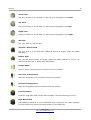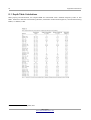
1
OKM
Gepard GPR
Ground Penetrating Radar
User's Manual
3D
Any information contained in these operating instructions may be changed without prior notice.
OKM does not make any warranty for this document. This also applies without limitation to implied assurances of
merchantability and fitness for a specific purpose. OKM does not assume any responsability for errors in this manual
or for any incidental or consequential damage or loss associated with the delivery, exploitation or usage of this
material.
This documentation is available "as presented" and without any kind of warranty. In no circumstances OKM takes
responsibility for lost profits, usage or data losts, interruption of business activities or all kind of other indirectly
damages, which developed because of errors in this documentation. This instruction manual and all other stored
media, which are delivered with this package should only be used for this product. Program copies are allowed only
for security- and safety purposes. The resale of these programs, in original or changed form, is absolutely forbidden.
This manual may not be copied, duplicated or translated into another language, neither in part nor completely, over
the copyright matters without the prior written consent of OKM.
Copyright ©2013 – 2015 OKM GmbH. All rights reserved.
3
Table of Contents
1 Introduction ........................................................................................................................................... 7
1.1 Preface ........................................................................................................................................... 8
1.2 Important Notes ............................................................................................................................. 9
1.2.1 General Notes ........................................................................................................................ 9
1.2.2 Possible Health Hazards ......................................................................................................... 9
1.2.3 Surrounding Area ................................................................................................................... 9
1.2.4 Voltage ................................................................................................................................... 9
1.2.5 Data safety ........................................................................................................................... 10
1.3 Maintenance and Services ........................................................................................................... 10
1.4 Danger of Explosion during Excavation ....................................................................................... 10
2 Technical Specifications ....................................................................................................................... 13
2.1 Control Unit ................................................................................................................................. 14
2.2 Data Transmission ........................................................................................................................ 14
3 Scope of Delivery ................................................................................................................................. 15
4 Control Elements ................................................................................................................................. 19
4.1 Control Unit ................................................................................................................................. 20
4.1.1 Front View ............................................................................................................................ 20
4.2 Headphones ................................................................................................................................. 21
4.3 Tablet holder ................................................................................................................................ 22
5 Assembly .............................................................................................................................................. 23
5.1 Mounting the antennas ................................................................................................................ 25
5.1.1 Telescopic antennas ............................................................................................................. 25
5.1.2 Triangular antennas ............................................................................................................. 26
5.2 Mounting the Tablet PC ............................................................................................................... 27
6 Field procedure .................................................................................................................................... 29
6.1 Adjusting the GPR antennas ......................................................................................................... 30
6.1.1 Telescopic Antennas ............................................................................................................. 30
6.1.2 Triangular antennas ............................................................................................................. 31
6.2 Conducting a field measurement ................................................................................................. 31
7 Software ............................................................................................................................................... 33
7.1 New Scan ..................................................................................................................................... 35
7.1.1 Concucting a measurement in 2D ........................................................................................ 39
7.1.2 Concucting a measurement in 3D ........................................................................................ 39
7.2 View Scan ..................................................................................................................................... 40
7.2.1 Action bar (menu) ................................................................................................................. 40
7.2.2 Applying filters ..................................................................................................................... 41
7.2.3 Changing project title and notes .......................................................................................... 42
7.2.4 Setting field dimensions ....................................................................................................... 43
OKM GmbH
www.okmmetaldetectors.com
4
7.2.5 Viewing a 2D measurement ..................................................................................................
7.2.5.1 Soil Types and Color Schemas .....................................................................................
7.2.5.2 Toolbar ........................................................................................................................
7.2.5.3 Sidebar ........................................................................................................................
7.2.5.4 Crosshairs ...................................................................................................................
7.2.5.5 Statusbar .....................................................................................................................
7.2.5.6 Scrollbar ......................................................................................................................
44
44
44
45
45
45
45
7.2.6 Viewing a 3D measurement ..................................................................................................
7.2.6.1 Soil Types and Color Schemas .....................................................................................
7.2.6.2 Toolbar ........................................................................................................................
7.2.6.3 Sidebar ........................................................................................................................
7.2.6.4 Statusbar .....................................................................................................................
46
46
46
48
48
7.3 Activation ..................................................................................................................................... 48
8 Appendix & References ........................................................................................................................ 51
8.1 Depth Table Calculations ............................................................................................................. 52
OKM GmbH
www.okmmetaldetectors.com
5
Illustration Index
Figure 4.1: Front view of control unit ..................................................................................... 20
Figure 4.2: Charging Port and LED Indicator ......................................................................... 21
Figure 4.3: Control elements of wireless headphones ............................................................ 21
Figure 4.4: Elements of the tablet holder ............................................................................... 22
Figure 5.1: Main Unit with extended battery housings ........................................................... 24
Figure 5.2: Line up the shafts ................................................................................................. 24
Figure 5.3: Push together the shafts and match the colors .................................................... 24
Figure 5.4: Connect the BNC to control unit .......................................................................... 24
Figure 5.5: Attach extendable antenna to shaft ...................................................................... 25
Figure 5.6: Tighten antenna by turning clockwise .................................................................. 25
Figure 5.7: Package contents of triangular antennas ............................................................. 26
Figure 5.8: Mounting the triangular antennas ........................................................................ 26
Figure 5.9: Gepard GPR with mounted triangular antennas ................................................... 27
Figure 5.10: Mount the Tablet PC to the tablet holder ........................................................... 27
Figure 5.11: Attach the monitor to the main unit ................................................................... 28
Figure 6.1: Example of antenna extensions and depth capabilities ........................................ 31
Figure 6.2: Holding the Gepard GPR before starting the scan ............................................... 32
Figure 7.1: Main application menu ......................................................................................... 34
Figure 7.2: New Scan - Enter project title .............................................................................. 35
Figure 7.3: New Scan - Scan Mode ......................................................................................... 35
Figure 7.4: New Scan - Antenna Selection .............................................................................. 36
Figure 7.5: New Scan – Field Dimensions ............................................................................... 36
Figure 7.6: New Scan – Apply settings to your Gepard GPR ................................................... 37
Figure 7.7: New Scan – Single line only (2D) or multiple lines from right to left (3D) ........... 38
Figure 7.8: Conducting a measurement after Bluetooth connection is established ................ 38
Figure 7.9: View Scan – List of measurements ....................................................................... 40
Figure 7.10: Filter dialog ........................................................................................................ 41
Figure 7.11: Notes dialog ........................................................................................................ 42
Figure 7.12: Field dimensions dialog ...................................................................................... 43
Figure 7.13: Overview of 2D screen ........................................................................................ 44
Figure 7.14: Overview of 3D screen ........................................................................................ 46
Figure 7.15: Activation – Welcome Screen .............................................................................. 49
Figure 7.16: Activation – Entering the serial number ............................................................. 49
Figure 7.17: Activation – Entering the activation code ........................................................... 50
Figure 8.1: Dielectric reference for various soil attenuation .................................................. 52
OKM GmbH
www.okmmetaldetectors.com
1 Introduction
CHAPTER 1
Introduction
8
Introduction
1.1 Preface
Dear Customer,
all of the engineers, sales, training and support staff at OKM GmbH would like to thank you for your
purchase of the Gepard GPR.
The Gepard GPR detector works on the principle of Ground Penetrating Radar (GPR). The radar ( RAdio
Detection And Ranging) sends a signal into the ground and awaits the reflection of the electrical signal
or in common terms an “echo” of the signal to detect sub-surface anomalies. Besides the detection of
metallic objects, this device is also capable of detecting natural features of the earth like formations of
strata, cavities, voids, faults, and other non-metallic objects. This equipment is best suited at detecting
sub-surface anomalies like, sepulchers, buried treasure, buried utilities, tanks and the like.
The Gepard GPR is able to locate, document and analyze buried objects within various soil conditions,
structures and vessels non-intrusively without having to excavate the area. Using the GPR is particularly
useful in areas where detection is a must and excavation is not possible. The easy and flexible handling
of the Gepard GPR can easily and quickly give reproducible results.
With our team of specialists we guarantee that our products are under recurrent control. Our specialists
are constantly striving to improve the equipment, performance and understanding of the equipment.
By purchasing or using one of our products, we cannot guarantee that during your research you will be
successful and have a find. The recognition of hidden and buried objects depends on a huge number of
factors. As you well may know there are different soil types all over the world with different levels of
natural attenuation. Variable soil properties can and will hamper and alter ultimate scan measurements.
Areas where there is an extreme amount of ground water, varying clays, sands and wet soils making
scanning more difficult and may reduce the maximum depth capabilities of any and all detection
equipment, regardless of make or model.
For more information regarding where this equipment has been used, operated and tested, please visit
our website or contact a sales representative. Our equipment is under constant testing and
improvement. With this being mentioned, it is possible for material in this handbook to change without
notice.
It is necessary for our company to protect our developments and all the information learned during the
“Research and Development” phases in creating our technology. We strive to stay within the given
framework of legislation, patents and trademark registration.
Please take the time to read this User Manual and familiarize yourself with the operation, functionality
and how to utilize the Gepard GPR. We also offer training for your equipment in our factory and on-site.
We strive to maintain a worldwide dealer network for assistance and support. Please visit our web site
for more information.
OKM GmbH
www.okmmetaldetectors.com
Introduction
9
1.2 Important Notes
Prior to using the Gepard GPR and its accessories, please read these operating instructions carefully.
These instructions give information on how to use the detector and potential sources where precautions
should be taken.
The Gepard GPR and its accessories serve for the analysis, documentation and detection of sub-surface
anomalies and ground disturbances. The recorded data of the ground structure will be transmitted to an
electronic device like an Android PC to give a visual representation of the anomaly. Using our
proprietary software program will assist in visualizing the object.
1.2.1 General Notes
Being an electronic device, the Gepard GPR has to be treated with caution and treated with care as with
all other electronic devices. Any failure to observe safety precautions or use of the equipment for
purposes other than its intended design may result in damage or destruction of the processing unit
and/or its accessories or connected components.
The device has a built in anti-tampering module which will destroy the unit if it is improperly opened.
There are no end user serviceable parts on the inside of the unit.
1.2.2 Possible Health Hazards
If used properly this device normally does not pose any health hazards. According to current scientific
knowledge, the high-frequency signals are not harmful to the human body on account of their very low
power.
1.2.3 Surrounding Area
When moving this unit from a cold place to a warmer place, watch out for condensation. Do not
immediately operate the unit until any possible condensation could have evaporated. The unit is not
weather proof and water or condensation can destroy the unit.
Avoid strong magnetic fields, which may occur in places where there are large electric motors or
unshielded loudspeakers. Try to avoid using this equipment within 50 meters (150 ft) of this type of
equipment.
Metallic objects on the ground such as cans, tin, nails, screws or debris can influence your scan data and
present negative results regarding your scan data. Also it is a good habit to remove any metallic objects
off of your person like cellular telephones, keys, jewelry, etc... Do not wear steel toe boots.
1.2.4 Voltage
Please be aware that the unit is battery powered.
Please use only approved batteries and power
supplies for this unit.
Never connect or use a 115/230 Volt main AC power supply!
OKM GmbH
www.okmmetaldetectors.com
10
Introduction
1.2.5 Data safety
Data errors can occur if:
•
the range of the sender module has been exceeded,
•
the power supply of the device or the batteries are too low,
•
the antenna is not extended far enough or extended too far,
•
the unit is operating to close to devices which sends out or causes disturbances
•
atmospheric conditions (electrical storms, lightning, etc...)
1.3 Maintenance and Services
In this section you will learn how to maintain your measuring instrument with all included accessories to
keep it in good condition for a long time and to get receive measuring results.
The following list indicates what you absolutely should avoid:
•
penetrating water
•
strong dirt, sand and dust deposits
•
hard impacts or drops
•
strong magnetic fields
•
operating within metal enclosures
•
continued exposure to high heat
To clean your device please use a dry soft rag or cloth. To avoid any damage you should transport the
device and accessories always in the appropriate carrying case(s).
Prior to using your Gepard GPR please be sure that all batteries and accumulators are fully charged.
To charge the external and internal batteries, use only the approved chargers which are part of
our scope of delivery.
1.4 Danger of Explosion during Excavation
Unfortunately, the last two world wars and other conflicts have also made the ground in many places of
the world a potentially explosive scrap heap. A host of those lethal relics are still buried in the ground.
Do not start digging and hacking for an object wildly when you receive a signal of a piece of metal from
your device. Firstly, you might indeed cause irreparable damage to a truly rare find, and secondly, there
is a chance that the object reacts in an insulted way and strikes back.
Note the color of the ground close to the surface. A red or reddish color of the ground is an indicator of
rust traces. As regards the finds themselves, you should definitely pay attention to their shape. Curved
or round objects should be a sign of alarm, especially if buttons, rings or little pegs can be identified or
OKM GmbH
www.okmmetaldetectors.com
Introduction
11
felt. The same applies to recognizable ammunition or bullets and shells. Leave that stuff where it is, do
not touch anything and, most importantly, do not take any of it home with you. The killing machines of
past wars have made use of diabolical inventions such as rocker fuses, acid fuses and ball fuses. Those
components have been rusting away in the course of time, and the slightest movement may cause parts
of them to break and be triggered. Even seemingly harmless objects such as cartridges or larger
munitions are anything but that. Explosives may have become crystalline over time, that is, sugar-like
crystals have formed.
Moving such an object may cause those crystals to produce friction, leading to an explosion. If you come
across such relics, mark the place and do not fail to report the find to the police. Such objects always
pose a danger to the life of hikers, walkers, farmers, children and animals.
OKM GmbH
www.okmmetaldetectors.com
2 Technical Specifications
CHAPTER 2
Technical Specifications
14
Technical Specifications
The following technical indications are medial values. During operation small variations are quite
possible.
2.1 Control Unit
Dimensions (H x W x D) ................................................................................................ 350 x 182 x 60 mm
Weight (without batteries)...................................................................................................... about 1700 g
Voltage ....................................................................................................................... 9.6 – 13.2 VDC, 18 W
Operating Time (alkaline batteries, 25 °C) ........................................................................... about 6 hours
Operating Time (accumulator batteries, 25 °C) .................................................................... about 3 hours
Operating Time (OKM Power Pack 25 °C) ........................................................................... about 10 hours
Operating Temperature .................................................................................................... -20 °C to +55 °C
Storage temperature ........................................................................................................ -25 °C to +60 °C
Air humidity ............................................................................................................................... 5 % – 70 %
Battery Charger Module ................................................................................................................. Internal
External Power Supply .......................................................................................................... Yes (optional)
Waterproof ............................................................................................................................................. No
Multiple Transmission Frequency Range .................................................................... 60 MHz to 300 MHz
Control Display .................................................................................................................................... LED
Multi-Function Control .......................................................................................................................... Yes
Timing/Sampling Adjustments Send/Receive ............................................................................... 16 Levels
Complete Cycle Measurements .............................................................................................. 9 per second
2.2 Data Transmission
Technology .................................................................................................................................. Bluetooth
Transmission Frequency ......................................................................... ISM band from 2400–2480 MHz
OKM GmbH
www.okmmetaldetectors.com
3 Scope of Delivery
CHAPTER 3
Scope of Delivery
In the following section is a detailed list of all standard equipment shipped with the Gepard GPR. In
some instances the contents may vary depending on custom configurations from the customer.
16
Scope of Delivery
Description
Quantity
Control Unit
1
Battery Housing (4 x AA (LR6)
Battery)
2
Extendable Telescopic Antenna
(including Spare Antenna)
6
Shaft with Transmitter
(Red bands on BNC connector)
2
Image
Shaft with Receiver
(Black bands on BNC connector)
Charger and travel adapter
1
Android Tablet
1
Android Tablet Holder
1
User Manual
1
OKM GmbH
www.okmmetaldetectors.com
This Book
Scope of Delivery
17
Description
Quantity
Wireless Headphones
1
Water and Shock Resistant Peli Case
1
Triangular Antennas (including
transmitter and receiver)
4
Table 1: Gepard Packing List
OKM GmbH
www.okmmetaldetectors.com
Image
4 Control Elements
CHAPTER 4
Control Elements
In this section you will learn more about the fundamental use of all control elements for the Gepard GPR
measuring instrument. All connections, inputs and outputs are explained in detail.
20
Control Elements
4.1 Control Unit
The control unit is the processing center of the Gepard GPR. It's collecting data from the underground
and sending it to the Android Tablet PC.
4.1.1 Front View
In figure 4.1 the front view of the control unit is shown.
Start/Stop button
Red LED
Green LED
Yellow LED
Depth Regulator
Depth regulator
Connector for
transmitting antenna
Battery compartments
Connector for
receiving antenna
Figure 4.1: Front view of control unit
The main unit controls are very simple. Primarily there are two controls on the main unit. The start/stop
button and the depth regulator. The start/stop button is the main control for turning on the unit,
starting, stopping and turning off the unit.
To turn on the Gepard GPR, simply press the start/stop button one time. The unit will turn on and as a
test all three of the LEDs will illuminate for approximately 3 seconds, then will turn off for internal
testing for the next 5 seconds. After approximately 8 seconds, the red LED (= no measurement in
progress) and the green LED (= ready for sampling) will illuminate. During the startup period or until
the red and green LEDs are illuminated, do not press the start/stop button.
The Gepard GPR can be operated from either internal or external batteries. The optional OKM Power
Pack can also power the unit. This external power pack, when connected, can operate the unit and
charge internal rechargeable batteries.
OKM GmbH
www.okmmetaldetectors.com
Control Elements
21
Battery charging port
Battery charging LED
Figure 4.2: Charging Port and LED Indicator
In figure 4.2 is shown where to connect the battery charger or the external power supply. When there
are internal rechargeable batteries the battery charging LED will illuminate. In the event that the
internal batteries are not rechargeable, the unit will recognize this and not put a charge to the batteries.
To turn off the Gepard GPR, press and hold the start/stop button for 3 seconds. As you are holding the
button, the red LED will remain illuminated until it is released.
4.2 Headphones
Figure 4.3 shows all control elements of the delivered wireless headphones.
Protective cap
for battery case
Power on/off
button
Volume control
Frequency
regulator
Figure 4.3: Control elements of wireless headphones
To use the delivered wireless headphones, you should insert two fully charged type AAA rechargeable or
alkaline batteries inside the battery case. Remove the battery cover on the left site "L" and insert the
OKM GmbH
www.okmmetaldetectors.com
22
Control Elements
batteries into the battery case. Please make a note to insert the batteries correctly. Now place the
protective cap again on the battery case and press carefully until it snaps into place.
Power on the wireless headphones with the power on/off button (ON/OFF) and find the correct channel
with the frequency regulator (TUNE). The device Gepard GPR should be powered on and release an
acoustic signal during this adjustment.
Via the volume control (VOL) you can regulate the volume of the headphones.
4.3 Tablet holder
The tablet holder is used to mount a Tablet PC on top of the Gepard GPR.
Top Bracket
Clip / Fastener
Bottom Bracket
Figure 4.4: Elements of the tablet holder
Clip/Fastener: Use this clip to loosen or tighten the top bracket of the Table Holder. This bracket will
push the Tablet PC into the bottom bracket to keep it in place. As soon as the Tablet PC is fixed between
the brackets lock the clip.
Top Bracket / Bottom Bracket: These two brackets keep the Tablet PC in place after tighten the Clip.
OKM GmbH
www.okmmetaldetectors.com
Assembly
23
5 Assembly
CHAPTER 5
Assembly
This section explains how to assemble the Gepard GPR and to prepare the unit for operation.
OKM GmbH
www.okmmetaldetectors.com
24
Assembly
Preparing the Gepard GPR for use is very simple. After inspecting all of the components and ensuring
that all parts are present, assembly can begin.
Figure 5.1: Main Unit with extended battery housings
Remove the battery housings from the main unit and insert 8 AA size (LR6; NiMH or Lithium)
rechargeable or alkaline batteries. Inside of the housings, the battery orientation is shown.
When using disposable batteries, do not use Zinc Carbon (Zink-Braunstein) batteries to power
the Gepard GPR.
Insert the battery housings back into the main unit and push in until they lock into place.
Figure 5.2: Line up the shafts
Figure 5.3: Push together the shafts and match the
colors
Match the shaft color to the plug. Red to red and black
to black.
Connect the BNC connectors to the control unit. Line up
the tabs and turn clockwise to tighten and counterclockwise to loosen.
Figure 5.4: Connect the BNC to control unit
OKM GmbH
www.okmmetaldetectors.com
Assembly
25
5.1 Mounting the antennas
There are 2 different types of antennas available, that you can use to conduct a measurement:
•
Telescopic Antennas (standard)
•
Triangular Antennas (advanced)
5.1.1 Telescopic antennas
Connect the extendable telescopic antenna to the lower portion of the transmitting and receiving shafts.
Figure 5.5: Attach extendable antenna to shaft
Figure 5.6: Tighten antenna by turning clockwise
Turning the antenna clockwise will tighten it onto the bottom of the shafts. The extendable telescopic
antennas can be interchanged with either of the shafts.
Prior to storing the unit back in the carrying case, unscrew the extendable antennas. This will help to
prevent any damage to the antennas.
OKM GmbH
www.okmmetaldetectors.com
26
Assembly
5.1.2 Triangular antennas
The triangular antennas come with its own set of transmitter (red) and receiver (black) shafts as well as
its own set of cables.
Figure 5.7: Package contents of triangular antennas
Pull back the metal lock and simply push the transmitter or receiver head over the triangular antenna as
shown in figure 5.8. Then release the metal lock to fix the antenna to the transmitter or receiver head.
Figure 5.8: Mounting the triangular antennas
Now remove the transmitter and receiver shafts of the telescopic antennas from the device and replace
it with the new transmitter and receiver shafts of the triangular antennas.
OKM GmbH
www.okmmetaldetectors.com
Assembly
27
Figure 5.9: Gepard GPR with mounted triangular antennas
Please check that all red indicated parts belong to each other. So the red transmitter needs to be
connected to the red marked side of the Gepard GPR as shown in figure 5.9.
5.2 Mounting the Tablet PC
Insert the Android tablet PC between top and bottom bracket of the tablet holder and fix it by using the
clip/fastener.
Figure 5.10: Mount the Tablet PC to the tablet holder
The holder slides on top of the bracket. To remove, simply lift off.
OKM GmbH
www.okmmetaldetectors.com
28
Assembly
Figure 5.11: Attach the monitor to the main unit
OKM GmbH
www.okmmetaldetectors.com
6 Field procedure
CHAPTER 6
Field procedure
This chapter gives practical instructions about the general procedure of scanning an area. The different
scanning methods and procedures will be explained in detail.
30
Field procedure
The Gepard GPR from the original conception has the design of ease and simplicity allowing for the use
and operation of the unit without needing an extensive amount of training or schooling.
For the use and operation of the Gepard GPR, there are several factors to take into consideration. Many
are very simple some are more complicated. The operation of the unit is simple and using the following
rules will give good consistent data:
1.
During a measurement it is important to keep the transmitting antenna and the receiving
antenna at the same height above the ground.
2.
Do not change the height during a measurement. Usually the distance should be as close to the
ground as possible but in case of obstacles you have to use a bigger distance which must be
maintained during the complete scan.
3.
Do not swing the GPR from the left to the right. Keep the unit steady and in the direction that
you would like to scan.
4.
Move the GPR at a consistent speed, even though it can scan using the GPS coordinates, moving
the unit at the same speed helps in locating your target easier.
5.
If a suspected target is detected, repeat the scan. With any detection device, repeating the
detectable object will increase your accuracy.
The ground, this is going to be your biggest challenge. Though the unit can detect items to depths of
approx. 40 meters, please consider the fact that with so many varying soil types and combinations, there
are some locations where maximum depths will be considerably less.
In the Android Tablet PC, the software has been simplified requiring only a couple of steps prior to
beginning a measurement. In the software section on page 33, we will explain in detail how to begin a
measurement.
Conducting measurements is quite simple. Knowing your starting position and stopping position of every
scan and keeping the scan lines straight will help to localize sub-surface targets. Enabling the GPS in
your Tablet PC will aid in the localization and assist in retracing the path taken. The GPS does not
transmit data, it only receives data and is available in most parts of the planet.
Keeping notes of the measured area are very important. Notes can be written directly into the file (see
section "7.2.3 Changing project title and notes" on page 42).
6.1 Adjusting the GPR antennas
The Gepard GPR does not use a shielded transmission system and transmits in an omni directional
pattern. Be aware when in enclosed spaces that the data being measured may be above as well as below.
6.1.1 Telescopic Antennas
Take the fully assembled unit and extend the antennas. The extension of the antennas will dictate the
frequency as well as the ultimate depth. For smaller items that are very near the surface the antennas
can be shortened which will be able to see nearer to the surface. To see larger items that are deeper,
OKM GmbH
www.okmmetaldetectors.com
Field procedure
31
lengthen the antennas. While setting up a measurement with your Tablet PC the application will also
suggest a preferred antenna setup according to your entered information about the estimated object size
and depth.
Figure 6.1: Example of antenna extensions and depth capabilities
6.1.2 Triangular antennas
Preparing the professional triangular antennas is really easy, because there is no adjustment necessary
at all. You just have to make sure to replace all antennas along with transmitter and receiver.
6.2 Conducting a field measurement
While configuring your measurement with the Tablet's 3d application you may choose between two
different scan modes:
2D Scan
This scan mode is used to scan just one straight single line over your scan
field. So this is very useful to precheck your area for potential anomalies like
pipelines or tunnels.
If the underground object is very large in horizontal dimension you will see
an anomaly by just passing over it one time.
3D Scan
While using the 3D scan mode you have to scan more than just one single
line. You will scan your first straight line and then step to the left side to
scan another line. Simply repeat this procedure several times to collect data
of a complete scan area.
In this way you will be able to determine several underground objects in just
one measurement.
OKM GmbH
www.okmmetaldetectors.com
32
Field procedure
After setting up your software application go to the start point of your first scan line and make sure the
antennas have the same distance to the surface as shown in figure 6.2.
Figure 6.2: Holding the Gepard GPR before starting the scan
More information about setting up the measurement and how to start or stop your lines you will learn in
sections "7.1.1 Concucting a measurement in 2D" and "7.1.2 Concucting a measurement in 3D" starting
on page 39.
OKM GmbH
www.okmmetaldetectors.com
7 Software
CHAPTER 7
Software
The Gepard GPR software is fully explained. How to work the various features and conduct the data
analysis.
34
Software
After starting the Gepard GPR application you will see the main application menu as shown in figure 7.1.
Figure 7.1: Main application menu
In the main menu you can select following options:
•
New Scan
Select this option if you want to create a new measurement whether in 2D or 3D.
•
View Scan
All your measurements are stored automatically on the Tablet PC. Using this option you will be
able to select certain scans for detailed evaluation.
•
Activation
Before using the Gepard GPR for the first time you need to activate your device. The process of
activation starts by selecting this option.
•
Support Info
If you need to contact the manufacturer for help you may use this option.
OKM GmbH
www.okmmetaldetectors.com
Software
35
7.1 New Scan
After selecting this operating mode from the main menu you have to follow several screens to set up
your application according to your specific task.
Figure 7.2: New Scan - Enter project title
In the first screen from figure 7.2 you must enter a project title, which is later on used to find your
measurement from the list of all recorded files (see section 7.2 on page 40).
Figure 7.3: New Scan - Scan Mode
During the next step you have to select the type of measurement. You have 2 choices:
•
2D Scan
The 2D scan is used to scan a single line only. You will just see the reflections of underground
objects in simple 2D graphics.
OKM GmbH
www.okmmetaldetectors.com
36
Software
•
3D Scan
The 3D scan is used to scan many parallel lines to get a real 3D image of the underground
objects.
Figure 7.4: New Scan - Antenna Selection
After selecting the scan mode you have to select one of the available antennas. According to figure 7.4
you may select one of the following options:
•
Telescopic Antenna
Use this option if you have connected the telescopic antennas.
•
Triangular Antenna
Use this option if you have connected the additional triangular antennas.
Figure 7.5: New Scan – Field Dimensions
OKM GmbH
www.okmmetaldetectors.com
Software
37
During the next step, shown in figure 7.5, you will adjust some settings concerning the scan field itself:
•
Field Length
Here you adjust the length of a single scan line. For a 3D scan each single scan line has the same
length. If "Automatic" is selected the final length of the line is determined during the scan of the
first line of a measurement.
•
Soil Type
Selecting the correct soil type will make the depth measurements of the Gepard GPR very close
to actual. Due to the fact that there are literally millions of various combinations of soils, getting
the exact one will not always be possible.
Various soil types will have different attenuation factors. Soil magnetic permeability (detailed
table located on page 52) is the ability for electrical signals to travel through different media. As
a geological note, allows the radar wave to travel through the earth and return with an echo.
One of the best ways to determine the proper soil type in an area is to conduct a measurement
over a known buried object at a known depth. Conduct the scan and then compare the soil type
to the depth of the object. This is a quick and easy method to determine the best soil for the
area.
•
Maximum Depth
The indicated depth will be the maximum depth to which the Gepard GPR is measuring into the
underground (according to your selected soil type). The smaller the depth the better the
resolution of objects that are closer to the surface. For greater depths the resolution will
decrease. It is essential that the proper soil type has been selected before.
In case you have selected the telescopic antennas you will have one more option to adjust:
•
Object Size
According to the object size you have to adjust your telescopic antennas. This is some helper
function to make it easier for you to extend your telescopic antennas in the right way.
After all the previous steps has been processed successfully you will see the screen from figure 7.6.
Figure 7.6: New Scan – Apply settings to your Gepard GPR
Depending on your settings you will see how to prepare your Gepard GPR for the upcoming
measurement:
OKM GmbH
www.okmmetaldetectors.com
38
Software
•
Regulator position
This value indicates on which position you have to adjust the depth regulator of your Gepard
GPR. Additionally you will see a figure of the correct adjustment.
•
Antenna segments
This value indicates how many segments of your telescopic antenna should be extended.
Additionally you will see a figure of the correct adjustment. This information is not available if
you have selected the triangular antenna.
Another information that you can find on this screen is how to walk the scan field. Just a straight single
line for 2D scans (figure 7.7 left) or multiple straight lines next to each other starting from right to left
for 3D scans (figure 7.7 right).
Figure 7.7: New Scan – Single line only (2D) or multiple lines from right to left (3D)
Before tapping on "Start" you have to power on your Gepard GPR and prepare your depth regulator as
well as the antennas if necessary.
After tapping on "Start" you will see the screen from figure 7.8. Now the application establishes a
Bluetooth connection between Tablet PC and Gepard GPR. If the connection has been established
properly the Gepard GPR's orange LED switches on.
Figure 7.8: Conducting a measurement after Bluetooth connection is established
OKM GmbH
www.okmmetaldetectors.com
Software
39
According to the selected scan mode you can now conduct your measurement.
7.1.1 Concucting a measurement in 2D
For a simple 2D scan you just have to walk a single but straight line.
Go to your start point, the antennas should be 10 cm above the ground, and push the start/stop button
on your Gepard GPR. Then keep walking slowly and continously to the end point of your scan line. As
soon as you reach the end point push the button again to stop the scan.
During this process you should see the data appearing on the screen of your Tablet PC.
Tap this button to finish the 2D scan and answer the upcoming message with "Yes".
7.1.2 Concucting a measurement in 3D
For a 3D scan you have to walk multiple straight lines while starting on the right side of your scan field.
Each additional scan line is made left to the previous one.
Go to your start point, the antennas should be 10 cm above the ground, and push the start/stop button
on your Gepard GPR. Then keep walking slowly and continously to the end point of your scan line.
Depending on your selection of the field length one of the following actions is necessary:
Field Length = Automatic
Field Length ≠ Automatic
As soon as you reach the end point of the first
After reading enough values the Gepard GPR
scan line push the button again to stop the line.
will stop automatically.
By that you also set the final length of each
following scan line.
Now go back to the start point of your first scan line and step to the left. Repeat scanning the next line
by pushing the start/stop button. From now on the Gepard GPR will stop automatically at the end of the
line.
Repeat the process for as many lines as necessary to complete your whole scan.
Tap this button to finish the 3D scan and answer the upcoming message with "Yes".
OKM GmbH
www.okmmetaldetectors.com
40
Software
7.2 View Scan
After conducting several measurements you can open and evaluate your scans in more detail. Therefor
you select the option "View Scan" from the main menu. Now you can see a list of available
measurements as shown in figure 7.9.
Figure 7.9: View Scan – List of measurements
Tapping on one of the entries will just open the measurement. Tapping and holding for a longer while a
popup list will appear with further actions:
•
View
This option will open the measurement in the scan mode it was recorded in. So 2D scans will be
shown in 2D and 3D scans will be shown in 3D.
•
View in 2D
This option is only useful for 3D scans. So 3D scans will be shown in 2D only by just adding the
single scan lines one after another.
•
Delete
Use this option to delete the file from the memory. After deleting the file the scan is not
recoverable.
7.2.1 Action bar (menu)
Depending on the model of your Tablet PC there are two ways to popup the action bar or menu:
1.
Your Tablet PC is equipped with a real hardware menu button (symbolyzed by a bended arrow at
the bottom frame of your tablet) that you can tap to open the menu.
2.
Your Tablet PC has no hardware menu button but a software action bar (symbolized by three
square dots at the top action bar) to open the menu.
No matter how you are opening the menu, you will see following items:
OKM GmbH
www.okmmetaldetectors.com
Software
•
41
Filter ...
This option can be used to change the applied filter settings. This is only recommended for
professional users. Changing the settings can result in wrong data display.
•
Notes ...
Use this option to change the project title and add additional remarks to your measurement.
•
Field Dimensions ...
This option is used to enter the correct field dimensions of your measurement.
•
Meters
Select this option to change all units into meters (m).
•
Feet
Select this option to change all units into feet (ft).
The last two options (Meters, Feet) are available throughout the complete Gepard GPR application. So
you can change the unit system at any time where necessary.
The first three options will be explained in more detail in the following sections.
7.2.2 Applying filters
After opening a 3D measurement the default filter is applied automatically to improve the visual
representation of your recorded data. For all 2D measurements no filter is applied at the beginning, but
you can do so manually if necessary.
To apply the filters or change the settings accordingly you need to open the menu and select the option
"Filter ...". Then the dialog from figure 7.10 appears on screen.
Figure 7.10: Filter dialog
The following settings are available:
•
High-Pass Filter
The High-pass filter is used to remove lower frequencies that may disturb your measurement. So
your preferred frequencies will stay in place to indicate underground anomalies.
OKM GmbH
www.okmmetaldetectors.com
42
Software
•
Input Filter
The input filter is used to improve the incoming data with better contrast and to remove noisy
background signals. Therefor two values can be adjusted:
◦
Signal Amplification
Enter a value from 0 to 1 to amplify the incoming signals by 0% to 100%.
◦
Noise Suppression
Enter a value from 0 to 1 to reduce the background by 0% to 100%.
•
Envelope Filter
The envelope filter takes a high-frequency signal as input and provides an output which is the
envelope of the original signal. Therefor two values can be adjusted:
◦
Raise Time
Enter a value from 0 to 1 to set the increasing speed of the envelope.
◦
Falloff Time
Enter a value from 0 to 1 to set the decreasing speed of the envelope.
•
Interpolation
The interpolation collects nearby data to form groups of potential structures. Therefor two
values can be adjusted:
◦
Iterations
Enter a value from 1 to 7 to define how often the interpolation process should be executed
over the measurement. The more cycles you run the smoother the result but you may lose
small single objects.
◦
Range
Enter a value from 1 to 19 to set the range or distance of neighbour values that should be
part of the interpolation process.
Depending on the selected checkmarks more or less filters can be applied to your measurement.
7.2.3 Changing project title and notes
Before you create a new measurement you have to enter a meaningful project title. Without entering a
title you cannot conduct a measurement. You may change this project title and your additional remarks
afterwards, e.g. to add some more important information or to precise the current title.
OKM GmbH
www.okmmetaldetectors.com
Figure 7.11: Notes dialog
Software
43
To open the dialog from figure 7.11 you have to select the option "Notes ..." from the popup menu.
7.2.4 Setting field dimensions
If you want to measure the position of possible targets you must enter the correct field dimensions of
your scan area. In the popup menu you have to select the option "Field Dimensions ...". Then the dialog
from figure 7.12 appears on screen.
Figure 7.12: Field dimensions dialog
Now enter the following information:
•
Field Length
This is the length of a single scan line, no matter if you conducted a scan in 2D or 3D.
•
Field Width
This is only useful for 3D scans and indicates the distance between first and last scan line.
To find the correct position on your scan field you have to place the position markers over the detected
object.
OKM GmbH
www.okmmetaldetectors.com
44
Software
7.2.5 Viewing a 2D measurement
In figure 7.13 you see a breakdown of the 2D screen.
Soil Types
Color Schemas
Toolbar
Crosshairs
Sidebar
Scrollbar
Statusbar
Figure 7.13: Overview of 2D screen
Next to the main viewing area there are some elements to control the rendering of the measurement.
7.2.5.1 Soil Types and Color Schemas
By selecting the correct soil type of your scan area you will get better results concerning the depth
measurement. It does not change any visual representation of your gaphic.
Switching between different color schemas can sometimes reveal hidden structures because of different
contrast and brightness settings. So there is no recommended color schema to use, you always have to
find the best solution by yourself.
7.2.5.2 Toolbar
The toolbar is home of several buttons which are explained here:
Google Maps
Open a map to see where your current scan was coducted.
Screenshot
In case you want to save your current view into an image file simply use this
OKM GmbH
www.okmmetaldetectors.com
Software
45
button to create a screenshot of your screen.
7.2.5.3 Sidebar
The sidebar just represents a depth chart to quickly check the approximiate depth of potential objects
and structures. If you would like to get a more specific depth measurement you have to use the
crosshairs.
7.2.5.4 Crosshairs
To read the depth as well as the position of detected objects you just need to move your finger over the
main viewing area to place your crosshairs directly over the potential object. Then you can read the
depth and position value in the statusbar of the screen.
7.2.5.5 Statusbar
The information from the statusbar are mostly based on the position of the crosshairs. So by changing
the crosshairs, the values in the statusbar will also change.
7.2.5.6 Scrollbar
If the visual representation of your measurement is too large to fits on your screen, you may use the
scrollbar to move the graphic left or right.
OKM GmbH
www.okmmetaldetectors.com
46
Software
7.2.6 Viewing a 3D measurement
In figure Fehler: Referenz nicht gefunden you see a breakdown of the 3D screen.
Soil Types
Color Schemas
Toolbar
Sidebar
Statusbar
Figure 7.14: Overview of 3D screen
Next to the main viewing area there are some elements to control the rendering of the measurement.
7.2.6.1 Soil Types and Color Schemas
By selecting the correct soil type of your scan area you will get better results concerning the depth
measurement. It does not change any visual representation of your gaphic.
Switching between different color schemas can sometimes reveal hidden structures because of different
contrast and brightness settings. So there is no recommended color schema to use, you always have to
find the best solution by yourself.
7.2.6.2 Toolbar
The toolbar is home of several buttons which are explained here:
Perspective View
Set your rotation to a perspective view that you will see your 3d graphic from
front, right and top.
OKM GmbH
www.okmmetaldetectors.com
Software
47
Front View
Set your rotation to a view that you will see your 3d graphic from front.
Top View
Set your rotation to a view that you will see your 3d graphic from top.
Right View
Set your rotation to a view that you will see your 3d graphic from right.
3D View
See your data in a full 3d view.
3D View / Planes View
See your data in a 3d view with additional planes as length, width and depth
indicators.
Planes View
You just see simple planes as length, width and depth indicators. So you can
check each scan line or depth level individually.
Google Maps
Open a map to see where your current scan was coducted.
Decrease Transparency
Make the 3d graphic less transparent and more opaque.
Increase Transparency
Make the 3d graphic more transparent and less opaque.
Low Resolution
View the 3d graphic with just the data samples conducted during your scan.
High Resolution
Add additional samples to your conducted scan to improve the object visibility.
This will need much more calculation power of your Tablet PC.
OKM GmbH
www.okmmetaldetectors.com
48
Software
Screenshot
In case you want to save your current view into an image file simply use this
button to create a screenshot of your screen.
7.2.6.3 Sidebar
The sidebar contains some buttons to control the 3d crosshairs, which are visible in one of the plane
view modes.
Move Line
Move the line marker forth and back to measure the width position (if
field dimensions has been set). The line marker is only visible in any
plane view mode.
Move Impulse
Move the impulse marker forth and back to measure the length
position (if field dimensions has been set). The impulse marker is only
visible in any plane view mode.
Move Depth
Move the depth marker forth and back to measure the depth
(depends on selected soil type). The depth marker is only visible in
any plane view mode.
7.2.6.4 Statusbar
The information from the statusbar are mostly based on the position of the crosshairs. So by changing
the crosshairs, the values in the statusbar will also change.
7.3 Activation
When you ordered your Gepard GPR together with an Android Tablet PC, your application is already
activated. In the event that you replace the Android Tablet PC, the following instructions explain how to
activate the software.
In the very front of the user's manual there is a small notice (leaflet). This notice has the
software code for renewing the activation of the software. The leaflet is attached to the inside of
the user's manual. Please make a copy of it and keep it in a safe place.
After selecting the option "Activation" from the main menu you will see the activation screen as
displayed in figure 7.15.
OKM GmbH
www.okmmetaldetectors.com
Software
49
Figure 7.15: Activation – Welcome Screen
After tapping the button "Continue", enter the unit's serial number, as shown in figure 7.16. You will find
your serial number on the notice in front of your user's manual as well as on your device itself. After
entering the right number click the checkmark button to continue.
Figure 7.16: Activation – Entering the serial number
In the next step you will be asked to enter the activation code as shown in figure 7.17. This information
is also printed in the small leaflet in front of your manual. After entering the activation code click the
checkmark button again.
OKM GmbH
www.okmmetaldetectors.com
50
Software
Figure 7.17: Activation – Entering the activation code
Once that is completed and all information are valid you will receive a window stating “Success” and
your software is ready to use.
OKM GmbH
www.okmmetaldetectors.com
8 Appendix & References
CHAPTER 8
Appendix & References
In this chapter you will find appendices to tables and references used.
52
Appendix & References
8.1 Depth Table Calculations
With varying soil attenuation, the Gepard GPR was calculated with a median frequency value of 100
MHz.1 Reference material used from DJ Daniels, Institution of Electrical Engineers, Ground Penetrating
Radar, 2nd Edition, 1996.
Figure 8.1: Dielectric reference for various soil attenuation
1
DJ Daniels, Ground Penetrating Radar, 2004
OKM GmbH
www.okmmetaldetectors.com