1
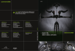
owner’s manual
2013 yeti big top
YETI CYCLES
600 Corporate Circle, Unit D
Golden, CO 80401
888.576.9384
www.yeticycles.com
Table of Contents
Brand Overview
06
Frame Features
08
Geometery
10
Maintenance Schedule
12
setup
cable setup
14
technical
dropout Overview
16
chip system
17
single speed dropouts
18
legal
4.
Warranty
20
Contact Information
21
5.
Welcome to the tribe.
Congratulations on your
purchase of a new Yeti.
We are confident your new bicycle will exceed
your expectations for value, performance, and
ride quality. Each frameset and component
has been custom specified and designed to
enhance your riding experience. Whether you
are a beginner cyclist, or a seasoned pro,
your Yeti bicycle will provide endless hours of
two-wheeled fun.
This manual outlines basic setup and
maintenance recommendations of your new
Yeti. Because it is impossible to anticipate
every situation or condition that may occur
during the assembly, setup, and maintenance
of your bicycle, Yeti recommends that all
service and repairs be performed by your
local authorized Yeti Dealer.
This model specific manual is designed to
be used in conjunction with the general Yeti
Owner’s Manual and the manuals supplied by
the suspension manufactures. If you did not
receive the Yeti owner’s manual or the manual
provided by the suspension manufacturer
download the materials off the Internet, or
contact your local dealer.
This manual contains many “Warnings” and
“Cautions” concerning the consequences
of failure to maintain or inspect your bicycle.
The word “Warning” indicates a potentially
hazardous situation in which , if not avoided,
could result in serious injury or death. The
word “Caution” indicates a potentially
hazardous situation in which, if not avoided
may result in minor injuries or damage to
your bicycle or a component of your bicycle.
Be sure to read and understand all of the
Warnings and Cautions listed in the manual. Bicycling can be a hazardous activity
even under the best of circumstances.
Proper maintenance of your bicycle is your
responsibility and when done properly helps
reduce the risk of injury and damage to your
bicycle.
Warning: Make sure you review and understand the warnings, instructions, and content of this manual and accompanying
manuals for your bicycle. Warning: Technological advances have made bicycles and bicycle components more complex and the pace of innovation is
increasing. It is impossible for this manual or the accompanying manuals to provide all the information required to properly
repair and/or maintain your bicycle. In order to help minimize the chances of an injury, it is critical for you to have work
performed by an authorized Yeti retailer.
6.
7.
A 29’R hardtail with
a true yeti feel.
1.
yeti pure tubing
2.
ISCG 05’ Mount
3.
carbon fiber rear triangle
4.
Tapered Inset HeadTube (44mm/56mm)
5.
direct mount front derailleur
6.
Dropouts 12mm x 142 thru axle or 135mm QR
7.
single speed compatible
1.
The Big Top’s front triangle is constructed with custom butted
and tapered 7005 aluminum Yeti pure tubing. This makes the
frame lightweight and strong without the use of gussets. The
unique shape perfectly compliments the shape of the headtube for
increased front-end stiffness.
2.
Set up and run a 1x10 drivetrain with a chain guide cleanly and
efficiently with the removable ISCG 05’ tab. The tabs are lighter
than a welded version and they are easily removable when running
a traditional 2x10 or 3x10 drivetrain.
3.
The high modulus carbon fiber rear triangle keeps the frame
laterally stiff while providing a more forgiving ride on rougher
terrain.
4.
Using our new inset headtube on the Big Top allows for a larger
headtube with more welding area, increased stiffness, and lower
overall ride height.
5.
Mount a Shimano Direct Mount D Type or Sram High Direct Mount
front derailleur to the Big Top with ease.
6.
The Yeti chip system allows for an easy switch between a standard
135mm QR or the142mm x 12mm Shimano thru-axle system.
7.
Run your Big Top 29’R as a single speed with a set of single speed
drops. The chainstay length is adjustable from 17.3” to 18.0”.
8.
9.
Geometry
100 mm fork
B
I
A
J
D
E
C
K
G
H
F
SM
MD
LG
A
18.0
19.5
21.0
B
23.5
24.8
25.8
C
70.0
70.0
70.0
D
72.0
72.0
72.0
E
17.1
17.1
17.1
F
43.0
44.3
45.3
G
12.0
12.0
12.0
H
31.0
32.0
33.0
I
4.1
4.9
5.5
J
19.7
19.7
19.7
K
1.7
1.7
1.7
*All measurements are in inches
fit
10.
medium
5’7” (170 CM) - 5’10” (178 CM)
large
5’11” (180 CM) - 6’2” (188 CM)
x-large
6’3” (190 CM) - 6’6” (198 CM)
11.
keep your new yeti
fresh and clean
overview
ANNUALLY
3 MONTHS
MONTHLY
schedule
WEEKLY
Following these guidelines will help maintain the performance of your bicycle and prevent
more serious problems from arising. It is important to remember that service intervals can vary
depending on climate, trail conditions and riding frequency. If you are unsure about working on
your own bicycle, contact your authorized Yeti Dealer or visit the repair help section at www.
parktool.com for more information on general bicycle maintenance.
Clean and lube chain
Check tire pressure
Clean bike of mud and debris
Check brake function
Check shock pressure, if applicable
Check for loose bolts and tighten, if necessary
Check headset and tighten / loosen, if necessary
Thoroughly clean pivot points with a rag (do not lubricate)
Replace brake pads, if necessary
Check tires for wear
Check spoke tension and retention, if necessary
Check chain for wear and replace if necessary
Complete tune-up performed by an authorized Yeti dealer
12.
13.
cable Setup
yeti tips
The Big Top has full cable housing. By using full cable housing, we have eliminated break
points in the line of your shifter housing. This allows riders to experience better overall shifting
performance by reducing the entrance of unwanted elements such as sweat and sediment.
Use of full cable housing helps prevent corrosion from the elements and keeps the shifting
smoother for a longer period of time.
Caution: The failure to properly route shifter housing can cause malfunction of the shift mechanism and
unexpected shifting of gears.
14.
02. front derailleur
Fit a piece of housing from the front shifter across the head tube and into the cable stops on the bottom
of the top tube. Fit the front derailleur housing along the three cable stops using the position closest to the
drive side. Next, route the housing down the drive side of the set tube. Run the housing directly into the stop
on the front derailleur to finish.
01. rear derailleur
03. rear brake
Fit the housing from the rear shifter across the head tube and into the cable stops on the bottom of the top
tube. There are three cable stops on the bottom of the top tube, each with three positions to secure housing.
Fit the rear housing line along these stops using the middle position. Next, route the housing down the drive
side seat stay and loop in to the rear derailleur to finish.
The rear brake line loops across the head tube and into the cable stops on the bottom of the top tube. Use
the position closest to the non-drive side of the frame on the cable guides for the rear brake line. Next,
route the brake line down the non-drive side seat stay and into the caliper body. Ensure the line is finished
on the inside of the seatstay when attached to the caliper body. This will prevent the brake line from being
compromised if the bike or rider falls.
15.
dropout systems
yeti tips
tools needed
Make sure your tools are in good condition.
A worn allen key can round the hex on a bolt
not allowing for proper torque.
•5mm allen key
•3mm allen key
•2.5mm allen key
•Blue loctite
Torque settings are listed throughout the
instructions. It is also import to prep all bolt
threads. The instructions denote whether to
use a blue Loctite compound or grease.
Warning: Service on Yeti bicycles requires special knowledge
and tools. Yeti Cycles recommends that all service and
repairs be performed by an authorized Yeti Dealer
01. chip system
02. chip system
Use a 2.5mm allen key to loosen the two
M4x9mm flat head bolts holding the QR insert
derailleur hanger in place. Remove the bolts and
the QR insert from the frame. Repeat the process
for the bolts and the non drive QR insert.
Fit the 12MM insert hanger into the groove on
the inside of the drive side chainstay. The hanger
should be flush with the chainstay. Next, insert
the 12mm drive cap through the chainstay and
into the hanger from the outside of the drive
side chainstay. To finish, use a 3MM allen key to
attach the two dropout pieces to the swingarm
with two M4x15MM cap bolts. Prep the bolts with
loctite and insert them into the drive cap, through
the swingarm and into the hanger.
03. chip system
Fit the 12MM non-drive insert into the groove
on the inside of the non-drive side chainstay.
The insert should be flush with the chainstay.
Next, fit the non-drive 12mm cap through the
chainstay and into the insert from the outside
of the non-drive side chainstay. To finish, use a
2.5MM allen key to attach the two dropout pieces
to the swingarm with two M4x10MM flat head
bolts. Prep the bolts with loctite and insert them
into the non-drive cap, through the swingarm and
into the insert.
04. chip system
Insert the M4x6MM custom cap bolt into the top
of the drive cap. This bolt will be used to set the
position of the Shimano 142x12MM axle. Refer to
Shimano specifications for exact instructions on
proper axle operations.
Torque for all chip system bolts: 15-20 in/lb
16.
17.
dropout systems
18.
dropout systems
01. single speed drops
02. single speed drops
05. single speed drops
06. single speed drops
Use a 5mm allen key to loosen the two
M8x17mm bolts holding the standard drive side
Big Top dropout in place. Remove the bolts and
the dropout from the frame. Repeat the process
for the bolts and drop out on the non-drive side.
Fit a dropout insert into each of the two grooves
on the inside of the drive side single speed drop.
Next, slide the drive side mount over the two
inserts and into the dropout. This assembly fits
flush onto the inside of the drive side chain stay.
Tighten the two M6 shoulder bolts on the drive
side dropout with a 5mm allen key. Repeat the
process for the non-drive side.
Double check that the dropouts are square and
the rear wheel is centered in the frame. When
assembling the Big Top as a single speed for
the first time it will be helpful to set the chain
stay to the desired length before measuring and
cutting the chain. This will help ensure proper
chain tension for the bicycle. When making a
large adjustment of the chain stay length after the
bicycle is assembled be aware that a change to
the chains length may be necessary.
03. single speed drops
04. single speed drops
Attach the assembly from step number two to the
frame with two M6 shoulder bolts prepped with
washers and blue loctite. Use a dropout plate
between the bolts and the outside of the chain
stay. Tighten the bolts so that the dropout can
still slide on the mount, they will be torqued to
spec later in the assembly. Repeat steps two and
three for the non-drive side components.
Place the rear wheel in the dropouts and slide
the drops to the desired chain stay length (17.3”
to 18.0”). Install a M5x50mm cap bolt with a M5
jam nut into each drop out. Adjust these bolts
with a 4mm allen key to ensure both dropouts are
square, the rear wheel is centered in the frame,
and chain tension is correct. Lock the cap bolts
in place by tightening the jam nuts against each
dropout.
Torque to 70-75 in/lb.
19.
Warranty
Yeti Limited (1) ONE Year Frame Warranty
(applies to 303 WC / 4X / DJ)
Yeti Cycles will repair or replace, at its option, any frame it determines to be defective due
to defective materials and/or workmanship. The (1) one year limited warranty is conditioned
upon the bicycle being ridden under normal conditions and having been properly maintained.
This warranty does not apply to the components attached to the frameset such as suspension
components, wheels, drive train, brakes, seatpost, handlebar and stem. This warranty applies
only to the original owner and is non-transferable. This warranty is void if the bicycle was not
properly assembled by an authorized Yeti dealer.
Yeti Limited (2) TWO Year Frame Warranty
(applies to AS-R 5C / AS-R 5A / AS-R Carbon / SB66-A / SB66-C / SB95 / 575 / ARC / Big Top
29’R)
Yeti Cycles will repair or replace, at its option, any frame it determines to be defective due to
defective materials and/or workmanship. The (2) two year limited warranty is conditioned upon
the bicycle being ridden under normal conditions and having been properly maintained. This
warranty does not apply to the components attached to the frameset such as suspension
components, wheels, drive train, brakes, seatpost, handlebar and stem. This warranty applies
only to the original owner and is non-transferable. This warranty is void if the bicycle was not
properly assembled by an authorized Yeti dealer.
No Fault Replacement Policy
Yeti Cycles will make replacement parts available at a minimum charge to the original owner
in the event of a crash or any other non-warranty situation. Yeti Cycles does this at its sole
discretion and reserves the right to refuse this offer.
Product Life Cycle
Every YETI frameset has a useful product life cycle. The length of that useful product life
cycle will vary depending on the construction and the materials of the frameset, maintenance
and care the frameset receives , and the amount and type of use the frameset is subjected to
over its life. YETI recommends that an authorized YETI dealer should inspect the frame for
stress annually. Frame stress could cause potential failure and the signs are usually apparent
in the form of cracks, fracture lines, deformation, dents, and any other visual indicators of
abnormality. These safety checks for frame stress are important to prevent accidents, injury to
the cyclist, and product failure of a YETI frameset.
Disclaimer
YETI Cycles is not responsible for any damages to you or others arising from riding,
transporting or other use of your bicycle. In the event that your frame breaks or malfunctions,
YETI Cycles shall have no liability or obligation beyond the repair or replacement of your frame
pursuant to the terms outlined in the warranty.
*If you have a warranty concern, please contact your authorized Yeti dealer.
Additional Conditions
These limited warranties do not apply to normal wear and tear, nor to claimed defects,
malfunctions or failures that result from abuse, neglect, improper assembly, improper
maintenance, alteration, collision, crash or misuse. The original owner shall pay all labor
charges connected with the repair or removal of all components. Under no circumstance does
this limited warranty include the cost of travel or shipment to and from an authorized Yeti
dealer. In order to exercise your rights under these limited warranties, the bicycle or frameset
must be presented to an authorized Yeti dealer, together with proof of purchase.
*The above warranties have been in effect since January 2012. For warranty information on Yeti
frames sold prior to that date please consult your local authorized dealer.
20.
YETI CYCLES
600 Corporate Circle, Unit D
Golden, CO 80401
(p) 303-278-6909
(f) 303-278-6906
www.yeticycles.com
BUSINESS HOURS
Monday-Friday
8AM-11:30AM, 1:00PM-5:30PM
(Mountain Time)