1
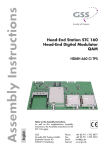
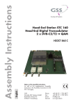
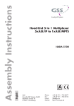
Head-End Digital Modulator HDTV / COFDM KLASSE HDTV 1000 TD English CLASS GSS Grundig SAT Systems GmbH Beuthener Strasse 43 D-90471 Nuremberg Phone: Fax: E-mail: Internet: +49 (0) 911 / 703 8877 +49 (0) 911 / 703 9210 [email protected] http://www.gss.de Contents 1 Safety regulations and notes......................................................................... 4 2 General information..................................................................................... 5 2.1 Packing contents.............................................................................5 2.2 Meaning of the symbols used...........................................................5 2.3 Technical data................................................................................5 2.4 Description....................................................................................6 Input signal path "INROUTE"......................................................7 Menu setting "A+ASI = 1 B+ASI = 2"........................................7 Menu setting "A+B+ASI = 1 ASI = 2"........................................7 Menu setting "A+ASI = 1 A+ASI = 2".......................................7 Output signal path "OUTROUTE"................................................8 Menu setting "ASI => ASI".........................................................8 Menu setting "1 => ASI ASI => MA".........................................8 Menu setting "2 => ASI ASI => MB".........................................8 General...................................................................................9 2.5 Software query..............................................................................9 2.6 How the TPS module works............................................................10 Station filter............................................................................10 Stuffing..................................................................................10 Changing the Transport stream and ORGNET-ID.........................10 Changing the NIT....................................................................10 Changing the operator ID (CAT)................................................10 3 Assembly................................................................................................... 11 3.1 Installing the cassette....................................................................11 3.2 EMC regulations...........................................................................12 3.3 Cassette overview........................................................................13 3.4 Connecting the cassette.................................................................13 3.5 Retrofitting a CA module...............................................................14 4 The control panel at a glance...................................................................... 15 4.1 Menu items..................................................................................15 4.2 Control panel...............................................................................15 5 Programming............................................................................................. 16 5.1 Preparation..................................................................................16 5.2 Notes on level setting....................................................................16 5.3 Programming procedure................................................................17 5.4 Programming the cassette .............................................................20 Selecting the cassette...............................................................20 - 2 - HDTV 1000 TD Input signal path.....................................................................21 Output signal path...................................................................21 ASI transfer rate......................................................................22 ASI options.............................................................................. 22 Selecting the channel strip........................................................23 Channel / frequency setting......................................................23 Output channel.......................................................................24 Output frequency.....................................................................24 Switching the modulator off or on..............................................24 Adjusting the output levels of the channel strips...........................25 LNB oscillator frequency / control voltage..................................26 LNB oscillator frequency...........................................................26 DiSEqC commands..................................................................26 Input symbol rate.....................................................................27 Setting the DVB mode..............................................................27 Input frequency.......................................................................28 Signal to noise ratio.................................................................29 Station filter............................................................................30 COFDM parameters................................................................33 Output signal ............................................................................ 36 Transmission parameters..........................................................37 Transmitter identification...........................................................38 Stuffing..................................................................................38 Setting a substitute signal in the case of an incorrect input signal...39 Transport stream ID and the ORGNET-ID....................................40 Network Information Table (NIT)................................................40 Network/operator identification................................................41 Deleting a PID.........................................................................42 Renaming a PID......................................................................43 Factory reset...........................................................................44 Saving settings........................................................................44 Operation with a CA module.........................................................45 PID monitoring........................................................................45 Configuring the CA module......................................................46 Setting the station filter.............................................................47 6 Final procedures......................................................................................... 49 7 Channel and frequency tables..................................................................... 50 - 3 - HDTV 1000 TD 1 Safety regulations and notes • Assembly, installation and servicing should be carried out by authorised electricians. • Switch off the operating voltage of the system before beginning with assembly or service work or pull out the mains plug. • Do not perform installation and service work during thunderstorms. • Install the system so it will not be able to vibrate… - in a dust-free, dry environment -in such a manner that it is protected from moisture, fumes, splashing water and dampness - somewhere protected from direct sunlight - not within the immediate vicinity of heat sources - in an ambient temperature of 0 °C to +50 °C. In case of the formation of condensation wait until the system is completely dried. • Ensure that the head-end station is adequately ventilated. Do not cover the ventilation slots. • Beware of short circuits • No liability is accepted for any damage caused by faulty connections or inappropriate handling. • Observe the relevant standards, regulations and guidelines on the installation and operation of antenna systems. • The standards EN/DIN EN 50083 resp. IEC/EN/DIN EN 60728 must be observed. • For further information please read the assembly instructions for the headend station used. • Test the software versions of the head-end station and the cassette and update them if necessary. The current software versions can be found at "www.gss.de". Take action to prevent static discharge when working on the device! Electronic devices should never be disposed of in the household rubbish. In accordance with directive 2002/96/EC of the European Parliament and the European Council from January 27, 2003 which addresses old electronic and electrical devices, such devices must be disposed of at a designated collection facility. At the end of its service life, please take your device to one of these public collection facilities for proper disposal. - 4 - HDTV 1000 TD 2 General 2.1 Pac k i n g contents 1 Cassette HDTV 1000 TD 2 Cable terminals 1 Brief assembly instructions 2.2 M e a n i n g 2 RF cables 4 Contact washers o f t h e s ym b o l s u s e d Important note —> General note • Performing works 2.3 T e c h n i c a l information data The devices meet the following EU directives: 2006/95/EC, 2004/108/EC The product fulfils the guidelines and standards for CE labelling (Seite 51). Unless otherwise noted all values are specified as "typical". RF input Frequency range:........................................................ 925 … 2150 MHz Level range:............................................................. 60 dBμV … 80 dBμV DVB-S modes:............................................. QPSK 1/2 , 2/3 , 3/4 , 5/6 , 7/8 DVB-S2 modes:....................QPSK 1/2 , 3/5 , 2/3 , 3/4 , 4/5 , 5/6 , 8/9 , 9/10 8PSK 3/5 , 2/3 , 3/4 , 5/6 , 8/9 , 9/10 Symbol rate DVB-S:........................................... QPSK: 2 … 45 MSymb/s Symbol rate DVB-S2:......................................... QPSK: 10 … 30 MSymb/s 8PSK: 10 … 31 MSymb/s DiSEqC control voltage (sound/DiSEqC)............................. max. 65 mA (switchable) COFDM modulator Signal processing:.......................................................... DIN EN 300744 Transmission modes:................................................................. 2k, 4k, 8k Types of modulation:......................................... QPSK, 16 QAM, 64 QAM Code rates:............................................................. 1/2, 2/3, 3/4, 5/6, 7/8 Guard intervals:.......................................................... 1/4, 1/8, 1/16, 1/32 - 5 - HDTV 1000 TD RF output Frequency range:.............................................. 42.0 MHz … 860.0 MHz Channels:...........................................................C5 … C12, C21 … C69 Types of modulation:......................................... QPSK, 16 QAM, 64 QAM Output level:.............................................................................. 96 dBμV Output impedance:.......................................................................... 75 Ω ASI interfaces Standard:......................................................................DIN EN 50083-9 Format:...............................................................MPEG ISO IEC 13818-1 Maximum data rate:............................................................... 108 Mbit/s Level (input / output):...................................................... 800 mVPP ± 10% Return loss (input):...............................................> 17 dB (5 … 270 MHz) Connections SAT inputs:.............................................................................. 2 F sockets RF output: ............................................................................ 1 IEC socket ASI input:..................................................................1 BNC socket, 75 Ω ASI output:.................................................................1 BNC socket, 75 Ω LAN:................................................................................. 1 RJ-45 socket Connection strip (10-pin):...................for supply voltages and control circuits RS-232 socket:...................................... serial interface for software update Common Interface:............................several channels can be descrambled. Remote maintenance Remotely controllable (via PSW 1000*):............................................... yes Remote update (via BEflash*):.............................................................. yes (* and a corresponding management unit) 2.4 D e s c r i p t i o n The double transmodulator cassette is a converter, which converts all stations modulated according to DVB-S / DVB-S2 standard into two COFDM-modulated signals according to DIN EN 300744 for feeding into a cable network. The cassette has two digital SAT IF inputs and one RF output. Additionally it is equipped with an ASI input and an ASI output (ASI – Asynchronous Serial Interface acc. DIN EN 50083-9). The transport stream fed via the ASI socket can be inserted into the transport streams of the receiving stages via the TPS module. The signal path is set in the menu items input signal path "INROUTE" and output signal path "OUTROUTE". - 6 - HDTV 1000 TD Input s i g n a l pat h Menu setting The transport streams of the receiving stage "TS A" and of the ASI input "TS ASI" generate the transport stream 1. The transport streams of the receiving stage "TS B" and of the ASI input "TS ASI" generate the transport stream 2. RF input ”A“ "INROUTE" "A+ASI = 1 B+ASI = 2" Receiving stage "A" CA module TPS TS ASI ASI input RF input ”B“ TS A Receiving stage "B" Transport stream 1 Transport stream ASI TS B TPS Transport stream 2 Menu The transport streams of the receiving stages "TS A" and "TS B" and of the ASI input "TS ASI" generate the transport stream 1. The "TS ASI" transport stream fed via the ASI input generates the transport stream 2. setting "A+B+ASI = 1 ASI = 2" RF input ”A“ Receiving stage "A" RF input ”B“ Receiving stage "B" TS A CA module TS B TPS Transport stream 1 Transport stream ASI TS ASI ASI input Transport stream 2 Menu The transport streams of the receiving stage "A" "TS A" and of the ASI input "TS ASI" are split into transport stream 1 and 2. Receiving stage "B" is not used. setting RF input ”A“ ASI input "A+ASI = 1 A+ASI = 2" Receiving stage "A" TS A CA module TPS TS ASI Transport stream ASI TPS Transport stream 1 - 7 - Transport stream 2 HDTV 1000 TD Output Menu Transport stream 1 is made available via modulator "A", transport stream 2 via modulator "B" and the transport stream from the ASI input "TS ASI" via the ASI output. s i g n a l pat h setting "OUTROUTE" "ASI => ASI" Transport stream 1 TS 1 Modulator "A" Combiner Transport stream 2 Transport stream ASI TS 2 Modulator "B" TS ASI ASI output Menu Transport stream 1 is made available via the ASI output, transport stream 2 via modulator "B" and the transport stream from the ASI input "TS ASI" via modulator "A" (MA). setting "1 => ASI ASI => MA" TS 1 Transport stream 1 Transport stream ASI TS ASI ASI output Modulator "A" Combiner TS 2 Transport stream 2 RF output Modulator "B" Menu Transport stream 1 is made available via modulator "A", transport stream 2 via the ASI output and the transport stream from the ASI input "TS ASI" via modulator "B" (MB). setting "2 => ASI ASI => MB" Transport stream 1 TS 1 Modulator "A" TS ASI Modulator "B" Combiner Transport stream ASI Transport stream 2 RF output TS 2 RF output ASI output - 8 - HDTV 1000 TD General The cassette is equipped with two channel strips ("A" and "B"). The channel strips consist of the digital tuners, the digital signal preparation units and the output converter. The channel strips are indicated in the head-end station display with "Bx …A" and "Bx …B". Using an adequate CA module scrambled channels can be descrambled via channel strip "A". The control of the cassette takes place via the control unit of the head-end station. Two LEDs provide an indication of the SAT IF input signal quality based on their colour and indicate if the respective channel strip is switched on (LED illuminates) or off. Additionally the quality of the transport stream received is displayed ("CN…"). The integrated TPS module (Transport Stream Processing) processes the data of the transport streams. The COFDM modulated RF output signals are sent through the RF output of the cassette to the output collector. The common output level of the channel strips can be set at the output collector. Additionally a transport stream is made available via the ASI output dependent on the signal path set. When the head-end station is switched on, the two-line LC display shows the software version of the control unit. To operate this cassette the software version of the control unit must be "V 44" or higher. You can find the current operating software for the control unit and the cassette, the software "BE-Flash" and the current assembly instructions on the website "www.gss.de/en". The cassette is intended for use in the STANDARD LINE head-end stations. 2.5 S o f t wa r e Control unit If necessary, you can activate the indication of the software version of the control unit manually: • Press any two keys on the control unit of the head-end station simultaneously until the display goes dark and the software version, e.g. "V 44" appears. q u e ry Cassette After activating the cassette the software version of the cassette is displayed (see page 20). - 9 - HDTV 1000 TD 2.6 H ow t h e TPS m o d u l e wo r ks After decoding QPSK- or 8PSK-modulated signals, the demodulated data streams and the data stream fed via the ASI socket can be accessed via the integrated TPS module. These data streams, also called transport streams, contain several stations in all their components (video, audio, data and service information), which can be changed using the TPS module. S tat i o n Individual stations can be deleted. This reduces the data rate and, consequently, the output symbol rate. Additionally stations of the different transport streams can be assembled to a new transport stream. St u f f i n g The transport stream is padded using what is known as zero data. This ensures a steady and constant output data rate. Changing The transport stream ID can be changed. If the stations of a transponder are split into the transport streams of the channel strips "A" and "B", one of the both transport streams a new identification must be allocated to realise the channel search of the settop boxes connected without mistakes. If the ORGNET-ID is changed a new NIT must be generated. Changing The transport stream contains data in the form of tables which the receivers evaluate and require for convenient use. The TPS module can adjust the "Network Information Table" (NIT) to accommodate the new station data. The "NIT" contains data which is required by the set-top boxes connected to the cable network for the automatic search feature. Changing Some network operators transmit an operator ID in the data stream (e.g. visAvision). By changing the CAT the operator ID can be adjusted to the current demands. f i lt e r t h e T r a n s p o r t s t r e a m a n d ORGNET-ID t h e NIT t h e o p e r ato r ID (CAT) - 10 - HDTV 1000 TD 3 Assembly 3.1 I n s ta l l i n g the cassette – Ensure the head-end station is mounted so it will not be able to vibrate. Avoid, for example, mounting the head-end station onto a lift shaft or any other wall or floor construction that vibrates in a similar way. – Before installing or changing a cassette unplug the power cable from the mains power socket. • Remove the fastening screws 1 of an unoccupied slot from the bracket of the head-end station. • Insert the cassette in this slot and push it into the housing. • Align the cassette and apply slight pressure to connect it to the connections of the board and the RF bus bar. • Fasten the cassette with the screws 1. 1 HYBRID-VERSTÄRKER KASSETTE KASSETTE KASSETTE KASSETTE KASSETTE KASSETTE KASSETTE KASSETTE KASSETTE KASSETTE KASSETTE KASSETTE 0° ACHTUNG! Vor dem Kassettenwechsel unbedingt denNetzstecker ziehen. MESSAUSGANG –20 dBµV CAUTION! Before changing cassettes remove mains plug. AUSGANG max. 106 dBµV Grundig SAT Systems 1 - 11 - HDTV 1000 TD 3.2 EMC KLASSE CLASS r e g u l at i o n s To comply with the current EMC regulations, it is necessary to connect the lines leading in and out of the head-end station using cable terminals. When mounting the cassette in a head-end station which is installed in a 19" cabinet, make sure the connections leading in and out for the 19" cabinet are made using cable terminals. The attenuation of shielding of the connection lines for ASI and antenna must meet the requirements for "Class A". • Insert the required number of cable terminals in the openings provided in the head-end station or in the 19" cabinet. Tighten the nuts on the cable terminals until the teeth on the lock washer have penetrated the exterior coating and a good connection is made between the housing and cable terminals. - 12 - HDTV 1000 TD 3.3 C a s s e t t e ov e rv i e w 1 2 1 2 3 4 5 D-SUB socket "RS 232" Slot for CA module ASI output ASI input LAN connector not used 3 (intended for additional functions) 4 6 7 8 9 SAT input (tuner "A") 5 6 7 Status LED of channel strip "A" SAT input (tuner "B") Status LED of channel strip "B" The operating software of the cassette can be updated via the 9-pin D-SUB socket "RS 232" using a PC or notebook and the software "BE-Flash". You can find the current operating software 8 9 on the website "www.gss.de/en". 3.4 C o n n e c t i n g the cassette • Plug the SAT input cables into the SAT input sockets "SAT input A" 6 (channel strip "A") and "SAT input B" 8 (channel strip "B"). —> If you need the DiSEqC control the input signal must not be fed via the input distributor. —> The control voltage only serves to control multiswitches and is not suitable for power supply of upstreamed components (maximum load 65mA). • Connect the ASI sockets 3 and 4. • Connect the head-end station to the mains power supply. - 13 - HDTV 1000 TD 3.5 R e t r o f i t t i n g a CA m o d u l e The cassette is equipped with a common interface. It allows you to connect a CA module for various scrambling systems and service providers. Scrambled channels can only be descrambled with a CA module suitable for the scrambling system and the corresponding smart card. The smart card contains all the information for authorisation, descrambling and subscription. Caution – Check with the distributor or manufacturer of the CA module to be used to ensure that it is suitable for decoding several channels. – The hardware and software of this cassette have been thoroughly prepared and tested. – Any changes made by programme provider to the structures in the programme data might impair or even prevent this function. – When working with the CA module, please read the corresponding operating manual from the respective provider. • Insert the smart card into the CA module so that the chip 3 on the smart card 1 faces the thicker side (top) of the CA module 2. • Insert the CA module into the slot 4 with the top side of the CA module facing the RS-232 socket of the cassette. • Push the CA module without canting into the guide rails of the CA slot 4 and contact it to the common interface. 4 2 31 - 14 - HDTV 1000 TD 4 The control panel at a glance 4.1 M e n u items Programme the cassette using the buttons on the control unit of the head-end station. The two-line display of the control unit then shows the menus. The parameters and functions to be set are underlined. Use the key to select the following main menu items: – Input signal path – Output signal path BE-Remote V43 – Channel strip please wait . . . – Channel / frequency setting – Output channel / output frequency – Output level – LNB oscillator frequency / control voltage – Input symbol rate – Input frequency – Station filter – CA module (if available) – Output signal – Transmission parameters – Station identification – Stuffing – Substitute signal – Transport stream and ORGNET-ID – Network Information Table (NIT) – Network/operator identification – Deleting a PID – Renaming a PID – Factory reset 4.2 C o n t r o l pa n e l The key pad on the head-end station is used to scroll through the menus step-by-step: scrolls forward through the menus. select parameters in the menus. set values, initiate actions. selects sub-menus. scrolls backward through the menus. saves all entries. - 15 - HDTV 1000 TD 5 Programming 5.1 P r e pa r at i o n • Test the software versions of the head-end station and the cassette and update them if necessary. The current software versions can be found on the website "www.gss.de/en". • Connect the test receiver to the RF output or the test output of the head-end station. • Set the output channel / output frequency of the cassette (page 24) and adjust the TV test receiver to this channel / frequency. • Switch on the channel strip (modulator) if necessary (page 24). For each channel strip, there is a status LED which indicates if the channel strip is switched on. Status LED Channel strip "B" • Balance the output levels of the channel strips "A" and "B" if the difference in level is ≥ 1 dB (page 25). 5.2 N ot e s Status LED Channel strip "A" on level setting In order to prevent interference within the head-end station and the cable system, the output level of the cassette must be decreased by 8 dB compared to analogue cassettes. • Measure the output levels of the other cassettes and tune them to a uniform output level using the appropriate level controls or software dependent on the head-end station used. Please regard the assembly instructions of the respective head-end station. - 16 - HDTV 1000 TD 5.3 P ro g r a m m i n g Ein / On pro c e d u r e BE–Remote Bedienhinweise "blättert" Menüs vorwärts. "blättert" Menüs rückwärts. wählen die Eingabeposition wählt Untermenü stellen Werte ein,. speichert alle Eingaben. 1 zeigt die Eingabeposition V 44 please wait … t > 10 s Box 1 .............. .............. .............. Operating Hints scrolls forward through the menu. scrolls backward through the menu. select the enter position. selects a submenu. set values and triggers actions. saves all entries. 1 shows the enter position + Box 4 V 34 Bx 1A TWIN-SAT Böx 4 TWIN-SAT Box 5 .............. C5-12,S3-24 C07 C5-12,S3-24 C07 .............. .............. DVBS2-TPI B COFDM – – – A Page 19 Bx 4 INROUTE A+ASI=1 Bx 4 B+ASI=2 A+ASI=1 B+ASI=2 A+B+ASI=1 ASI=2 A+ASI=1 A+ASI=2 OUTROUTE Bx 4 ASI=>ASI ASI RATE ◀/▶ 108000 KBits 1=>ASI ASI=>MA 2=>ASI ASI=>MB ASI=>ASI Bx 4 188 ASI OPTION pos. cont. ◀ / ▶ 188 / 204 positiv / negativ, positive / negative kontinuierlich / burst, continuous / burst B Page 19 Bx 4 LINE Line A <= => Line B ◀/▶ Line A / Line B ◀/▶ Bx 4A/B OUTPUT Freq. Bx 4A/B 850.00MHz Bx 4A/B Channel / Freq. OUTPUT ◀/▶ on on / off LEVEL -3 dB ◀/▶ Bx 4A/B 10600 MHz 0 … -10 dB LNB off ◀/▶ off / abcd - 17 - / D (DiSEqC) a = T (Ton/sound) b = A,B / 0…15 (0…F hex) c = H / V (horizontal / vertical) Bx 4A/B 10600 MHz LNB HDTV 1000 TD DAHh ◀/▶ Bx 4A/B LNB 10600 MHz ◀/▶ Bx 4A/B SYMBOL 27500 ◀/▶ ◀/▶ DVB-S Bx 4A/B 11836 ◀/▶ off -1.8 Bx 4A/B off / abcd Bx 4A/B LNB a = T (Ton/sound) / D (DiSEqC) 10600 MHz DAHh b = A,B / 0…15 (0…F hex) c = H / V (horizontal / vertical) Beispiel: DAHh bedeutet d = h / l (high / low) DiSEqC (D) -Position 10 (A), Horizontal (H) high (h) Example: DAHh means DiSEqC (D) position 10 (A), DVB-S / DVB-S 2 … horizontal (H) high (h) FREQ Bx 4A/B C/N CN 12 12.0 dB (+ 9.6) OK Bx 4A TV + PROGRAM Filter off M ▶ Anzeige: Signalqualität Display: Signal quality Programme entfernen / hinzufügen Removing / activating stations 01/10 ◀/▶ Das Erste on -> off M M Bx 4A CA PID Check on Bx 4A Menu <= ◀ Bx 4B TV + ASI ◀/▶ TV + ..... ◀/▶ on / off CA => Edit X/0 ▶ Bx 4A TV X 04/09 Information *) Bx 4A/B COFDM-MODE 2 … 8k C7/8 ◀/▶ POS Bx 4A/B COFDM-MODE 2k nächster Service (Programm) next service (station) Kanalzug “A” mit CA-Modul Channel strip “A“ with CA module Bx 4A 01/03 MENU 8MHz QAM64 nächster Service (Programm) next service (station) Programme entfernen / hinzufügen Removing / activating stations 01/10 .... 5…8MHz Programme entfernen / hinzufügen Removing / activating stations 02/19 SWF3 nächster Service (Programm) next service (station) G1/32 ◀/▶ QPSK…QAM64 positiv / negativ positive / negative - 18 C1/2 … C7/8 G1/4 … G 1/32 - X – entschlüsseln descrambling 0 – nicht entschlüsseln no descrambling ◀/▶ nächster Service next service *) Die angezeigte Information ist abhängig vom verwendeten CA-Modul. The information displayed is dependent on the CA module used. HDTV 1000 TD used. positiv / negativ positive / negative Bx 4A/B COFDM-MODE 2 … 8k 2k C7/8 Bx 4A/B COFDM TPS CELL 0x0000 Bx 4A/B 34363 FAILURE Bx 4A/B Null Packets … Single Carrier TS/ONID 0x0001,0100 ◀/▶ ◀/▶ off off / on NIT => Make Bx 4A/B CAT-ID 0xDE00 off Bx 4A/B DROP PID 0x0000 Bx 4A/B ◀/▶ off Bx 4A/B ◀/▶ 0x0000 … 0xFFFF on / off STUFFING Single Carrier on / off ◀/▶ off C1/2 … C7/8 G1/4 … G 1/32 (32502) Bx 4A/B ◀/▶ ◀/▶ G1/32 off REMAP 0x0000 –> 0000 off ▶ Make ◀/▶ on / off ◀/▶ on / off ◀/▶ on / off Page 17 Bx 4 FACTORY Defaults => ▶ Bx 4 FACTORY STORE => M M auf Werkseinstellung zurücksetzen und speichern reset to factory defaults and store A B A speichern / store M - 19 - HDTV 1000 TD 5.4 P r o g r a m m i n g the cassette —> Pressing the button for longer than 2 seconds cancels the programming procedure. This takes you back to the programme item "Selecting the cassette" from any menu. Any entries that have not been saved are reset to the previous settings. —> Entries in the menus can be saved by pressing the key. You are taken back to the "Selecting the cassette" menu item. • Switch on the head-end station —> The display shows the software version (e.g. V 44) —> The processor reads the cassettes‘ data (approximately 10 seconds). Ein / On BE–Remote V 44 please wait … t > 10 s Selecting the cassette Box 1 .............. .............. .............. + Box 4 V 34 DVBS2-TPI COFDM – – – Box 5 .............. .............. .............. • Select the cassette you want to programme (e.g. Box 4) by repeatedly pressing the button if necessary. —> The display shows e.g. the menu : Box 4 DVBS2-TPI V34 COFDM "Box 4" stands for slot 4 "DVBS2-TPI COFDM" Type of cassette "V 34" Software version of the cassette • Press the button. —> The "Input signal path" – "INROUTE" menu is activated. - 20 - HDTV 1000 TD Input In this menu you define the signal path of the input transport streams. Menu setting "A+ASI = 1 B+ASI = 2" (page 7). Menu setting "A+B+ASI = 1 ASI = 2" (page 7). Menu setting "A+ASI = 1 A+ASI = 2" (page 7). s i g n a l pat h Bx 4 INROUTE A+ASI=1 • Use the • Press the B+ASI=2 buttons to select the signal path wished. button. —> The "Output signal path" – "OUTROUTE" menu is activated. Output In this menu you define the signal path of the output transport streams. Menu setting "ASI => ASI" (page 8). Menu setting "1 => ASI ASI => MA" (page 8). Menu setting "2 => ASI ASI => MB" (page 8). s i g n a l pat h Bx 4 OUTROUTE ASI=>ASI • Use the buttons to select the signal path wished. • If you do not want to do ASI settings, press the button. —> The "Selecting the channel strip" – "LINE" menu is activated (page 23). • To set the ASI parameters press the button. —> The "ASI transfer rate" – "ASI RATE" menu is activated. - 21 - HDTV 1000 TD ASI t r a n s f e r In this menu you set the output transfer rate for the ASI component connected. For this setting please take the required information from the documentation (technical data) of the ASI component to be connected. r at e Bx 4 ASI RATE 108000 KBits • Use the buttons to place the cursor under the digits to be set for the transfer rate then use the buttons to set the transfer rate wished. • Press the button. —> The "ASI options" – "ASI OPTION" menu is activated. ASI o p t i o n s In this menu you define the size of the data packets, their polarity and the type of transmission. For this setting please take the required information from the documentation (technical data) of the ASI component to be connected. Bx 4 188 ASI OPTION pos. cont. • Press the buttons to set the size of the data packets ("188" or "204" bits). • If the polarity of the data to be transmitted has to be changed, press the buttons to place the cursor under "pos." (positive – standard) and using the buttons set to "neg." (negative). • To change the type of transmission press the buttons to position the cursor under "cont." (continuous – standard) and using the set to "burst". > Setting "cont." — The data packets of the user data are collected to a great data packet in the transport stream. - 22 - HDTV 1000 TD —> Setting "burst" The data packets of the user data are spaced out evenly in the transport stream. • Press the button. —> The "Selecting the channel strip" – "LINE" menu is activated. Selecting the channel strip Bx 4 LINE Line A <= => Line B • By pressing select channel strip "A" ("Line A") or select channel strip "B" ("Line B") by pressing the button. —> The "Channel / frequency setting" – "OUTPUT" menu is activated. Channel / In this menu, you can select the channel or frequency setting for the adjustment of the RF output. The channel setting covers the range of channels C5 … C12 and C21 … C69, the frequency setting covers the range from 42.0 MHz to 860.0 MHz. frequency setting The COFDM signal is normally transmitted with a bandwidth of 8 MHz. This means that you can only use the channel centre frequency of the existing channel grid in the range of channels C21 … C69 (frequency grid 8 MHz). The CCIR channel grid is 7 MHz in the range of the lower frequency bands (channels C5 … C12). If 8 MHz COFDM signal packages are transmitted in these channel ranges, this will result in interference (overlapping) and transmission problems. For programming in these channel ranges and in the frequency ranges below them, we recommend starting with frequency 306 MHz going back in steps of 8 MHz (see frequency table on page 47). Please note thereby that many receivers cannot receive the channel ranges S21 … S41 (306 … 466 MHz). Bx 4A OUTPUT Channel - 23 - HDTV 1000 TD • Use to select channel setting "Channel" or frequency setting "Freq.". • Press the button. —> The "Output channel" or "Output frequency" – "OUTPUT" menu is activated. Output In this menu you set the output channel of the channel strip (C5 … C12, C21 … C69). Additionally the modulator of the channel strip can be switched off or on (page 24). channel Bx 4A/B OUTPUT C21 on • Use the buttons to set the output channel. Output In this menu you set the output frequency of the channel strip (42.0 … 860.0 MHz). Additionally the modulator of the channel strip can be switched off or on (page 24). frequency Bx 4A/B OUTPUT 850.00MHz on • Use the buttons to place the cursor under the digit to be set for the frequency display then use to set the output frequency wished. S w i tc h i n g t h e m o d u l ato r o f f o r o n Bx 4A/B OUTPUT C21 on • To switch off the modulator place the cursor under "on" using the and switch "off" the modulator of the channel strip using the button buttons. —> The switched off modulator is indicated by " - - - " in the display instead of the channel or frequency display. —> The status LED is switched off (see also page 16). - 24 - HDTV 1000 TD • In the case the modulator is switched "off" use the • Press the to switch it "on". button. —> The "Adjusting the output levels of the channel strips" – "LEVEL" menu is activated. A dj u s t i n g This menu item is used to set the output levels of the modulators of the channel strips "A" and "B" to the same value. the output levels of the channel strips Bx 4A/B LEVEL -3 dB • Measure and note down the output level of the channel strip. To adjust the output level to the output levels of the other cassettes please pay attention to chapter 6 "Final procedures" (page 49). • By repeatedly pressing the button scroll back to the "Selecting the channel strip" menu. • Select the other channel strip (page 23) and set the following menu items: • "Channel / frequency setting" (page 23). • "Output channel" or "Output frequency" (page 24). • Switch on the modulator if necessary (page 24). • Measure and note down the output level. • Activate the "LEVEL" menu of the channel strip with the higher output level. • By pressing adjust the higher output level of the one channel strip to the lower output level of the other channel strip incrementally ("0" … "–10 dB"). • Press the button. —> The "LNB oscillator frequency" – "LNB" menu is activated. - 25 - HDTV 1000 TD LNB os c i l l ato r In this menu set the oscillator frequency of the LNB used and, if necessary, a LNB control voltage. frequency / c o n t r o l vo ltag e Bx 4A/B LNB 10600 MHz LNB os c i l l ato r • Use display. • Press D i SE q C off frequency to position the cursor under the digit to be set for the frequency to enter the oscillator frequency of the LNB used. c o m m a n ds • In order to set a DiSEqC command, position the cursor under "off" using button . • Using buttons select the desired control voltage. "abcd" are place-holders for the following setting options: Bx 4A LNB 10600 MHz Place-holder Value a _ T D b _ A, B 0…F c: d: H V h l abcd Description No function Sound DiSEqC No function Sound A or B Hexadecimal value for DiSEqC command 0…15 Horizontal polarisation Vertical polarisation High-Band Low-Band Example: DAHh means DiSEqC (D) position 10 (A), Horizontal (H) high (h) —> The control voltage only serves to control multiswitches and is not suitable for power supply of upstreamed components (maximum load 65mA). - 26 - HDTV 1000 TD —> GSS Multiswitches must be triggered by the following DiSEqC comands: Input group A —> DiSEqC command D0 Input group B —> DiSEqC command D1 Input group C —> DiSEqC command D2 Input group D —> DiSEqC command D3 Example: In order to trigger input group B for horizontal polarisation and high band D1Hh must be set. • Press the button. —> The "Input symbol rate" – "SYMBOL" menu is activated. Input The symbol rates of the satellite transponders can be found in the current channel table of the satellite operator, in various satellite magazines and in the Internet. s ym b o l r at e Bx 4A/B 27500 SYMBOL DVB-S • Use to position the cursor under the digit to be set for the symbol rate displayed. • Press to enter the respective digit of the symbol rate needed. • Repeat the procedure by the quantity of the digits to be set. Setting The cassette recognizes the transmitted DVB mode and switches over between the normal QPSK mode (DVB-S) and the DVB-S2 mode. Receiving stations with DVB-S2 mode, we suggest to preset the DVB mode to shorten the time for searching stations. t h e DVB m o d e Bx 4A/B 27500 - 27 - SYMBOL DVB-S HDTV 1000 TD • Use the button to place the cursor under "DVB-S" and set the required DVB-S2-mode with the buttons . • Press the button. —> The "Input frequency" – "FREQ" menu is activated. Input If three dots " … " appear in the second line of the display, the cassette is in the "station search" mode. Please wait until the process has finished. Once the RF receiver has synchronised to the input signal, any offset to the target frequency is displayed in MHz, e.g. "– 1.8". If a question mark "?" appears in the second line of the display, there is no input signal present. In this case check the configuration of the antenna system and head-end station as well as the preceding settings of the cassette. frequency Bx 4A/B 11836 -1.8 FREQ Bx 4A/B C/N CN 12 12.0 dB (+ 9.6) OK • Use to position the cursor under the digit of the frequency displayed to be set. • Press to set the respective digit of the input frequency needed. • Repeat the procedure by the quantity of the digits to be set. • Set the frequency offset shown in the display (e.g. "– 1.8") to less than 1 MHz by varying the input frequency using the buttons. • Press the button. —> The "Signal to noise ratio" – "C/N" menu is activated. - 28 - HDTV 1000 TD Signal In this menu you can estimate the quality of the input signal. to n o i s e r at i o C/N Bx 4A (+ 9.6) OK 12.0 dB 1 2 3 1 Current signal to noise ratio 2 This value shows the difference between the quality of the input signal and the threshold of the tuner at this type of modulation. At a value lower than "5" picture dropouts can occur. 1 3 If "OK" is shown, the signal to noise ratio is ok. 2 under 2 the display changes from "OK" to "??". If a value < 5 is shown In this case test the input signal. 3 —> In addition to the indicator in the display, there is also a status LED 4 which indicates the quality of the received transport stream: 5 6 7 8 9 7 Status LED channel strip A 9 Status LED channel strip B LED indicator Green Yellow Red Off • Press the Indication Signal quality is good Signal quality is insufficient No signal The channel strip (modulator) is switched off button to return to the main menu. If the input signal path "A+B+ASI=1 ASI=2" is selected the station filter of channel strip "B" is used in the channel strip "A". Therefore perform the settings for channel strip "B" (LNB oscillator frequency, input symbol rate, DVB mode, input frequency) according to the pages 25-27, before activating the "Setting the station filter" – "PROGRAM" menu. If the input signal path "A+ASI=1 B+ASI=2" is selected the channel strips can be programmed one after the other. - 29 - HDTV 1000 TD • Press the button. —> The "Station filter" – "PROGRAM" menu is activated. S tat i o n f i lt e r The default setting for the station filter is "off". In this menu you define the stations received to be transmitted. If stations are activated the output data rate increases. If the station filter is switched off (factory default) all stations of the transport stream passes the station filter. As soon as the station filter is activated all stations are inactive and can be added to the transport stream selectively. The figure of the menu below is dependent on the setting of the "Input signal path" menu (page 21). The menu shows the setting "A+B+ASI = 1 ASI = 2". With this setting the transport stream of channel strip "B" is routed to the transport stream of channel strip "A" and therefore cannot be set in channel strip "B". Programming channel strip "B" the transport stream coming from the ASI input can be processed only. Menu setting "A+B+ASI = 1 ASI = 2". Channel strip "A" Bx 4A Filter PROGRAM off M Å Bx 4A TV + 01/10 + 02/19 + 01/10 Das Erste AUDIO M Bx 4B TV SWF3 AUDIO M - 30 - ASI TV ..... HDTV 1000 TD —> The following figure shows the "Setting the station filter" menu of channel strip "B". Bx 4B Filter • Press the PROGRAM off ASI ▶ TV – 01/10 ..... button. —> All stations from the channel strip will be read, and then displayed with name and station type. —> If no station is found, the following error message will appear in the display: "FILTER no Service". In this case, check the configuration of the antenna system and head-end station, as well as the previously adjusted settings for the cassette and the components connected to the ASI input. —> The display shows e.g.: Bx 4A TV + 01/10 Das Erste Meaning of the indicators in the example: "Bx 4A" Slot 4, channel strip "A" "TV" TV channel type " + " The currently selected station is switched on. "01/10" The 1st of 10 stations is being displayed. "Das Erste" Station name Further possible terms displayed: "RA" Radio channel type For radio stations, the background of the screen of the connected TV or test receiver is darkened. "–" The currently selected station is switched off. " * " The star means that the TV or radio station selected is encoded. To enable the stations, the CA module and the appropriate smart card of the station provider are required. —> If a service number (e.g. "131") appears instead of "TV" or "RA", this indicates that an unnamed station or an undefined data stream is being received. - 31 - HDTV 1000 TD • Use the buttons to call up the stations in sequential order, then use to activate (indicated by " + ") or to deactivate them (indicated by " – "). Factory default: All stations are deactivated. • Press the button. • Set the station filters of channel strip "B" and "ASI" in the same way as channel strip "A". • To save changes and to activate the station filters press the button. —> The display shows "PROGRAM Filter on". —> If stations are activated the corresponding PIDs (audio, video, text) are inserted into the data stream and the PAT and SDT tables are updated. Test the status of the individual stations: If the filter is switched on, press the button. In this mode you can test the settings of the station filters again or change them if necessary. • In the "PROGRAM Filter on" menu the station filters switched on can be switched "off" using the buttons if necessary. Menu setting "A+ASI = 1 B+ASI = 2" "A+ASI = 1 A+ASI = 2". Channel strip "A" Bx 4A Filter PROGRAM Bx 4A TV off Das Erste ▶ ASI TV + 01/10 + 02/19 ORF2 • Set the channel strip "A" or "B". —> The setting of the channel strips "A" and "B" is identical and follows the description above. - 32 - HDTV 1000 TD • Press the button. —> The "Output signal" – "COFDM-MODE" menu is activated when the channel strips "A" without a CA module installed and "B" are programmed. Please take note of the tables below before setting the COFDM parameters. —> Programming the channel strip "A" with a CA module installed the settings for the CA module are activated (see page 45). COFDM pa r a m e t e rs The tables below show the dependence of the transmittable net data rate on the settings of the COFDM parameters. The conversion of the net data rate into the gross data rate displayed in the "Stuffing" menu (page 38) is made according to the following formula: 204 x net data rate Gross data rate = 188 Net data rate [kbit/s] at a bandwidth of 8 MHz Modulation QPSK 16 QAM 64 QAM Code rate 1/ 4 Guard interval 1/ 1/ 8 16 1/ 32 1/ 2 4976 5529 5855 6032 2/ 3 6635 7373 7806 8043 3/ 4 7465 8294 8782 9048 5/ 6 8294 9216 9758 10053 7/ 8 8709 9676 10246 10556 1/ 2 9953 11059 11709 12064 2/ 3 13271 14745 15612 16086 3/ 4 14929 16588 17564 18096 5/ 6 16588 18431 19516 20107 7/ 8 17418 19353 20491 21112 1/ 2 14929 16588 17564 18096 2/ 3 19906 22118 23419 24128 3/ 4 22394 24882 26346 27144 5/ 6 24882 27647 29273 30160 7/ 8 26126 29029 30737 31668 - 33 - HDTV 1000 TD If the bandwidth is decreased by 1 MHz the transmittable data rate is decreased by approx. 1/8. Net data rate [kbit/s] at a bandwidth of 7 MHz Modulation QPSK 16 QAM 64 QAM Code rate Guard interval 1/ 1/ 8 16 1/ 4 1/ 32 1/ 2 4354 4838 5123 5278 2/ 3 5806 6451 6830 7037 7684 7917 3/ 4 6532 7257 5/ 6 7257 8064 8538 8797 7/ 8 7620 8467 8965 9237 10556 1/ 2 8709 9676 10246 2/ 3 11612 12902 13661 14075 3/ 4 13063 14515 15369 15834 5/ 6 14515 16127 17076 17594 7/ 8 15240 16934 17930 18473 1/ 2 13063 14515 15369 15834 2/ 3 17418 19353 20491 21112 3/ 4 19595 21772 23053 23751 5/ 6 21772 24191 25614 26390 7/ 8 22861 25401 26895 27710 Net data rate [kbit/s] at a bandwidth of 6 MHz Modulation QPSK 16 QAM 64 QAM Code rate 1/ 4 Guard interval 1/ 1/ 8 16 1/ 32 1/ 2 3732 4147 4391 4524 2/ 3 4976 5529 5855 6032 3/ 4 5599 6221 6587 6786 7540 5/ 6 6221 6912 7318 7/ 8 6532 7257 7684 7917 1/ 2 7465 8294 8782 9048 2/ 3 9953 11059 11709 12064 3/ 4 11197 12441 13173 13572 5/ 6 12441 13824 14637 15080 7/ 8 13063 14515 15369 15834 1/ 2 11197 12441 13173 13572 2/ 3 14929 16588 17564 18096 3/ 4 16796 18662 19760 20358 5/ 6 18662 20735 21995 22620 7/ 8 19595 21772 23053 23751 - 34 - HDTV 1000 TD Transmission parameters for DVB-T at a bandwidth of 8 MHz Transmission mode 2k 4k 8k Symbol duration TS [µs] 224 448 896 Carrier space ∆ f [kHz] 4.4643 2.232 1.116 4096 8192 (n carrier) theoretical 2048 (n carrier) real 1705 3410 6817 7.61 7.61 7.61 Used bandwidth [MHz] Total symbol duration TGS [µs] 280 262 238 231 560 504 476 462 1120 1008 952 924 Guard interval TG [µs] 56 28 14 7 112 56 28 14 TG / TS 1/ 4 1/ 8 1/ 16 1/ 32 1/ 4 1/ 8 1/ 16 1/ 32 224 112 1/ 4 1/ 8 56 28 1/ 16 1/ 32 Transmission parameters for DVB-T at a bandwidth of 7 MHz Transmission mode 2k 4k 8k Symbol duration TS [µs] 224 448 896 Carrier space ∆ f [kHz] 4.4643 2.232 1.116 (n carrier) theoretical 2048 4096 8192 (n carrier) real 1705 3410 6817 6.66 6.66 6.66 Used bandwidth [MHz] Total symbol duration TGS [µs] 320 288 272 264 620 576 544 528 1280 1152 1088 1056 Guard interval TG [µs] 64 32 16 8 128 64 32 16 TG / TS 1/ 4 1/ 8 1/ 16 1/ 32 1/ 4 1/ 8 1/ 16 1/ 32 256 128 1/ 4 1/ 8 64 32 1/ 16 1/ 32 Transmission parameters for DVB-T at a bandwidth of 6 MHz Transmission mode 2k 8k Symbol duration TS [µs] 224 448 896 Carrier space ∆ f [kHz] 4.4643 2.232 1.116 (n carrier) theoretical 2048 4096 8192 (n carrier) real 1705 3410 6817 5.71 5.71 5.71 Used bandwidth [MHz] Total symbol duration TGS [µs] 373 336 317 308 767 Guard interval TG [µs] 74.7 37.3 18.7 9.3 TG / TS 4k 1/ 4 1/ 8 1/ 16 1/ 32 672 634 616 1493 1344 1269 1232 149 75 37.4 18.6 298.7 149.3 74.6 37.3 1/ 4 1/ 8 1/ 16 - 35 - 1/ 32 1/ 4 1/ 8 1/ 16 1/ 32 HDTV 1000 TD Output In this menu, you can set the bandwidth, the carrier modulation and the spectral position of the output signal. signal Bx 4A/B COFDM-MODE 8MHz QAM64 POS Bandwidth of the output signal To transmit the output signal in the channel range of C21 to C69 a bandwidth of 8 MHz can be used. In the channel range of C5 to C12 a bandwidth of ≤ 7 MHz must be set. If frequency setting is selected you can set the bandwidth dependent on the frequency of the adjacent channel. Bx 4A/B COFDM-MODE 8MHz QAM64 POS • Use to set the bandwidth of the output signal ("5 MHz" … "8 MHz"). Carrier modulation In this menu item the carrier modulation is set. At this the setting "QPSK" corresponds to the lowest and the setting "QAM64" to the highest output data rate. • Use the buttons to place the cursor under "QPSK / QAM…". • Set the carrier modulation of the output signal using the buttons ("QPSK", "QAM16", "QAM64"). Spectral position – inverting the user signal For exceptional cases and "older" digital cable receivers, the spectral position of the user signal can be inverted "NEG". The default setting is "POS". • Use to place the cursor under "POS". • Use to set the spectral position to "NEG". • Press the button. —> The "Transmission parameters" – "COFDM-MODE" menu is activated. - 36 - HDTV 1000 TD Tr a n s m i s s i o n In this menu you can set the transmission modes, the code rate and the guard interval. pa r a m e t e rs Bx 4A/B COFDM-MODE 2k C7/8 G1/32 Transmission mode In this menu item you set the quantity of carriers: 2k mode: 1512 carrier for user data (total 1705 carriers) 4k mode: 3024 carrier for user data (total 3410 carriers) 8k mode: 6048 carrier for user data (total 6817 carriers) —> The standard modes for DVB-T are 2k and 8k. • Using the Code rate During a transmission data can be lost or changed. To recover this data redundancy is added to the signal to be transmitted (forward error correction). The factor of the quantity of redundancy contained in the bits transmitted is called code rate. Using the setting "C7/8" you can get the highest output data rate at lowest redundancy. buttons set the transmission mode required ("2k" … "8k"). • Use the buttons to place the cursor under "C…". • Set the code rate required using the buttons ("C1/2", "C2/3", "C3/4", "C5/6", "C7/8"). Guard interval In this menu item you set the relation of the duration of the user symbols to the duration of the guard intervals to be transmitted. A high guard interval, e.g. "G1/4" causes a low output data rate. For cable networks the setting "G1/32" is adequate. • Use the buttons to place the cursor under "G…". • Set the guard interval required using the buttons ("G1/4", "G1/8", "G1/16", "G1/32"). • Press the button. - 37 - HDTV 1000 TD —> The "Transmitter identification" – "COFDM TPS" menu is activated. Tr a n s m i t t e r At terrestrial transmission an identification is referred to each COFDM modulated transmitter. When COFDM modulated signals are fed into cable networks this identification is not necessary usually. If receiving problems should occur you must refer a transmitter identification (CELL ID) to each output channel and switch "on" the transmitter identification. i d e n t i f i c at i o n Bx 4A/B COFDM TPS CELL 0x0000 off • Use the buttons to position the cursor under the digit of the hexadecimal number to be set. • Press to set the respective digit of the hexadecimal number. • Repeat the procedure by the quantity of the digits to be set. • Using the button place the cursor under "off" and switch "on" the transmitter identification using the buttons. —> By pressing the setting. • Press the button you return to the hexadecimal number button. —> The "Stuffing" – "STUFFING" menu is activated. St u f f i n g This menu shows the output data rate defined using the COFDM settings and the current output data rate. Bx 4A 34363 Number 1 STUFFING (32502) Number 2 34363 (= "Number 1"): Maximum gross output data rate (32502) (= "Number 2"):The current measured gross output data rate. If the station filter is set correctly, this value is lower than the value of the - 38 - HDTV 1000 TD "Number 1". The value fluctuates, since the data rates of individual stations are dynamically modified by the broadcasters. —> "Number 2" is not displayed in the channel strips "A" or "B" at the settings "OUTROUTE 1=>ASI ASI=>MA" or "2=>ASI ASI=>MB", for the data rate of the ASI input signal cannot be measured. The ASI input signal therefore must be built in such a way so that the output data rate ("Number 1") is not exceeded. The data rates of the transport streams built by the cassette can be measured at the setting "OUTROUTE ASI=>ASI" and be displayed in the respective channel strip. —> Is the "Number 2" higher than "Number 1" question marks "??" appear in the display. In this case correct the COFDM settings (pages 36 …) or the settings of the station filter (page 30). Bx 4A 34363 • Press the STUFFING (36906) ?? button. —> The "Setting a substitute signal in the case of an incorrect input signal" – "FAILURE" menu is activated. Setting You use this menu to set whether a COFDM signal filled with "Null Packets", a COFDM signal filled with null packets and self-made tables "Tables" or a "Single Carrier" signal should be provided as an output signal whenever an incorrect input signal occurs. Self-made tables are transmitted furthermore. a substitute signal in the case of an incorrect input signal Bx 4A/B FAILURE Single Carrier • Use the • Press the buttons to set the output signal required. button. —> The "Transport stream ID and the ORGNET-ID" – "TS/ONID" menu is activated. - 39 - HDTV 1000 TD Tr a n s p o r t If the stations of a transponder are split into the transport streams of the channel strips "A" and "B", one of the both transport streams a new identification must be allocated to realise the channel search of the settop boxes connected without mistakes. If the ORGNET-ID is changed a new NIT must be generated (page 40). s t r e a m ID a n d t h e ORGNET-ID Bx 4A/B TS/ONID 0x0001,0100 off • Use the buttons to position the cursor under the digit of the hexadecimal number to be set. • Press to set the respective digit of the hexadecimal number. • Repeat the procedure by the quantity of the digits to be set. • Using the button place the cursor under "off" and switch "on" the transmitter identification using the buttons. —> By pressing the setting. • Press the button you return to the hexadecimal number button. —> The "Network Information Table" – "NIT" menu is activated. N e t wo r k I n f o r m at i o n Ta b l e (NIT) Bx 4A/B off NIT => Make • To switch NIT on/off ("on"/"off") press the • Press the buttons. button to activate NIT ("Make"). All active cassettes which are able to output a NIT ("NIT cassettes") must be set and ready for reception. —> The NIT of all "NIT cassettes" are switched on. - 40 - HDTV 1000 TD —> The cassette fetches all the information (output frequencies, output data rates, etc.) it needs from all the "NIT cassettes" in order to generate the NIT. This process may take a few seconds. Then the NIT is generated, added and sent to all "NIT cassettes". The other "NIT cassettes" also add this new NIT. The status of all "NIT cassettes" in the NIT menu changes to "on". The display shows: "read … / copy …". • To switch off the new NIT ("off") press the —> button. The NITs of the other "NIT cassettes" will stay switched on. When the NIT of the cassette is switched on again ("on") by pressing the button, the previously generated NIT is added again. If you have changed parameters in the meantime, you must first select "Make" to generate a new, up-to-date NIT. • Press the button. —> The "Network/operator identification" – "CAT-ID" menu is activated. N e t wo r k /o p e r ato r In this menu, you can change the network/operator identification (CAT-ID – Conditional Access Table - Identification), for example of the visAvision transponder (Eutelsat 8° West). i d e n t i f i c at i o n Bx 4A/B CAT-ID 0xDE00 off CAT is not to be changed: • Press the button. —> The "Deleting a PID" – "DROP" menu is activated (page 42). Changing the CAT: The network operator e.g. requires that you set the operator ID of the visAvision transponder to "2". • Use the buttons to position the cursor under the digit to be set. - 41 - HDTV 1000 TD • Use to change the operator ID from "0xDE00" to "0xDE02". • Use the button to position the cursor under "off," then use activate the new CAT ("on"). to —> The menu display switches to "modified". —> If you try to change the network/operator identification (operator ID) of a transponder which cannot be modified, "not modified" appears in the display. • Press the button. —> The "Deleting a PID" – "DROP" menu is activated. Deleting In this menu a PID of the transport stream can be deleted. a PID Bx 4A/B PID 0x0000 DROP off • Use the buttons to place the cursor under the respective digit of the hexadecimal number of the PID to be deleted ("0x0000") and set the hexadecimal number using . • Use the button to set the cursor under "off" and delete the PID using the buttons ("on"). • Press the button. —> The "Renaming a PID" – "REMAP" menu is activated (page 43). - 42 - HDTV 1000 TD Renaming In this menu you can allocate a new address to a PID retaining the complete data content. a PID Bx 4A/B REMAP 0x0000 –> 0000 off • Use the buttons to place the cursor under the respective digit of the hexadecimal number of the PID to be changed ("0x0000") and set the hexadecimal number using . • Use the buttons to place the cursor under the respective digit of the hexadecimal number of the new PID ("–> 0000"). • Set the hexadecimal number using . • Use the button to set the cursor to "off" and rename the PID using the buttons ("on"). • Press the button. —> The "Factory reset" – "FACTORY Defaults" menu is activated. - 43 - HDTV 1000 TD Fac to ry In this menu you can reset all settings to the factory defaults. reset Bx 4 FACTORY Defaults • Press the => Å Bx 4 FACTORY STORE => M M button. —> The factory defaults are invoked ("FACTORY STORE"). —> By pressing the button, you will be returned to the menu item "Selecting the channel strip" without invoking the factory defaults (page 23). • Press the button. —> The factory defaults are saved. The display shows "STORE" —> Back to "Selecting the cassette" (page 20). —> By pressing the button, you will be returned to the menu item "Selecting the channel strip" without saving the factory defaults (page 23). —> If necessary set channel strip "B". S av i n g • Press the s e t t i n gs button. —> Returning to "Selecting the cassette" menu (page 20). —> The settings are saved. —> If functions of the TPS module are activated, their status is shown in the second line of the menu: "M"– Station filter is switched on. "N"– NIT is activated. "C"– Network/operator identification CAT is activated. —> If necessary set channel strip "B". - 44 - HDTV 1000 TD O p e r at i o n with a CA m o d u l e In order for this function of the CA module to be possible, stations capable of being descrambled by the CA module you are using and your smart card must be selected in the "Setting the station filter" – "PROGRAM" menu (page 28). Short-term picture loss may occur when switching between scrambled and unscrambled broadcasts within one service (e.g. scrambled stations and unscrambled regional broadcasters). —> The "PID monitoring" – "CA" menu is activated. PID m o n i to r i n g The factory default of the PID monitoring is switched on. If particular PIDs are not decrypted the CI module is reset. Additionally dropouts may occur if several stations are decrypted. To prevent this the PID monitoring can be switched off. • Use the • Press the Bx 4A CA PID Check on buttons to switch "off" or "on" the PID monitoring. button. —> The "Configuring the CA module" – "CA" menu is activated. - 45 - HDTV 1000 TD Configuring The menu varies according to which CA module you are using. For this reason, please refer to the operating manual of your particular CA module. The relevant information is shown in the display of the head-end station. This may appear as a fixed display or as scrolling text according to display capabilities. the CA m o d u l e Bx 4A CA Menu <= M Bx 4A 01/03 MENU => Edit Ï Å Bx 4A TV X 04/09 .... Information *) —> By pressing the button you can skip the "Configuring the CA module" – "CA" menu and activate the "Output signal" – "COFDM-MODE" menu (page 36). • Press the button to activate the menu of the CA module. Bx 4A 01/03 MENU Information *) —> The display shows e.g.: Bx 4A 01/03 MENU Information Meaning of the indicators: "Bx 4A" Slot 4, channel strip "A" "01/03" The first of three menu items is activated. "MENU" The menu of the CA module is activated. For the explanation of further details please use the operating instructions of the CA module used. • Use the buttons to activate the menu desired. • Press the button to activate the menu. • Use the buttons to select the function desired. • To set the CA module use the and buttons. • All settings are saved by pressing the button. - 46 - HDTV 1000 TD —> You will be returned to the "Configuring the CA module" – "CA" menu item. —> By pressing the button you can cancel the settings in the menu of the CA module and are returned to the "Configuring the CA module" – "CA" menu. • Press the button. —> The "Setting the station filter" – "Edit" menu is activated. Setting In this menu you select the stations wished from the scrambled data stream, which are to be descrambled. t h e s tat i o n f i lt e r Bx 4A CA Menu <= M Bx 4A 01/03 MENU Ï => Edit Å Bx 4A TV X 04/09 .... Information *) —> The display shows e.g.: Bx 4A TV X 04/09 .... Meaning of the indicators in the example: "Bx 4A" Slot 4, channel strip "A" "TV" TV channel type "X" The currently selected station is to descramble. "04/09" The 4th of 9 stations read is being displayed. ". . . ." Station name Further possible terms displayed: "RA" Radio channel type "0" The currently selected station is not to descramble. • Use the buttons to call up the stations in sequential order which are to be decoded, then use to decrypt ("X") or not to decrypt them ("0"). - 47 - HDTV 1000 TD Save changes and activate the station filter: • Press the button. —> The filter is activated. The display shows the "Configuring the CA module" – "CA" menu. Bx 4A Menu <= • Press the CA => Edit button. —> The "Output signal" – "COFDM-MODE" menu is activated (page 36). - 48 - HDTV 1000 TD 6 Fi n a l pro c e d u r es After installing the head-end station, upgrading accessories or installing cassettes it is necessary to tighten all cable connections, cable terminals and cover screws in order to maintain compliance with current EMC regulations securely. • Securely tighten the cable connections using an appropriate open-ended spanner. • Measure the output levels of the other cassettes and tune them to a uniform output level using the appropriate level controls or software dependent on the head-end station used. Please regard the assembly instructions of the respective head-end station. • Mount the front cover (see assembly instructions of the head-end station). - 49 - HDTV 1000 TD 7 Channel Advice for a frequency grid (8 MHz) in the band I/III Frequenz Frequency [MHz] Frequenz Frequency [MHz] Frequenz Frequency [MHz] Frequenz Frequency [MHz] Frequenz Frequency [MHz] Frequenz Frequency [MHz] 42.00 50.00 58.00 66.00 74.00 82.00 114.00 122.00 130.00 138.00 146.00 154.00 162.00 170.00 178.00 186.00 194.00 202.00 210.00 218.00 226.00 234.00 242.00 250.00 258.00 266.00 274.00 282.00 290.00 298.00 Frequenz Frequency [MHz] Kanal Channel Frequenz Frequency [MHz] Kanal Channel Frequenz Frequency [MHz] Channel-/frequency grid for DVB-T (band III, bandwidth 7 MHz) Kanal Channel C5 C6 C7 177.5 184.5 191.5 C8 C9 C 10 198.5 205.5 212.5 C 11 C 12 219.5 226.5 26 27 28 29 346.00 354.00 362.00 370.00 S S S S 30 31 32 33 378.00 386.00 394.00 402.00 S S S S 34 35 36 37 410.00 418.00 426.00 434.00 S 38 S 39 S 40 S 41 442.00 450.00 458.00 466.00 C C C C C C C C C C 51 52 53 54 55 56 57 58 59 60 714.00 722.00 730.00 738.00 746.00 754.00 762.00 770.00 778.00 786.00 C C C C C C C C C 794.00 802.00 810.00 818.00 826.00 834.00 842.00 850.00 858.00 Kanal Channel Kanalmittenfrequenz Channel centre frequency [MHz] Kanal Channel Kanalmittenfrequenz Channel centre frequency [MHz] Kanal Channel S S S S Kanalmittenfrequenz Channel centre frequency [MHz] 306.00 314.00 322.00 330.00 338.00 Kanal Channel 21 22 23 24 25 Kanalmittenfrequenz Channel centre frequency [MHz] S S S S S Kanalmittenfrequenz Channel centre frequency [MHz] CCIR – Hyperband (frequency grid 8 MHz) Kanal Channel CCIR – Band IV/V (frequency grid 8 MHz) C C C C C C C C C C and frequency tables 21 22 23 24 25 26 27 28 29 30 474.00 482.00 490.00 498.00 506.00 514.00 522.00 530.00 538.00 546.00 C C C C C C C C C C 31 32 33 34 35 36 37 38 39 40 554.00 562.00 570.00 578.00 586.00 594.00 602.00 610.00 618.00 626.00 C C C C C C C C C C 41 42 43 44 45 46 47 48 49 50 634.00 642.00 650.00 658.00 666.00 674.00 682.00 690.00 698.00 706.00 - 50 - 61 62 63 64 65 66 67 68 69 HDTV 1000 TD Declaration of CE conformity - 51 - HDTV 1000 TD Service: Phone: Fax: Email: +49 (0) 911 / 703 2221 +49 (0) 911 / 703 2326 [email protected] Alterations reserved. Technical data E. & O.E. © GSS GmbH V34/17072013