1
Operation
Manual
Turner Designs Opti-Pro
Operation Manual
Opti-Pro
Equipment Specified as Electrical and Electronic Waste
998-0980
Rev. B
2
Operation Manual
Opti-Pro
To ensure proper system operation, Turner Designs strongly
recommends reading this manual in full. After reading the entire
manual, please review the following:
INSTALLATION:
Prior to installation, completely review the Pre-installation/
Installation Checklist located on page 27.
START-UP:
Prior to start-up, completely review the Start-Up Section located
on page 7.
CALIBRATION:
Prior to calibrating the Opti-Pro, completely review the
Calibration Procedure located on page 12.
TROUBLESHOOTING:
Prior to calling Turner Designs for assistance, completely review
the Troubleshooting Guide located on page 24.
998-0980
Rev. B
3
Operation Manual
Opti-Pro
TABLE OF CONTENTS
INTRODUCTION .................................... 5
TROUBLESHOOTING..........................23
THEORY OF OPERATION ..................... 5
Diagnostics......................................23
Service Assistance ..........................24
Troubleshooting Guide ....................25
SPECIFICATIONS .................................. 6
INSTALLATION...................................... 6
Pre-Installation/Installation ................ 6
Power & Utilities Required................. 6
Required Tools & Accessories .......... 6
Location & Sampling Point ................ 6
Mechanical Connections ................... 7
Electrical Connections....................... 7
START-UP.............................................. 8
Start-Up Procedure ........................... 8
Table 1. Cal Sol’n. Values ................. 9
Monitoring Mode ............................. 12
CALIBRATION ..................................... 13
Calibration Procedure...................... 13
Notes on Calibrating........................ 14
Calibration Data Screen .................. 14
Table 2. Calibration Data................. 15
INTERNAL DATA LOGGER................. 16
Parameters ..................................... 17
Software Installation ........................ 17
Running IDL Software ..................... 17
Examining Downloaded Data .......... 18
PREVENTATIVE MAINTENANCE ....... 18
Cleaning Basket Strainer................. 18
Calibrating....................................... 18
Cleaning Flow Cell .......................... 18
Replacement Parts ........................ 19
ALARMS .............................................. 20
RESPONSIBILITY FOR SAFE
DELIVERY ............................................26
APPENDICIES
A: INSTALLATION CHECKLIST............27
B: CONFIGURATION RECORD............31
C: CONTROL FUNCTIONS ..................32
D: SOFTWARE FUNCTIONS................33
E: SCREENS FLOW CHARTS..............34
System Value Screens ....................34
User ID Screens ..............................34
Diagnostic Screens..........................34
Time/Date/Alarm Screens................35
Data Logger Screens.......................35
Calibration Screens .........................36
F: SYSTEM/CLOCK/ALARM VALUES ..37
Table 5. System Default Values
& Ranges .............................. 38,39,40
G: TROUBLESHOOTING................. 41,42
FIGURES & DIAGRAMS ..........................
Figure 1. Inlet Plumbing...................43
Figure 2. Outlet Plumbing ................44
Figure 3. Front View ........................45
Figure 4. Wiring Diagram.................46
Figure 5. Dimensions.......................47
EEW Statement...............................48
Warranty Information.......................49
Alarm Delay .................................... 20
Alarm Activation .............................. 20
Multiple Alarms................................ 20
Alarm History................................... 20
Notes About Alarms ........................ 20
Table 3. System Function Alarms.... 21
System Function Alarms Definitions 21
Table 4. Product Function Alarms ... 21
Product Function Alarm Definitions . 22
998-0980
Rev. B
4
Operation Manual
Opti-Pro
INTRODUCTION
The Turner Designs Opti-Pro continually
senses the exact level of fluorescent
material in the system. This information is
used to control treatment chemical addition
on a real-time basis -- even under highly
variable operating conditions.
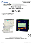
The amount of fluorescent material present
in the system is measured in a side-stream
of recirculating water passed through a
polished, quartz flow cell contained in the
optical detection system. An excitation light
source shines across the quartz tube and
causes the tracing material in the water to
fluoresce. A photodiode oriented 90
relative to the light source reads the amount
of light emitted. The quantity of light emitted
is directly proportional to the amount of
treatment chemical present in the system.
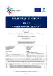
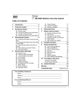
level (set point) and a control range are
selected. When the fluorescent material in
the sample stream falls below the lower
control range (the product set point minus
the control range), the chemical feed pump
is activated. Chemical is fed until the level
present in the sample stream reaches the
upper control range (the product set point
plus the control range). The chemical feed
pump is turned off until the sample stream
again falls below the lower control range.
Dosage
TRASAR Control
Activated
High Product
Alarm Level
Pump OFF
Upper Control Range
Product Set Point
Lower Control Range
Pump ON
Low Product
Alarm Level
Product Level
Time
One or more chemical metering pumps are
needed to feed chemical. Chemical pumps
are not supplied with the Opti-Pro.
90.0°
Excitation
By A Light
Source
Emission
Read By
Photodiode
Water
Sample Flow
The Opti-Pro is a microprocessor-based
fluorometer consisting of optics, an on/off
controller with electrical inputs/outputs for a
flow switch, 4-20mA signal, and data
logging. It is engineered to ensure reliability
and pre-assembled to simplify installation,
plumbing and calibration. The unit is
designed to provide trouble-free operation
with only simple, routine maintenance.
THEORY OF OPERATION
As the recirculating water sample flows
through the unit, the unit sends a signal to a
solid-state relay, which can control a
chemical feed pump. A desired product
998-0980
Rev. B
5
Operation Manual
Opti-Pro
SPECIFICATIONS
not feasible, contact Turner Designs for
assistance.
Turner Designs P/N: 6000-070
Power: 90-250 VAC, 50/60 Hz, 5 amps
Pump Relay: 90-250VAC, 50/60Hz, 5
amps (fused at 3.15 amps, Type “F”)
Signal Output: One 4-20 mA (isolated)
Dimensions: 8" W x 4" D x 11" H
Weight: 5 lbs. [2.3 kg]
Enclosure: Approximates NEMA 4X
Maximum Water Pressure: 100 psi
Inlet Pipe Size: ¼” NPT (male)
Outlet Pipe Size: ¼” NPT (female)
Ambient Temperature: 40-120F [4-49C]
Maximum Sample Temperature: 140F
[60C]
Relative Humidity: 0-100%
Overvoltage Category II
Pollution Category I
INSTALLATION
Pre-Installation/Installation
A pre-installation/installation checklist found
in Appendix A provides important guidelines
and information to aid in preparing for
installation.
Power & Utility Requirements
Power: 90-250 VAC, 50/60 Hz, 5 amps
Pump Control: Control pump rated at up
to 5 amps, 90-250 VAC (fused at 3.15
amps, Type “F”)
Signal Output: One 4-20 mA signal
(isolated)
Recirculating Water Sample: Supplied to
unit at 0.5 gpm minimum and less than
100 psi. (NOTE: Higher flow rates may
require more frequent cleaning of the
basket strainer.)
Drain: Sample outlet from the Opti-Pro
should be piped to drain with no back
pressure, i.e., drain pipes must be below
the unit. Do not combine the discharge
from other Opti-Pros to the Opti-Pro
discharge. In installations where this is
998-0980
Rev. B
Required Tools & Accessories
Standard plumbing and electrical tools
are required for installation.
A terminal strip screwdriver is provided
for making terminal strip connections.
The Opti-Pro should be piped as shown
in Figures 1 & 2 on pages 41 & 42.
Components may be purchased
separately or as a package through
Turner Designs.
Location & Sampling Point
The sampling point should be located
downstream from the recirculating pumps
where adequate mixing of the product has
occurred. Localized, high concentrations of
treatment may occur if the sampling point is
located directly downstream of the chemical
feed point. Conversely, localized, low
concentrations of treatment may occur if the
sampling point for the fluorometer is located
near the makeup water inlet.
It is extremely important to eliminate air
entrapment in the sample line. The best
way to accomplish this is to sample from the
center of the pipe or from the side of the
pipe.
The unit should not be installed in direct
sunlight; this could cause the internal
temperature of the unit to be significantly
higher than ambient and produce errors or
damage the components (Note the
maximum environment temperature is
specified at 120oF/49oC).
Do not install within 10 feet [3 m] of devices
such as large generators or transformers,
which generate a strong electromagnetic
field; cooling water recirculating pumps are
not a problem.
Do not mount this instrument on vibrating
walls or surfaces. Damage to critical
components can occur.
6
Operation Manual
Opti-Pro
Mechanical Connections
Refer to Figures 3 & 5 on pages 43 & 45
respectively for the location of the required
mechanical connections.
Two ¼ inch NPT pipe connections are
provided for ¼ inch PVC pipe hook-up. The
sample outlet line is ¼ inch female; the
sample inlet line is ¼ inch male shut off
valve.
If the Plumbing Accessory Kit (TD Part No.
6000-955) is purchased, the outlet line is ¼
inch NPT (female) to connect to usersupplied ¼ inch male piping; the inlet line is
½ inch NPT (female) to connect to usersupplied ½ inch male piping.
IMPORTANT: Sample discharge should
flow to an unrestricted drain. Pipe rises
greater than 10 feet [3 m] should be
avoided. In installations where this is not
feasible, contact Turner Designs for further
assistance.
Mounting eyelets are an integral part of the
plastic housing. Mounting the unit at eye
level is recommended.
INSTRUMENT AT BREAKER. Loosen the
proper terminal screw (screwdriver
provided) and insert wire from below into
terminal. Tighten screw firmly. A
termination legend is provided on the
backside of the enclosure door for
reference.
To disconnect a wire, TURN OFF MAIN
POWER TO THE INSTRUMENT AT
BREAKER. Loosen the termination screw
and pull the wire out of the terminal.
When finished, carefully insert the ribbon
cable onto the PCB and replace enclosure
face with the 6 screws.
Signal wires and power wiring should NOT
be run in the same conduit. Failure to
separate or shield these wires will result in
electrical interference.
IMPROPER INSTALLATION, USE,
APPLICATION OR UNAUTHORIZED
SERVICING OF THIS EQUIPMENT VOIDS
ALL WARRANTEES.
Electrical Connections
Only trained personnel should make
electrical connections.
Refer to Figure 4 on page 46 for the
"Terminal Connections", showing the
terminal strip location and configuration of
the required electrical connections for the
power, pump, flow switch and 4-20 mA
connections.
To access the terminal strip, TURN OFF
MAIN POWER TO THE INSTRUMENT AT
BREAKER, then remove the enclosure face
(6 screws). Remove the enclosure face
carefully as the keypad ribbon cable must
be removed from the printed circuit board
(PCB) to completely remove the enclosure
face. The ribbon cable is indexed on the
PCB to insure proper alignment upon
reassembly. (See Figure 4 on page 46).
There are two terminal strips within the
instrument. #1-6 are for AC connections
and #A-K are for input/output connections.
To connect a wire to the terminal strip,
TURN OFF MAIN POWER TO THE
998-0980
Rev. B
7
Operation Manual
Opti-Pro
START-UP
Before start-up, the following items should
be obtained:
If the screen is blank or dark, try adjusting
the screen contrast using the UP [] and
DOWN [] AROWS.
STEP #3:
Calibration Solution
Distilled Water
Dilute Acid
Calibration Accessory Kit
Plumbing Kit
During start-up, nine system values must be
entered. Record all set-up values in the
configuration record located in Appendix B.
These items are not included with the OptiPro. They are assigned individual part
numbers and can be ordered separately.
The Product Set Point in ppm is in the
chemical’s Product Knowledge Sheet in the
Dosage & Feeding section. The Product Set
Point is based on the system’s operating
parameters.
Background fluorescence (TRA Test Value)
can be found via a lab analysis report. In
most cases the Calibration Solution Value
will equal 1.0.
Press <ENT>. Before entering/changing
the first System Value, the unit will prompt
for the User I.D. The screen will read:
Please input ID:
Enter a valid USER ID (default is 8520) and
the screen will display:
Current: XXXX
New:
From the HOME screen, press <0> to
enter/change the first System Value;
Calibration Solution Value.
<0> CAL SOL’N. VALUE
This value relates the value of the tracer
standard to a fluorescence
measurement. The value is printed on
the label of the calibration solution and
listed in Table 1.
STEP #2:
Switch Main Power Switch under enclosure
face to the ON position (see Figures 3 & 4
on pages 43 & 44).
Press <0>
Press <ENT>
Key in appropriate Calibration Solution
Value
Press <ENT>
Press <HOME>
Start-Up Procedure
A diagram of the screens is located in
Appendix E
STEP #1:
Bring sample flow to unit -- check for leaks
in plumbing.
When power is first turned on, an ID screen
will appear for a few seconds, showing the
software version and date. After 10
seconds (or press <ENT> or <HOME> for
immediate access), the HOME screen will
appear. The HOME screen will display the
product dosage in PPM (3 digits) and the
pump status (ON/OFF).
XXX
PPM
Pump: ON
Sample Home Screen
998-0980
Rev. B
8
Operation Manual
Opti-Pro
Table 1. Traced Chemical Calibration
Solution Values
Calibration Solution
Value
Part Number
<4> CONTROL RANGE
1.00
Consultation
required*
This value determines the upper & lower
control settings (pump on/off) around the
Product Set Point. The Opti-Pro uses the
Control Range to turn the pump on & off.
Typically, the setting is 1-3 ppm.
* different chemicals such as fluorescein or
PTSA may be used. Expert assistance is
required to make this determination.
<1> PRODUCT FACTOR
The Product Factor = 1
This value relates the tracer measurement
to the actual level of Traced Chemical in the
sample. It is very important that the Product
Factor is entered correctly.
Press <1>
Press <ENT>
Key in Product Factor 1.0
Press <ENT>
Press <HOME>
This value is the background fluorescence
[%] for the recirculating water system as
measured by a laboratory. It varies from
site to site and can be found on the Lab
Report (Note: Use unfiltered value.). If you
do not know this value, use the value of
zero.
Press <2>
Press <ENT>
Enter TRA Test Value [%] ex. 4.0
Press <ENT>
Press <HOME>
<3> PRODUCT SET POINT
Obtain the desired dosage [ppm] of Traced
Chemical to be maintained in the
recirculating system from the chemical’s
Product Knowledge Sheet.
Press <3>
Press <ENT>
Key in Product Set Point [ppm]
Press <ENT>
Press <HOME>
998-0980
Press <4>
Press <ENT>
Key in Control Range [ppm]
Press <ENT>
Press <HOME>
The unit will reject as INVALID INPUT a
new control range value if the Product Set
Point minus the new value is not higher than
the Low Product Alarm level. It will also
reject a new control range value if the
Product Set Point plus the new value is not
lower than the High Product Alarm value.
<5> HIGH PRODUCT ALARM LEVEL
<2> TRA TEST VALUE
If the product level rises above this level
(and remains there for a 10-minute delay
period) a High Product Alarm will be
triggered. Upon alarm, the unit will default
to the High Product Alarm % to control
product feed; the High Product Alarm % will
be set later in this procedure. (see Alarm
Section).
Press <5>
Press <ENT>
Key in High Product Alarm Level [ppm]
Press <ENT>
Press <HOME>
The unit will reject (INVALID INPUT) a new
High Product Alarm level value if it is not
higher than the Product Set Point plus the
Control Range.
<6> LOW PRODUCT ALARM LEVEL
If the product level falls below this value
(and remains there for a 10-minute delay
period) a Low Product Alarm will be
triggered.
Rev. B
9
Operation Manual
Opti-Pro
Upon alarm, the unit will default to Low
Product Alarm % to control product feed;
the Low Product Alarm % will be set later in
this procedure (see Alarm Section).
Press <6>
Press <ENT>
Key in Low Product Alarm Level [ppm]
Press <ENT>
Press <HOME>
The unit will reject as INVALID INPUT a
new Low Product Alarm level value if it is
not lower than the Product Set Point minus
the Control Range.
<7> 4 mA OUTPUT
The 4-20 mA output can be connected by a
signal wire to a data logger or other device
to collect and remotely store data from the
unit. Outputs can be set to correspond to a
certain range of product reading. Typically,
the 4 mA output is set at 0 ppm.
Press <7>
Press <ENT>
Key in 4 mA Output
Press <ENT>
Press <HOME>
2. During an alarm condition, the 4-20 mA
output will still send out the dosage
level.
3. During calibration the 4-20 mA output
will send out a 4 mA signal.
<9> MASTER ID
For security, a USER ID is required to
change the System Values or calibrate the
unit. The original, or default, value is 8520.
The MASTER ID is required to view or
change the USER ID. To change the USER
ID, contact Turner Designs Technical
Support at 877-316-8049 for assistance
with the Master ID.
Press <9>
Key in Master ID
Press <ENT>
Key in new User ID.
Press <ENT>
Press <HOME>
STEP #4:
During start-up, the date, time, and alarm
output values must be entered. Record all
set-up values in the configuration record
located in Appendix B. Be sure to
download data from the data logger before
changing the date or time!
The unit will reject the entry if the 4 mA
value is > the 20 mA output value.
<8> 20 mA OUTPUT
The 4-20 mA output can be connected by a
signal wire to a data logger or other device
to collect and remotely store data from the
unit. Outputs can be set to correspond to a
certain range of product reading. Typically
the 20 mA output is set at twice the Product
Set Point [ppm].
1. The narrower the range of the 4-20 mA
settings, the greater the resolution.
Press <8>
Press <ENT>
Key in 20 mA Output
Press <ENT>
Press <HOME>
The unit will reject the new 20 mA value if it
is < than the 4 mA output value.
The date, time, and alarm output values are
accessed from the <> (clock) menu.
From the HOME screen, press <> to
access the date, time, and alarm values.
<0>
Hour
For the data logger to reference the correct
time, the hour of day must be entered. Only
numerical values 1-12 will be accepted.
Press <>, from HOME
Press <0>
Key in the hour of day (1-12)
Press <ENT>
Press <ESC> to return to clock menu
Notes:
998-0980
Rev. B
10
Operation Manual
Opti-Pro
<1> AM/PM
For the data logger to reference the correct
time (morning or evening), AM/PM must be
entered.
<6> Start-Up Timer
Press <>, from HOME
Press <1>
Press <ENT> to toggle between AM/PM
Press <ESC> to return to clock menu
<2> Minutes
For the data logger to reference the correct
time, the number of minutes after the hour
must be entered.
Press <>, from HOME
Press <2>
Key in minutes [0-59]
Press <ENT>
Press <ESC> to return to clock menu
When the unit is first activated, the Start-Up
Timer Alarm will monitor the amount of time
it takes the product dosage to fall within the
set point, ± Control Range -- and remain
there for at least 10 minutes. If the time
exceeds the pre-defined value, then it will
trigger The Start-Up Timer Alarm.
Press <>, from HOME
Press <6>
Press <ENT> to toggle
Press <ESC> to return to clock menu
If the time exceeds this pre-defined value
(1-168 hours), the Start-Up Timer Alarm will
be triggered -- indicating a chemical feed
problem. A setting of OFF disables the
alarm.
<7> Limit Timer
<3> Month
For the data logger to reference the correct
date, the month of the year must be
entered.
Press <ESC> to return to clock menu
Press <>, from HOME
Press <3>
Key in the month (1-12)
Press <ENT>
Press <ESC> to return to clock menu
This alarm monitors the amount of time the
inhibitor pump is on. If the time exceeds
this period (from 1-1440 minutes), the alarm
will be triggered, indicating a possible
inhibitor pump or chemical feed problem. A
setting of OFF disables this alarm.
<4> Date
For the data logger to reference the correct
date, the day of the month must be entered.
The Limit Timer Alarm will not begin to
monitor until the Start-Up Timer is finished.
<8>
Press <>, from HOME
Press <4>
Key in the day (1-31)
Press <ENT>
Press <ESC> to return to clock menu
<5> Year
For the data logger to reference the correct
date, the year must be entered.
Press <>, from HOME
Press <5>
Key in year [00-99]
Press <ENT>
998-0980
Rev. B
Press <>, from HOME
Press <7>
Press <ENT> to toggle
Press <ESC> to return to clock menu
Low Product Alarm %
The unit can be set to feed a pre-defined
level of product during various alarm
conditions. The user can define whether to
feed 0-100% product during a low product
alarm, a no flow alarm, a fluorometer alarm,
a limit timer alarm, a start up timer alarm or
a high temperature alarm.
Press <>, from HOME
Press <8>
Press <ENT> to toggle (0-100%)
Press <ESC> to return to clock menu
11
Operation Manual
Opti-Pro
If both a High or Low Product Alarm and a
System Alarm occur at the same time, the
feed setting chosen for Low Product Alarm
will take precedence.
<9> High Product Alarm %
The unit can be set to feed a pre-defined
level of product during a high product alarm.
The user can define whether to feed 0100%.
Press <>, from HOME
Press <9>
Press <ENT> to toggle (0-100%)
Press <ESC> to return to clock menu
If both a High or Low Product Alarm and a
System Alarm occur at the same time, the
feed setting chosen for Low Product Alarm
will take precedence.
The Opti-Pro unit start-up has now been
completed. After start-up, wait a minimum
of 15 minutes before calibrating to allow the
unit to come to equilibrium.
Monitoring Mode
To assist in understanding the improvement
in control the Opti-Pro achieves; the unit
should initially be used to monitor and
document the current level of control
capability. To do so, do not connect (or
disconnect) any control devices from the
unit.
Reset the following System Values:
Value
Access
Key
Setting
Low Product Alarm
<6>
0
High Product Alarm
<5>
999
998-0980
Rev. B
12
Operation Manual
Opti-Pro
CALIBRATION
STEP #6
Calibration Procedure
Press <1>:
All calibration steps must be completed for
changes to be registered!
Refer to Figures 3 & 5 on pages 43 & 45
respectively, for locations of items. A
diagram of display screens is located in
Appendix E.
STEP #1
Close flow cell shut-off valve. The valve is
closed when oriented horizontally.
STEP #2
Clean unit by injecting acid with a syringe
into the flow cell. The syringe screws onto
the Luer Lock fitting on the inlet of the flow
cell (see Figure 3 on page 43). Fill syringe
with 60 ml of dilute acid (10% Sulfuric Acid
recommended -- 1:1 HCl is acceptable if the
cell is well rinsed). Screw syringe onto
fitting. Inject dilute acid at a slow, steady
rate into flow cell and allow to stand for 3-5
minutes. Using a clean 60 ml syringe, flush
flow cell thoroughly with 60 ml of blank
solution.
A syringe is provided in the Opti-Pro
Calibration Accessory Kit (Turner Designs
Part No 4000-930).
STEP #3
Press <ENT> from the HOME screen:
1.
Calib 2. Cal data
xx Day(s) Ago
Cal
BLANK
SOLUTION
Using the syringe for the blank solution,
flush flow cell with 60 ml of blank solution
via the Luer-lock Injection Port. Then inject
another 60 ml blank solution and allow it to
remain in the flow cell by leaving the syringe
attached.
Bubbles trapped during injection are a
possible source of instrument error. With
the syringe in a vertical position, tap against
a solid object to move bubbles to the needle
end of the syringe. Then, force bubbles out
by pushing a small amount of solution
through the needle end of the syringe.
STEP #7
Press <ENT>:
BLANK %:
XX
Any value < 25% is acceptable. If blank is >
25% and <0> is pressed, an error message
will be received. Press <ESC> to abort
calibration and check the blank solution.
When reading is stable, press <0>. The unit
will display a flashing "WAIT/wait” message
in the lower right-hand corner of the screen
while the unit registers the blank.
Then, the screen will display:
To continue
Press <ENT>
STEP #4
Press <1> the unit will request ID entry
(unless recently entered).
Please input ID:
Enter valid USER ID (originally 8520) on the
keypad if requested.
STEP #5
Press <ENT>:
CALIBRATE SYSTEM
<1> To Start
998-0980
Rev. B
13
Operation Manual
Opti-Pro
STEP #8
Notes on Calibrating
Press <ENT>:
1. Calibrate the Opt-Pro unit when you
have time to go through all steps without
interruption ( 10 minutes). If the
keypad is not used for 15 minutes, the
unit will automatically return to the
HOME screen. The previous calibration
will be maintained.
CALIBRATION SOLUTION
Using a clean syringe, flush flow cell with 60
ml of calibration solution via the Luer-lock
Injection Port. Then inject another 60 ml
calibration solution and allow it to remain in
the flow cell by leaving the syringe attached.
STEP #9
3. A request to begin calibration when an
alarm is activated will be denied, unless
the alarm is for:
Press <ENT>:
CAL SOLUTION %:
XX
Wait for reading to stabilize. The CAL
SOLUTION % should be 1-10%
When the CAL SOLUTION % is stable and
between 1-10, press <*>. The unit will
display a "WAIT/wait" message in the lower
right-hand corner of the screen while it
registers the calibration solution.
Then, the screen will display:
High Product Alarm ("P-H")
Low Product Alarm ("P-L")
4. The following alarms will not be
monitored during calibration:
High Product Alarm ("P-H")
Low Product Alarm ("P-L")
No Sample Flow Alarm ("N-F")
5. If an internal unit function alarm ("F-A"
alarm) occurs during calibration, when
you return to the HOME screen, "ALM"
will be blinking in the upper left-hand
corner of the screen. Correct the
condition causing the alarm, and then
recalibrate the unit.
To continue
Press <ENT>
STEP #10
Remove the syringe and press <ENT>:
6. During calibration, the 4-20 mA output
will send out a 4-mA signal.
Press <1> to End
Calibration
Press <1> to accept the calibration settings.
The calibration is now complete.
YOU MUST PRESS <1> OR THE
CALIBRATION WILL REVERT TO THE
PREVIOUS SETTINGS!
STEP #11
Open flow cell shut-off valve. The valve is
open when the handle is oriented
vertically.
STEP #12
Press <HOME> to return to the HOME
Screen and normal operations.
998-0980
2. Pump output will be OFF (no chemical
feed) during calibration.
Rev. B
7. Use distilled or deionized water as blank
solution. If you are not using
commercial distilled water, check your
source of blank solution against distilled
water for background fluorescence. DO
NOT USE MAKE-UP WATER AS A SOURCE
OF BLANK SOLUTION. Use of the wrong
blanking solution can result in
inaccurate or low product dosage.
8. Use only approved Traced Chemical
Calibration Solutions. These solutions
meet strict specifications that cannot be
achieved if made at the customer's site.
Use of solutions that have not been
approved may result in inaccurate
product dosages.
14
Operation Manual
Opti-Pro
9. All solutions are injected with a syringe
into the stainless steel Luer-lock
Injection Port. Depress plunger at a
steady, slow rate.
10. Use separate syringes for blank and
calibration solutions.
11. Avoid injecting bubbles into the unit.
Bubbles trapped when injecting the
blank and calibration solution are a
possible cause of instrument error. With
the syringe in a vertical position, tap the
syringe against a solid object to move
the bubbles to the needle end of the
syringe. Then, force the bubbles out by
pushing a small amount of solution
through the needle end of the syringe.
12. The LEFT ARROW [] may be used to
return to previous calibration screens.
13. During calibration sequence, MAKE
SURE to wait for BLANK % and CAL
SOLUTION % readings to stabilize
before pressing the appropriate key on
the keypad.
14. Do not allow calibration solution to sit in
flow cell longer than necessary
(approximately 2 minutes). To abort the
calibration and maintain current
calibration settings, press <ESC> before
step 9 is completed. The unit will
prompt:
Table 2. Calibration Data
Blank
Cal Std
Access Key
<ENT> & <2>
Default
0.0
500.0
Range
0-250
0-1,000
[A] Blank: Shows raw data output for blank
solution as set during calibration. It can be
used to check proper calibration. It is
derived by multiplying the Blank % reading
in Step 7 of the calibration procedure by 10.
Thus, if Blank % reads 10% with blank in
the flow cell, then this reading should be
between 100-109.
Blanking capability of the instrument is
25% (e.g. maximum blanking of raw data is
250.0)
[B] Cal Std: Shows raw data output for the
standard solution as set during calibration.
It can be used to check proper calibration.
It is derived by multiplying the CAL
SOLUTION % reading in Step 9 of the
calibration procedure by 10. Thus, it should
read between 20-100 when the unit has
been properly calibrated. For example, if
CAL SOLUTION % reads 5% with the
calibration solution in the flow cell, then this
reading should be 50.
15. To abort the calibration and maintain
current calibration settings, press<ESC>
before step 9 is completed. The unit will
prompt:
<1> Abort Cal
<ESC> Continue
Press <1> to abort.
16. The entire calibration procedure must be
completed to store the new values
entered during calibration.
Calibration Data Screen
This screen provides a check on proper
calibration. It is accessed from the HOME
screen by pressing <ENT>, then <2>.
998-0980
Rev. B
15
Operation Manual
Opti-Pro
INTERNAL DATA LOGGER
The Opti-Pro is equipped with an internal
data logger to record the unit's output. Data
is saved in a binary (BIN) format to be
downloaded and converted to ASCII data
with the Internal Data Logger (IDL)
software.
Data Logger Parameters
measurement), from the data logger
menu, press <1>:
Interval: 1 min
<ENT> to toggle
Press <ENT> to toggle from 1, 2, 3, 5,
10, 20, or 30 minutes, or 1 second
The unit's data logger is accessed from the
HOME screen by pressing the data disk
<> symbol on the keypad. From the data
logger menu, you can turn the data logger
on/off, set the interval, download, and erase
data.
4. To download data to a Windows based
PC or to erase data, from the data
logger menu, press <2> or <3>,
respectively.
The clock is important to the data logging
functions. Once the date and time are set
and data has been logged, download the
current data before changing the date or
time or existing data may be corrupted.
The IDL software is designed to interface
from the Opti-Pro to a Windows 95 through
XP-based PC. The IDL program is used to
download data from the Opti-Pro and
convert it to an ASCII format for use with a
spreadsheet or other program. To install
the IDL software:
1. From the HOME screen, press <> to
see the data logger menu. Before
entering/changing the data logger, the
unit will prompt for the Master ID. At this
point, contact Turner Designs Technical
Support and they will assist you with the
Master ID:
Please input ID:
Installing Internal Data Logger (IDL)
Software
Insert the CD into your computer.
Using Windows explorer go to the
drive containing CD and open the
folder titled Opti-Pro Software v. 2.0.
Double click on the setup.exe file to
begin installation.
The Master ID is different than the User
ID. After entering the Master ID the
screen will read:
Datalogger:
<0> - <3>
2. To log data or stop logging data, press
<0>:
Status: Stop
<ENT> to toggle
Press <ENT> to toggle from Stop to
Logging.
3. Important: Download current data before
changing the date or time to avoid data
corruption.
To set the data logging interval (how
often the unit records a sample
998-0980
Rev. B
16
Operation Manual
Opti-Pro
Running the Internal Data Logger
Software
To download data from the Opti-Pro:
1. Using the cable provided (a male and
female DB9 connector at each end),
connect computer to the unit's serial port
(RJ-11 female). Refer to Figure 4 on
page 44 to locate.
2. Start IDL program on PC by clicking
twice on the IDL.exe icon. The IDL
Main Menu will appear.
3. Click on Serial Port Setup to select the
appropriate PC COM port (1,2, or 3).
4. Click on Download Data from Instrument
to File to display the downloading box
on the PC.
Data may be downloaded and converted
to an ASCII file in a single process by
clicking on Download and Convert Data
from Instrument to File. In this case,
IDL will prompt you for downloading,
and then conversion, in a single process
incorporating steps 5-10.
5. From the Opti-Pro, set the data logger to
Stop, by pressing <> from the HOME
screen, then <0>, then <ENT> to toggle.
6. From the Opti-Pro, access the
downloading screen by pressing <2>
from the data logger main menu:
Download data:
5x <8> to start
7. On the keypad, press <8> five times to
start downloading data. The PC will
display a bar graph and data block
countdown. The Opti-Pro will display:
Download data:
Data Blks: XX
If there is an error in downloading data,
the following screen will be displayed:
Make sure the correct serial port has
been selected (IDL software main
menu).
Check to make sure the Opti-Pro date
and time functions have not been
changed for the current data logged.
Verify steps 1-7 have been completed.
Correct screens must be displayed on
both the computer and Opti-Pro.
8. When downloading is finished, IDL will
prompt to name the file and select the
path (folder) for the downloaded file.
Click on Browse to change the name or
path; or accept the default name
(test.bin) and path. Then, click on OK to
return to the Main Menu.
If you would like to wait until later to
convert the data to ASCII format in order
to save disk space, then skip to step 12.
To convert data to an ASCII file now, go
on to step 9.
9. To convert a BIN file to a regular ASCII
file (PRN file), from the PC click on the
Convert Downloaded Data File to ASCII
File. IDL will then prompt what file you
would like to convert to ASCII. Click on
Browse to locate the file or click on OK
to accept the default file.
10. Click on OK to begin conversion. IDL
will display "Conversion has started."
IDL will convert the BIN file to an ASCII
file of the same name with the extension
"PRN". When "Conversion completed"
appears, click on OK to return to IDL
Main Menu.
11. To exit IDL, click on the “X” in the upper
right-hand corner or select “exit” from
the file menu.
12. Disconnect computer from the unit.
Erase data currently in the Opti-Pro by
pressing <> from the HOME screen,
then <3> from the data logger menu:
Erase data:
5 x <9> to start
Comm Error !!
<ESC> to retry
If the error screen appears, press
<ESC> and make sure the serial cable
is securely connected and operational.
998-0980
Rev. B
17
Operation Manual
Opti-Pro
When data is erased, the unit will display
and should be replaced promptly. The
unit can remain in operation during this
replacement. Readings should be
monitored during this replacement time
as small variances might occur. Refer
to the Replacement Parts Section for
replacement plugs.
Erase data:
All Data Erased
13. Enter new internal data logging
parameters on the Opti-Pro, if desired,
or resume logging with previous
parameters.
14. Return unit to normal operation.
The following preventative maintenance
should be performed to ensure optimum
Opti-Pro operation and maximum life.
Examining Downloaded Data
Cleaning the Basket Strainer
The ASCII-format "PRN" files can be
opened, viewed, or printed using most
standard computer programs. To examine
the data, run your program, then open or
import the "PRN" file containing the
downloaded data. A typical line of data
from the internal data logger will look like
this (your numbers will vary):
The basket strainer screen should be
cleaned as needed:
00001:
10/24/91
14:10:28
=
11.300
Index
Date
Time
Sample
Reading
PREVENTATIVE MAINTENANCE
Proper preventative maintenance is critical
to the success of fluorescent traced
technology. Once the unit is installed,
started-up, and calibrated, the initial settings
should not require change. Any start-up or
shutdown must be made using the Opti-Pro
Main Power Switch (see Figures 3 & 4 on
pages 43 & 44).
System Values are retained in battery
back-up memories for up to five years.
However, the Start-Up procedure should
be followed to ensure fluorometer
calibration and control settings are
correct if the unit has been disconnected
for any length of time.
This unit has been assembled with a
new desiccant plug to ensure the area
surrounding the flow cell is free of any
moisture. As this plug absorbs
condensate, it will change from a light
blue to light pink at the saturation point
998-0980
Rev. B
1.
2.
3.
4.
5.
Shut off inlet valve to basket strainer.
Remove screen and clean.
Replace screen.
Open inlet valve to basket strainer.
Wait for unit to equilibrate and air to
purge from the unit.
Calibrating
Calibration should be checked and
performed regularly. Typically, calibration is
necessary every two weeks to once a
month. The calibration solutions must be
carefully selected. Consultation will be
necessary:
Traced
Chemical
Compound
Cal Sol’n.
Value
Part
Number
**
1.00
**
**Values to be provided by chemical supplier
Cleaning the Flow Cell
Flow cell cleaning frequency is dependent
on the quality of the water sample being
monitored. The flow cell is unlikely to clog,
but occasionally (though rarely) residue can
build up on the inside of the quartz cuvette,
especially where oily water is involved. A
fouled or discolored flow cell can result in
low or erratic readings. For routine
cleaning, follow steps 1 & 2 in the
Calibration Procedure. Be sure to open the
18
Operation Manual
Opti-Pro
flow cell shut-off valve when cleaning is
completed.
Replacement Parts
For cleaning the flow cell with a brush,
perform the following steps. Refer to Figure
3 on page 43.
1. TURN OFF MAIN POWER SWITCH
2. Shut off flow to flow cell. Flow is off
when valve handle is horizontal. It is
recommended that the inlet valve be
closed and the 3-way outlet valve also
be closed (the outlet valve is then open
to atmosphere -- see Figures 1 & 2,
pages 41 & 42.
Common Replacement Parts:
3. Remove clean-out plug. See Figure 3,
page 43.
4. CAUTION: After injecting acid solution
into the flow cell, be sure to flush it out
completely BEFORE removing the
clean-out plug.
5. Dip flow cell brush into dilute acid
solution and insert gently into clean-out
opening.
6000-970
Desiccant Plugs (Pkg. 3)
6000-350
Flow Cell Brushes (Pkg 3)
6000-119
Data Cable
120-0110
Flow Switch
4000-930
Calibration Accessory Kit
IMPROPER INSTALLATION, USE,
APPLICATION OR UNAUTHORIZED
SERVICING OF THIS EQUIPMENT VOIDS
ALL WARRANTEES.
6. Slide brush gently up and down in the
opening to remove any coating on the
quartz cuvette.
7. Replace flow cell clean-out plug.
8. Turn on flow. Flow is ON when valve
handle is oriented vertically.
9. Turn ON Main Power Switch.
10. Calibrate unit after allowing it to warm
up for 15 minutes (see Calibration
Procedure).
998-0980
Rev. B
19
Operation Manual
Opti-Pro
ALARMS
Alarms have been built into the Opti-Pro to
warn about conditions relating to product
levels and internal instrument functions.
Two general types of alarms exist:
1. System Function Alarms: Fluorometer
(lamp) and No Flow ("F-A” & "N-F"
alarms). Refer to Table 3.
2. Product Function Alarms: Refer to
Table 4.
Refer to Appendix F (Table 5) for alarm
default values.
N-F
F-A
Certain alarms will trigger other alarms
because a failure in one part of the unit
causes what appears to be a failure in
another part of the unit. For example: If the
lamp light source is bad (F-A), this condition
may also trigger the Product Too Low Alarm
(P-L) even if there is really nothing wrong
with the product level.
Alarm History
Alarm Delay
To avoid unnecessary triggering of alarms,
the condition must be in effect for a certain
delay period (see Tables 3 & 4).
Alarm Activation
When an alarm is triggered, "ALM" will blink
in the upper left-hand corner of the HOME
screen. From any other screen, when the
alarm is first activated, the unit will return to
the HOME screen, where it will display the
“ALM” message in the upper left-hand
corner. Pressing the <ESC> key will display
the current alarm. Take the appropriate
action to clear the condition (see
Troubleshooting Section).
The alarm history can be viewed, by
pressing <> (Left Arrow) from the HOME
screen. This shows which alarms have
been activated since the alarm history
screen was last cleared. To clear this
screen, press <*> five times while the alarm
history screen is displayed; "No Alarm Since
Last Reset" will be displayed.
Notes About Alarms
1.
No alarms are monitored when the
unit is turned OFF.
2.
Certain alarms are not monitored
during calibration (see Notes on
Calibrating in Calibration Section).
3.
When the unit is first powered up,
the Low Product Alarm will begin to
be monitored 10 minutes after the
dosage rises above the Lower
Control Range (set point minus the
control range). However, if the
dosage falls below the Lower
Control Range within the 10-minute
delay period, then the 10-minute
delay period will be restarted. Thus,
a problem or spike during start-up
will not mis-trigger the Low Product
Alarm.
4.
When the unit is first powered up,
the High Product Alarm will begin to
be monitored 10 minutes after the
dosage falls below the Upper
Control Range (set point plus the
control range). However, if the
dosage rises above the Upper
Control Range within the 10-minute
When the condition triggering the alarm is
cured, "ALM" will disappear from the HOME
screen.
Alarms cannot be aborted without curing the
problem.
NOTE: When an alarm is triggered,
chemical feed will default to the High
Product % and Low Product % settings.
Multiple Alarms
If multiple alarms are triggered, alarms will
be listed on the alarm screen when <ESC>
is pressed from the HOME screen. Alarms
are not listed in the order they occur. For
example, the alarm screen might display:
998-0980
P-L
Rev. B
20
Operation Manual
Opti-Pro
delay period, the 10-minute delay
period will be restarted. Thus, a
problem or spike during start-up will
not mis-trigger The High Product
Alarm.
5.
All alarms will reset automatically if
the alarm condition is corrected
except the START-UP TIMER and
LIMIT TIMER, which are latched-in
and require manual reset (refer to
the Alarm Help Screen). Alarms
cannot be stopped without fixing the
problem.
6.
When the unit is first activated, the
Start-Up Timer Alarm will monitor
the amount of time it takes the
product dosage to fall within the set
point, ± control range -- and remain
there for at least 10 minutes. If the
time exceeds the pre-defined value,
then it will trigger the Start-Up Timer
Alarm. The Start-Up Timer Alarm
defaults to the Low Product Alarm
Pump settings.
7.
The Limit Timer Alarm will not begin
to monitor until the start-up timer is
finished. The Limit Timer Alarm
defaults to the Low Product Alarm
pump output settings.
8.
During an alarm condition, the 4-20
mA will still send out the dosage
level.
9.
During an alarm condition, the
chemical will or will not feed as set
by the user using the High and Low
Product Alarm Settings.
Delay
(min.)
Alarm
Condition
Normal
Lamp
(F-A)
1
OFF
ON
No Sample
Flow (N-F)
10
OFF
ON
998-0980
[A] Lamp (F-A): Indicates the status of the
excitation light source. Reports whether the
lamp is OFF or ON. If the power is ON and
the lamp is good, the diagnostic screen will
display “Lamp: ON”.
[B] No Sample Flow (N-F): If there is a
problem with the sample flow lasting for the
10 minute delay period, a "N-F" alarm will
be displayed. The flow switch used is rated
at 0.5 gpm minimum flow (tolerance is 0.40.6 gpm).
If there is a "N-F" alarm, check terminal
connections to the flow switch. Check the
sample feed lines and the unit's flow cell for
any restriction.
NOTE: Only trained personnel should
perform electrical connections.
If a system function alarm is activated, the
screen will display "F-A" (lamp) or “N-F” (no
flow) when <ESC> is pressed from the
HOME screen.
F-A
N-F
Press <*> from the HOME screen to access
the diagnostic screens (refer to Appendix F,
Table 5, for default values).
If the Lamp displays "OFF" and there is
power to the unit, contact Turner Designs
at 877-316-8049 in the USA. International
Customers should call Turner Designs at
408-212-4046.
Table 4. Product Function Alarms
Table 3. System Function Alarms
Alarm
System Function Alarms Definitions
Rev. B
Delay
(min.)
Range
Default
High Product
(P-H)
10
0.2-999
999
(ppm)
Low Product
(P-L)
10
0-997
0 (ppm)
Start-Up Timer
(S-A)
10
1-168
hours
OFF
Limit Timer
(L-A)
10
1-1440
min.
OFF
Alarm
21
Operation Manual
Opti-Pro
Pressing <ESC> from the HOME screen
allows the user to determine which product
function alarm is activated.
The Limit Timer will not start to monitor until
the Start-Up Timer Alarm is finished. To
clear a Start-Up Timer Alarm, press <ESC>
<8> from the Home Screen.
Product Function Alarm Definitions
[P-H] Product Too High
If the product level rises above the user-set
level (see Appendix B), and remains there
for the 10-minute delay period, a "P-H"
alarm will be noted.
If there is a "P-H" alarm, check pump status
on the HOME screen against actual pump
action. Check terminal connections from
the unit to the pump and chemical feed
lines. Is the High Product Alarm Level set
too low? Verify that calibration has been
performed properly.
[P-L] Product Too Low
[L-A] Limit Timer
This alarm monitors the amount of time the
solenoid pump is on. If the time exceeds
this period (from 1-1440 minutes), the alarm
will be triggered, indicating a possible
solenoid pump or chemical feed problem. A
setting of OFF disables this alarm.
When triggered, the Limit Timer defaults to
the Low Product Alarm pump output
settings.
The Limit Timer Alarm will not begin to
monitor until the Start-Up Timer is finished.
To clear a Limit Timer Alarm press <ESC>
<7> from the Home Screen.
If the product level falls below the user-set
level (see Appendix B), and remains there
for the 10-minute delay period, a "P-L"
alarm will be noted.
If there is a "P-L" alarm, check pump status
on the HOME screen against actual pump
action. Check terminal connections from
the unit to the pump and chemical feed
lines. Is the Low Product Alarm Level set
too high? Verify that calibration has been
performed properly.
[S-A] Start-Up Timer
When the unit is first activated, the Start-Up
Timer Alarm will monitor the amount of time
it takes the product dosage to fall within the
set point, ± control range -- and remain
there for at least 10 minutes.
If the time exceeds the pre-defined value,
then it will trigger the Start-Up Timer Alarm.
If the time exceeds this pre-defined value
(1-168 hours), the Start-Up Timer Alarm will
be triggered indicating a chemical-feed
problem. A setting of OFF disables the
alarm. When triggered, The Start-Up Timer
defaults to the Low Product Alarm pump
output settings.
998-0980
Rev. B
22
Operation Manual
Opti-Pro
6. In the U.S., contact Turner Designs at
877-316-8049 (see Service
Assistance/Returned Goods Section).
TROUBLESHOOTING
Because the Opti-Pro includes hardware,
software, and chemistry, it is important to
collect all diagnostic data first. A
troubleshooting worksheet is provided in
Appendix G to facilitate data collection.
After collecting all data on the worksheet,
most problems can be solved over the
phone. Refer to the Service Assistance
Section for the appropriate telephone
numbers.
International customers should contact
Turner Designs at 408-212-4046.
Diagnostics
When using this guide, it is assumed that all
problems associated with an alarm have
been resolved first. Something as simple as
a clogged basket strainer can lead to other
alarm messages, which could all be solved
at one time simply by cleaning basket
strainer. Generally speaking, if there is no
System Function Alarm ("F-A” alarm), this is
persuasive evidence that the electronics of
the instrument are functioning properly. In
that case, it is likely that any problem is
either mechanical, or has resulted from
another system problem, or from the
operator's unfamiliarity with the unit.
The troubleshooting procedure works best
in this sequence:
1. HANDLE ANY ALARMS FIRST (see Alarms
Section)
2. Determine whether or not System
Values have been entered correctly (see
recorded values in Appendix B, and the
System Default Values in Appendix F,
Table 5).
3. Perform Diagnostics procedure as
described on the following page.
4. Determine whether or not the chemistry
is behaving as expected. Does the
blank read close to zero on the HOME
screen and calibration solution read
between 1-10% on the diagnostic
screen "CAL SOLUTION %"? Check
the "Cal data" screen (see Calibration
Data Screen) to determine whether the
last calibration seems correct.
5. Complete the Troubleshooting
Worksheet (Appendix G).
998-0980
Rev. B
The Opti-Pro contains diagnostic screens
and functions to aid in troubleshooting.
These functions are accessed from the
HOME screen by pressing <*>, then <ENT>
to page through the series of 4 screens.
Press the <LEFT ARROW> to return to a
previous screen, or <ESC> or <HOME> to
return to the HOME screen.
1. From the HOME screen, press <*>:
Turner Designs
Ver G5UL-1X XXXX
2. From the above screen, press <ENT>:
Raw: XXX
FS% XX
Raw: The "raw" signal output from the unit's
light detector. This is the output the OptiPro uses (in conjunction with the Product
Factor, Cal Solution Value, TRA Value, etc.)
to arrive at the [ppm] readout on the HOME
screen. It can be used to diagnose
problems with the unit. For example, if the
HOME screen always reads zero, and the
raw reading is also zero, there may be an
optics problem. If the HOME screen reads
zero but the Raw reading does not read
zero, then check the Cal Sol’n. Value or the
Product Factor Value to make sure the
proper value is entered.
FS%: Acts like an analog meter. Indicates
the raw signal output as a percentage of the
maximum that can be read.
Value
Range
Raw
0.00 to 1000.00 (reading >1000.00
will display "OVER")
FS%
0 to 208 (if Blank equals 0)
23
Operation Manual
Opti-Pro
3. From the above screen, press <ENT>
Service Assistance
Test:1:
PUMP
1: PUMP: A solid-state relay controls one
chemical pump through connections
(terminal strip connections 4-6). If the OptiPro is connected to a pump or other control
device via terminal strip connections 4-6,
this function allows you to test whether the
unit's internal circuitry is operating and
terminal strip connections are correct. To
test the pump/device control of the Opti-Pro,
the pump/device itself must be on, working,
and properly connected to the terminal strip.
Then, press <1> from this screen, then
<ENT> to toggle the pump/device ON and
OFF. The pump/device should go on when
ON is selected and off when OFF is
selected. If it does not, then be sure to
check the pump/device itself first, and then
check the terminal strip connections (trained
personnel ONLY). When the test is
finished, return to the HOME screen and
pump/device control will revert to control by
current unit values.
IMPROPER INSTALLATION, USE,
APPLICATION OR UNAUTHORIZED
SERVICING OF THIS EQUIPMENT VOIDS
ALL WARRANTEES.
This function can serve as a "manual
override" for pump control tests. While on
this screen, you can turn a pump/device on
and off regardless of the unit values
previously entered.
4. From the above screen, press <ENT>
Oper: XXXX Hrs
Lamp ON
Flow: ON
Oper: Indicates how many hours the unit
has been in operation since installation.
Lamp: Indicates whether the LED light
source is operating properly.
Flow: Indicates whether the flow is
ON/OFF.
5. From the above screen, press <ENT>
Blank: X.X
Cal std: XXX.X
For definitions, ranges, and default values
of these items, see Calibration Data Screen
Section.
998-0980
Rev. B
24
Operation Manual
Opti-Pro
Troubleshooting Guide
[HANDLE ANY ALARMS FIRST]
SYMPTOM
HOME screen displays
over/OVER (blinking from
over to OVER).
A blinking 'over/OVER' is a
different symptom than a
steady 'OVER' and indicates
that the sample reading
exceeds 999. This is most
likely related to the System
Values entered for the site.
If, for example, a Cal Sol’n
Value of 200 was erroneously
entered, the unit's numerical
calculation of the sample
reading might exceed 999.
(NOTE: Examine "Possible
Cause"/"Solution" in the
numbered order.)
HOME screen displays
OVER (not blinking from over
to OVER).
A steady 'OVER' is a different
symptom than a blinking
'over/OVER' and indicates
that the sample reading is too
high for the unit's light
detector. This is related to
the chemistry of the sample
and displays that the sample
readings are too high for the
unit at the current sensitivity
level. (NOTE: Examine the
"Possible Cause"/"Solution"
in the numbered order.)
HOME screen displays minus
sign (negative readings), i.e.,
sample is reading less
concentrated than blank
value as set during last
calibration.
998-0980
POSSIBLE CAUSE
SOLUTION
1. System Values are
incorrect (i.e. Product
Factor, Cal Sol’n Value,
etc.).
Check the Configuration Record
for the site. Access the System
Values and verify that they are
entered correctly.
2. Incorrect calibration
Check the Calibration Data
screen. Recalibrate the unit; be
sure to use the correct calibration
solution and that the reading is
between 1% - 10%. Check the
expiration date of the solution.
3. Chemical feed too
high.
Check feed pump. Confirm high
concentration using wet test.
4. The Opti-Pro is, or has
been, in alarm. Back-up
control has forced
chemical feed on.
Deactivate chemical feed by
setting the High & Low Product
% settings to 0%. Once the
system returns to a normal level,
reset the alarm responses to the
desired settings.
1. Possible optics
problem.
Check the FS% reading in the
Diagnostics sequence.
2. Incorrect calibration.
Recalibrate the unit, making sure
that you are using the correct
Calibration Solution, and that it
reads between 1 – 10%. Check
the expiration date of the
solution.
3. System Values are
incorrect (i.e. Product
Factor, Cal Sol’n Value,
etc.).
Check the Configuration Record.
Access the System Values and
verify they are entered correctly.
4. Chemical feed too
high.
Check feed pump. Confirm high
concentration using wet test
1. Fouled flow cell.
Thoroughly clean and rinse flow
cell with recommended solution,
using a flow cell cleaning brush if
necessary.
2. Calibrated with
contaminated blanking
solution, or the calibration
solution was used instead
Recalibrate
Rev. B
25
Operation Manual
Opti-Pro
SYMPTOM
POSSIBLE CAUSE
SOLUTION
of the blank solution.
998-0980
Rev. B
26
Operation Manual
Opti-Pro
Troubleshooting Guide Continued
SYMPTOM
POSSIBLE CAUSE
HOME screen reads zero.
System Values incorrectly
set
Make sure valid System Values
were entered (see Appendix F).
Screen blank or black.
LCD's screen contrast too
high or too low
If screen is blank, adjust contrast
by pressing UP ARROW (if screen
is black, use the DOWN ARROW)
continuously until screen is visible.
Use arrows to fine adjust.
Unit does not calibrate.
Failure to complete entire
calibration procedure
You must press <1> at the end of
the calibration sequence for the
unit to accept the values.
Recalibrate.
Pump is not operating
properly.
1. Problem with "Product
Feed During Alarm"
settings (if alarm active);
or terminal strip
connections; or pump
itself.
If there is an alarm, check the High
& Low Product Alarm %. Settings
on unit (System Values). Refer to
Diagnostics Section; pump test
function, to test if the unit is
properly controlling the pump.
Make sure pump itself is powered
and operational.
2. Fuse has “blown.”
Replace fuse with spare located on
the Main PCB.
TRA value ineffective (i.e.
HOME screen reading
does not change when the
TRA value is changed).
This is not usually cause
for alarm as the HOME
screen reading is a result
of a combination of
factors.
Do not attempt to change current
settings unless you are certain
something is wrong. Consult
Turner Designs at 877-316-8049.
For example, a low product factor
will cause the TRA value itself to
have a minimal effect.
Unit does not respond to
calibration solutions.
System Values incorrectly
entered
Insure correct Product Factor, TRA
Test Value, and Cal Sol’n Value
have been entered (see Appendix
F).
998-0980
Rev. B
SOLUTION
27
Operation Manual
Opti-Pro
RESPONSIBILITY FOR SAFE
DELIVERY
Turner Designs has done everything
possible to protect this equipment from
damage due to normal transportation
hazards. After the product leaves the
manufacturing site, responsibility for its
safe handling and delivery is assumed by
the transportation company handling the
equipment.
If the crated unit shows evidence of rough
handling, request that the person making
the delivery write "Received In Damaged
Condition" on the delivery receipt. If
concealed damage is revealed after the
shipment is unpacked, contact a
representative of the Transportation
Company and request that a "Damaged
Goods" report be completed.
In either event, the Transportation
Company should be notified immediately
of any damage to the shipment to protect
your rights of recovery.
998-0980
Rev. B
28
Operation Manual
Opti-Pro
APPENDIX A
[INSTALLATION CHECKLIST]
CUSTOMER INFORMATION: To be completed by Water Engineer
Customer:____________________________________ Date: ____________________
Location:_______________________________________________________________
System or Tower Name: __________________________________________________
Estimated Start-up Date: __________________________________________________
Water Engineer Name: ___________________________________________________
Water Engineer Telephone Number: ________________________________________
Chemical(s) to be Fed:____________________________________________________
Target Dosages for Each Chemical: _________________________________________
CHECKLIST
The following checklist is provided so the appropriate preparations may be made prior to
equipment start-up. Completion of the listed items is mandatory to assure proper installation
and a properly functioning piece of equipment. Although it may be tempting to compromise
on the initial requirements, history has proven that "doing it right the first time" pays off in the
long run.
You and your Customer should jointly complete the following checklist. For each item,
check either WORK TO DO or WORK REQUIRED
998-0980
Rev. B
29
Operation Manual
Opti-Pro
INSTALLATION CHECKLIST
To Do
Complete
Requirements
INITIAL REQUIREMENTS -- WATER ENGINEER
1.
Check recirculating water background fluorescence (TRA test code).
2.
Ensure turbidity is less than 150 NTU. (NOTE: Install appropriate filter/strainer on inlet;
see Figure 1 on page 41).
3.
Assure water temperatures of 32-140 F.
o
INSTALLATION REQUIREMENTS -- WATER ENGINEER
1.
Locate unit within 125 feet from sample point.
2.
Locate unit out of direct sunlight.
3.
Ensure Traced Chemical is sufficiently distributed in recirculating water at the sample
point to make continuous and accurate Traced Chemical measurement possible
4.
Locate unit where ambient temperatures are 40-120F/4-49C.
5.
Locate unit at least 10 feet [3 m] from devices such as large generators, which require a
great deal of electrical power, or generate a strong electromagnetic field.
CUSTOMER REQUIREMENTS – PLUMBER
1.
Sample stream must be plumbed to the unit to deliver at a rate >0.5 gpm (0.5-1.25 gpm
optimal) & <100 psi. One ½ inch & one ¼ inch NPT pipe connections (both female) are
provided for PVC pipe hook-up (see Figure 3 on page 43). Ensure sampling point
avoids air entrapment.
2.
Sample from side of water line to avoid air entrapment.
3.
Provide free, unrestricted drain for sample stream, preferably to tower basin (no back
pressure, max. 10 ft/3 m rise).
CUSTOMER REQUIREMENTS – ELECTRICIAN
1.
Ensure environment will support a NEMA 4X-type enclosure.
2.
Provide 100-130/200-250 VAC, 50/60 Hz, 5-amp electrical service to TSR3000.
3.
Provide 100-130/200-250 VAC, 50/60 Hz, 5-amp electrical service to any pump or pump
system to be used with the TSR3000.
4.
If the unit's 4-20 mA output signal will be used, check to see if an isolator should be
purchased.
5.
Terminate flow switch wiring on terminal strip (refer to Figure 4 on page 44)
FINAL REQUIREMENTS -- WATER ENGINEER AND CUSTOMER
1.
Obtain an appropriately sized metering pump system or other type of feeding system for
start-up.
2.
If the unit is to be installed by a third party arrange a time during start-up when you and
the customer can be trained together.
3.
Obtain needed materials (calibration solution, distilled water, dilute acid, calibration kit,
flow cell cleaning brushes) and site System Values (Product Factor, Product Set Point,
TRA Analysis, Calibration Solution).
Water Engineer Responsibilities: It is the Water Engineer’s responsibility to ensure appropriate calibration
solutions and other needed materials are available for installation
Customer Responsibilities: This checklist outlines work required prior to start-up. This work is necessary to
ensure quality and proper operation. However, if any of these requirements cannot be met, contact your Water
Engineer.
998-0980
Rev. B
30
Operation Manual
Opti-Pro
APPENDIX B
[CONFIGURATION RECORD]
Date Configured: ___________________________________________________________
Salesman/Technician: _______________________________________________________
System: __________________________________________________________________
System
Access
Value
Keys
Range
Cal Sol’n. Value:
<HOME> <0>
0.000-998.000 ppm
Product Factor:
<HOME> <1>
0.000-999.000 ppm
TRA Value:
<HOME> <2>
0.0-100.0%
Set Point:
<HOME> <3>
0.001-998.000 ppm
Control Range:
<HOME> <4>
0.0001-100.000 ppm
High Product Alarm:
<HOME> <5>
0.004-999.000 ppm
Low Product Alarm:
<HOME> <6>
0.000-997.000 ppm
4 mA Output:
<HOME> <7>
0.000-998.000 ppm
20 mA Output:
<HOME> <8>
0.002-999.000 ppm
Startup Timer:
<HOME> <> <6>
1-168 hours
Limit Timer:
<HOME> <> <7>
1-1,440 minutes
Low Product Alarm
%:
<HOME> <> <8>
0-100%
High Product Alarm
%:
<HOME> <> <9>
0-100%
998-0980
Rev. B
Value
31
Operation Manual
Opti-Pro
APPENDIX C
The Turner Designs Opti-Pro provides the following control functions:
1. Activates a relay for chemical addition based on a Traced Chemical reading below the
Set Point.
2. Deactivates a relay for chemical addition based on a Traced Chemical reading above
the Set Point.
3. At the user's option, the Opti-Pro can be set to feed product at a predefined rate during
an alarm condition, or not to feed product (see Appendices B & C).
The unit is a microprocessor-based instrument designed to measure the fluorescent level in
the sample, display the current treatment level dosage, and report the value to the Opti-Pro.
The digital display shows the product dosage (.000 - 999 ppm), any alarm notification, and
pump status (ON/OFF). Additional information is displayed or changed by pressing various
keys on the keypad on the unit. Refer to Figures 3 & 4 on pages 43 & 44 for the location of
the following controls on the unit:
LCD Digital
Display
Continuously displays HOME screen when values are not being entered or viewed.
Except during calibration, the contrast of the LCD can be adjusted on any screen by
pressing the UP or DOWN ARROW.
Keypad
Used to enter new unit values and to move between screens. Once the User or Master
Identification has been entered, the unit will automatically return to the HOME screen if
the keypad is not used for 15 minutes.
Main Power
Switch
Main power switch for entire unit -- When ON, the LCD will illuminate.
Pump Circuit
Breakers
One 3-amp circuit fuse is located inside the instrument to the left of the AC power
connections. A spare fuse is provided in the instrument enclosure.
Inlet Line Shutoff Valve
Directs sample flow to unit. When handle is vertical, the valve is open and sample
flows into the unit. When handle is horizontal, sample flow is stopped, permitting
calibration solutions to be injected into unit via the Luer-lock injection port.
Luer-lock
Injection Port
During instrument calibration, standard and blank solutions are injected into the unit
using a syringe at the Luer-lock connection adjacent the valve. The unit is calibrated
using a standard dilution of tracer compound and a blank solution (distilled water).
Clean-out Plug
Permits access to flow cell for cleaning with a brush when flushing with acid alone is
not effective. Several spare plugs are provided.
Sample In
Where sample intake line is attached to allow sample to flow through unit.
Sample Out
Sample outlet line attaches here. There MUST be a valve at this point if there is back
pressure on the line, which is open during normal operation. If there is back pressure
on the line, close the valve during calibration. Be aware that some solution will flush to
the floor.
Sample Block
Houses flow cell and optical filters. The sample block must be replaced to change the
flow cell or filters.
Power
Terminal Strip
Located behind enclosure front panel. Power, pump, flow switch, and 4-20 mA chart
recorder connections are made on this strip (see Electrical Connections Section and
Figure 4 on page 44). Only trained personnel should make electrical connections.
998-0980
Rev. B
32
Operation Manual
Opti-Pro
APPENDIX D
[Opti-Pro SOFTWARE FUNCTIONS]
The Opti-Pro has a software interface that
simplifies calibration and changes of unit
values (see Screens Flow Charts in
Appendix E). The following descriptions
of the unit's software functions will help
provide a better understanding of the unit:
1. Screens:
A series of computerized screens built into
the unit are called up using the keypad
and shown on the digital display.
1.1 Home Screen: Once the unit has
been activated, the HOME screen is
continuously displayed, except when
accessing other screens.
From the HOME screen, access the
calibration data and the calibration
sequence by pressing <ENT>. Other
screens are accessed from the HOME
screen by pressing various keys on the
keypad (Appendix E).
Go to the HOME screen by pressing the
<HOME> key, except during the
calibration procedure. To return to the
HOME screen from calibration, first press
<ESC> to abort the calibration sequence.
1.2 Warning Screens: There are
warning screens throughout the software,
which inform of invalid entries (for values
or ID).
1.3 Alarms: When an alarm occurs,
"ALM" blinks in the upper left-hand corner
of the HOME screen. The nature of the
alarm can be discovered by pressing
<ESC> from the HOME screen (see
Alarms and Troubleshooting Sections).
2. Keypad Functions
2.1 Left Arrow: The left arrow can be
used to correct typing errors when data is
being entered or changed. It acts as a
backspace or delete key. During
calibration, it can be used to return to
previous screens in the sequence if you
wish to re-run the calibration. It is also
used from the HOME screen to view the
alarm history.
998-0980
Rev. B
2.2 Up & Down Arrows: From HOME
screen, these arrows can be used to
change screen contrast.
2.3 Escape & Enter: You can escape to
the previous screen or abort the
calibration sequence by pressing the
<ESC> key. While viewing a System
Value, press <ENT> to access the screen
to change that value. After entering a new
System Value, press <ENT> to accept the
new value.
3. User Identification
To change System Values or to calibrate
the instrument, a four-digit User ID is
required. For security, a Master ID,
different from the User ID, is required to
view or change the User ID. To change
the User ID, contact Turner Designs
Technical Support at 877-316-8049 for
assistance with the Master ID.
Once an ID has been entered, if the
keypad is not used for 15 minutes, the unit
will automatically return to the HOME
screen. The ID will have to be entered
again before the unit values can be
changed or calibration can be performed.
4. Product Dosage Display
After the unit is powered-up or after
calibration, the product dosage displayed
will not react immediately, but will respond
after a delay of about 10 seconds.
5. LCD Contrast
The contrast of the Liquid Crystal Display
can be adjusted on any screen (except
during calibration) by pressing the up &
down arrows.
33
Operation Manual
Opti-Pro
APPENDIX E
[Screens Flow Charts]
System Value Screens
User ID Screens
From the HOME screen, press key to view value. To change value, press
<ENT> while viewing, input ID, enter new value, and press <ENT> again.
Press HOME screen.
A Master ID is required to view or
change user ID:
HOME
0
1
2
3
4
5
6
7
8
XXX
Pump: ON
PPM
Cal Soln Value:
XXX.XXX
Product Factor:
XXX.XXX
XXX.XXX
Desired dosage level of
product to be maintained in
the system.
Set Point:
Control Range:
+/- XXX.XXX PPM
High Prod Alarm:
XXX.XXX PPM
Low Prod Alarm:
XXX.XXX PPM
4 mA Output:
XXX.XXX PPM
20 mA Output:
XXX.XXX PPM
Prod Hi
No Flow
998-0980
Fluoro
User ID:
XXXX
Relates tracer measurement
to actual level of product in
the system.
XXX.XXX
Input Master ID:
9
Relates value of a Traced
Chemical standard to a
fluorescent measurement.
Background fluorescence for
system as measured by
Solutions Direct lab.
TRA Value:
ESC
Home Screen shows product
dosage & pump status
XXXX
New:
Diagnostic Screens
Diagnostic Screens
To access the unit's diagnostic screens,
from HOME press:
Amount by which product
level is expected to vary
from the Set Point.
TURNER DESIGNS
Ver G5UI-1A 0199
Alarm is triggered if product
level rises above this and
remains there for 10 min.
ENT
Alarm is triggered if product
level falls below this and
remains there for 10 min.
ENT
Output can be set to
correspond to a certain level
of product
ENT
Output can be set to
correspond to a certain level
of product
ENT
View alarms triggered since
last reset.
ENT
Raw: XXX.XX
FS%: XX
Test:
1: Pump
1: 4 mA:
XXXX
2: 20mA
XXXX
Oper: XXX Hrs.
Lamp ON
Flow ON
Blank:
XX.X
Cal Std:
XXX.X
If alarm is triggered, shows
which alarm(s).
Rev. B
34
Operation Manual
Opti-Pro
Screens Flow Charts Continued
From the HOME screen, press <> or <> to access the following functions. For example,
to change the clock settings or alarm functions, first press <>, then the number of the
function to be changed. Key in the new value and press <ENT>, then <ESC> to return to
the clock menu.
Tim e, Date, & Alarm Screens
Download D ata Logger Before
Changing
0
1
2
3
4
5
6
7
8
9
998-0980
<0> to
02/21/99
<9>
07:58:30 AM
Hour:
7
New :
AM/PM:
PM
<ENT> to toggle
Min:
0
New :
Month:
Datalogger Screens
0
1
2
3
Datalogger:
<0> - <3>
Status:
Stop
<ENT> to toggle
Interval:
1 min
<ENT> to toggle
Dow nload Data:
5x <8> to start
Erase D ata:
5x <9> to start
2
New :
Date:
0
New :
Year:
99
New :
Start Tmr:
Off
<ENT> to toggle
Limit Tmr:
15 min
<ENT> to toggle
Lo Prod Alm 10%
<ENT> to toggle
Hi Prod Alm 0%
<ENT> to toggle
Rev. B
35
Operation Manual
Opti-Pro
Screens Flow Charts Continued
Calibration Screens
XXX PPM
HOME
Pump:
ENT
2
1
ENT
1
ENT
0
ENT
ENT
1. Calib 2. Data
Cal XX Days Ago
Blank:
XX.X
Cal Std:
XXX.X
Please Input ID:
3. If requested, key in ID and press <ENT>. If not requested, go to step
number 4.
4. Press <1> to begin
BLANK
SOLUTION
5. Close the valve to stop sample flow by moving lever to the horizontal
position. Inject 120 ml of blank solution (flush with 60 ml, then allow
portion of second 60 ml to remain in flowcell). Press <ENT>.
BLANK %:
6. If the number shown is less than 25, wait for number to stabilize,
then press <0>.
XX
BLANK %:
XX
wait
7. After WAIT command disappears, unit will prompt you to press
<ENT> to continue.
To Continue
Press <ENT>
8. Press <ENT>
CALIBRATION
SOLUTION
9. Inject 120 ml of calibration solution (flush with 60 ml, then allow
portion of second 60 ml to remain in flowcell). Press <ENT>.
CAL SOLN %:
10. If the number shown is between 1 and 10, wait for reading to
stabilize, then press <*>. WAIT command will appear.
XX
XX
998-0980
2. Press <2> to view raw data output for blank and standard as set
during current calibration, OR, press <1> to begin calibration
sequence.
CALIBRATE SYSTEM
Press <1> to Start
CAL SOLN %:
ENT
1. From the HOME Screen, press <ENT>
ON
wait
11. When finished, unit will prompt you to press <ENT> to continue.
To Continue
Press <ENT>
12. Press <ENT>
Press <1> to End
Calibration
13. Press <1> to accept the new calibration settings. Unit returns to
calibration menu. Open valve to start sample flow by returning lever to
the vertical position. Calibration is finished.
Rev. B
36
Operation Manual
Opti-Pro
APPENDIX F
[SYSTEM, CLOCK, AND ALARM VALUES]
System Values are accessed from the
HOME screen (see Appendix E). Default
values are listed in Table 5 below. Refer
to Appendix B to determine how the unit
was configured at the time of installation.
View the System Values by pressing
the appropriate access key while on
the HOME screen.
Change System Values by pressing
<ENT> while viewing the value.
The unit will prompt:
Please input ID:
Enter a valid USER ID:
Current: XXXX
New:
Key in the new value on the keypad and
press <ENT> again to accept the value.
Table 5. System Default Values and Ranges
System Value
Cal Sol’n Value
Product Factor
TRA Test Value
Product Set Point
Control Range
High Product Alarm Level
Low Product Alarm Level
4 mA Output
20 mA Output
Software Version
User ID
Low Product Alarm %
High Product Alarm %
Start Up Timer
Limit Timer
Access Key
<0>
<1>
<2>
<3>
<4>
<5>
<6>
<7>
<8>
<*>
<9>
<clock>, <8>
<clock>, <9>
<clock>, <6>
<clock>, <7>
Default Value
0.000
0.000 (ppm)
2.0%
0.000 (ppm)
0.000 (ppm)
999.000 (ppm)
0.000 (ppm)
0.000
100.00
N/A
8520
10%
0%
OFF
OFF
Range
0.000 to 998.000
0.000 to 999.000
0.0 to 100.0
0.002 to 998.000
0.001 to 100.000
0.004 to 999.000
0.000 to 997.000
0.000 to 998.000
0.002 to 999.000
Fixed
0 TO 9999
0 to 100%
0 to 100%
1 to 168 hours
1 to 1,440 min.
System Value Definitions
<2> TRA TEST VALUE
<0> CALIBRATION SOLUTION VALUE
Background fluorescence (%) for
recirculating water system as measured
by the Laboratory. This value varies from
site to site.
Relates value of the tracer standard to a
fluorescence measurement.
<1> PRODUCT FACTOR
<3> PRODUCT SET POINT
Relates tracer measurement to actual
level of Traced Chemical in the sample. It
is very important to enter the Product
correctly. Refer to the TRA Lab Report for
the correct product factor for the site.
998-0980
Rev. B
Desired dosage level of product to be
maintained in the unit. The unit will warn
"RESET LoProd ALM" if a new set point
value minus the control range is lower
than or equal to the current low product
alarm level.
37
Operation Manual
Opti-Pro
Similarly, the unit will warn "RESET
HiProd ALM" if the new value plus the
control range is higher than or equal to
the current high product alarm level.
If the new set point plus the control range
is greater than or equal to the High
Product Alarm maximum value (999.0),
the unit will warn "INVALID INPUT."
Similarly, if the new set point minus the
control range is less than or equal to the
Low Product Alarm minimum value (0),
the unit will warn "INVALID INPUT."
<4> CONTROL RANGE
Amount (ppm) by which the product level
is expected to vary from the product set
point. Usually, the control range span
depends on the magnitude and rate of
load changes. The Opti-Pro uses the
control range to determine when to turn
the pump off and on.
If the product level is less than the set
point minus the control range, the pump
will be turned on. The pump will stay on
until the product level is higher than the
sum of the set point plus the control
range. For example, if the set point
equals 100 ppm and the control range is
equal to 2 ppm, then the pump will be
turned on when the level reaches 98 ppm
(100 - 2 = 98). The pump will stay on until
the product level in the sample stream
reaches 102 ppm (100 + 2 = 102).
The unit will reject (INVALID INPUT) a
new control range value if the product set
point minus the new value is not higher
than the low product alarm level. It will
also reject a new control range value if the
product set point plus the new value is not
lower than the high product alarm value.
<5> HIGH PRODUCT ALARM LEVEL
If the product level rises above this level
(and remains there for the 10-minute
delay period), a high product alarm will be
triggered.
<6> LOW PRODUCT ALARM LEVEL
If the product level falls below this level
(and remains there for the 10 minute
delay period), a low product alarm will be
triggered.
The unit will reject (INVALID INPUT) a
new low product alarm level value if it is
not lower than the product set point minus
the control range.
<7> 4 MA OUTPUT
The 4 mA output and the 20 mA output
can be sent to a chart recorder or other
device. Outputs can be set to correspond
to a certain level of product (i.e., 100 ppm
& 900 ppm, respectively). The narrower
the range, the greater the resolution.
However, for example, if 4 mA was set to
40, and 20 mA to 60 ppm, then any data
below 40 ppm will correspond to 4 mA
and any data above 60 ppm will
correspond to 20 mA.
The unit will reject (INVALID INPUT) the
new 4 mA value if it is not lower than the
20 mA output value.
During an alarm condition, the 4-20 mA
output will still send out the dosage level.
During calibration the 4-20 mA output will
send out a 4 mA signal.
<8> 20 MA OUTPUT
See <7>. The unit will reject (INVALID
INPUT) the new 20 mA value if it is not
higher than the 4 mA output value.
<9> USER ID
For security, to change the System Values
or to calibrate, a User ID is required. See
Table 5 for System Default Value.
The Master ID (different from the User ID)
is required to view or change the User ID.
The Master ID cannot be changed.
To view or change the User ID, contact
Turner Designs Technical Support for
assistance with the Master ID. Then with
The unit will reject (INVALID INPUT) a
the HOME screen displayed, press <9>.
new high product alarm level value if it is
The unit will require entry of the Master
not higher than the product set point plus
ID, which, if valid, will allow access to a
the control range.
screen showing the current User ID.
Press <ENT> and use the keypad to enter
38
998-0980
Rev. B
Operation Manual
Opti-Pro
the new User ID. Press <ENT> again and
the new User ID is valid.
value. Press <ESC> to return to the
previous screen.
<3> MONTH
The date, time, and alarm output values
are accessed under the <> menu.
Pressing the <> key will display the
current date and time being used for data
logging and access to the date, time and
alarm values (0-9) if changes are
necessary.
For the data logger to reference the
correct date, the month of the year must
be entered. The numeric value (1-12)
must be entered and the <ENT> key
pressed to accept the new value. Press
<ESC> to return to the previous screen.
Example <> screen:
<4> DATE
<0> to
<9>
For the data logger to reference the
correct date, the day of the month must be
entered. The numeric value (1-31) must
be entered and the <ENT> key pressed to
accept the new value. Press <ESC> to
return to the previous screen.
02/21/99
xx:xx:xxam
To change the hour of day press <0> to
see:
Hour:
New:
<5> YEAR
XX
Key in the new value on the keypad and
press <ENT> again to accept the value.
From the HOME screen, press <> to
access the date, time and alarm output
values. Press the appropriate number (09) to access the values described below.
<0> HOUR
For the data logger to reference the
correct time, the hour of day must be
entered. The numeric value (1-12) must
be entered and the <ENT> key pressed to
accept the new value. Press <ESC> to
return to the previous screen.
<1> AM/PM
For the data logger to reference the
correct date, the year must be entered.
The numeric value (00-99) must be
entered and the <ENT> key depressed to
accept the new value. Press the <ESC>
to return to the previous screen.
<6> START-UP TIMER
When the unit is first activated, the
START-UP TIMER ALARM will monitor
the amount of time it takes the product
dosage to fall within the set point, ±
control range -- and remain there for at
least 10 minutes. If the time exceeds the
pre-defined value, then it will trigger the
START-UP TIMER ALARM. Press
<ENT> to toggle between a 1 to 168 hour
START-UP TIMER interval. Press <ESC>
to return to the previous screen.
For the data logger to reference the
correct time (morning or evening), AM/PM
must be entered. The <ENT> key toggles
between AM/PM. Press <ESC> to return
to the previous screen.
<2> MINUTES
For the data logger to reference the
correct time, the number of minutes after
the hour must be entered. The numeric
value (0-59) must be entered and the
<ENT> key pressed to accept the new
998-0980
Rev. B
39
Operation Manual
Opti-Pro
If the time exceeds this predefined value
(1-168 hours), the START-UP TIMER
ALARM will be triggered - indicating a
chemical-feed problem. A setting of OFF
disables the alarm. If triggered, the StartUp Timer defaults to the Low Product
Alarm pump output setting.
alarm ONLY. The user can define
whether to feed 0-100%. Press <ENT> to
toggle between 0 - 100% feed rates
during High Product Alarm conditions.
Press <ESC> to return to the previous
screen.
If both a High or Low Product Alarm and a
System Alarm occur at the same time, the
feed setting chosen for Low Product
Alarm will take precedence.
<7> LIMIT TIMER
This alarm monitors the amount of time
the solenoid pump is on. If the time
exceeds this period (from 1-1,440
minutes), the alarm will be triggered,
indicating a possible solenoid pump or
chemical-feed problem. A setting of OFF
disables this alarm. Press <ENT> to
toggle between a 0-24 hour limit timer
interval. Press <ESC> to return to the
previous screen. If triggered, the Limit
Timer defaults to the Low Product Alarm
pump output setting.
The LIMIT TIMER ALARM will not begin
to monitor until the start-up timer is
finished.
<8> LOW PRODUCT ALARM %
The unit can be set to feed a pre-defined
level of product during various alarm
conditions. The user can define whether
to feed 0-100% product during a low
product alarm, a no flow alarm, a
fluorometer alarm, a limit timer alarm, a
start up timer alarm or a high temperature
alarm. Press <ENT> to toggle between 0
- 100% feed rates during certain system
and fluorometer alarms. Press <ESC> to
return to the previous screen.
If both a High or Low Product Alarm and a
System Alarm occur at the same time, the
feed setting chosen for Low Product
Alarm will take precedence.
<9> HIGH PRODUCT ALARM %
The unit can be set to feed a pre-defined
level of product during a high product
998-0980
Rev. B
40
Operation Manual
Industrial Controller
APPENDIX G
[Turner Designs Opti-Pro TROUBLESHOOTING WORKSHEET]
The Troubleshooting Worksheet is designed to facilitate diagnostic data collection. After collecting
all data on the worksheet, most problems can be solved over the telephone. Refer to the Service
Assistance Section for the appropriate numbers.
Please fill out worksheet completely -- All entries are important
GENERAL INFORMATION:
Unit Serial No.:
(Tag is located beneath sample block.)
Field Contact Name:
Field Contact Phone:
Description of Symptoms:
Date/Time Symptoms Started:
Describe Any Physical Damage To Unit:
Date Of Last Calibration:
(Press <ENT> from HOME screen to read last calibration date.)
THE HOME SCREEN READS:
Check One:
ppm
The pump goes off and on
The pump stays on
The pump stays off
If "ALM" is blinking, press
<ESC> and record alarms
PHYSICAL INSPECTION:
1. Is main power switch on?
YES
NO
2. Can LCD contrast be adjusted using the
UP/DOWN arrows?
YES
NO
3. Date flow cell was last cleaned:
With Acid:
With Brush:
4. Turn main power to the instrument off and remove enclosure face being careful
to remove keypad ribbon cable from the circuit board. Tug each wire to the
terminal strip to see if it is firmly connected.
41
Operation Manual
Opti-Pro
APPENDIX G
[Opti-Pro TROUBLESHOOTING WORKSHEET]
RECORD Opti-Pro SYSTEM VALUES
Access Keys
System Value
<HOME> <0>
Cal Sol’n. Value
<HOME> <1>
Product Factor
<HOME> <2>
TRA Value
<HOME> <3>
Set Point
<HOME> <4>
Control Range
<HOME> <5>
High Product Alarm %
<HOME> <6>
Low Product Alarm %
<HOME> <>
Alarm History [List Alarms]
<HOME> <> <6>
Startup Timer
<HOME> <> <7>
Limit Timer
<HOME> <> <8>
Low Product Alarm
<HOME> <> <9>
High Product Alarm
<HOME> <*>
Software Version
<HOME> <*> <ENT>
Raw
FS %
<HOME> <*> <ENT> <ENT> <1>
Does Pump Go Off/On When
<ENT> Toggled?
<HOME> <*> <ENT> <ENT> <ENT>
Oper. Hrs
Lamp
Flow
<HOME>
<*><ENT><ENT><ENT><ENT> <ENT>
Blank
Cal Std
42
.
Value
Operation Manual
Opti-Pro
Figure 1. Opti-Pro Inlet Plumbing
43
.
Operation Manual
Opti-Pro
Figure 2. Opti-Pro Outlet Plumbing Figure 2. Opti-Pro Outlet Plumbing
44
.
Operation Manual
Opti-Pro
Figure 3. Turner Designs Opti-Pro Front View
45
.
Operation Manual
Opti-Pro
Figure 4. Turner Designs Opti-Pro Wiring Diagram
A.C.
I/O
CONNECTIONS
CONNECTIONS
1. AC Power In <H>
A. Reserved
G. Reserved
2. AC Power In <N>
B. Reserved
H. Reserved
3. AC Power In <G>
C. Reserved
I. 4-20mA+
4. Pump Output <H>
D. Reserved
J. 4-20mA
5. Pump Output <N>
E. Flow Sw In
K. Reserved
6. Pump Output <G>
F. Flow Sw GND
L. Reserved
46
.
Operation Manual
Opti-Pro
Figure 5. Turner Designs Opti-Pro Dimensions
10.00
254
5.83
148
8.89
1.57
225.73
39.80
Dimensions are in [inches] & [mm]
47
.
2.69
68.25
1.14
28.86
1.74
44.10
Operation Manual
Opti-Pro
Equipment Specified as Electrical and Electronic Waste
48
.
Operation Manual
Opti-Pro
Warranty
Terms
Turner Designs warrants the Opti-Pro and accessories to be free from defects in materials and
workmanship under normal use and service for a period of 12 months from the date of shipment
from Turner Designs with the following restrictions:
Turner Designs is not responsible for replacing parts damaged by accident or neglect.
Your instrument must be installed according to instructions in the User’s Manual.
Damage from corrosion is not covered. Damage caused by customer modification of the
instrument is not covered.
This warranty covers only Turner Designs products and is not extended to equipment
used with our products. We are not responsible for accidental or consequential
damages, except in those states where this limitation is not allowed. This warranty gives
you specific legal rights and you may have other rights which vary from state to state.
Damage incurred in shipping is not covered.
Warranty Service
To obtain service during the warranty period, the owner shall take the following steps:
1. Write, email or call the Turner Designs Technical Support department and describe as precisely
as possible the nature of the problem.
Phone: 1 (877) 316-8049
Email: [email protected]
2. Carry out any adjustments or tests as suggested by the Technical Support Department.
3. If proper performance is not obtained you will be issued a Return Materials Authorization number
(RMA) to reference. Package the unit, write the RMA number on the outside of the shipping carton,
and ship the instrument, prepaid, to Turner Designs. If the failure is covered under the warranty
terms, the instrument will be repaired and returned free of charge, for all customers in the
contiguous continental United States.
For customers outside of the contiguous continental United States who purchased equipment from
one of our authorized distributors, contact the distributor. If you purchased directly, contact us. We
will repair the instrument at no charge. Customer pays for shipping duties and documentation to
Turner Designs. Turner Designs pays for return shipment (custom duties, taxes and fees are the
responsibility of the customer).
49
.
Operation Manual
Opti-Pro
Out of Warranty Service
Follow steps for Warranty Service as listed above. If our Technical Support department can assist
you by phone or correspondence, we will be glad to, at no charge. Repair service will be billed on a
fixed price basis, plus any applicable duties and/or taxes. Shipment to Turner Designs should be
prepaid. Your bill will include return shipment freight charges.
Address for Shipment:
Turner Designs, Inc.
845 W. Maude Ave.
Sunnyvale, CA 94085
50
.