1
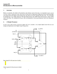
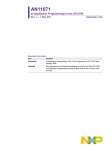
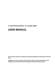
AN10943
Decoding DTMF tones using M3 DSP library FFT function
Rev. 1 — 17 June 2010
Application note
Document information
Info
Content
Keywords
M3, LPC1300, LPC1700, DSP, DFT, FFT, DTMF
Abstract
This application note and associated source code example demonstrates
how to use the FFT function contained within NXP’s M3 DSP library to
decode DTMF tones.
AN10943
NXP Semiconductors
Decoding DTMF tones using M3 DSP library FFT function
Revision history
Rev
Date
Description
1
Initial version
20100617
Contact information
For additional information, please visit: http://www.nxp.com
For sales office addresses, please send an email to: [email protected]
AN10943
Application note
All information provided in this document is subject to legal disclaimers.
Rev. 1 — 17 June 2010
© NXP B.V. 2010. All rights reserved.
2 of 12
AN10943
NXP Semiconductors
Decoding DTMF tones using M3 DSP library FFT function
1. Introduction
The M3 DSP library contains a set of commonly used signal processing functions that
have been designed and optimized for use with the NXP Cortex-M3 LPC1700 and
LPC1300 family of products.
This application note describes, with the aid of a software example, how to use the FFT
(Fast Fourier Transform) function contained within the library to decode DTMF (Dual
Tone Multi Frequency) tones.
Note that the DSP library supplied with application note AN10913[2] must be installed in
order to build the software example.
The application note AN10913 and DSP library can be downloaded at:
http://ics.nxp.com/support/documents/microcontrollers/zip/an10913.zip
2. Overview
This application note demonstrates how the FFT function contained within the NXP M3
DSP Library can be used to decode DTMF tones.
The example software requires the use of a CodeRed RDB1768 development board and
a piece of equipment capable of generating DTMF tones (a PC running tone generating
software is one option).
Tones generated are fed into the RDB1768 board via the Line Input connector. They are
digitized by the codec and transferred to the LPC1768 via the I2S interface. The
Microcontroller uses the FFT function from the DSP library to compute the different
frequencies present in the received data and hence determine the corresponding key.
RDB1768 Development Board
Tone
Generating
Equipment
1
2
LCD
C
o
d
e
c
3
4
5
6
7
8
9
*
0
#
NXP M3 FFT
Demo
LPC1768
180034567*#
Buzzer
DTMF Tone
Fig 1.
System block diagram
The output of the FFT algorithm, and the key corresponding to the tone received, are
displayed on the LCD. Tone received via the codec is output to the buzzer.
AN10943
Application note
All information provided in this document is subject to legal disclaimers.
Rev. 1 — 17 June 2010
© NXP B.V. 2010. All rights reserved.
3 of 12
AN10943
NXP Semiconductors
Decoding DTMF tones using M3 DSP library FFT function
3. Background
3.1 FFT basics
The Discrete Fourier Transform (DFT) is a commonly used transform in communications,
audio signal processing, speech signal processing, instrumentation signal processing,
and image processing. It is a technique used for converting a number of complex values
from the time domain to the frequency domain. The Fast Fourier Transform (FFT) is an
algorithm that is designed to compute the DFT very efficiently. Basically, the FFT is an
algorithm that efficiently computes the frequency content of a discrete set of values, i.e.,
it transforms a time domain signal into the frequency domain.
The result of performing an FFT is a set of points often referred to as ‘bins’. Each point,
or bin, is a complex value that represents a particular part of the frequency spectrum.
The number of points computed (N), and the rate at which the input values were sampled
(fs), determines the range of frequencies represented by each bin (fbin). The exact
relationship is expressed below:
f bin =
fs
N
(1)
For example: if a signal is sampled at 16 kHz and a 16-point FFT is performed, the result
will consist of 16 data points (bins) each representing a frequency spectrum that is 1 kHz
wide. It is important to note that if the input values are real (i.e., the imaginary part is
zero), then only the first N/2+1 bins in the FFT result are independent; the remaining bins
contain no additional information about the input sequence. Because of this, the
maximum frequency present in the results will be half the sampling frequency. The result
of an FFT is often represented as a histogram. See Fig 2 for a histogram that represents
the example described earlier in this paragraph (assumes input sequence is real).
Magnitude
0
Fig 2.
AN10943
Application note
1kHz 2kHz 3kHz 4kHz 5kHz 6kHz 7kHz 8kHz
Example FFT result
All information provided in this document is subject to legal disclaimers.
Rev. 1 — 17 June 2010
© NXP B.V. 2010. All rights reserved.
4 of 12
AN10943
NXP Semiconductors
Decoding DTMF tones using M3 DSP library FFT function
Note that the first FFT output value (bin 0) represents the DC component of the input
sequence.
The input and output values for the FFT function are complex numbers that have the
following form:
a + bi
(2)
For most applications, the input will be a sequence of real values. Therefore, the
imaginary part of the number, b, will be zero. The magnitude (M) and phase relationship
(θ) between the time domain input sequence, and the corresponding bin frequency, can
be calculated from the complex output value as follows:
M = a2 + b2
(3)
( )
(4)
θ = tan −1 b a
3.2 FFT function implementation
The FFT functions contained within the DSP Library operate on 16-bit input values and
produce 16-bit output values. The input and output values are arrays of complex
numbers. The even entries contain the real part of the corresponding complex number
and the odd entries the imaginary part. See Fig 3 for an example.
input_buffer[0] = sample_0_real_part;
input_buffer[1] = sample_0_img_part;
.
.
input_buffer[8] = sample_4_real_part;
input_buffer[9] = sample_4_img_part;
Fig 3.
FFT input buffer format
All FFT functions contained within the DSP Library are Radix-4 implementations. This
means that the number of points computed is a multiple of 4, resulting in 64, 256 and
1024 point FFT functions. Radix-2 implementations, where the number of points is a
multiple of 2, are also common. However, due to the bank of 16 registers present in the
Cortex-M3 core, a Radix-4 implementation offers better performance requiring fewer
CPU cycles to compute the same result.
The FFT functions do not perform calculations “in place”, which means that the input and
output buffers have to be located at different places in memory, i.e., the same buffer
cannot be used to hold both input and output values.
The number of input samples processed is equal to the number of output points
generated. For example, if the 256-point FFT function (vF_dspl_fftR4b16N256) is
used, then 256 input samples are required. These input samples actually consist of 512
different 16-bit data values – 256 real and 256 imaginary. The function then generates
512 16-bit output samples – 256 real and 256 imaginary.
AN10943
Application note
All information provided in this document is subject to legal disclaimers.
Rev. 1 — 17 June 2010
© NXP B.V. 2010. All rights reserved.
5 of 12
AN10943
NXP Semiconductors
Decoding DTMF tones using M3 DSP library FFT function
3.3 DTMF basics
Dual Tone Multi Frequency (DTMF) is a signaling method used by telephones. When a
button is pressed on a telephone keypad, a signal (consisting of two sine waves at
different frequencies) is transmitted to the receiving equipment. Each key uses a unique
combination of two from eight different frequencies (see Fig 4). For example, pressing
the ‘5’ key causes a tone consisting of 770 Hz and 1336 Hz sine waves to be transmitted.
Fig 4.
Tone Frequency
1209 Hz
1336 Hz
1477 Hz
697 Hz
1
2
3
770 Hz
4
5
6
852 Hz
7
8
9
941 Hz
*
0
#
Keypad frequencies
The duration of the tones generated is usually at least 70 ms, however, in some
countries the duration could be as low as 45 ms.
AN10943
Application note
All information provided in this document is subject to legal disclaimers.
Rev. 1 — 17 June 2010
© NXP B.V. 2010. All rights reserved.
6 of 12
AN10943
NXP Semiconductors
Decoding DTMF tones using M3 DSP library FFT function
4. Example software
The example software provided with this application note uses the FFT function to
decode DTMF tones. It takes digitized audio data (input via the line-in connector) from
the codec and performs an FFT on this data. The FFT result is then examined to see if a
tone is present; if so, the results are decoded to determine which key corresponds to this
tone. The software operation is summarized in Fig 5.
Clear Buffer
No
Buffer
Full?
Yes
FFT
Tone
Present?
No
Yes
Decode
Display
Fig 5.
AN10943
Application note
Example software flow chart
All information provided in this document is subject to legal disclaimers.
Rev. 1 — 17 June 2010
© NXP B.V. 2010. All rights reserved.
7 of 12
AN10943
NXP Semiconductors
Decoding DTMF tones using M3 DSP library FFT function
4.1 Sampling audio data
As can be seen from equation (2), the rate at which the audio data is sampled, and the
number of points produced by the FFT algorithm, determines the frequency resolution of
the FFT output. The minimum frequency difference between DTFM tones (73 Hz) defines
the maximum FFT output resolution that can be used in order to differentiate between
tones. To prevent aliasing, the sampling rate must be at least twice the maximum tone
frequency, i.e., it should be at least 2954 Hz.
If audio data is sampled at 8000 Hz, and a 256-point FFT is performed, the resolution of
the output is 31.25 Hz. This is well below the maximum allowable to reliably differentiate
between tones. The time taken to obtain 256 samples when sampling at 8000 Hz is
32 ms, which is well below the minimum tone duration of 70 ms.
The example code uses the codec fitted to all RDB1768 boards to sample audio data
input to the line-in connector. Once a sample has been transferred to the LPC1768, via
the I2S interface, an interrupt is generated. The service routine for this interrupt stores the
sample as the real part of an FFT input value and sets the imaginary part to zero. It also
transmits the received data back to the codec for output via the buzzer.
4.2 FFT
Once the main loop detects that the input buffer is full, a 256 point FFT is performed on
the received data. The magnitudes of the complex results generated by the FFT are then
calculated using equation (3). However, for efficiency the software only calculates the
magnitude squared, i.e., the square root operation is not performed. The magnitude
squared value roughly corresponds to the power present at a particular frequency and is
therefore an adequate value for the purpose of tone detection and decoding.
When sampling at 8000 Hz and performing a 256-point FFT, frequencies present in
DTMF tones will appear in 7 different output bins (see Table 1).
Table 1.
DTMF tone - FFT bin table
Frequency
Bin number
697 Hz
22
770 Hz
25
852 Hz
27
941 Hz
30
1209 Hz
39
1336 Hz
43
1477 Hz
47
1633 Hz
52
4.3 Tone detection
In order to detect if a tone is present the power in the bins corresponding to the DTMF
frequencies is compared to the total power present across all bins. If the power in the
DTMF bins is found to be 25 % higher than the total power a tone is assumed to be
present.
AN10943
Application note
All information provided in this document is subject to legal disclaimers.
Rev. 1 — 17 June 2010
© NXP B.V. 2010. All rights reserved.
8 of 12
AN10943
NXP Semiconductors
Decoding DTMF tones using M3 DSP library FFT function
4.4 Decoding audio data
In order to determine which tone is present only the relative magnitude of the bins listed
in Table 1 need to be compared. If a tone is present then two of the bins should contain
values that are higher than the others. One group of these bins represents the row and
another group the column, see Table 2.
Table 2.
Key
FFT bin - Key table
Row bin
Column bin
1
22
39
2
22
43
3
22
47
4
25
39
5
25
43
6
25
47
7
27
39
8
27
43
9
27
47
*
30
39
0
30
43
#
30
47
Decoding which key has been pressed is simply a matter of determining which bins in the
row (22, 25, 27, 30) and column (39, 43, 47) groups contain the largest value. These
values can then be used to obtain the key from a look up table.
4.5 Displaying results
After a DTMF tone has been detected and decoded, the corresponding key and the
results of the FFT are displayed on the LCD. The magnitude of each bin is displayed and
is scaled to fit the available area.
4.6 Hardware setup
The example software is designed to run on a CodeRed RDB1768 Evaluation board, the
following versions of this board are supported:
• RDB1768 Revision 1
• RDB1768 Revision 2
Tones should be input via the 3.5mm Line-In jack (J16). All received audio data is output
on the buzzer (ensure that S2 is configured as follows – 1 off, 2 on).
AN10943
Application note
All information provided in this document is subject to legal disclaimers.
Rev. 1 — 17 June 2010
© NXP B.V. 2010. All rights reserved.
9 of 12
AN10943
NXP Semiconductors
Decoding DTMF tones using M3 DSP library FFT function
5. References
AN10943
Application note
[1]
Understanding Digital Signal Processing by Richard G. Lyons
[2]
DSP library for LPC1700 and LPC1300 (AN10913)
[3]
LPC17xx User Manual (UM10360)
[4]
Dual-tone multi-frequency signaling, Wikipedia
(http://www.nxp.com/redirect/en.wikipedia.org/wiki/Dual-tone_multifrequency_signaling)
All information provided in this document is subject to legal disclaimers.
Rev. 1 — 17 June 2010
© NXP B.V. 2010. All rights reserved.
10 of 12
AN10943
NXP Semiconductors
Decoding DTMF tones using M3 DSP library FFT function
6. Legal information
NXP Semiconductors products in such equipment or applications and
therefore such inclusion and/or use is at the customer’s own risk.
6.1 Definitions
Draft — The document is a draft version only. The content is still under
internal review and subject to formal approval, which may result in
modifications or additions. NXP Semiconductors does not give any
representations or warranties as to the accuracy or completeness of
information included herein and shall have no liability for the consequences
of use of such information.
6.2 Disclaimers
Limited warranty and liability — Information in this document is believed to
be accurate and reliable. However, NXP Semiconductors does not give any
representations or warranties, expressed or implied, as to the accuracy or
completeness of such information and shall have no liability for the
consequences of use of such information.
In no event shall NXP Semiconductors be liable for any indirect, incidental,
punitive, special or consequential damages (including - without limitation lost profits, lost savings, business interruption, costs related to the removal
or replacement of any products or rework charges) whether or not such
damages are based on tort (including negligence), warranty, breach of
contract or any other legal theory.
Notwithstanding any damages that customer might incur for any reason
whatsoever, NXP Semiconductors’ aggregate and cumulative liability
towards customer for the products described herein shall be limited in
accordance with the Terms and conditions of commercial sale of NXP
Semiconductors.
Right to make changes — NXP Semiconductors reserves the right to make
changes to information published in this document, including without
limitation specifications and product descriptions, at any time and without
notice. This document supersedes and replaces all information supplied prior
to the publication hereof.
Applications — Applications that are described herein for any of these
products are for illustrative purposes only. NXP Semiconductors makes no
representation or warranty that such applications will be suitable for the
specified use without further testing or modification.
Customers are responsible for the design and operation of their applications
and products using NXP Semiconductors products, and NXP
Semiconductors accepts no liability for any assistance with applications or
customer product design. It is customer’s sole responsibility to determine
whether the NXP Semiconductors product is suitable and fit for the
customer’s applications and products planned, as well as for the planned
application and use of customer’s third party customer(s). Customers should
provide appropriate design and operating safeguards to minimize the risks
associated with their applications and products.
NXP Semiconductors does not accept any liability related to any default,
damage, costs or problem which is based on any weakness or default in the
customer’s applications or products, or the application or use by customer’s
third party customer(s). Customer is responsible for doing all necessary
testing for the customer’s applications and products using NXP
Semiconductors products in order to avoid a default of the applications and
the products or of the application or use by customer’s third party
customer(s). NXP does not accept any liability in this respect.
Export control — This document as well as the item(s) described herein
may be subject to export control regulations. Export might require a prior
authorization from national authorities.
6.3 Trademarks
Notice: All referenced brands, product names, service names and
trademarks are property of their respective owners.
Suitability for use — NXP Semiconductors products are not designed,
authorized or warranted to be suitable for use in life support, life-critical or
safety-critical systems or equipment, nor in applications where failure or
malfunction of an NXP Semiconductors product can reasonably be expected
to result in personal injury, death or severe property or environmental
damage. NXP Semiconductors accepts no liability for inclusion and/or use of
AN10943
Application note
All information provided in this document is subject to legal disclaimers.
Rev. 1 — 17 June 2010
© NXP B.V. 2010. All rights reserved.
11 of 12
AN10943
NXP Semiconductors
Decoding DTMF tones using M3 DSP library FFT function
7. Contents
1.
2.
3.
3.1
3.2
3.3
4.
4.1
4.2
4.3
4.4
4.5
4.6
5.
6.
6.1
6.2
6.3
7.
Introduction .........................................................3
Overview ..............................................................3
Background .........................................................4
FFT basics .........................................................4
FFT function implementation..............................5
DTMF basics ......................................................6
Example software................................................7
Sampling audio data ..........................................8
FFT ....................................................................8
Tone detection ...................................................8
Decoding audio data ..........................................9
Displaying results ...............................................9
Hardware setup..................................................9
References .........................................................10
Legal information ..............................................11
Definitions ........................................................11
Disclaimers.......................................................11
Trademarks ......................................................11
Contents.............................................................12
Please be aware that important notices concerning this document and the product(s)
described herein, have been included in the section 'Legal information'.
© NXP B.V. 2010.
All rights reserved.
For more information, please visit: http://www.nxp.com
For sales office addresses, please send an please send an email to:
[email protected]
Date of release: 17 June 2010
Document identifier: AN10943