1
22nd December, 2010
LPC1768 UART programming v.1
MINIMAL NETWORK ELEMENT III
LPC1768 UART programing
Version 1.0
Huy Nguyen
Team Members
Bikash Shakya (15 ECTS)
Coaches
Huy Nguyen (15 ECTS)
Bernt Sundström
Markku Antikainen (24 ECTS)
Hans Eriksson
Mudassir Asif (24 ECTS)
Robert Olsson
Muhammad Ziad (24 ECTS)
Naresh Kumar Khatri (24 ECTS)
Champion
Siddharth Sharma (15 ECTS)
Björn Pehrson
22nd December, 2010
1
22nd December, 2010
LPC1768 UART programming v.1
History
Date
Version
Modification
22nd December, 2010
1
Created
2
22nd December, 2010
LPC1768 UART programming v.1
Table of Contents
I. UART................................................................................................................................................4
I.1. Introduction...............................................................................................................................4
I.2. Communication Error ...............................................................................................................4
I.3. UART Pin Connection...............................................................................................................5
II. Minicom...........................................................................................................................................5
III. UART programming.......................................................................................................................8
III.1. Setup the UART......................................................................................................................8
III.2. Writing the interrupt handler function....................................................................................9
IV. Project's UART Program................................................................................................................9
IV.1. Data structure..........................................................................................................................9
IV.2. Facility functions...................................................................................................................10
Reference............................................................................................................................................12
3
22nd December, 2010
LPC1768 UART programming v.1
I. UART
I.1. Introduction
The UART, universal asynchronous receiver / transmitter, is mainly used for the
communication between computer systems. The communication can be in full duplex mode or half
duplex mode. At the sender side, the data is given to the UART in bytes and the UART then
transmits them as sequential individual bits. At the receiver side, the sequential bits received from
the serial link are assembled into bytes and placed into the receiver register waiting for reading. To
perform the function of converting between serial and parallel form, shift registers are used in the
UART. The UART is of the asynchronous transmission type which means that there is no clock
signal between the two communicated parties, instead the communication configuration (speed,
number of data bits, parity bit or not, number of stop bits) is agreed in advance and special bits for
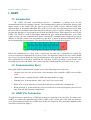
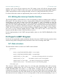
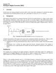
the synchronization are transmitted. The character framing of it is showed in figure 1:
Figure 1: UART character framing (reproduced from [1])
Before the transmission of a data word, a special bit, the start bit, is transmitted to inform the
receiver and also to synchronize the receiver's clock. The difference between the two clocks should
not exceed 10 percent during the data bit transmissions. After that, the data bits are sent from the
least significant bit to the most significant bit. And then, a parity bit which is used for the error
checking may be sent and finally, one or more stop bits, which signal the end of the word, is sent.
I.2. Communication Error
During the UART communication session, some of the following errors may occur:
•
Overrun error: the error occurs when a new character arrives and the UART receiver buffer
is full.
•
Underrun error: it signals that the UART transmitter buffer is empty
•
Framing error: it means that the "start" and "stop" bits are not valid.
•
Parity error: it is set when the received parity bit does not match the calculated one.
•
Break interrupt: it is held when the received serial line is in the spacing state (all zeros) for
more than one full character transmission.
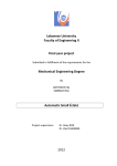
I.3. UART Pin Connection
To send and receive data, the two UART ports must be connected by a serial link. To connect two
UARTs, we connect the transmitter pin of this UART to the receiver pin of the other pin and vice
versa. The ground pin of the two UARTs also need to be connected. The connection diagram of the
serial link is showed in figure 2.
4
22nd December, 2010
LPC1768 UART programming v.1
Figure 2: UART pin connection
II. Minicom
A very useful application when programming with UART is the serial communication application.
It allows us to send the data to the UART and receive the data back which plays a very important
role in debugging. A popular serial communication program is minicom. In Ubuntu, minicom can
be installed using the following command:
sudo apt-get install minicom
To use minicom, we need to first configure it by using the below command:
sudo minicom -s
The following interface is displayed:
Figure 3: Minicom configuration interface
First, we need to setup the serial port by choosing "Serial port setup":
5
22nd December, 2010
LPC1768 UART programming v.1
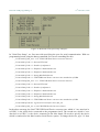
Figure 4: Minicom serial port setup interface
In "Serial Port Setup", we first start with specifying the port for serial communication. With our
programming board, using the dmesg command you can see something like this:
[11149.865325] ftdi_sio 2-1:1.0: FTDI USB Serial Device converter detected
[11149.865413] usb 2-1: Detected FT2232C
[11149.865415] usb 2-1: Number of endpoints 2
[11149.865416] usb 2-1: Endpoint 1 MaxPacketSize 64
[11149.865418] usb 2-1: Endpoint 2 MaxPacketSize 64
[11149.865419] usb 2-1: Setting MaxPacketSize 64
[11149.871488] usb 2-1: FTDI USB Serial Device converter now attached to ttyUSB0
[11149.871498] ftdi_sio 2-1:1.1: FTDI USB Serial Device converter detected
[11149.872001] usb 2-1: Detected FT2232C
[11149.872001] usb 2-1: Number of endpoints 2
[11149.872001] usb 2-1: Endpoint 1 MaxPacketSize 64
[11149.872001] usb 2-1: Endpoint 2 MaxPacketSize 64
[11149.872001] usb 2-1: Setting MaxPacketSize 64
[11149.878268] usb 2-1: FTDI USB Serial Device converter now attached to ttyUSB1
[11149.878450] usbcore: registered new interface driver ftdi_sio
[11149.878452] ftdi_sio: v1.6.0:USB FTDI Serial Converters Driver
In the above message, the first FTDI USB Serial Device converter one, which is "now attached to
ttyUSB0", is the serial device connected to the programmer itself. The second one, which is "now
attached to ttyUSB1", is the device connected to the blue board. We need to specify the device
which is connected to the blue board to Serial Device option. To change the device, type "A" then
6
22nd December, 2010
LPC1768 UART programming v.1
type the device, for example: /dev/ttyUSB1 and press Enter.
Next, we need to configure the transmission speed, the number of data bit, parity and the number of
stop bits. We do it by type "E" then type the character corresponding to the options we want. Type
Enter when finish.
Figure 5: Communication parameter setting interface
Then type F to change "Hardware flow control" to "no". And press Enter to exit to the main setting
interface.
After setting, we need to save it so we do not to do the setup next time. Choose "Save setup as dfl"
to save this setting as the default setting. Choose "Save setup as ..." to save the setting to another
file.
Now, choose "Exit from Minicom" to exit it and then start it again with the following command:
minicom -o
The -o option is used to disable the initialization which can bring undesirable result in our case.
With this command, minicom will use the setting from the default configuration file. To use a
difference configuration file, specify the filename as argument when start minicom:
minicom -o configuration_file
We can also override any setting in the configuration file using the command line options. For the
list of available options, please see the Linux minicom man page [2] or minicom's readme file.
To quit minicom, press Ctrl-A and then press Q.
We can also setting the minicom on the fly when running by press Ctrl-A and then O. This will
bring the minicom's main configuration interface.
7
22nd December, 2010
LPC1768 UART programming v.1
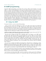
III. UART programming
To do the UART programming, we basically need to do two things. The first thing is set up the
UART (i.e enable it, setting parameters such as speed, number of data bits, parity bit or not and
number of stop bit). The second thing is providing an interrupt handler function to manage it, i.e
specify what to do when there is data to receive, when there is no data to transmit and when there
are errors, and register this function with the system so that the system knows which function to call
when the UART associated events occur. The register is quite simple. We just need to put a pointer
to that function in the defined place for UART in the system interrupt vector. However, in our case,
an interrupt vector with dummy interrupt handlers for most cases have been provided, so what we
need to do is that figure out the name of the interrupt handler function, which can be one of
UART0_IRQHandler, UART1_IRQHandler, UART2_IRQHandler or UART3_IRQHandler, and use
the same name for our interrupt handler function. Our defined function will override the dummy
function. For the list of all provided dummy function, see the file LPC1768_handlers.c.
III.1. Setup the UART
To setup the UART, we need to do the following things:
- First, we need to choose the UART port we want to use, figure out its pins for receiving and
transmitting, and set up the pin for UART using the pins' control register. Because the LPC1768
have four UART ports, from port 0 to port 3, and associating with each port is a pair of transmitter
and receiver pins so we need to find out which are the pins for our desire port. Beside that, since
each pin in the LPC1768 may have several different functions and different modes, we also have to
configure the pin so that they are suitable to be used for the UART.
- Second, we need to enable the power for our port via the PCONP register because the LPC1768
allows us to disable power to unused peripherals for power saving.
- Our next step is setting the clock. This is important since it will relate to our UART speed
calculation later. The clock for UART is derived from the CPU clock (CCLK) so we need to know
the speed of the CPU clock before deciding the UART clock value. The CPU clock can be setting
using the Clock Source Select register (CLKSRCSEL) and Phase Locked Loop 0 (PLL0). In our
case, the internal clock of the LPC1768, which has the speed of 4Mhz, is used for the CPU. The
values of the UART clock can be CCLK, CCLK/2, CCLK/4 and CCLK/8. The desirable value can
be choose by writing the appropriate value to the Peripheral clock selection register (PCLKSEL0
and PCLKSEL1).
- Now, it's time to configure the UART speed, the baud rate. The baud rate is configured by writing
appropriate values the the ports' Divisor Latch LSB register (DLL), Divisor Latch MSB register
(DLM) and Fractional Divider Register (FDR). For detail on how to calculate these values, please
refer to section 14.4.12 of the LPC1768 user manual [3]. Note that in order to be able to access
these registers, we need first to set the DLAB bit of the Line Control Register (LCR) to 1.
- Next, we will choose the format of the character when transmitting (the number of data bits, parity
and the number of stop bits) using the Line Control Register (LCR). We also choose to use the FIFO
buffer (16 bytes) or not via the FIFO Control Register (FCR).
- Our last step is to decide which UART events to be enabled (i.e which events for this UART port
will cause the interrupt handler function to be called) and enable the UART interrupt in the NVIC
8
22nd December, 2010
LPC1768 UART programming v.1
register so the events will be reported to the CPU which in turn will call the interrupt handler
function. The types of UART events can be seen and enabled from the Interrupt Enable Register
(IER). Also note that in order to change the IER, we have to set the DLAB bit of the LCR to 0.
For detail of how these tasks are implemented, please see the UART_init function of the uart.c.
III.2. Writing the interrupt handler function
The interrupt handler is called when the events corresponding to what are enabled in the UART port
IER register. The only things we need to concern when writing the interrupt handler is its name,
which must be the same as what in the LPC1768_handlers.c, and to remember to clear the
corresponding interrupt flag if it does not clear automatically. A good practice in the development
phase is to use a led to signal when there is an interrupt. The event which causes the interrupt can be
identified using the Interrupt Identification Register (IIR) together with the Line Status Register
(LSR). The received data can be read from the Receiver Buffer Register (RBR). To transmit data,
just write it to the Transmit Holding Register (THR). Note that in order to access these two
registers, the DLAB bit of the LCR also need to be set to 0.
For the implementation of the UART interrupt handler, please see the UART0_IRQHandler of the
file uart.c.
IV. Project's UART Program
Beside the interrupt handler and the initialized function, the project UART code also contains a data
structure along with its managed facility functions for the ease of working with UART.
IV.1. Data structure
The data structure which is used in our UART is showed below:
typedef struct
{
uint8_t rx_buf[UART_BUFFER_SIZE]; // receive buffer
uint8_t tx_buf[UART_BUFFER_SIZE]; // transmit buffer
volatile uint16_t rx_start_index;
volatile uint16_t rx_len;
// the index of starting index for received byte
// the number of bytes in the receiving buffer
volatile uint16_t tx_start_index; // the index of starting byte for transmitting
volatile uint16_t tx_len; // the number of bytes in the transmitting buffer
} uart_buffer_type;
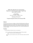
This structure defines two buffer arrays for receiving and transmitting data with necessary
information to manage them. The size of both arrays is 256 bytes and can be changed via the
UART_BUFFER_SIZE. The buffer is a round buffer, meaning that the data will be store
continuously from index the beginning to the end of the array and then back to the beginning. Each
array has two parameters, the start_index and the len. The start_index tells us the array index of the
data that has not been reading in case of receiving buffer or has not been transmitting in case of
9
22nd December, 2010
LPC1768 UART programming v.1
transmitting buffer. The len parameter indicates how many data left.
Figure 6: UART array buffer
When the UART receives data from the serial link, it will read them from the receive FIFO and
store them in the receiving buffer after the current unprocessed receiving data. When system wants
to transmit data using the UART, the data will be first written to the transmitting buffer. When the
UART sees that its transmit FIFO is empty, it will try to fill the transmit FIFO by reading from the
transmitting buffer. For more detail, please consult the UART interrupt handler function in the
uart.c.
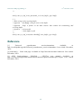
IV.2. Facility functions
The facility functions are mostly associated with handling the buffer arrays. Their definitions and
short descriptions are listed below. For detail of each function, please consult the function code in
the uart.c:
/**
* write data to the transmitting fifo
* change this function for different behaviours
* @param *buff a pointer to the data structer that contain the transmitting and
receiving buffer
* @param number_of_byte
the number of byte to send
*/
void uart_send(uart_buffer_type *buff, uint8_t number_of_byte, uint8_t uart_num);
/* *
* Write string to the transmitting buffer
* @param charBuff[]: string to write to the buffer
* @param *buff: a pointer to the data structer that contain the transmitting and
receiving buffer
* @return
0 if sucessful
*
1 if the buffer is full
*/
10
22nd December, 2010
LPC1768 UART programming v.1
uint8_t uart_tx_buf_write(char charBuf[], uart_buffer_type *buff);
/* *
* Write byte ch to the transmitting buffer
* @param ch: byte to write to the buffer
* @param *buff: a pointer to the data structer that contain the transmitting and
receiving buffer
* @return
0 if sucessful
*
1 if the buffer is full
*/
uint8_t uart_tx_buf_write_byte(uint8_t ch, uart_buffer_type *buff);
/* *
* Read byte from the receiving buffer. The character will be deleted from the receiving
buffer.
* @param *buff: a pointer to the data structer that contain the transmitting and
receiving buffer
* @return
0 if no character. So, in order to use the function, may be should check the
length of the receiving buffer first
*
in case the buffer can contains '\0';
*
the first character in the buffer
*/
uint8_t uart_rx_buf_read_byte(uart_buffer_type *buff);
/* *
* Read number of bytes from the receiving buffer. The characters will be deleted from the
receiving buffer.
* @param *buff: a pointer to the data structer that contain the transmitting and
receiving buffer
* @param *result: a pointer to a place to contain the results
* @param number_of_byte: the number of bytes to read
* @return
the number of character that actually read.
*/
uint8_t uart_rx_buf_read(uart_buffer_type *buff, uint8_t *result, uint8_t number_of_byte);
/* *
* Write byte ch to the receiving buffer
* @param ch: byte to write to the buffer
* @param *buff: a pointer to the data structer that contain the transmitting and
receiving buffer
* @return
0 if sucessful
*
1 if the buffer is full
11
22nd December, 2010
LPC1768 UART programming v.1
*/
uint8_t uart_rx_buf_write_byte(uint8_t ch, uart_buffer_type *buff);
/* *
* Write string to the receiving buffer
* @param charBuff[]: string to write to the buffer
* @param *buff: a pointer to the data structer that contain the transmitting and
receiving buffer
* @return
0 if sucessful
*
1 if the buffer is full
*/
uint8_t uart_rx_buf_write(char charBuf[], uart_buffer_type *buff);
Reference
[1]
Universal
asynchronous
receiver/transmitter.
Available
at:
http://en.wikipedia.org/wiki/Universal_asynchronous_receiver/transmitter. Last visited: December,
2010.
[2] minicom(1) - Linux man page. Available at: http://linux.die.net/man/1/minicom. Last visited:
December, 2010.
[3] NXP Semiconductors. UM10360 - LPC17xx user manual. Available at:
http://ics.nxp.com/support/documents/microcontrollers/pdf/user.manual.lpc17xx.pdf. Last visited:
December, 2010.
12