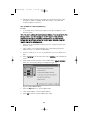
1
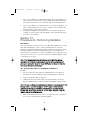
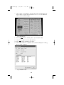
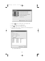
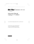
4110185B.qxp
9/25/2007
11:55 AM
Page CVR1
Instruction Manual
Catalog # 171-203001
For use with Bio-Plex Manager™ software version 5.0 and higher with
MCV plate IV, or for use with Bio-Plex Manager software 4.0/4.1 with
MCV plate III.
For technical support, contact your local Bio-Rad office or,
in the US, call 1-800-4BIORAD (1-800-424-6723)
For research use only. Not for diagnostic procedures.
4110185B.qxp
9/25/2007
11:55 AM
Page I
Table of Contents
Section 1
Introduction . . . . . . . . . . . . . . . . . . . . . . . . . . . . . . . .1
Section 2
Product Description . . . . . . . . . . . . . . . . . . . . . . . . . .2
Section 3
Specifications . . . . . . . . . . . . . . . . . . . . . . . . . . . . . . .3
Section 4
Storage and Handling . . . . . . . . . . . . . . . . . . . . . . . . .3
Section 5
Principle of Optics Validation . . . . . . . . . . . . . . . . . . .3
Section 6
Principle of Reporter Validation . . . . . . . . . . . . . . . . .4
Section 7
Principle of Classify Validation . . . . . . . . . . . . . . . . . .7
Section 8
Principle of Fluidics Validation . . . . . . . . . . . . . . . . . .8
Section 9
Software Utility Installation . . . . . . . . . . . . . . . . . . . .8
Section 10
Procedure for Performing Validation . . . . . . . . . . . . .9
10.1
One-Step Procedure for all Validation Parameters . . . . . . . . . .9
10.2
Validation of Optics Alignment . . . . . . . . . . . . . . . . . . . . . . . .12
10.3
Validation of Fluidics Integrity . . . . . . . . . . . . . . . . . . . . . . . .14
10.4
Validation of Reporter Channel Performance . . . . . . . . . . . . .15
10.5
Validation of Classify Efficiency . . . . . . . . . . . . . . . . . . . . . . .17
10.6
Generating a Validation Report . . . . . . . . . . . . . . . . . . . . . . .18
10.7
Validation Kit Report Form Example . . . . . . . . . . . . . . . . . . .19
Section 11
Troubleshooting Guide . . . . . . . . . . . . . . . . . . . . . . .21
Section 12
Ordering Information . . . . . . . . . . . . . . . . . . . . . . . .21
Section 13
Reference . . . . . . . . . . . . . . . . . . . . . . . . . . . . . . . . .22
4110185B.qxp
9/25/2007
11:55 AM
Page 1
Section 1
Introduction
Qualification of analytical instruments is a formal process of documenting that an
instrument is fit for its intended use and that it is kept maintained and calibrated.
The Bio-Plex® validation kit is used for operational qualification (OQ) of the Bio-Plex
suspension array system. The validation kit is designed to validate the operation of
all of the primary components of the system and is a valuable tool that allows the
user to discriminate between assay and instrumentation problems.
The Bio-Plex validation kit consists of beads to evaluate the following components
of the Bio-Plex suspension array system: 1) optics alignment, 2) integrity of fluidics,
3) reporter channel performance, and 4) classify efficiency. A brief definition of the
parameter and the principle of each procedure is described, along with complete
procedures for evaluating each of the primary components. An explanation of the
potential impact of each process on a typical Bio-Plex cytokine assay is included to
assist the user in assay troubleshooting and development.
1
4110185B.qxp
9/25/2007
11:55 AM
Page 2
Section 2
Product Description
The following reagents are included in the Bio-Plex® validation kit 4.0:
Reagent
Optics validation bead set:
Optics beads 1 and 2
(1x10⁵ beads/ml)
Quantity
2 x 10 ml black bottles
Fluidics validation bead set:
Fluidics bead 1 and 2
(1x10⁵ beads/ml)
2 x 10 ml black bottles
Reporter validation bead set:
Reporter blank, 1, 2, 3, 4, 5, and 6
(1x10⁵ beads/ml)
6 x 10 ml white bottles
Classify validation bead set:
Classify bead A(1), B(4), C(40), D(54), E(100)
(1x10⁵ beads/ml)
5 x 10 ml black bottles
Note: The Bio-Plex validation kit also includes a BizCard CD, which contains lotspecific product specifications.
The following materials are required but not supplied:
Bio-Plex MCV plates
Bio-Rad catalog #171-203032, MCV plate III, for use with Bio-Plex Manager
4.0/4.1 (standard or security software)
Bio-Rad catalog #171-203033, MCV plate IV, for use with Bio-Plex Manager 5.0
and later (standard or security software)
Bio-Plex Suspension Array System
Bio-Rad catalog #171-000001, 171-000002, 171-000003, 171-00004,
171-000005, 171-000006, 171-000007, or 171-000009
Bio-Plex Calibration Kit
Bio-Rad catalog #171-203060, includes Cal1 and Cal2 calibration beads for
approximately 50 daily calibration routines
mini vortexer
sterile distilled water
70% isopropanol
10% bleach
bulb pipets
2
4110185B.qxp
9/25/2007
11:55 AM
Page 3
Section 3
Specifications
Specifications for the Bio-Plex® validation kit may differ from lot to lot. Please refer
to the package insert provided with your validation kit for specifications.
Section for Software Installation
The Bio-Plex validation kit 4.0 includes a BizCard CD containing files with the
specifications for the validation beads along with additional information. The file
information is automatically loaded into Bio-Plex Manager™ 4.0 and later versions
upon installation.
Section 4
Storage and Handling
The Bio-Plex® validation kit beads are stable if stored at 4°C protected from light.
When using the Bio-Plex validation kit, remove beads from storage and dispense
into the MCV plate. Return to 4°C storage immediately following use to preserve
shelf life. All components are guaranteed for 18 months from the date of
manufacture when stored as specified in this manual.
Section 5
Principle of Optics Validation
Principle
The Bio-Plex® array reader is a laser-based fluorescence detection system
containing sensitive optics components. Alignment of the laser/optics system is
critical for optimal instrument performance. A method for the assessment of the
optics alignment is included in the validation kit. Acceptable specifications for the
alignment procedure are listed in the product insert.
Impact on Assay Performance
The alignment of the optics bench of the Bio-Plex array reader is critical for proper
assay performance. Misalignment of the reporter optics path can result in 1)
reduced assay sensitivity or 2) poor well-to-well assay precision. Misalignment of
the classification optics path can lead to 1) increased read times or 2)
misclassification of one assay into another, leading to false positive or negative
results. Correlation studies have been performed to determine the direct effect of
misalignment on assay performance.
3
4110185B.qxp
9/25/2007
11:55 AM
Page 4
Section 6
Principle of Reporter Validation
Principle
The reporter (RP1) channel is the fluorescence channel used for assay quantitation
(See Bio-Plex® system hardware manual for more information regarding the
principle of Bio-Plex technology). Therefore, validation of this component of the
Bio-Plex system is a critical part of operational qualification. R-phycoerythrin (R-PE)
is the primary reporter molecule used in Bio-Plex assays. A series of beads dyed
with varying intensities of a fluorochrome spectrally matched to R-phycoerythrin are
used for this procedure.
The primary reporter channel performance parameters are as follows: dynamic
range, linearity, slope, accuracy, and instrument threshold (sensitivity) of the reporter
channel response. Each of these parameters is related directly to the performance
of the Bio-Plex array reader and has defined acceptable specifications. Definitions
for the parameters and the applicability to a typical assay performed on the
Bio-Plex array reader are listed below. If any of the parameters are not within the
specified range, contact Bio-Rad technical support for assistance.
High Versus Low PMT Calibration and Validation
Some assays may require quantitating a range of analyte concentrations greater
than what can be achieved running the instrument at a single PMT setting. In these
cases, the samples may be run with different detector channel PMT settings: a high
RP1 target setting and a low RP1 target setting. They are set differently depending
on your version of Bio-Plex Manager™ software.
For Bio-Plex Manager 4.0/4.1, the targets are set during calibration of the
instrument. Using the high RP1 target will allow for the ability to quantitate lower
concentrations of analyte, while using the low RP1 target allows for the ability to
quantitate higher concentrations of analyte. For Bio-Plex Manager 5.0 and later,
calibration is performed using the low RP1 target and the high RP1 target is then
selected during the validation setup.
Dynamic Range of Reporter Channel
Definition
The theoretical maximum dynamic range of the Bio-Plex array reader can be
represented by the maximum number of channels in the A/D converter. Currently,
the available range of channels is from 0 to 32,767, or about 4.5 decades on a log
scale. These channels are represented by FI, or Fluorescence Intensity units. The
dynamic range of the Bio-Plex array reader is measured by taking the log of the
fluorescence intensity value of the highest reporter bead minus the fluorescence
intensity of the blank bead. This value is the calibrated dynamic range of the
instrument and is always less than 4.5 log decades because the highest intensity
bead in the validation kit that is read is less than 32,767 FI units, while the blank
bead gives a reading that is greater than zero FI units.
4
4110185B.qxp
9/25/2007
11:55 AM
Page 5
Impact on Assay Performance
It is desirable for the range of the instrument to be greater than the range of the
assay. In most experiments, the dynamic range of the assay is far less than that of
the instrument. However, in some assays, the same or different analytes may be
present in greater than 4.5 log differences in concentration. When this is the case,
the sample can be rerun at different PMT settings to extend the overall dynamic
range of the measurements.
Linearity of Reporter Channel
Definition
The reporter validation bead set is utilized to construct a plot where the reporter
channel median fluorescence intensity values are plotted against the corresponding
expected fluorescent intensity values (as determined on an independent calibrated
instrument). Instrument linearity is expressed as the coefficient of determination or
R-squared (R2) value.
Impact on Assay Performance
The linearity of the instrument response may directly affect a typical standard or
calibration curve in a Bio-Plex assay, thereby impacting the unknown values
extrapolated from that curve. If the R2 value is not within acceptable limits, it may
be necessary to realign the optics or check the response of the reporter
photomultiplier tube.
Accuracy of Reporter Channel Response
Definition
The accuracy of the reporter channel response is a more stringent measurement of
the linearity than the R2 value. Simply stated, the accuracy of the reporter channel
response is the percent difference that the regression line is away from the
expected fluorescence intensity data point values.
Impact on Assay Performance
Since accuracy is also a measurement of the linearity of the instrument response,
the same principles that apply to linearity also apply to accuracy of the reporter
channel response. The accuracy data is evaluated in combination with optics
alignment to determine if the Bio-Plex reader will perform according to
specifications. It is possible for the accuracy value to fall out of specification before
the linearity parameter. This is expected due to the fact that the accuracy parameter
is a more sensitive measurement of linearity than the R2 value. These data are
correlated with optics alignment data as well as assay performance to determine
when the array reader will not perform according to specifications.
Slope of the Reporter Channel Response
Definition
The slope of the regression line resulting from the plotting of reporter channel mean
fluorescent values against expected relative fluorescence is related to the dynamic
range of the instrument. The slope of the regression line is a function of the
response of the reporter channel photomultiplier tube.
5
4110185B.qxp
9/25/2007
11:55 AM
Page 6
Impact on Assay Performance
The slope of the regression line is directly related to the dynamic range of the
instrument. The slope yields direct information about the response of the
photomultiplier tube. If the photomultiplier tube signal saturates at low
fluorescence values, the dynamic range of the instrument is affected. The slope
of the line impacts the dynamic range and the range, in turn, impacts the
quantifiable range of an assay.
Instrument Threshold (Sensitivity)
Definition
Every instrument has an inherent level of background noise. Noise can be
attributed to the laser, the PMT, the amplification electronics or the fluidics. The
instrument threshold (sensitivity) of the Bio-Plex array reader is one way to
demonstrate noise of the system. It is defined as the reporter channel signal of a
blank bead that contains no reporter dye.
Impact on Assay Performance
The instrument threshold level demonstrated using the Bio-Plex validation kit is a
low fluorescence intensity value. The typical background or zero standard of a
Bio-Plex cytokine assay falls at a median fluorescence intensity of ~100. This is a
desired result, as the instrument threshold should not limit the assay sensitivity. If
the instrument threshold is too close to zero, then a low assay signal may be
masked; if too high, then the linearity and dynamic range may be compromised.
6
4110185B.qxp
9/25/2007
11:55 AM
Page 7
Section 7
Principle of Classify Validation
Principle
Bio-Plex® technology relies on the ability of the Bio-Plex array reader to
discriminate between assay beads impregnated with varying ratios of 2
fluorescent dyes. This is the concept whereby multiplexing within a single well
may occur. The periodic evaluation of the classify efficiency is necessary to
complete the Bio-Plex array reader qualification process. A series of beads with
varying ratios of the classification dyes are analyzed on the Bio-Plex array reader
and the efficiency of multiplexing is quantitated. A classify efficiency of >80% is
required for optimal results. Doublet Discriminator (DD) efficiency is a measure of
the percentage of the classify beads that fall within the DD gates. The DD gates
are used to distinguish single beads from bead clusters, bead fragments or other
small particles passing in front of the detector. Greater than 75% of the beads
should fall within the gates for optimal results.
Impact on Assay Performance
Inefficient classification of beads may have several potential effects on an assay. If
a bead region exhibits a classify efficiency of less than 80%, the read time of a
96-well plate may be increased. The Bio-Plex array reader tabulates a specified
number of defined events in each region for each well sampled. If the percentage
of beads within a specific region is low, the time required to count is increased,
therefore the total time to read an entire plate is prolonged. Extremely prolonged
assay read times could impact well-to-well precision, since the kinetics of a
sandwich assay, for example, are not 100% stable over a period of several hours.
Another potential impact of inefficient classification is the misclassification of one
assay bead into another bead region. This could yield false positive or negative
results for a particular assay. A DD efficiency of less than 75% may increase the
read time of the assay and affect results in the same manner as a low classify
efficiency.
7
4110185B.qxp
9/25/2007
11:55 AM
Page 8
Section 8
Principle of Fluidics Validation
Principle
The fluidics system of the Bio-Plex® array reader requires routine maintenance to
prevent clogging and other malfunctions. Strict adherence to the maintenance
procedures is mandatory for optimal instrument performance. An assessment of
the integrity of the fluidics is automatically performed in the fluidics validation
procedure. In the fluidics validation test, a sample of beads is analyzed followed
by a sample of buffer to assess the carryover of beads from one well to another.
This procedure should be performed once per week to ensure that assay results
are not adversely affected. The fluidics path, including the sample needle, must
be completely free of debris and excess beads for optimal array reader
performance.
Impact on Assay Performance
If a system is exhibiting a high level of carryover due to valve malfunction or a
partially clogged sample needle, a significant percentage of beads may be carried
over from one well to another. This phenomenon may adversely affect the median
fluorescent intensity values. For example, if a well with a high median fluorescent
intensity (FI) is read immediately prior to a well with a low median FI, the signal in
the well with the low fluorescent intensity may shift upward. This phenomenon
only occurs in extreme cases since the median fluorescent intensity statistic is
robust and is not easily shifted by the introduction of a population of beads with a
significantly different median FI.
Section 9
Software Utility Installation
Introduction
This section provides instructions for installing the control number information
from the BizCard CD contained in the validation kit into the Bio-Plex Manager™
database. The BizCard CD contains the control number, expiration date, and
specifications for your validation kit.
Procedure
1. Exit Bio-Plex Manager prior to proceeding.
2.
Insert the BizCard-CD into the CD Rom drive of your computer. The
installation program should start automatically. The application can also be
launched through Windows Explorer by double clicking on the file
“InstallControlNumbers.exe”.
8
4110185B.qxp
9/25/2007
11:55 AM
Page 9
3.
If the control numbers on the BizCard CD already exist in the database, you
will receive the message that the control numbers are already installed and
the program will exit. Click on the OK button and remove the BizCard CD.
4.
If the control numbers on the BizCard CD are not found in the database, you
will see a dialog asking you to press OK to install the control numbers with
their specifications. Click on the OK button.
A dialog box will appear informing you that control numbers installation is
complete. You may now proceed with validation in Bio-Plex Manager using
the current control number.
5.
Section 10
Procedure for Performing Validation
Introduction
This section provides instructions for use of the Bio-Plex® validation kit 4.0 using
either Bio-Plex Manager™ 4.0/4.1 software with MCV plate III or Bio-Plex
Manager 5.0 and later with MCV plate IV. Either software version provides a fully
automated validation routine that sequentially performs all the validation tests
without further user intervention. To perform all validations in a single step, follow
instructions in Section 10.1. If you wish to perform an individual validation routine,
consult Sections 10.2–10.5.
Note: In the following instructions all references to the MCV plate without
specifying III or IV indicate the procedure is used for either configuration. All
pictures are updated to reflect the newest MCV plate, but does not imply that
there is any difference in performance.
10.1 One-Step Procedure for all Validation Parameters
Procedure
1.
Turn on the Bio-Plex array reader, microplate platform, and computer as
specified in the Bio-Plex hardware and Bio-Plex Manager user manuals.
2.
Perform start-up procedure as directed.
3.
Calibrate Bio-Plex array reader using Cal1 and Cal2 beads found in the
Bio-Plex calibration kit according to the Bio-Plex Manager software manual.
Note: Be sure to calibrate immediately before validation. If you are using Bio-Plex
Manager 4.0/4.1, use either the high or low RP1 target for Cal2 calibration
depending on the type of assay being performed. If you are using Bio-Plex
Manager 5.0, the calibration is done on low RP1 target. Selection of high RP1
target is done in the validation screen.
4.
Remove all validation bead sets from 4°C storage and vortex each bottle for
30 sec. This is very important for proper validation.
9
4110185B.qxp
5.
9/25/2007
11:55 AM
Page 10
In Bio-Plex Manager software, select Instrument from the main menu. Select
Validation from the pull-down menu. The following dialog box will appear
(Figure 1A):
Fig. 1A. Main validation dialog.
6.
Enter user name and control number. Select All. Select OK. The following
dialog box will appear (Figure 1B):
Fig. 1B. All validation dialog.
10
4110185B.qxp
7.
9/25/2007
11:55 AM
Page 11
Place 5 drops of each bead into the respective wells on the MCV plate (see
Figure 2 below or Figure 1B). Store beads at 4°C as soon as possible after
use. Protect the beads from light.
Fig. 2. MCV plate IV.
8.
Select the Eject button in the dialog box to eject the plate holder.
9.
Place the MCV plate in the microplate platform.
10. Select OK to begin all validation procedures.
11. When the procedure has completed, the results will be displayed in a dialog
box, as shown in Figure 3:
Fig. 3. Validation results.
11
4110185B.qxp
9/25/2007
11:55 AM
Page 12
12. Check the results for each validation. If specifications are not met for any
validation, repeat that validation. If the value again is not within the
specification range, contact Bio-Rad technical support for assistance.
13. The following sections describe the steps for performing the individual
validations (optics, fluidics, reporter, or classify).
14. Validation results are also logged into a validation log in Bio-Plex Manager. To
access this log, select View from the main menu then Validation Log. Each
type of validation is stored in a separate log for the purpose of tracking data
over time. See the Bio-Plex Manager user manual for your software version
for more information on using the validation log.
10.2 Validation of Optics Alignment
Procedure
1.
If not already done, follow the procedure for start-up and calibration of the
Bio-Plex system.
Note: Be sure to calibrate immediately before validation. If you are using Bio-Plex
Manager 4.0/4.1, use either the high or low RP1 target for Cal2 calibration
depending on the type of assay being performed. If you are using Bio-Plex
Manager 5.0, the calibration is done on low RP1 target. Selection of high RP1
target is done in the validation screen.
2.
Remove the optics validation bead set from 4°C storage and vortex each
bottle for 30 sec.
3.
Place 5 drops each of optics beads 1 and 2 into the respective wells on the
MCV plate.
4.
Store optics beads at 4°C as soon as possible after use. Protect the beads
from light.
5.
In Bio-Plex Manager software, select Instrument from the main menu. Select
Validation from the pull-down menu.
6.
Enter user name and control number. Select Optics. Select OK. The
following dialog appears (Figure 4):
12
4110185B.qxp
9/25/2007
11:55 AM
Page 13
Fig. 4. Optics validation dialog.
7.
Select the Eject button in the dialog box to eject the plate holder.
8.
Place the MCV plate in the microplate platform.
9.
Select OK to begin the optics validation procedure.
10. When the procedure has been completed, the results will be displayed in a
dialog box, as shown in Figure 5:
Fig. 5. Optics validation results.
13
4110185B.qxp
9/25/2007
11:55 AM
Page 14
10.3 Validation of Fluidics Integrity
Procedure
1.
If not already done, follow the procedure for start-up and calibration of the
Bio-Plex system.
Note: Be sure to calibrate immediately before validation. If you are using Bio-Plex
Manager 4.0/4.1, use either the high or low RP1 target for Cal2 calibration
depending on the type of assay being performed. If you are using Bio-Plex
Manager 5.0, the calibration is done on low RP1 target. Selection of high RP1
target is done in the validation screen.
2.
3.
Select Instrument, then Validation from the main menu and select Fluidics in
the dialog box.
Enter user name and control number. Select OK. The following dialog box
will then appear (Figure 6):
Fig. 6. Fluidics validation dialog.
4.
Add 5 drops each of fluidics beads 1 and 2 to the designated wells on the
MCV plate.
5.
Select the Eject button in the dialog box to eject the plate holder.
6.
Place the MCV plate in the microplate platform.
7.
Select OK to begin the fluidics validation procedure.
8.
When the procedure has been completed, results will appear in a dialog box,
as shown in Figure 7:
14
4110185B.qxp
9/25/2007
11:55 AM
Page 15
Fig. 7. Fluidics validation results.
9.
If value is not within the specification range, repeat the procedure. If value
again is not within the specification range, contact Bio-Rad technical support
for assistance.
10.4 Validation of Reporter Channel Performance
Procedure
1.
If not already done, follow the procedure for start-up and calibration of the
Bio-Plex system.
Note: Be sure to calibrate immediately before validation. If you are using Bio-Plex
Manager 4.0/4.1, use either the high or low RP1 target for Cal2 calibration
depending on the type of assay being performed. If you are using Bio-Plex
Manager 5.0, the calibration is done on low RP1 target. Selection of high RP1
target is done in the validation screen.
2.
Remove the reporter validation bead set from 4°C storage and vortex each
bottle for 30 sec.
3.
Place 5 drops of each reporter bead into the corresponding reporter well
labeled as Blank, 1, 2, 3, 4, 5, and 6 in the MCV plate.
4.
Store reporter beads at 4°C as soon as possible after use. Protect the beads
from light.
5.
Fill the DI H2O and 70% isopropanol reservoirs.
6.
Select Instrument from the main menu. Select Validation from the pull-down
menu. A dialog will appear. Enter user name and control number. Select
Reporter Validation. Select OK. The following dialog will appear (Figure 8):
15
4110185B.qxp
9/25/2007
11:55 AM
Page 16
Fig. 8. Reporter validation dialog.
7.
Select the Eject icon in the dialog box to eject the plate holder.
8.
Place the MCV plate in the microplate platform.
9.
Select OK to start the reporter validation procedure.
10. When the procedure is completed, values will appear in a dialog box, as
shown in Figure 9:
Fig. 9. Reporter validation results.
11. The results will also be logged into a validation log in Bio-Plex Manager
software. See the Bio-Plex Manager user manual for your software version for
more information on using the validation log.
16
4110185B.qxp
9/25/2007
11:55 AM
Page 17
12. Repeat procedure if values are not within the specification range. If values
are again not within acceptable specification ranges, contact Bio-Rad
technical support for assistance.
10.5 Validation of Classify Efficiency
Procedure
1.
If not already done, follow the procedure for start-up and calibration of the
Bio-Plex system.
Note: Be sure to calibrate immediately before validation. If you are using Bio-Plex
Manager 4.0/4.1, use either the high or low RP1 target for Cal2 calibration
depending on the type of assay being performed. If you are using Bio-Plex
Manager 5.0, the calibration is done on low RP1 target. Selection of high RP1
target is done in the validation screen.
2.
Remove the classify validation bead set from 4°C storage and vortex each
bottle for 30 sec.
3.
Place 5 drops of each classify bead into the corresponding classify well
labeled as A, B, C, D, and E in the MCV plate.
4.
Store stock vials at 4°C as soon as possible after use. Protect beads from
light.
5.
Select Instrument from the main menu. Select Validation from the pull-down
menu.
6.
Enter the User name and select control number. Select Classify Validation.
Select OK. The following dialog box will appear (Figure 10):
Fig. 10. Classify validation dialog.
7.
Select the Eject button to eject the plate holder.
8.
Place the MCV plate on the microplate platform.
9.
Select OK to start the classify validation procedure.
17
4110185B.qxp
9/25/2007
11:55 AM
Page 18
10. When the procedure is completed, values will be displayed in a dialog box as
shown below (Figure 11). The classify efficiency and DD efficiency results
may be accessed in this view.
Fig. 11. Classify validation results.
11. The results will also be logged into a validation log in Bio-Plex Manager
software. To access this log, select View from the main menu then Validation
Log. Each type of validation is stored in a separate log for the purpose of
tracking data over time. See the Bio-Plex Manager software user guide for
your version of software for more information on using the validation log.
12. If any values do not meet specifications, repeat the procedure. If values are
again not within specifications, contact Bio-Rad technical service for
assistance.
10.6 Generating a Validation Report
Procedure
The results from each validation procedure are sent to a validation log in Bio-Plex
Manager software. This log may be used to create individual reports as well as
track multiple validation results over time. Each type of validation is logged into a
separate view: optics validation, fluidics validation, reporter validation and classify
validation. You may maneuver through each of the views using either the main
menu items or the toolbar icons. The specifications for each control number of
the validation kit are also shown in a separate window below the results. If All
Validation was selected, an entry matching the specific date and time will
appear in each of the validation logs. All of the validation results for a specific
date and time will be included in a created report. The entire log may be printed
by selecting Print then Results from the main menu.
A general procedure for creating a report from the validation log is shown below.
For more detailed instructions on the use of the validation log, consult the
Bio-Plex Manager user guide.
18
4110185B.qxp
9/25/2007
11:55 AM
Page 19
1.
Open Bio-Plex Manager software by clicking on the application icon on the
desktop.
2.
Select View from the main menu then select Validation Log from the pulldown
menu. The validation log will open.
3.
Choose the desired validation log by using the main menu or the toolbar icons
for optics, fluidics, reporter and classify validation.
4.
Click on the desired entry in the validation log. The selected row will be
highlighted in black.
5.
Select the create report icon. A report will automatically be generated in
Microsoft Excel.
6.
Print the report in Excel by selecting File then Print from the main menu.
Alternatively, you may use the Print button in Excel.
10.7 Validation Kit Report Form Example
The following is a sample validation report from Bio-Plex Manager software. Note
that the values included here are for demonstration purposes only. Consult your
product insert for values specific to your product control number.
19
4110185B.qxp
9/25/2007
11:55 AM
Page 20
Suspension Array System Validation Report
your product insert for values specific to your product control number..
Test Performed by: JPocekay
Date/Time: 04-Aug-04 11:55 AM
Validation Kit Control #: 999999 (Low)
Expiration Date: 15-Oct-06
RP1 Target Value: 3885
RP1 PMT Voltage: 571.67
Reader Serial #: LX10000266002
Access Level: Unrestricted
I.Optics Validation
Parameter
DD Median
CL1 Median
CL1 CV%
CL2 Median
CL2 CV%
RP1 Median
RP1 CV%
II. Fluidics Validation
Parameter
% Carryover
Result: Passed
Specification
4774 - 6593
3383 - 4135
2.00 - 7.00
3520 - 4302
3.00 - 8.00
3509 - 4290
4.00 - 10.00
Measured Value Pass/Fail
6133
Pass
3615
Pass
3.52%
Pass
3883
Pass
6.93%
Pass
3878
Pass
8.89%
Pass
Result: Passed
Specification
< or = 4.0%
Measured Value Pass/Fail
1.3%
Pass
III. Reporter Validation
Result: Passed
A. Calculated Values
Parameter
Dynamic Range
Linearity
Slope
Accuracy
Threshold
Specification
4.33 - 4.45
> 0.995
33.94 - 39.42
> 90.00%
< 6 MFI
B. Raw Values
Measured Value Pass/Fail
4.40
Pass
1.000
Pass
37.57
Pass
96.94%
Pass
2
Pass
IV. Classify Validation
Result: Passed
A. Classify Efficiency
Classify Bead
Bead A (1)
Bead B (4)
Bead C (40)
Bead D (54)
Bead E (100)
Specification
> 80.0%
> 80.0%
> 80.0%
> 80.0%
> 80.0%
Measured Value Pass/Fail
98.1%
Pass
93.5%
Pass
90.5%
Pass
95.3%
Pass
93.0%
Pass
Specification
> or = 75.0%
Measured Value Pass/Fail
96.7%
Pass
B. DD Efficiency
Parameter
DD Efficiency
Comments:
Reviewed by:
Date:
20
Bead
Blank
1
2
3
4
5
6
Median FI
2
8
54
656
1576
4453
25059
4110185B.qxp
9/25/2007
11:55 AM
Page 21
Section 11
Troubleshooting Guide
Problem
Optics validation
procedure shows
value outside of
acceptable range
Cause
Problem with the
optical component of
the array reader
Solution
Repeat the procedure.
If value is still out of
range, contact Bio-Rad
technical support.
Reporter validation
procedure shows
value outside of
acceptable range
Problem with the
optical component of
the array reader
Repeat the procedure.
If value is still out of
range, contact Bio-Rad
technical support.
Classify validation
procedure shows
value outside of
acceptable range
Problem with the
calibration or
optical component
of the array reader
Repeat the procedure.
If values are still out of
range, contact Bio-Rad
technical support.
Fluidics validation
procedure shows
value outside
of acceptable range
Problem with fluidics
lines, valves or
sample needle of
array reader
Repeat procedure. If
value is still out of range,
contact Bio-Rad
technical support.
Section 12
Ordering Information
Catalog #
Description
171-203001
Bio-Plex Validation Kit 4.0, includes optics validation,
reporter validation, classify validation, and fluidics validation bead
sets for approximately 50 calibration routines
171-203060
Bio-Plex Calibration Kit, includes Cal1 and Cal2 calibration
beads for approximately 50 daily calibration routines
171-203032
Bio-Plex MCV Plate III, for use with Bio-Plex Manager 4.0 or
4.1 (standard or security software) and validation kit 4.0
171-203033
Bio-Plex MCV Plate IV, for use with Bio-Plex Manager 5.0
(standard or security software) and later versions and validation
kit 4.0
21
4110185B.qxp
9/25/2007
11:55 AM
Page 22
Section 13
Reference
Alder, Henry: Introduction to Probability and Statistics. Alder HL and Roessler EB
(eds) W.H. Freeman, San Francisco, p118 (1968).
The Bio-Plex® suspension array system includes fluorescently labeled microsperes and instrumentation
licensed to Bio-Rad Laboratories, Inc. by the Luminex Corporation. By purchasing this kit, which contains
fluorescent labeled microsphere beads authorized by Luminex, you, the customer, acquire the rights under
Luminex’s patent rights* to use certain portions of this kit, including without limitation the microsphere beads
contained herein, only with Luminex’s laser-based fluorescent analytical test instrumentation known under the
name of Luminex 100, for example as marketed by Bio-Rad Laboratories, Inc., in the Bio-Plex system.
* Including, but not limited to US patent 5,981,180; 6,046,807; 6,057,107
Certain Bio-Plex validation kit components are licensed under US patent 5,723,218
22
4110185B.qxp
9/25/2007
11:55 AM
Page CVR2
Bio-Rad
Laboratories, Inc.
Web site www.bio-rad.com USA 800 4BIORAD Australia 61 02 9914 2800
Austria 01 877 89 01 Belgium 09 385 55 11 Brazil 55 21 3237 9400
Canada 905 712 2771 China 86 21 6426 0808
Czech Republic 420 241 430 532 Denmark 44 52 10 00
Finland 09 804 22 00 France 01 47 95 69 65 Germany 089 318 84 0
Greece 30 210 777 4396 Hong Kong 852 2789 3300
Hungary 36 1 455 8800 India 91 124 4029300 Israel 03 963 6050
Italy 39 02 216091 Japan 03 5811 6270 Korea 82 2 3473 4460
Mexico 52 555 488 7670 The Netherlands 0318 540666
New Zealand 0508 805 500 Norway 23 38 41 30 Poland 48 22 331 99 99
Portugal 351 21 472 7700 Russia 7 495 721 14 04
Singapore 65 6415 3188 South Africa 27 861 246 723
Spain 34 91 590 5200 Sweden 08 555 12700 Switzerland 061 717 95 55
Taiwan 886 2 2578 7189 United Kingdom 020 8328 2000
Life Science
Group
Bulletin 0000
US/EG
Rev A
00-0000
0000
Sig 1106
4110185 Rev B