1
IPSO FACTO
ISSUE
r~}{CH,
/15
1978
(A publication of the Association of Computer Experimenters)
.
TABLE OF CONTENTS
1
2
3
4
5
6
7
8
9
;
.' .
*'
10
11
12
13
14
15
16
17
18
19
20
21
22
23
24
25
26
EDITO~'S R&\~RKS
HARDWARE PAPER TAPE LOADER
IS YOUR MICRO-COMPUTER SIOO COl~ATIBLE?
. LOGIC TESTER
LETTERS TO THE EDITOR
A SINGLE CYCLE CIRCUIT FOR THE 1802
A FINE RESOLUTION AUDIO OSCILLATOn PROGRAM
CERTIFYING AUDIO TAPE FOR DIGITAL USE
A COIN TOSS PROGRM~
-'
14AGNETIC TAPE DATA RECORDING
A SIMPLE 25IC-2 TRANSISTOR CODE PRACTICE OSCILLATOR
HEX-DEOnJ~L CONVERSION, AND ASCII
I TEMS FOR SALE
A DIS-ASSEMBLY OF ED MCCOm~ICK'S MONITOR
A NOTE OF CAUTION FROM ED MCCORMICK
THE 1802 MUSIC ~~CHINE
AN RS-232-C INTERFACE
ERRATfA - MEMORY MAPPED I/O
ERRATTA - 1802 INTERRUPT PROCESSING
TEC-1802 SPEED CONSIDERATIONS
ACE ELECTION NOTES
A LOW COST 8 DIGIT HEX DISPLAY
USING THE 8 DIGIT HEX DISPLAY
ACE MEETING MINUTES
ACE CLUB NOTES
A SUGGESTED PROGRAM CODING FOJU.1
Editor
•
Invaluable Assistants;
PAGE
2
4
11
12
14
19
20
21
22
24
26
27
29
30
35
36
41
43
44
44
48
49
52
55
59
61
Tom Crawford
Wayne Bowdish, Diane York, and all
contributors to this issue.
Information furnished by IPSO FACTO is believed to be
accurate and reliable. However, no responsibility is
assumed by IPSO FACTO or the Association of Computer
Experimenters for it's use; nor for any infringements
of patents or other rights of third parties which may
result from it's use.
All Newsletter correspondence should be sent to:
Tom Crawford,
50 Brentwood Drive,
Stoney Creek, Ontario,
CANADA
L8G 2W8
(I)
EDITOR' S
RE~·11\RKS
BAR. 26, 1978
I am pleased to report that, as of this date, our membership
stands at 351 paid members. This includes 242 Canadians, 105
Americans, and 4 International members. I would like also to report
that, out of this total membership, less than 35 people have contributed to the Newsletter (not counting letters to the Editor). I trust
the remaining 90% are seriously considering a submission in the near
future. Remember: you don't have to be an expert in your field to
write for this Newsletter. All you need is an idea, a pencil and a
piece of paper! You don't even have to have a working application;
if you've been mulling over some idea, put it down on paper in the
foru of a proposal, and send it in. Perhaps someone can help you
out with some practical suggestions; or perhaps they have already
d on e it, and can tell you how to get yours wor-k.Lng , Surely you
haven't all packed your 1802s into a box on the shelf and forgotten
about it! The prime purpose of this Newsletter is to communicate
ideas between members, but you must put your ideas down on paper
first, so get to it!
MACHINE OR ASSEMBLY LANGUAGB?
The question of whether to document a pro~ram in machine language
is a many-faceted one. On the one hand, a hex dump in machine
language is a simple procedure, taking little time, and occupying
only a small space. On the other hand, an assembly language listing,
wi th comuerrt.s and assembled machine code, is a lengthy procedure,
requiring a large expenditure of time, and generally occupying a
substantial amount of space. But consider the real purpose of writing a pr-ozr-arn down on paper. Generally, you wish to make it available to s ome or:e else, or even to vour seLf , at a later date. Unless
your pro~ram is a trivial one (say 10 bytes or less), will you or
anyone else be able to understand what it does, or how? Will your
fri ends (or f'e LLow ACS mercber s ) be able to modify your program to.
run vii th a different clock frequency, or different I/O devices?
What if they load your program, and it doesn't work. Will they ever
be able to figure out for themselves what's wrong? All of the above
q ue st i ons point to the need for commen t s on a pr-ocr.im Ii stine;, to
explain t h s. details of a programs operation. Com.aent s aren't
difficult to produce; they usually reflect the thinking of a programmer
as he desicns a program, and gets it to work. All the pro~rammer
n e eds to do is write down a com.r errt , each time he wr i tes a machine
instruction. Easy, right?
The use of assembly language a I Lows the pr-ogr-ammer- to easily remember an instruction by its mnemonic rather than by its hex code.
It also allows the use of labels for branch points and variable or
fixed data locations. These labels can be easily found later, when
you mus~ re-assemble your program because you needed an extra instruction in the middle.
The ~iggest argument against the use of assembly lan~uage is said
to b e the reqUirement for an as senb l er- pr-or-r-am. Tlds simply isn't
true. Ad;nittedly ~ an assembler is ni ce to nave , but you cal: [T,ain
many 0.1. t.ne bene r i ts of assembly language when hand-assembl1.ng t he
.C'
r-IACHIN~
OR ASSEIilBLY LANGUAGE CONT'D
machine code, especially as your programs exceed the 10-20 byte
size. Anyt'lay, how many of you can really think in machine code
when reading, say, a 256 byte program written by someone else?
Think about it.
I think the best way to illustrate my point is with an example,
and 2n excellent one has coce to hand. Recently, two large circulation magazines, POPULAR ~L~CTRONICS and DR. DOBB'S JOURNAL,
published an interestin.e; monitor program ~or the 1802 (Ed, you
wer-e going to tell me why they both printed it?). Unfortunately
(in my opinion), both of these magazines published only an uncommented hex dumPTIsting of this program. How many of you, when
faced with this type of program docurnentation, decided that it
woul.dn t t be wor t.h the effort? HO\'I many others tri ed it, but
couldn't get it to work right? And finally, how many of you began
to dis-assemble, and comment the program, in order to figure out
how to get it working on your particular 1802? \'louldn' t i t have
been nice to have all that information in the original listing?
In this issue of IPSO FACTO, you will find a dis-assembly of Ed
McCormicl:'smonitor program. I want you to compare this form of
documentation with the hex dump published by PE and DDJ. I hope
this example makes my point.
SI~P1Z
APPLIC1TIONS
In order to maintain the involvement of those not (yet) interested in a general purpose computer system, we intend to put more
emphasis on simple, fun-type applications, requiring only an 1802,
256 bytes of memory maximum, and perhaps a few bits and pieces of
Lnt er-f'ac e har-dwaz-e , The first one is in this Issue: The 8 digit
hex display for under ~10. This simple application \'l/ill be extended in the next issue, to become the display for a Raal Time
. Clock. You will also find a speed control for those cheap 6 Volt
DC motors, which requires only a power transistor, a door bell
control based on your 1802, and a sump pump t i ner-, How about you?
Let's hear about your application: the simpler the better.
Remember: the best way to learn is by doing.
I will apologize at this point for the delay in getting out
Issue J4; we had a few printing problems. I expect we will soon
be back on schedule.
NETRONICS, ANYONE?
Speaking of schedules, has anyone received a news bulletin
from Netronic's Elf User's Club? I have had several people ask
me this question. Their memberships, at 83 eaCh, po back about
8 months. Perhaps someone from Netroni cs R&D, Ltd. wouLd care to
reply c/o this Editor?
(3)
IITl'~lmATICHAL
FOSTAL COUPONS
I have had a number of people send me International postal coupons for post:3.ge. These coupons cost the buyer in tile U.S. 42¢,
yet can only oe redeemed for Canadian postage in ~he amount of 12t
or 25¢ (d ependdng whdch postal cLer-k I talked to). I sugge s t that
a 190~~ to 400:, mark-up is a little much. Cash or money order
would be a better deal, I think. Please remember, though, that
only Canadian posta~e can be used on letters mailed in Canada.
AN 1802 iUJ·1
~L~'r
A number of ACE members are also hams, so some members of our
local amateur radio club will be attempting: \"0 set up a "net ll to
discuss CO~I:~:.on 1802-type prob Lems in the near I'ut.ure , The y '1ill
try to extend coverage as far as possible (interest already exists
in British Columbia, Cllicago, and I'lashington, D.(~.!). Contact
the followin~ person for more information: Brian Fox (VE3 EBF)
Fox Comounications Ltd.
124-3 King St. ~.
Stoney Creek, Ont.
CanaJa LaG IJ2
Phone (416)664-5433
INTERlSTIKG AilTICLES
Tv/O articles in particular have been drawn to my attention.
The first is a 3-part Video Display Unit construction article, published in Electronics Today International magazine, August-October
1976. This unit displays 8 rows of 32 characters each on a TV set
or video monitor. Most of the circuitry is TTL, exceut for the
character eenerator (a 2513) and tte memory (2X2112's). PC Board
layouts (single-sided) are included in the article. I would estirna te the parts cost to be about ::~50. Several people are currently
involved in building one of these units. I shall be reporting on
their progress.
The second article can be found on pages 19 to 21 of the Decenber 1977 Circuits and Sv s t erns Journal of the I~2E. ~'lri t ten by
John Doyle of the University of Toronto, the article is entitled
Microprocessor Interfacin~. It stows several very simple interfacing techniques to a110\'l connection of Lj~D' s , ,speakers, meters,
potentiometer, $ bit D-A's and op amps to your microprocessor.
If you are lookinG for a copy of this Journal, I suggest you try
the Science and Engineeri~g Library at your local college or
university.
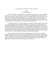
HAltJ'dAR8 PAPGH TM- c;
i,vJ~.:J,~l{
Harley Shanko and Jorgen r'lunck
'fhi s desir:n r es u.lted f'r-o:n t he authors' need for a s i mp Le means
of generatin~ a media for pro~rcrn stora~e and for entcrin~ these
prortrams into their uC system. Eac h had a paper tape reader that
was not yet in use, and a RCA 1802 uP based system. .The dilemna
was t h i s : Isn t t there some simple 'day to punch tape and be able
(4)
HARD'.lAHS PAFl.i:R 'f."PZ LOAD~R. Cel,IT'D
to load it \"Ii thout requiring aof't.war-e to do the ASCII-to-Hl:i:X
conversion and HEX-pair packing into bytes?
Yes! Here is a relatively simple, low cost solution. It
requires only 4k CI·IOS IC' s, exclusive of the input port. Tape
preparation is very simple; _ in the extre~e, only the object code
need be punched, with some leader/trailer at each end. This design
assumes a compatible interface exists at the paper tape reader,_
with +V- Logic 1, OV e Logic 0, for both sprocket and data signals.
MEDIA FORMAT AND FREPAa\'l'ION
It is assumed that a Teletype (TTY) or similar device is available to punch tape and to print hardcopy for a record of the tape
contents. This hardcopy is helpful for verifying accuracy of the
data on the tape, but is not an absolute necessity.
The data to be punched onto the tape is the object code (machine
code) of your program(s). This article deals with hexidecimal
(hex) coding only. Thus each byte will be represented on tape by
two hex characters in ASCII coding. See Table I for a step-by-step
tape generation procedure. This format is useable for both motor
dr~ven and manually-pulled tape readers; the authors have interfaced both types. Since the manual type requires a lit-~le additional 'formatting' for convenience, that format will be described.
By experience it was found to be dif:icult to 'pu~l in' more than
256 bytes per 'pull'. Note that, at 10 characters/inch, that is
about 4 1/3 foot 'stretch'. About one foot of trailer is used to
follow each 256 bytes as a zone to 'stop on'. Otherwise, tape
movement between successive pulls could cause erroneous data entry,
with the 0.1 inch tape hole spacing •. All ASCII control characters
(non-printable codes, column 0 and 1) are transparent to the loader.
Several of these control characters are used advantageously; NUL's
are used for the leader, trailer and between the 256 byte blocks;
CR and LF are used to format the hardcopy. Figure 1 illustrates a
representative listing of a formatted object code tape hardcopy.
\
'l'II~OaY
OF OP8R·\'l'ION
The loadar logic consists of three sections: control, conversion, and input port.
The control section consists of two f:J,.ip-flops and a two-d npu t
OR-r;ate. Figure 2 illustrates the loader th,ine and Figure 3 the
logic. The OR-gate is used to 'detect' the column 3 and 4 ASCIIHEX codes. Full decoding for ASCII-HEX 0 - 9, and A - F codes is
not implemented: and printable ASCII, columns 2 - 7, could be
loaded, but since the object code will only be hex, this fact
permits the simpler decoding. The presence of a valid cod.e and
the leading edge of the sprocket pulse sets F/F 1, removing the
'set' signal from F/F 2. This sir-;nal provides initialization to
F/F 2. F/F 2 di vides ~he sprocket timinr: by tV10: the posi ti ve
transi~tions of F/F 2 Q line sets the DMA flip-flop, F/F 3, TRUE.
F/F 3 Q output then pulls the DNA-IN line. V/hen sensed lJy the
(5)
THGORY OF OPiilAfION CONT'D
uP, an input port Enable is generated (S2 or SCI), resetting the
The register
contents are then present on the data bUs, and the uP writes the
data into memory.
The conversion section consists of a 4-bit full adder and two
4-bit rep;isters. Table II and its note describes the ASCII-to-HEX
conversion. Simply stated, the 4 LSB ASCII code bits are ADJED
to a value of zero or nine, depending on the state of input bit 7.
When hex A - F (ASCII codes 31 - 46) are present will bit 7 be
TRU~; then a value of 9 (binary 1001) is presented to the B-input
of the adder. 'I'he resultant sum is the desired hex code. The
adder outputs are clocked into the first register, and, simultaneously, that register outputs, containing the previous value, is
clocked into the second register. This presents an G-bit code to
the input port.
The input port consists of eight 3-state gates (2/3 of the $OC97
and the output section of_the 4076) and F/F 3, previously described.
In an 1$02 system, F/F 3 Q line connects to the nr:IA-IH line, "\-'1i th
S2 or SCI used for the input port enable signal. If the 1$02
·Interrupt line is not used, SCI can be used; otherwise S2 is re·quired; b of a 4555 dual-decoder can be used to generate all four
State decodes.
mlA flip-flop and enabling the port' 3-state gates.
r·IULTIl-'L~
m:A-IN PCRTS
A contention problem will exist if the tape loader is logicORed with a DMA-IN signal from another input device. The simplest
solution is to add a switch to select which port shall receive the
SCI signal, in order to enable the output of that Dort to the data
bus. Also, wire all ports' ~~ flip-flop RSSETs directly to the
SCI signal. What this provides is a reset to all DNA flip-flops,
whether that port is selected or not. The reason for this is
because on power up one or more JHA flip-flops will come up set,
and will pr-oduce a continuous DI'!A condition on the ORed lJ:'Lt>.-IN
line, until it gets reset. Figure 4 shOl"1S a typical arrangement.
(6)
TABLE I
TAPE PREPArl1TION
Turn on TTY and set to LOCAL mode.
Punch about one foot of leader (press HERE IS key several times).
Punch a CR and·LF.
Now punch the object code. After entering 32 bytes (64 hex
characters), punch CR, LF. Repeat this for each 64 hex character
line. (If tape reader is manually~pulled type, add about one
foot of NUL's after each 256 byte block followed by the CR, LF.
This will occupy about 4 1/3 feet of tape; longer lengths may
be difficult to pull through and load properly.)
5. After end of object code, punch about one foot of trailer ~UL's).
6. If reader is manually-pulled type, and using black tape, a
visual indicator of each block ending is convenient during loadine. This can be added using white typine, correction fluid, such
as 'Liquid Paper'. This simplifies recognizing the trailer gaps
between blocks.
1.
2.
3.
4.
TABLE II
ASCII - HEX CONVEHSION TABLE
cha~~-~~~~-~I~AS~~n~;y~i~l'
~~He~~~T=;;r~;;
·~~;-;;~---·:·:~~tP:~-~1
.
I
----'"8
A
a
1
2
3
4
5
6
7
8
9
A
B
C
D
! 0011
l
1
~
;
lOOll
10100
!i,,;
I
E
F
NOTE:
0000
0001
0010
0011
0100
0101
0110
0111
1000
1001
0001
0010
0011
0100
0101
: 0100
!
I
30
31
32
33
34
35
36
37
38
39
41
42
43
44
l
i~?-
I
I.
I
I
.~_.
-
0000 .0001
0010
0011
0100
0101
0110
0111
1000
1001
0001
0010
0011
0100
0000
Sum ::
-~_~0~31ue ~
0000
1001
I
0101Jl
0110. ~_~~~.
1001
---l
0001
0010
0011
0100
0101
0110
0111
1000
1001
1010
1010
1100
1101
1110
1111
Observe that the hex code for characters a - 9 are
identical to the 4 LSB's of ASCII codes 30 -39:
further note that the hex code for A - F can be
represented by nine (1001) plus the 4 LSB's of 41 - 46.
'rhus, using bit 7 to add zero (for bit 7'" 0) or nine
for bit 7 =1).
( 7)
J
~l--TRA\L(R
.
1?1''{ T£ N
,,-_.......' -......
,
® TIAi Po
®
OW
T~1'E......
_
5PROCKtT
,:
I .
® B\T
®
~
FIt:- 2
I,
0 K 1
~
~,~) ~/~
:3
(9 J-!. P
'PORT
- - --I
I
9
:
1)M~ - IN )
I:.NI\~LE
--------~----------.,;-----!I----.L.-_Yr_----Yr_-----~'r_--II
~tI
II
(SCI OR 51)
-CD
l-lORDWARE:
'PAPER 'APE {...oAUER -
T'M' N 6
~L;
\"j).
VG'. P-.t.A n r ~J:ft
+\1
,.
SaL.. PLtL
')
'-
13
4
12
5
II
l.
10
1
9
{!}
\-
4
>-2.
Ut;'8
In.
'iPRMKhT LI-
3
>-+\1
Q
)----_.
®
--
il
151
®
~WAEL[
I 'Z.
1'2.
.'3
1"3
!
,
14 •
,....,_16
...
.
.-
._-,
I
z.'
z
,
III
CI
-r--=-r
L:=
3
'I
IS
fA
"3
I--
US1
JI
1:J7
-
(
13
r--
tJ5-/
~l
+'1
2.
©
:-
"'"
~
-10
-
12
3
@
B
~'
~1j1!
4049
.I
~
1
14
u
I
i-'
4-\I
3
UCJ5
5
ltDI '3
40n
IQ
'U
~
~
.,
Of ""'2.
~llO
12-
--
J
I..(O'Ce-
t--
I
D
---
---
Ilf
4
I;
':l
I
'Ie
c..
c:
l)' ....
(I
40-' I
S
"")
L/
1<
+-'J
-J:.
BUS
J
.,,~
-3
DA'A
ll"+ r
nl
8
2.
'PI
4.V
L __
-
'3
9
Pi
0
5
,
(J"
i..
"
1'5
I-
3
4
10
\J c"
BOC91
1
\\..\U-'5
ll O O B
~r
,
•
---
5
°1
'-
-'--_Y
14
4
,1\
1
U11
I
/
I
+V
A
, I
/
B
,/0
I
...::>
>
/
II~
5
'l. '\
/
~
\'
C.
~o
1."k.
\"3-
R. ~
y
'2...
®
s c, I
®
\0
"24 ;:IAN, 8.
C)/V/ f..:, - IN
Dr fA
FORTH,
ENAcLr
68Ki:
Df'iR REG.
,DMA
.....
,.
R.eG.IJF~T
D,.. TA 0117
+.
..
~
RESET
I,
1<1-
I
/.
Ig
/8
bl/TA B/JS
'80 C
,
'1
DMA-IN
PORT#2.
DMA
DATA ENA8L.t
At: G, RESl T
DMA Rt.GH:Si
DATA OV.T
#,
ltiki
DMA - IN
SCI
-"
- I'-.,r--/8
LA
/
FIGURS
4
Editor's Notes:
1.
The paper taoe re;:~der mentioned in tIle article is a Model,
TPR-l optical paper tape reader, available assemoled and
tested for U.S. '?32.50 from fiA,SCO, Box 14, l1eadville,
Eass. 02137 USA. Write for more details, or see one of
HAli:CO's ads in most of the hobhyist computer journals.
2.
The TSC-ld02 keyboard oner'ltes in a Jt~ mode for profram
entry. Anyone care to write an 'article showing how they
interfaced this paier- tape reader to a '1'~C-1802?
(10)
IS YOUR
MICROCO~WUTER
S-IOO CO}WATIBLE
Wm. Lee Pfefferman
I'm sure that by now you all are aware that we COSMAC users are
minority members in the world of microcomputing. Being minority members, we are in a sense cut-off from the mainstream of
software that is readily available to the majority. Unfortunately,
many of us are members of still another minority; we operate
microcomputers that are not compatable with the S-lOO bus and
this serves to isolate us from the mainstream of hardware that
is available to the majority.
For me, 5-100 compatibility will make it easier for me to
accomplish the goals that I have set for my computer system and
I am currently in the process of makine my C05MAC-based m~cro
computer compatible with the 8-100 bus. Having an 5-100 compatible computer will enable me to do several things that I
wasn't able to do previously.
1. It will be easy for me to EXPAND on the existing features
of my computer, memory or floppy disk controllers can be
added almost at will.
2. I'll have the ability to CHANGE the existine features of
my computer, in whole or in part. Changing to a different
microprocessor may not be as easy as replacing a single
PC board, but I don't think it will take too much effort.
3. I can INCREASE the CAPABILITIES of my computer by
adding boards that perform a wide variety of functions.
S-lOO boards now exist that will control floppy disks,
synthesize speech, and analyze the operation of a
computer.
.
4. I can IMPROVE on the existing parts of my computer·by
referencing the large amount of literature that has
been written for 5-100 compatible systems.
By changin~ to the S-lOO bus I will also benefit economically.
I will have the ability to select PC boards from many competing
vendors, this will assure me of being ahle to purchase top
quality boards at low prices. In addition, I will be able to
sell and trade my boards with many more people than I could
before. Besides the obvious economic benefits, I hope to use
this capability to keep the structure of my system somewhat
dymamic in nature.
As you can see, in my case, the advantages to having an
8-100 compatible computer are several and I can hardly wait to
look throur,h the advertisements in the next issue of BYTB.
( 11)
LOGIC TSSTER
Tom Jones
I designed this tester from available parts to aid in TTL
trouble-shooting some time before I eot into CMOS. I added the
CD4050 to allow CD1802 design work. It has helped to resolve
some mainframe problems where my Tektronix 453 could not help
me--due mostly to the TRAP or r·1E~·IORY· mode.
To use, set S2 to pulse and connect either pin 1 (for TTL) or
pin 4 (for CMOS) to the test point and observe the 7-segment
display for a "1" or "0" or "P". Also observe the decimal point
for a "pulse, stretched" indication. A square wave will give
a IIp'', but very narrow pulses far apart will only keep the decimal point on. The decimal can now be used to watch for positive
or neF,ative pulses.
If a solid "1" level is observed, you can test for a random
negative pulse for a long period by settin~ the "1!.' on Sl and
setting S2 to "TRAP" mode, and go to lunch. If the solid high
(perhaps 5 volts) ever goes low, the decimal will set. In fact,
if the t~ter is being powered from the supply, the trap will
set even when the probes are not connected if power fails.
If a solid "0" were monitored you could of course check for
positi ve pulses by setting Sl to '!J''' and S2 to "TRAP" as before.
In many computer problems, it is necessary to gate the input
with ano~her function (such as TPB, MRD, or DATA VALID). Connect
input 2 (TTL) or 5 (CMOS) to this function to make sure you are
observine the signal only durinp the period of time you are interested in. Choosing this function can be quite a bit of an art,
and is not limited to data strobes. An' auxiliary flip flop that
is set by one function and reset by another function can provide
this input on 2 or 5, thus allowinp you to choose whatever timing
window your ima~ination can create. I've done it. The other
leg of the gate on IC3 is brought out for TTL but not for CNOS
on mine, I may bring it out for CUDS if I ever need it.
My unit is housed in a small wooden box (a doctor' gave me
several, I have no idea what he receives in them). I wired every
thing on perfboard using a wirin8 pencil and sockets. The transi stor is house numbered, but any good PNP will wor-k, The I/O
jack is half of a 14 pin wire wrap socket, and the plug is the
other half with the pins cut short and carefully rounded with a
file. I simply push the wires in the socket holes and seal them
in with black rubber compound such as the G.~. stuff sold for
sealing car windows. Long leads for inputs and power and very
flexible wire will avoid much frustration in the future.
Some features I would like to add to any unit I build again:
battery power, to avoid using the system power. The system
power may be the problem, and anyway the hook up wires are a
bother, and wi.Ll, ruin the unit if connected backward. I would
like to add a feature that shows an "F" if the input voltage is
not a valid "1" or "0", also. The present unit shows a floated
pin as a "1" due to the pUll-ups. I think some cheap diodes
would make the "e" and "f" ser.;ments both light for a al" level,
instead of only the "e" as presently. I Jeave these to anyone
else interested in his ovm tester, and hope my experiences
using mine will
sug~est
better ideas to you.
( 12)
i
8
c{
-t
I I
1'+ i
I--,-----l
IC~
7
7
ic 3
I If
I
.i
(~ ..n~'" itt:"')
. ,r:)6
o
III
""
_
".5J
----r
/3I ..
7<4
2
f
--1-
,.
I
. /<'3
1~o,
____ .
I-I
:I
II
',,,;-; I
'0
----,..----.'
c: .~ 1
/"3'\
. (a;'0
c0 V
6 ClP -.JJ
/I ,
llf - +5V
7-
_~
-C:"'J
SfG. DI!~pL.A'I: HP 50ra2. -77 50
_~_
.. i
. I
..r
--1-
':
"
/
(13)
.
f 'u;..'
~'l("
...1 I
r:
LETTERS TO THE EDITOR'
Dear Tom:
I am currently wor-ki ng on an interface between the 1802 and a
National Semiconductor's 57109 number oriented processor. If the
hardware result of this could be software coupled to a basic
interpreter such as the tiny basic available from the ITTY BI'l'TY
CmIPUT2;R CO., the result would be a pretty tasty system with the
number crunching done by the peripheral processor. (How does a
21\ interpreter capable of floating point or scientific notation
and functions such as all trig functions and their inverse, square,
square root, log, antilog, LN, exponen,tials? inverse, degrees-toradians, radians-to-degrees, etc. grab you?}
I hope to have some notes available soon if anyone is interested.
If anyone else has any ideas, I'd like to hear from them.
Yours truly, Dave Hayward, 6640 Fielding, Apt. #12, Montreal.
Quebec, Hl~V lN3
Dear Mr. Crawford:
February 6th, 197$.
Received first newsletter last month, keep up the ~ood work!
Just a few comments on my system and the nroblems I have encountered. I am running now an ELF II (no doubt you have heard
of it!) and am running it with 1024 bytes of memory. I put this
together with 2102's bou~ht from S.D. Sales.(it's a good value,
11 to 12 dollars for lK.)
I received ~ayne Bowdish's cross-assembler too, although I
fear it will be a stru~gle gettin~ the ------ to run on our PDP-8/E.
(has anybody done it yet?)
I have done little work with the computer lately but have
succeeded in getting a few of my ideas working; i.e. hexadecimal
counter on the television screen, "t.v. typewriter" - four lines
of eight characters! and a ~emory tester. (sorry but I've no
time to write them up in good)
If would print this request for me as soon as possible? I'd
like to know if anybody has considered a game of Tic-Tac-Toe as
a machine lan~uaF,e project-please send me your ideas.
Has anyoody considered a light-pen for the CDR1861 graphics IC
chip? Please send software that you have implemented.
I have to ~o now so - keep up the good work on the newsletter
and keen well.
Yours truly, D'Arcv rtoberts, 660 Laurier Blvd., Brockville,
Ontario. K6V 5X8 .
Dear Tom:
Jan. 14, 1978.
I am interested in the 1802 User's Group. I just purchased a
RCA VIP, and am very pleased with it. I think it has the potential
of the KIM-l, and am considering starting a VIP NewsLet t er , However, I don't wish to duplic3te your efforts. Do you plan on doing
a re~ular newsletter? Arc Y0U interested in the VIP? (Ed. Note:
I understand RCA is startin~ a VIP User's Group. TC)
Some quick notes on the VIP: Kit assembly went well. RCA
estimates 3 hours for assembly; it took me ~ hours (I'm a fairly
experienced. l<i t bui Lder ) , plus another 4 hour-s of \virinr,: and debuc?in~.
Ny 5 volt power' supo Ly had an interr:li ttent short \"hi ch
reduced the volta~e to about 2 volts; after cutting the plastic
(14)
LETTERS TO THE EDITOR CONT']
sealed assembly open, I discovered a. dd ode Tead dangling next to
the heat sink. I bent it into a safer position, and have had no
further problems.
I'm using the "\'laterloo ll RF modulator (BYTE, Jan '7$), and find
it works well, although it interfers with other channels (even
when not directly connected) if the RF lead is 6 feet long. I
like to lie in bed and play with the VIP, so I needed a long connection to my TV. By putting the modulator near the TV and running
a long video line instead, the interference was eliminated. I
used the VIP's 5 volt supnly to power the modulator.
Documentation provided with the kit is pretty good. The logic
description, trouble-shooting guide, and test programs are excellent; the ROM operating system guide is very good (the operating
system itself isudequate); the CHIP-S interpreter guide is only
fair, however, and there is no description of how each of the 20
video games work.
The video games themselves are pretty good, but don't expect
quality. "Wipe Out ll and llKaleidoscope" are especially fun (I've
only tried three so far). My first project will be the game of
"Life".
.
The CHIP-S interpreter provides a reclhigh level (although hexadecimal) language for controlling the display, reading the hex
keyboard, etc. It is easy to learn, and certainly one of the best
parts of the system. Th~ interpreter itself, by the way, takes
512 bytes of RAM, and the first thing the VIP user must do is enter
the interpreter code (in hex) and save it on tape.
Hardware excansion is easy; adding a parallel I/O port and 2K
more of RM~ is just a matter of plugging in chips •. The parallel
I/O port could use more handshakin~lines, however (there is only
one output handshakin~ line, which is also used on the board for
other things).
In summary, it~s a fine system, and provides lots of room for
both hardware and software experimentation. It's the perfect
system for the computer hobbyist just getting started, or waiting
for "the ultimate svstem ll•
Sincerely, Bob \vallace, Co~ind Design, PO Box 5415, Seattle,
Wa 98105
Dear Tom Crawford:
Thank you for your kindness and for the time you spent to get
me all the information on A.C.~.
I'm really glad to hear, that there is so many of you who work
on 1802 systems1 Here in Vancouver only a few of us have 1802
CPUs - mostly 8080 - Z80 or 6800 the favourite one. We have a
computer club also that hold meetings on the first Wednesday of
every month and also publish a newsletter monthly. In the future
I'm going to send you a copy of our newsletters. On our next club
meeting I'm r,oing to display your letter and I'm sure will have
some very favourahle response about information exchange between
our two clubs.
Please say HELLO to A. C. ~~. members from our Vancouver club!
Thank you again, will be in touch soon1
Sincerelly, Veslot Gellerthegyi, No. 305-1315 Brou~hton St.,
Vancouver, B.C. V6G 2B6
(15)
LETTER TO THE SDITOR CONT'D
Dear Tom:
I read with interest the fact that there is a 1802 club formed
in the Toronto area, from a copy of Byte. I appear to be the only
one in the Halifax, Nova Scotia area using the u-P at least from
the club meeting here that I have attended. I am using a P.E.
COSNAC ELF board with outboard 4K memory. I/O consists of a
ASCII Keyboard, paper tape reader and a model 19 Teletype, of
course.
I have been programming in machine language up until this point
in time as I am not proficient enough in software to prepare an
assembler. \vhile I exuect that you are aware of this already, I
note that Infinite Inc. 1924 Waverley Place, Florida have Tiny
BASIC as well as a few other small programs available. I am
ordering this and if you wish can report on any success that I
have with it. I am enclosing a photocopy of their ava~lable
programs. It appears that only the BASIC related programs are of
much value as the others can be done quite easily by most anyone
who has done anything with the chip.
About the only thing that I have done that might be of some
use to your club might be my pro~ram which is a print using Baudot
TTY subroutine. This will tal(e ASCII data, either immediate from
the keyboard, or a block stored in memory, code conver.t it to
Baudot and serialize it (as a DART would). It outputs on the Q
line and is optoisolated from the selector ma~nets. As it takes
no I/O port or hardware other than an optoisoiator and a few
transistors and resistors, it is a very cheap way to get the 1802
talking especially if you can get an old model 15 or 19 free as I did.
I would be interested in hearin~ from you if you have any software available. I \vould be interested in an assembler and possibly BASIC if the Infinite software doesn't map too well with my
setup. Also I would be interested in any work that is being done
in either 1702 or 270$ EPROMS as I would like to have some form
of monitor and/or paper tape loader in RO!\~ as I am getting tired
of starting from scratch every time 1 shut down to do something
to the Hardware ••••
Thanking you in advance, I remain
Yours very truly, Brian Mi.Ll.Ler-, Box 34 Site 12A, R.R.3
Armda.Le , N. S •
rvlr. Doerwald:
Thank you for acquainting me with your group, I was a bit
surprised at the size 8nd activity of the lS02 ~roup you describe,
1 had thou~ht we were odd birds. I have heard of one group in
Texas. My application fee is enclosed.
1 usually like to contribute what I can to any club I join,
but at the present, I have little to offer. I am only just getting my home-brew 1802 on the air. I started the desi~n a year
ago, but time and money--well, we all know the story. I can send
one proven design, my logic probe, which I have used on CMOS at
home" and TTL at work on the job. (1 am a computer field engineer
representin~ Honeywell Information Systems.)
(16)
LETTBRS TO THE EDITOR CONT'D
What I have is an 11" by 5" perf board half full of wire wrap,
a TTL hex keyboard, and a paper tape read~r.
On the board are
a CPU, 2K of 21L02, a parallel port and a serial port, and an
unfinished UART based cassette interface. (I don't intend to
finish it, but to use the Netronics I/O and their monitor in
RAM.) I have already decoded on the board all the N lines and
32 mapped memory I/O pulses.
On the drawing board still are a CMOS (mostly) TVT, a led 8
digit panel and ASCII keyboard combo, and a simple A/D-D/A port
aimed at a D~I program. First on the list, however is a new
CMOS HEX keyboard utilizing the 74C922 LSI chip and the best
Keypad I can find. My keyboard is a handicap.
Some design thoughts:
.
I suggest that the use of simple I/O driver routines located
in ROM monitors was a shabby attempt by many hardware manufacturers to nail users into thier systems and a practice not~ to be
blindly followed by the users themselves. I believe the 1802
group is still not much influenced by manufacturers. The only
routine I plan to put in RON at preserit is a bootstrap loader
geared for K.C. standard cassette format. (The DART driving Dr~
is too complicated). My tapes will all have a short BRT record
at the beginning which will be a basic loader for the rest of the
tape. This followed by one or the other monitor. (The Basic
Loader will read the starting location of each record on tape and
set the X reg to that.) The only remaining task is the I/O port
assignment, and since each peripheral has an subroutine in the
Monitor, it is easy to give the user a chance to enter each port
in turn and plug them into the routines during startup. This
scheme is not only to help others use my stuff, but to help me--I change my system constantly also. But any 1802 that can boot
in that first record could probably run the program quickly.
J.\Iy other dream is a monitor subroutine that replaces each
jump or call in a program and makes possible dyna~ically relocatable code on an 1802. I lean t.owar-d s the standard 44 pin bus
for system design, but the idea of standards in the experimenter
world is doomed in my opinion, so the best scheme is to be as
general and flexible as can be. The tape format I am designing
is an examo.Le ,
Thank you for your letter, I hope this will introduce me, and
I shall look forward to recievins future issues of IPSO FACTO.
Yours truly, Tom Jones
Dear Sirs:
••• 1 have considerable electronics experience as concerns hardware but am strictly a beginner as concerns software.
I have built a small 1802 basic system as described in Popular
Electronics. It is mounted in a Hammond case and I have been
able to pro~ram it with the help of the above ma~azine. I have
adapted a pro~ram from P.E. to turn the Q LED and a speaker on and
off under control of a pro~ram which I use with Cibachrome colour
processin~.
Even using a CD4047 as a clock, this micro makes a
super tImer (variable Q time intervals).
(17)
LETT~~S
TO THE EDITOR CONT'D
However, I plan to build another for ~eneral purpose usage and
my programming skills will have to be greatly increased.
Looking forward to your newsletters.
Yours very truly, Brian Rusk, 1853 Arizona Ave., Ottawa KiH 6Z5
Dear Tom:
... 1 will soon receive the COSMAC VIP version of the 1802 based
systems and eagerly look forward to a long and hopefully mutually
beneficial relationship with A.C.Z. For the time being, I'll
only have the VIP, a monitor and a cassette machine as I am doing
a product review for QST, the journal of the American Radio Relay
League for whom I \Vor~ ~f.hen that is done, I intend to expand
the memory, somehow wor-k up a full ASCII interface and go from there.
In some respects, I don't share the all too common problem of
tryine to figure out what to do with a microprocessor system--as a
ham I have all too many practical aDplications. Are there other
hams in the club from the Ontario, i.e. generally, "local" area?
If I can be of any amateur radio service to th$m at the ARRL, please
tell them to feel free to call me at any time. My job there is
OSCAa (Orbiting Satellite Carryinf Amateur Radio) Education Program ri:anaser .••
'Thanks for your time and cooperation. I've got a lot to learn
and hopefully, in the near future, I'll have a lot to offer.
Sincerely, Steve Place, 271 Williamsto~m Court, Newington,
CT 06111
Dear Tom:
••• I own a ELF II and am adding 41\ of RAM and the RCA Binary
Arithmetic Subroutines to the Standard Call and Return Techniaue in
a 270$. My next move is to add the Number Cruncher from National
alonF.'; with decoded hex display of upner and lower address bytes.
Some information on parts availability for your readers NSN373
dual 7 se~ment display for the Electronics Experimenters Handhook
1978 - 1802 display is available from Di~i-Key Corp. P.O. Box 677,
Thi~f River Falls MN 56701 for ~2.20 each.
9368 decoder/driver for
the above is available from ACLive Electronic Sales, 44 Faskan
Drive, Unit 25, Rexdale, Ontnrio for a decent price. 86 pin wire
wrap connectors that fit the ~LF II bus are available from Advent
Electronics, 24260 Indoplex Circle, Farmington, }1ichigan 48024.
Their code number is 172-0043-005. They can be soldered to the
existin~ bus and wire wrapped for user's needs.
It is great to hear about other 1802 projects and ideas. That
way I don't work in a vacuum. Thank you. P.S. I would also like
to hear from any other 1$02 users in the Iowa, Missouri, Illinois area.
Yours Sincerely, Alan Bwines, n.I.U. Extension Dept., Fairfield
Lowa, 52556
LETT3RS TO THE EDITOR
CO~~'D
Dear Mr. Crawford:
Following article extracted from Interface Age magazine might be
interesting to our club members.
A byte of music by C.G. Smith in the Nov. issue of Interface Age
teaches how to play music with RCA 1802 Cosmac microcomputer. The
main program \1Titten in machine code for RCA 1802 and 3 J.S.Bach
minuets are included in the article. How it works and how to convert the music tunes to music bytes are discussed in the article.
The main program is 89 bytes long, so if ydu have only the basic
RCA 1802 with 256 bytes RMI, you can already entertain your family
with real music from the micro. How is the interface -- ? --- The
interface required is only a piece of wire. Connect one end of the
wire to the LED attached to the Q output and the other end to the
antenna of the radio, place near an AN and tune the radio. Some
characteristics of the program are:
1. The program works on the RCA 1802 Cosmac microprocessor.
2. Only one memory byte is required to give both note frequency
and duration parameter.
3. The music is started over again if the end of the song is sensed.
4. It is easy to convert real music into music coded form.
5. It is possible to play rest by placing Zeroes in the 'note bits'.
ENJOY YOUR NUSIC AND YOUR ---- l:IICJ.O 11111
Yours very truly, Mrs. Sianhoei Lie
A SINGLE CYCLS CIRCUIT FOR THE 1802
Wm. Lee Pfefferman
Many of you, I'm sure, are aware of the technique of singlemicroprocessor to monitor the execution of a program.
The 1802 has the ability to be single-stepped and a circuit for
single-stepning can be found on P.72 of the COS~~C User Manual.
Unlike many other microprocessors, the 1802 has no minimum clock
frequency. For 1802CD users, like myself, this means that our
COSMACs can operate with clock input frequencies from DC to 3.2 r>IHz.
I have made use of this capability to construct a sin~le cycle
circuit. This circuit facilitates the debugging of both hardware
and software.
The circuit operates by setting a select sWitch to one of two
positions.
1. Setting the select switch in system mode connects the system
clock to the clock input on the 1802. This allows the
COSMAC to operate normally.
2. Setting the select switch to manual mode connects a SPDT
switch to the 1802's clock input. Using this switch to
generate clock pulses allO\'1s the user to inspect all information on the COSI'IAC data and address busses, eg. input and
output data, op-codes, re~ister and memory contents. Please
make sure to note that this scheme assumes that the contents
of the busses can be disolayed without being latched.
steppin~a
A
Sn~GLE
CYCLZ CIRCUIT FOR THE 1802 CONT'D
The circuit that I use is shown below.
r
2k
manual clock
manual
clock
switch
Mode
system: closed
manual: open
r
to
clock
input
470
47
clock
select
switch
system clock
The heart of the circuit is the 2:1 multiplexor, constructed
from the gates labeled #1. The multiplexor is used to pass either
the manual clock or the system clock to the COS~~C's clock.input,
depending on the position of the clock select switch.
I use the S-R flip-flop, gates labeled #2, to de-bounce the
manual clock switch.
Finally, the rest of the gates are used to construct a standard
TTL oscillator circuit.
A FINE RSSOLUTION AUDIO OSCILLATOR PROGRAM
R. G. Edwar-ds
Some people may want to realize a fine resolution for audio tone
generation using a 1 MHz crystal. The following subroutine may be
useful.
Tl,12
TONEGEN
TGI
B4 *
SEP 3
REQ
B4 Tl·12
LDN 9
SR
LSND
LSD
NOP
SEX 9
SR
13ND TG2
SEX 9
Debounce EF4
Return to calline Program via R3
Entry Point for Subroutine
Quit on EF4 Interrupt
R9 is Pointer to Delay Table
LSB to DF
If LSB is a Zero-5 Word Times
If LSB is a One-6 Word Times
(J cycle NOP)
(2 cycle NOP)
BIT 1 to DF
If 8IT 1 is I-Add 2 Word Times
(20)
A FINE
R~SOLUTION
TG2
SMI
BNZ
BQ
SEQ
BR
AUDIO OSCILLATOR PROGRAM CONT'D
01
TG2
TONEGEN
TGI
4 Word Time Delay Loop
Using R2
Set Q and Generate the other Half of
the Squarewave
Notice the routine puts out a symmetrical square wave.
The subroutine produces tones with a full cycle resolution of
16~s with a 1 MHz crystal.
The formulae for the tones are
Delay: 31~50
_ 19
f
e
3B~f~
Example:
Delay constant
for f = 440
Delay
31250
= .440
19
Co
52.022727
~34HEX
Frequency for
delay. 52
f -- 31250
52'f'19 -.. 440 . 140°4
0
Delays for a true tempered scale are:
A
E 4C
7B
F
46
A# 73
6c
B
F# 41
G
3D
C
64
G!:/: 38
C# 5E
D
A
34
57
D# 51
I,
CERTIFYING AUDIO TAPE FOR DIGITAL USE
For best results a tape cassette should be tested before use to
determine if it contains flaws which will create errors. Computer
grade tape is subjected to a series of tests \lhich 'certify' its
freedom from such error producing flaws. Since 'Certified' cassettes sell for two to four times the price of high quality audio
cassettes, you will probably prefer to test the quality audio cassettes yourself. The test to be described is not as thorough as
the computer grade certification procedure but it is more than
adequate for the hobbyist.
The procedure is simply to record a continuous signal on tape
then play back at reduced level and let the cassette interface (With
some additional circuitry) watch for loss of sienal. If the tape
passes the test at reduced play-back level it is almost certain to
be adequate under normal level conditions.
Procedure:
1. Record a continuous 2400 Hz tone at nornal operatin~ level on
the cassette. This can be done by connectine; the tape recorder
to the KansasCity Standard Cassette Interface since the Interface generates a 2400 Hz signal when idle.
(21)
CERTIFYING AUDIO TAPE FOR DIGITAL USZ_.. CQEI' t Q
2.
3.
Reduce the playback signal level to half of the normal level.
Connect the cassette player to the K.C. Standard Cassette Interface and run the tape. If the Data output is connected to the
following circuit, any flaws will cause the LED to illuminate
until reset with the pushbutton switch.
+5V
180A
DATA
PUSH CW TT(11'!
5w,T c rt (NO)
RESET
A COIN TOSS PROGRAM
Robert C. Taubert
I have a COSriiAC SLF II, purchased from. Net.r'onf cs R&D. I have
included a brochure and schematic of the ELF II. I have made no
modifications or additions to my ELF though I have some planned
for the future. I would like to add at least 41\ of memory, an
ASCII keyboard, a monitor, a cassette interface, and some form of
AD-DA board. I would like to be~in running Tiny Basic as soon as
possible with hopes of advanc Lng to l~K or larger in the future.
My first attempt at writing
machine language program Has somewhat frustrating and exciting. I wanted a program that would simulate 15 flips of a coin n.nd display the total number of heads on
the left LED and the tails on the right LED. ~"y next project will
be to add a delay sub-routine to allow me to increase the number
of tails.
I have enclosed a copy of the initial coin toss program, which
I wrote, and the random number generater, which I obtaineJ from
Ross Wirth's newsletter. The pro~ram is simple but does use many
of the 1802's instructions.
a
A COIN TOSS PROGRAI.'; CONT' D
COIN TOSS
00
03
06
07
OA
OD
10
13
16
19
lC
IF
20
23
24
27
29
2C
2D
21"
32
33
36
3$
3B
3D
40
43
45
F$
F$
D3
F$
F$
F$
F$
F$
F$
Fa
Fa
07
51
A3
A4
43
AB
00
5B
44 AC
00 5c
45 . AD
46
00
5D
AE
00
5E
D4
OD
5D
OA
32
OC
FC
01
FA
2F
FC
01
30
OB
33
FC
OD
3A
OB
FE
EC
FI3
IF
FE
FE
F3
5C
5B
EE
64
HEADS
TOSS
"Load R(J).O \'lith address of "MAIN" program
-wLoad R(4).0 with address of "RND" subroutine
""Set P to R (3) • 0
"~lAIN" program counter
~Load address of "HEADS" in R(B).O
Zero "HEADS"
*Load address of "'fAILS" in R(C) .0
Zero "TAILS"
~Load address of "TOSS" in R(D).O
Zero "'ross"
itLoad address of "R~.SULT" in R(Z).O
Zero "RESULT"
itCall subroutine "RNTI"
<4ItIncrement "TOSS"
01
.M(R(A).O) AND 01 to D
~IF D='O
am<) 2F
~ncrement "TAILS"
01
~GO'l'O
33
-.tlncrer:lent "HiADS"
OF
FE
"'''TOSS'' XOR OF
(OF - D.15=Max. # of Flips)
'W'IF D 1= O-COTO IF
~hift "HEADS" 4-Bits left
-tt"HEADS" ;COR "TAILS" & store in lvI(R(E) .0)
5E
-'ltJ)isplay "HZSULTS" & STOP
00
TAILS
RESULTS
REaISTZ;~
ASSlmr:·fENT
R(3)
R(4)
NAIN
RND
Program Counter
Program Counter
R($)
R(9)
RND
RND
Count
R(A)
R(B)
R(C)
R(D)
R(E)
RHD & MAIN
lvlAIN
MAIN
l\'1AIN
NAIN
Seed & Rnd
Heads
Tails
Toss
Result
D""
(23)
11:
1/
A COIN TOSS FROGRM1
~ONT'D
RANDQ1.1 NlWillER GZHERATOR
50
51
54
57
5A
5D
5E
61
63
64
66
69
6c
6E
71
73
75
78
7A
7B
7C
04fEXIT
D3
F8
F8
F8
F8
OA
FA
32
09
7A
7B
7C
00
8E:
73
FB
FA
08
FC
E8
FF
FB
o~~
FE
01
59
58
59
FF
01
F2
30 60
E9
30
A9
AS
AA
F4
50
F)
5A
~Load R(9).0
with address of "COUNT"
R(S).O
with address of "D~"
..c..Load R(A).O with address of "SEED"
"lfZero "COUNT"
""'Get "S~ED"
"AND "SEED" with 8E & store in "D~11
-.tIm '= 0
GOTO 11
"C"COUNT" to D
-cD lOR FF to D
-'C]) AND 01 to D to "COUNT"
1(I)
XOR FF to D
"l(l) + -or to D
~D~ AND D to D, OW XOR D to D
1(GOTCDO
-,cShiftl'TS 6.:i:D" I-Bit left
~"GOUNT" + D to D
"(GO TO "EXIT"
~Load
COUNT
DWo
SEED
MAGNETIC T_'l.F:i: DATA
RECOHDn~G
Ken Smith
Recording di~ital data on magnetic tape or elisc is still (and
always. has been) the most cost effective for mass storage, in both
professional and hobbyist fields. Althou~h a tape recorder is
very common and is conceptually simple, thin5s get involved and
complicated when it comes to instrumentation and di~ital data
recordin~. There are several factors which determine the performance of a magnetic data recording system.
'
1. Data density (bits per inch)
2. Data transfer rate to and from tape
3. Access time to a particular part of the tape
4. Method of recording eg. frequency shift, az, NRZ, Phase encoding,
Kansas City, etc.
5. Data for:nat: preambles, records, inter-record gaps, etc.
6. Coding: this is to combat errors e~. pQrity, checksums, cyclic
codes
7. Error rate.
Most things boil down to one thing; what about errors? This is
the annoyin~-aspect of data recordinfo. There are several thin~s
which cause errors.
1. Tape dropouts due to bad tape
2. Dirty heads
3. Dust
4. Dirty or poor tape transport system
5. A cassette which binds and jams or callses too much friction.
The first solution is obvious, use your exnensive stereo reel-toreel deck. But almost all people use an inexpensive cassette
recorder. Use ~ood tape to be~in with. Cheap bar~ain tapes are
temptin~ but are unpredictable for dropouts, etc.
Maxell UDAL c-60
is one of the best for computer applications. Sony is also ,good.
(24)
MAGN~TIC
DATA RECORDING COfIT'D
TAP~
Don't forget that in a cassette, half of the transport is the
cassette itself. A bad cassette will make a squealing noise when
rewindin~.
As for the cassette recorder itself, make sure it does
not 'chew-up" the tape. Look at the tape \thi ch has been played a
few times. A bad recorder will put longitudinal lines, scratches
on the tape or fray the edges.
Clean the heads, guides, capstan and pinch roller with alcohol.
Record a tone and play it back. Does it sound "sick" or "watery"?
Dees the recorder have hum or noise from the motor at the output?
There are several reasons why -a recorder (a cheap one) 'won" t
record or load programs.
SATURATION RECORDING
Almost all commercial digital tape units use "saturation recording". This method saturates the tape material in one direction
or the other, which is what binary data is; one state or the other.
Recording this way is very sim~le to do. The record head current
is switched from one polarity to the other. The current must be
sufficient to saturate the tape, typically 1 to 5 mAe Since we
want to switch the magnetic flux, a current source (not voltage) is
desired. The head is usually fairly inductive which impedes a
change in current. Fig. 1 shows a simple circuit for saturation
recording. Saturation recording considerably reduces dropouts on
playback and hence errors. The value of C and R will depend on
head resistance and inductance. Adjust R for minimum current for
good saturation, C for best current transient response. Sl is
always in the recorder for switchine between record and playback.
Disconnect the record amp.
+sV
c
TTL.
Sca r c e
~SO-11-
..L-,J 111
I-Ih
.
<J~(---Li'.v/~.
,aafF
R
To
FIG. 1
c
R~(Qr,J jP/tlj't{iC"k
Head
fJ~'r'BIiCfC··
II /"1~~
PHASe.; ENCODING
Phase encoding, a favourite of mine, is commonly used commercially.
This is a method by which data is recorded on tape, while Kansas
City is another way. Fig. 2 shows how phase encoding works. The
direction of chanze in the middle of the bit "cell" determines if
the bit is 0 or 1: Phase encoding has many advanta~es. Like Kans~
City, it can be A.C. coupled (no D.C.). On playback, the zerocrossines are detected, like Kansas City. But for a given maximum
frequency resnonse of the recorder, phase encoding gives 4 times
the data rate that Kansas City will. 1200 baud phase encoding •
requires a frequency response only from 600-2400 Hz. 300 baud
Kansas City requires 1200-2400 Hz.
(25)
MAGNETIC TAPE DATA
R~CORDING
CONT'D
In addition phase encodin~ is self-clockinG; the code itself
generates the data and the clock. It is also fairly insensitive
to tape speed variations since the clock is regenerated by the
code. Also, no start or stop bits are required. This is also
true for Kansas City but not-FSK.
o
o
o
o
c
o
JlJUl
FIG. 2
Phase encodine is simply ~enerated by exclusive-oring a symmetrical clock, at the baud rate, with direct data synchronous
with the clock. Since Dhase encoding is simple to ~enerate and
recover (data and clock~ simple software will replace the need
for a DART.
Phase encodin~ has its problems. A cheap recorder with bad
equalization may not properly reproduce phase encoding. We only
worry about the zero-crossings. Also if the playback signal is
inverted, the data gets inverted. You must determine if this
happens with your recorder.
A SIMPLE 25 IC - 2 TRANSISTOR CODS
PRACTIS~ OSCILLATOR
Doug, Nancy Inkster and ,Doug Olenick
With this short program and a minimum amount of hardware additions, you can turn your micro into the most expensive code
practise oscillator you ever saw.
The oscillator can be "keyed" by the "i" button but for true
code practise, hook a code key from gnd. to the EF4 line on the
edre card.
"The freq. can be changed to anyone of 256 values, (09 is a
good start), by changing the # in memory location 01.
00
01
02
03
04
05
06
07
08
09
OA
OB
OC
OD
0"~
OF
10
F8
Frea.(09)
.4.7
27
87
3A
03
39
OC
7A
,30
00
3F
OC
7B
30
00
.,. 5 1/
Q LINi£
lOOA
CeDE
Kr: r
£F.,.
(26)
LINe.
HEX~DECIMA1
CONVERSION, AND ASCII
Ken Smith
Table 1 is very convenient for hex-decimal conversion. A calculator is not needed. A full address or register is 16 bits or
4 hex digits. The largest hex number is FFFF or 65535 decimal.
The 4 HEX=DEC columns in the table corresponds to 4 hex digits
in the hex number.
Let a hex number be represented by X4X,X2Xl. To convert to
decimal, multiply each di~it by its weighting factor (4 096, 256, 16
and 1 respectively) and add the products. Table 1 has already
multiplied each digit by the weightin~ factors. eg. convert C8F3
to decimal - look up each individual hex di~it in the table (in
each column) and add the 4 decimal equivalents thus,
C8F3 hex 49152 + 2048 't' 240 + 3
-51443 decimal
To convert decimal to hex (more often done but more difficult) is
the reverse procedure. The decimal number N is broken up such that
N -4096 X~+256 X3+16 X2+-Xl. Starting with the first hex digit
(left), f1nd the decimal number (and corresponding hex) less than
or equal to the decimal number N. Subtract the two, giving a remainder. Do the same, usin~ the previous remainder, for all 4 hex
digits. eg. convert 40,500 to hex - The largest number less than
or equal to 40,500 in the first column is 36864 (or 9000 hex),
subtract to get 3636 and so on. Thus,
40,500 = 36864 + 358l~'" 48 ...4
• 9E3l~ hex
Table 2 shows the ASCII code, a universal code used in the
computer industry. A full ASCII code has 8 bits (a byte), 7 data
bits and 1 parity (usually even). The parity bit is the most significant (left) bit. Table 2 shows ASCII without parity. Hence
the maximum code is 0111 1111 or 7F hex. Full ASCII has upper and
lower case letters and 32 "control characters" which are usually
non-printing. The most important control character is carriage
return (OD hex). Many terminals don't have Lower' case letters; a
partial ASCII code. Normal up?er-case letters, special characters
and a few control characters; at most 64 characters. ASCII code
for this is only 6 bits; In fact the PDP-S text editor "packs" 2
characters into its 12 bit me~ory locations. The actual form of
many special characters varies from terminal to terminal. (I've
seen some mighty strange character generator ROMS-you can get ones
with various foreign alphabets.)
1IO
TRIVIA
The 1802 has one unusual or illegal opcode; "b8". The manual
does not say what it does, but here is what it does: "68" is
actually an input instruction to port 0 (lNPO). The only problem
is that during input N2,Nl,NO =0 (since it is port 0) thus the
input port lo~ic is not activated. If none of N2,Nl,NO are high,
we can't tell if an I/O instruction is bein~ executed unless "68"
is decoded from the data bus during a fetch cycle (50). A "68"
inputs data to M(R(X)) (as usual), but puts 68 into D, instead of
data into D!
( 27)
Hexadecl~al
-rsx::'P I'Ui 1 Y
0QI')()
0001
Q010
0011
0100
0101
0110
0111
1000
0
1
2
1
-'
4
5
6
7
'3
9
A
F
C
0
E
't;"
0
0
0
256
512
763
1024
1230
1536
1792
2048
2304
2560
2316
3072
3323
3594
3 940
1
2
3
4
5
6
7
8
9
16
32
43
64
30
96
112
128
144
160
176
192
209
224
0
1
2
o
1
2
3
4
5
6
409(,
9192
12238
1639 4
20490
2 4576
23672
32763
36864
40960
45056
49152
53249
0
1
2
3
4
5
6
7
3
tOOL
9
A
E
C
D
9
9
A
E
C
D
573Ld~
~
F (,1L1.40
F
~
ASCII
..
2
H~{
o
?
J
4
0 'rJL S8H ST{ ~'I',{ -~f)T
1 DL~ DCl T)C2 JC31T)~4
2 SP !
#
$
"
1
2
3
It
3 a
,.,
p
4 @
D
A
c;
P
T
:=i
S
~
-'
6 ,
b
d
a
c
r
t
q
s
7 0
'oJ
5
(~ltho~t
~
7
A
F
C
D
2
F'
9
!t'r
111~
escaOA
E
F
,.,
?
.....
D
--"
LF
VT
::<'F
FS
G:=i
SO
SI
G.3
=1S
iJ3
=
>
•
/
'~
0
t
'1
-
&
,
(
)
6
'3
.,
<.
:.{
9
I
*r
+
7
J
K
L
X
h
x
Y
Z
[
\
fiT
]
1
y
j
1{
I
11
z
{
I
}
3
J
e
u
':0'
V
f
v
,~
\.Z
(.[
S
w
~~~", ,
!
...
A
%
5
S"JE 2:.3C
,
,
-
,....
F
?
')
nsr
......
Char~cters
~atn
'1
D
oJ.
~L;;
\
,.,
v
E3
Shlft aut
'3~1 f t
A
p
Ck~
50
'31
VI
9
31'''::
£1'3
:JS
HI'
LF
7
8
9
10
11
12
13
14
15
~';;L
Carrt~~e retur~
AC'{
F2L
P5
0
AC:(
~1
I-<~\q
6
7
8
SY~J
F:;'
~Tr
1
-'
4
5
240
'3
DC 1..
2TX:
a
1
2
3
4
5,
Parity)
~~ll (lea~~r O~ paoer taoe)
start of h~a11'1,!
'3tart of text
~~d ,')f text
~n1 of tra1s~tsslon
-::'11'11 ry
Ac1mowled c;ellent
3ell or atte'1tlon sl~'1al
'Packsnace
;.{orl zontal t.abr'L atl on
Ll'1e feed
'lertlcal ta~~latlo'1
':o'or., feed
\I'JL
= :r~~,-:
~ A~\.
~\T'~
Contr')l
son:
srx
:o~verslon
:E{=D~C
:-r~X=D~~
1010
1011
1100
1101
1110
111..1
1
DAcl~al
H~=D'~C
T:.. 8L:"; 2
0
-
DC2
DC3
DC4
~AX
SY01
~TP.
CN'J
SJB
3·3C
?3
GS
5?
J2:L
co~trol 1
Devlce co~trol 2
Devlce contr~l 3
'Jevl c e control 4
'J~~atlve ack
Synchronous/Idle
~ni of tra~s~ltte1 block
Cancel (error 1'1 1ata)
T~n;l of !ledl·.l~
3tart of soeclal se1u~nce
-::;scaoe
Flle se:)aratar
}ro'.lO seoarator
qecord seoarator
LJnlt se-parator
',oace
~evlce
Delt~te
I TEr:S FOR SALE
1. An assembled ~LF-II (Netronics :tg;D Ltd) with power transformer,
RCA 1802 User's ~anual, RF Modulator and numerous programs
from POPULAR iL~CTROKICS and IPSO F~CTO. Selline price is
US·,llO.OO. Please contact: Peter U. Snyder, 1417 g 53rd St.,
Chicago, Illinois, USA 60615. Phone (312) 241-7236 after
6 PM ~ST.
2. TE C-1802 (slow chip), with TEK.TRON 5V Ill. DC regulated power
supply and TEC-1802 5 slot mother board. All assembled and
',-,i th documentation. Contact ~·lr. r'i. Skodny, 80 Weir St. S.,
Hamilton, Ontario, CANADA L8K 3A6.
3. For Sale:
16 pin ~.W. gold sockets
-.) .65
14 pin W.W. gold sockets
.60
16 oin tin plated solder tail sockets .30
14 pin tin plated solder tail sockets .25
50 «:«, Vector pins
2.25
Contact: Bernie Murphy, 102 McCraney St., Oakville, Ontario,
CANADA L6H IH6
4. For Trade:
I have 1 Memorex 1240 ASCII terminal; 60, 30, 15, 10 c.p.s.,
120 print positions, upper/lower case, paper carrier. Al condition. Cost ·~5, 500 new. All servi ce manuals included.
I will trade for a 2 channel oscilloscooe, 15 hHz or better. I
prefer a solid state 'scope, although a good quali ty TEI~TRCNIX
or HP tube 'scope will be considered. Serious offers only
please. Contact: Bernie Murphy, 102 McCrany St., Oakville,
Ontario, CANADA L6H IH6.
A DIS-ASSEMBLY OF ED MCCORMICK'S r.mNITOR
Robert Edwards
(Ed. Note: Ed McCormick's Monitor consists of a hex keyboard monitor and cassette interface, in 255 bytes of code which can be
stored in a PROt1(1702) and located in any memory page. It is desi ~ned to wor-k with a 2 r,IHz clock, and lK bytes of R.l\!',:! located at
0400 to 07FF. This monitor was ori~inally published in POPULAR
ELECTRONICS and DR. DOB3'S JOU~NAL, with accompanying test, in
the followin~ form:
Loc
----------------------- Contents ---------------------------C D E
0
1
2
6
8
A
F
B
7
9
3
4
5
00 Fa 07 Bl F8 FE Al El 6c 64 FC FD 33 3B 3F OD 37
10 OF 6c 64 21 BF 3F 15 37 17 6c 64 21 21 AF FO EF
20 3F 20 37 22 32 34 F6 33 2B 7B 6c 64 3F 2C 37 2E
30 31 2A 30 2B DF 00 00 00 00 00 00 3A 3E 7B F8 04
40 Bl F8 00 Al B2 B3 B4 B5 B6 B7 39 9E FB 80 A7 F8
50 08 A5 7B F8 00 51 35 56 3D 58 F8 00 FC 01 35 5C
60 FC ED 3B 56 F8 B3 A2 7A 82 -FF 01 C4 3A 69 35 6E
70 . 3D 70 F8 00 FC 01 35 74 FC ED 3B 85 7A FO F6 51
80 F8 59 A2 30 8F 7B FO F6 51 87 F4 51 FS 6$ A2 $5
90 FF 01 A5 3A 68 64 91 FF 08 3A 4F 7A 00 00 7A F$
AO 00 A6 A7 F8 10 A2 F8 01 A3 30 AB 31 BO 73 30 B3
BO 7A 30 B3 83 FF 01 3A B4 82 FF 01 A2 32 C$ F8 07
CO FF 01 3A CO 30 c6 30 AB 86 3A D7 3F A3 F$ 01 Ab
DO FO A4 Fa 09 A5 30 E5 87 3A F4 85 FF 01 A5 32 ED
EO 84 76 A4 33 A3 F8 08 A2 F8 OE A3 30 AB F8 01 A7
FO F8 20 30 A5 FS 00 A7 64 91 FF 08 32 9E 30 DO 00
I leave it up to you, the reader, to decide which form of software documentation you prefer: the hex dump above, or the commented
assembly language below.)
(30)
EDWAHD
!,i~CCOmIICS'
Fa
START
00
02
03
05
06
07
0$
09
OB
OD
OF
11
12
13
14
15
17
19
lA
IB
lC
ID
IE
IF
20
22
24
26
27
29
2A
2B
2C
2E
30
32
34
07
Bl
F$ FE
Al
El
S ELF OPERATING SYSTSM (2 MHZ CLOCK)
(0400 TO 07FF)
6c
64
FC FD
33 3B
3F OD
37 OF
6c
64
21
BF
3F15
37 17
6c
64
21
21
AF
FO
EF
3F 20
37 22
32 34
F6
33 2B
7B
6c
64
3F 2C
37
ALTLOOP
DISLOOP
2E
31 2A
30 2B
DF
EXEC
LDI
PHI
LDI
PLO
SEX
INP
OUT
ADI
BD
BN4
B4
IUP
OUT
DEC
PHI
BN4
B4
INP
OUT
DEC
DEC
PLO
LDX
SEX
CASSETTE IHTERFACE FOR lK HEji';ORY
Robert Edwards
07
1
FE
1
07FE .. Rl; 07FE::: ADD~ESS OF fUNCTION
07FF ~ ADDRESS OF HIGH & LOW BYTES OF ADDR~SS PUT IN
THROUGH SnITCH~S
1
I-.X
GET SVHTCHES (FUNCTION R;~QUESTED)
PUT SWITCHSS ON DISPLAY
D OVERFLOWS IF SWITCHES ~ 2
IF SWITCHES,. 2 GO TO CASSETTE 10
WAIT FOR TOGr.LE
~AIT UNTIL TOGnLE GOES OFF
GET SWITCH~S (HIGH BYTE OF ADDRESS)
PUT HIGH BYTE ON DISPLAY
MOVS Rl(X) BACK TO 07FF
PUT HIGH BYTE OF ADDRESS IN RF.l
WAIT FOR TOGGLE
WAIT UN'l'ILTOGGLE GOES OFF
GET SWITCHES (LOU BYTE OF ADDRESS)
PUT LO~v BYTE ON DISPLAY
MOVE Rl(X) BACK TO 07FF
MOVE Rl(X) BACK TO 07FE
PUT Lmf BYTE OF ADDRESS IN RF.O
REQUESTED FUNCTION ~ D
4
4
FD
CASIO
11,J{
4
4
1
F
II
'tit
4
4
1
1
F
F
BN4
~.
B4
BZ
SHR
BD
SEQ
INP
OUT
~
BN4
B4
y-
BQ
BR
SEP
&
EXEC
DISLOOP
4
4
~
ALTLOOP
DISLOOP
F
F
~X
WAIT FOR TOGnLE
WAIT UNTIL TOGGLE GOES OFF
SWITCHES~O ~ START EXECUTION AT USERS ADDRESS
tow BIT OF D INTO DF
SWITCHES~1 • DISPLAY 1·1E1'·TORY AT USERS ADDRESS
LIGHT LED TO SIGNAL ALTERIEG Fa..:ORY
GET SVH TC HES
NET.v DATA FOR THIS !:IEMORY LOC TO DISPLAY [Rl(X) -= Rl(X)+l]
WAIT FOR TOGGLE
WAIT UNTIL TOG~LE GOES OFF
ALTER MEMORY AT SUCCEEDING Rl(X)
DISPLAY MSfllORY AT N£XT SUi~CEEDING Rl (X)
START USERS PROGRAM 1I.TJTH P = F
-
3B
3D
3E
40
41
43
44
45
h6
47
h8
49
4A
4C
4E
4F
51
52
53
55
56
58
5A
5C
5E
60
62
64
66
67
68
69
6B
6c
3A 3E
7B
CASIO
Fe 04
Bl
F8 00
Al
B2
B3
B4
B5
B6
B7
39 9E
F8 80
READCAS
.'1.7
Fe
A5
7B
F8
51
35
30
F8
FC
35
FC
3B
F8
A2
7A
82
FF
C4
3A
08
RCSTART
00
56
58
00
01
5C
ED
56
B3
Im1LOOP
BNZ ¥+3
SEQ
LDI 04
PHI 1
LDI 00
PLO 1
PHI 2
PHI 3
PHI 4
PHI
5
PHI 6
PHI 7
BNQ ~'mITECAS
LDI 80
PLO 7
LDI 0$
PLO 5
SEQ
LOI 00
STN 1
B2
BN2 ·of
LDI 00
ADI 01
~ -2
B2
ADI ED
BND I Bf-1LOOP
LOI B3
PLO 2
RE(~
01
snr
2
01
69
NOP
BNZ
..-}
BITLOOP
GLO
SET Q TO BR:i.NCH TO CASSErrr~ 'JHITZ AFTEH INITIALIZATIon
0400 ~ Rl
CLEAR HIGH BYTE OF R2 THROUGH R7
PUT HIGH ORDER BIT IN R7 (SET 2:IW OF BYTE S';JITCII TRUS)
-
PUT SHIFf COUNT IN RS
TunN OF Q
CLEAR 8YT~ TO
B~
N
M
LOADZO
LOOP ON I'lARKS IN TA Pr<: RECORDE;{ OF Bj£T\v'E~N BYTZS
ST~\RT 208. 3333~s HAL~ CYCLE r'lEASURE (EQUALS 52 4.,M.s CYCLE: T1;:::': S)
ADO ONE TO D EVI~H y J.6~s (EVE~LY 4 CYCL~ rn.as)
EXITS '.lITH D ~CJUALS 12 AT I·iOST
\'lAS EF2 HIGH ron 22~ (56 ~ CYCLE TUIES) (13+ED OVERFLO~lS D)
I~1ARK
IF SPAC~ STAR'r 5 MILLISECJPO DSLAY
DELAY ACCORDING TO DSLAY CONSTAIJT IN R2.0
R2.0
83 (179) FC·l"{ 5 EILLIS~GCI<DS; 68 (104)
59 (89) FOR 2.5 r-IILLISl<.;CONDS
LOOP IS 7 4,.s CYCL~ rrnss
179 x 28
5012 ~s; 104 x 28
2912~
89 X 28
2492~
=
=
=
=
ron
2.9 j·:S
35 68
3D 70
F8 00
Fe 01
35 74
FC ED
3B 85
7A
FO
F6
51
F8 59
A2
30 8F
7B
FO
F6
51
87
F4
51
F8 68
A2
85
FF 01
A5
3A 68
64
91
FF 08
3A 4F
7A
00
00
7A
F8 00
A6
A7
F8 10
A2
B2
BN2
LDI
ADI
B2
ADI
BND
GOTSPACE REQ
LOX
SR
STN
LDI
PLQ
BR
GOTIiARK SEQ
LOX
SR
STN
GLO
ADX
STN
LDI
PLO
NEXTBIT GLO
SMI
PLO
BNZ
OUT
GHI
*'
WfI/
00
01
tf
-2
ED
GOTrv1ARK
1
59H
~ 20~s)
GOT A SPACE - TURN Q OFF
GET PARTIAL BYTE
SHIFT IN A ZERO FROM TOP
-PUT BACK PARTIAL BYTE
SET DELAY FOR 2.5 MILLISECONDS
2
NEXTBIT
.1
7
1
68
2
5
01
5
BITLOOP
4
1
S~lI
08
BNZ RCSTART
REQ
IDLE
WRITECAS REQ
LDI
PLO
PLO
r.1ARKGEN LDI
PLO
DETERMINE IF A NARK OR
SPACE AT SAMPLING TIME
WAIT FOR EF2 TO GO HIGH THEN
ADO 1 TO D FOR EVERY 4 CYCLE THIES (16 s )
LOOP BACK IF EF2 STILL HIGH
D OVERFLO\'JS IF D~12 (12' 4+ 4 X 12;; 52 C.T.
00
6
7
10
2
GOT A MARK - TURN Q:CN
GET PARTIAL BYTE
SHIFT IT RIGHT ONE BIT
STORE IT
GET CONSTANT 80 OUT OF R7.0
ADD IT TO PARTIAL BYTE
STORE IT
SET DELAY FOR 2.9 ~rrLLISECONDS
-
GO BACK TO BITLOOP UNTIL 8 BITS HAVE
BEEN PROCESSED
DISPLA Y BYTE
07FF IS LAST BYTE TO BE LOADED
IF ALL OF CORE LOADED - TURN_OF Q AND IDLE
TURN Q OFF
SET R6 - LEADER SWITCH
CLEAR R7 - END OF BLOCK SWITCH
GENERATE A MARK - 8 CYCLES AT 2400 HZ
208.333~s HALF CYCLE (52 ~s CYCLE
TI~ffiS)
A6
A8
A9
AB
AD
AE
BO
Bl
B3
B4
B6
B8
B9
DB
BC
BE
CO
C2
C4
C6
C8
C9
CB
CD
CIt'
DO
Dl
D2
D4
D5
D7
D8
DA
DB
DD
DE
EO
El
E2
E3
E5
F8
A3
30
31
7B
30
7A
30
83
FF
3A
82
FF
A2
32
F8
FF
3A
30
30
86
3A
3F
F8
A6
FO
A4
F8
A5
30
87
3A
85
FF
AS
01
AB
BO
B3
B3
QTEST
RESETQ
VARDELAY
01
B4
01
C8
07 FIIDELAY
01
CO
c6
AB
LEADTEST
D7
A3
01
BYTEOUT
09
E5
EBTEST
F4
01
32 ED
84
76
A4
33 A3
F8 08
SPACEGEN
LDI
PLO
BR
BQ
SEQ
BR
REQ
BR
GLO
SMI
BNZ
GLO
SMI
PLO
BZ
LDI
S1>1I
BNZ
BR
BR
GLO
BNZ
BN4
LDI
PLO
LDX
PLO
LDI
PLO
BR
GLO
BNZ
GLO
SMI
PLO
BZ
GLO
SHRC
PLO
BD
LDI
01
3
.,c' +2
RESETQ
VARDELAY
IW
54 ',vORD TIMES TO HERE FROI·) EITHER SEQ or REQ FOR MARK
106 TO HERE FOR SPACE
54 X 4
216 (SHOULD BE 208.3333); 106X4 424(SHOULD BE
=
+1
=
i CYCLE TO HERE
3
01
6 WORD TIMES IN
~-2
10 TO HERE FOR MARK - 62 FOR SPACE
DECREMENT CYCLE COUNTER
2
01
2
LEAD TEST
07
01
18 TO HERE FOR MARK - 70 FOR SPACE
FIXED •• DELAY OF 28 CYCLE TIMES IN LOOP (SHOULD BE LDI 05)
(26 CYCLE TINES)
....+2
2 CYCLE DELAY (SHOULD BE 2 NOPS)
52 TO HERE FOR MARK - 104 FOR SPACE
LEADER SWITCH IS ZERO ~rnEN
LEADER IS BEING GENERATED
IF NO TOGGLE - CONTINUE ~~RK GENERATION
CLEAR R6 - LEADER FLAG
_-2
QTEST
6
EBTEST
MARKGEN
01
6
4
09
5
SPACEGEN
7
ENDBYTE
5
01
5
DOUBMARK
4
4
l'1ARKGEN
08
PUT BYTE TO BE OUTPUT IN R4.0
PUT SHIFT COUNT IN R5.0
GENERATE SPACE THAT PRECEEDS DATA
BRANCH AFTER DOUBLE MARKS AT END OF BYTE
REDUCE SHIFT COUNT - BRANCH IF ALL
8 BITS OUTPUT
GO TO MARK OR SPAC~ ACCORDING TO
BIT OF BYTE
GENERATE A SPACE - 4 CYCLES AT 1200 HZ
416~667)·
A2
Fe
A3
30
Fe
A7
Fe
30
Fe
A7
64
91
FF
32
30
PLO
LDI
PLO
BR
AB
01 DOUEr·1ARK LDI
PLO
LDI
20
BR
A5
00 ZNDBYTE LDI
PLO
OUT
GHI
SMI
oe
BZ
9E
BR
DO
OE
2
OE
3
QTEST
01
7
20
Y1ARKGEN.2
00
,..,
t
4
1
oe
WRITECAS
BYTEOUT
VARIABLE DELAY FOR SPACE - 56 CYCLE TIMES VS 4 FOR HARK
(THIS SHOULD BE LDI OD??)
AT END OF BYTE - SET EOB SWITCH
AND GENERATE DOUBLE MARK
AFTER DOUBLE MARK AT END OF BYTE RESET END OF BYTE SWITCH - DISPLAY
BYTE
ALL OF CORE WRITTEN AFTER 07FF
GENERATE TRAILER OF ~~RKS
DO ANOTHER BYTE
NOTE OF CAUTION ON USING MY PROGRAMS FOR CASSETTE INTERFACE WITH CLOCK RATES LESS THAN
2 MHZ
Edw. M. McCormick
The l:C standard interface described in Feb. '78 Popular Electronics and No. 19 of Dr. Dobbs
urnal was designed for a 2 mhz crystal. Although the programs will operate at lower clock freencies, they will not produce the KC standard tones. If a 1.78 mhz crystal is used the tones
11 be 1030 hz and 2060 hz. A 1 mhz clock means that these tones are 597 hz and 1158 hz. Hower, the cassette read and write proerams should operate correctly at these lower frequencies.
will simply take longer to read and write the records. The only problem will be in exchanging
pes between systems.
Reexamination of these proerams (written a year ago) indicates that it is not possible to
dify them to get 1200 hz and 2400 hz tones if the clock is less than 2 mhz.~he basic reason
r this is in the cassette write program. The minimum number of steps that are used for each
If cycle (in order to make all the necessary Checks) is 27 instruction executions. This takes
6 microseconds with a 2 mhz crystal. Thus a half cycle on Q can not be less than this time
ich means that 2315 hz is the highest tone which can be generated with that crystal. To obtain
~her frequencies for lower clock rates would require a complete rewrite of the programs.
It
not be done by chaneing any of the values in the proerams (including the operating system on
gej4 of DDJ).
Either use a 2 mhz crystal or live with the non-standard tones when using lower frequency
n
-ys taLs ,
Sorry about thatl
~
-
C""\
THE
1802 MUSIC
MACHINE
by Cee will1l\ll18
It is well known by most ex~erimenter8, that music ia made up
of different frequenoies and durations, plus pauses (or rests),of
dif!erent durations. It is a1ao known that a microprocessor is'
eminently oapab1e of deriving suoh frequencies, and outputting
them from a soris1 output port. In the oase of the C01802 mioroprocessor, by R.C.A., as used in the Cosmac Elf, the Q-output
port oan be programmed to playa melody, via any suitable amplifier and loudspeaker, or even 10 - 20" of wireS
Duration Bits:
For the duration of a note, music works in a binary
fashion. Some bB9~0 cammon notes are quarter notes, eif~th notes,
sixteenth notes,~to., known a~ crotohets, quavers and semiquavers,
respeotive1y. They sometimes have a dot placed afte~ them, which
increases their duration by 5~. Suoh an increase can easily be
ooded in a binary system. Some examples are shown in Table 2.
Music Code
J
J
J:
Several musio programs were studi~d, ino1uding those 1n the
Nov.1977 Interface Age, and in the Feb.1978 Popular E1eotronics.
While they worked well, within their limitations, it was decided
to make a program with some features that would be more flexible.
This would enable even a neophyte musioian the knowledge to program in his own melodies. Some useful features of the program are:
Duration
Duration Bits
1/16-note
o0 1
l/8-note
010
:3/16-note
0 1 1
1/4-note
100
J/8-note
110
1. Only one memory byte 1s needed to generate the note frequenoy,
its duration, and Whether it 1s in a low or h1gh octave.
J
J.
2. By sensing the end of a melody, it oan b8 repeated over.
7
1/8-rest
010
t
1/4-rest
1 0 0
3.
A range of two ootaves, with sharps and flats (the b1aok
notes of a piano), may be programmed.
4. Onoe the program has a melody entered at the basio speed, a
simple ohange oan alter the speed to anyone of fOUr other
speeds.
5. As music itself is based on a oode system of seven letters,
A to G, (the white notes on a piano), six of these seven
notes, A to F, are coded with the same HlX-code letters.
ps or flats), use HEXNote G, and the five aocidenta1s
code numbers. A pause, or rest, llshar
s always ooded as a zero.
THE MUSIC BYTE
Eaoh data byte that is used to program a melody, has its 8
data bits broken up into J parts as shown in Figare 1. The 4 low
bits define the note frequency, the next :3 bits define the duration! while the high bit defines whioh ootave is ohosen. The
ren tant data byte is oalled a Irtusio Byte.
Ootave Dit:
The program has one basio low ootave of twelve scmitones programmed into it. This ootave includes the seven basio
notes labelled A to G, plus the five sharps or flats. To derive
the high octave of notes, the program doubles the pitch of these
low notes. This is triggered by programming a 'I' in the octave
bit. Sane e%8!llp1es show haw the music byte is bulltup, and then
oonverted to HEX-code:
=1:9
0 1 1 = 2B
0 0 0 = 40
1. Note G, J/8-note 10ng,high ootave:
1 1 1 0 1 0 0 1
2. Note B, l/8-note long, low ootave:
0 0 1 0 1
3. A rest, of duration 1/4-note:
o1 0 0 0
THEORY OF OPERATION
The program shown in Table 4 is wa1ked-throup:h in 30me detail
below. This has been done, to help neophyte progr&~ers like myself and others, to be better able to grasr the use of some of the
simple, and extrame1y useful 1804-program code instructions. To
aid in these explanations, an arbitrary first ~usio Byte of B9,
(a high octave G, J/16-note long) has been placed in eddress 50,
the address of the first note of a melody. The 1802-register 10oations are varioua1y referenoed as R-1.0, low-C, hiEh-B,Registerr, etc.
r~
ootave
bit
Table 2
lduration: note bits I
: bits :
:
Figure 1
Note B1t§:
Whether the note to be ooded 1s in the high or the low
ootave, the 4 note bits are always ooded in HEX-oode as the lower
HEX-digit, shown in Table 1.
i T! I ! I
AI cI rI
rI rest
Ilusio Code: A B C 0 E r
G
Low Hex
A B C D I:
r 9 4 5 6 7 8 0
digit
Where a , 1s a sharp, a halt-tone above the basio note, and aJ,
is a flat, a halt-tone below the basio note.
Table 1
"
Initial
Par~eters
Register-8 is firstly made tho staok pointer. Next,address 50
is loaded into low-8. The speed modifier address, 43, is then
losded into low-9. The LOXA in3truotion then extracts the contents
of addrclls 50, (whioh in the example is I.iusic Byte D9), and tluts
it in the D-accumu1ator. The PLO A instruotion then stores this B9
in low-A. With a ~usic Hyte of 00 put at the end of a melody, the
program branohes back to address 01, and repeats the whole melody.
This will oontinue, until a 'Halt' oommond stops the program.
Duration Constant
This is obtained
by
ANDing 70 with the Mus10 Byte. Thin mask3
out both the octa~e' bit, and the note bits, leaTing the duration
byte, JO. As this is stored in high-B, the oomplete oonstant is
JO 00. 1~is is equiTalent to a deoimal number of:
J x 16 x 16 x 16 = 12,288
'l'his cCIlstant is later used in the duratian loop,wbere it will
be decremented, while the ~-output is osoillating at the note.
frequency,until hi-B gets to zero. This giTes the note's duration.
Speed Modit1er
As written, with NOP's from address O! to 16, the speed of the
melody is based on the timing the 'oomposer' puts into each Musio
Hyte, and remains unaltered. Later, it will be shown how to modify
the oTerall speed of the melody, either up or down, by editing
same or all of these nine address looations.
Note Constant
The note bits are firstly extraoted from the Music Hyte by
AMDinl': it with OF. 'l'his masks out the durati on bi tl!l and the octeTe
bit, leaTing a note oonstant of 09. This oonstant is then OR'd with
40, which produoesthe address of the note's frequency oonstant,
assocIated wIth the particular note Itself. Here, 09 OR~d with ~O
giTes 49, the address in which the frequency oonstant for note G
had been preTiously inserted. The LON instruction gets this
frequency oonstant, JJ (or deoimal 51); PLO E stores it 10 low-E.
(Note that by ANDing wi~h 40, all reference notes used In the program are located within addresses 40 through 4F).
OotaTe Constant
-
The Musio Byte is agsin retrieved by OLD A, and AND'd with 80.
This masks out the note and duration bits, and in our example
leaTes a 'I' in the ootaTe bit. This giTes an ootave oonstant'of
10. (If a low octaTa nota had been programmed instead, an 00
would haTe reSUlted, whioh would oause the high ootaTe generator
. to be bypassed.) HoweTer it is needed In our example, so the
frequency oonstant is retrieved, and a Shift Right, SHR, is made.
This diTides 3J (or deoimal 51) by two. This produoes 19 (or
deo1mal 25), also OF = 1 ,( a remainder), Then a 'I' is ~btrao
ted from the D-register ,whioh -is then saTed as 18 in low-i:. This
giTes a truer pitoh for the high octaTe notes,
11. The
The Note, or
~
It oan now be seen that ~ switches on en~ off, at a rate set
by the 10itial low-E, and a duration set by the initial high-F.
Duration, or Speed ),;odit1er
The OTerall speed of the melody may be too fast or too slaYl
for the melody programmed in. HoweTer, a sImple change of s~eed
oan be made, by modifying the program at address DE to either SHR
or SHL. These tYIO instructions take thll contents of the D-aocUDulator, (in our example, Hex JO), and shift the binary digits one
plaoe to the right, or the left, as de~ired. Thus:
JO • 0011 0000
(count:48] : 3D = 0011 0000
(oount-48)
SHR
0001 1000
18 (count-24) : SHL = 0110 0000 = 60 (00unt=96)
If either instruotion is used! followed by a saTe instruction
PHI B at eddrells et OF, the durftt on oonotnnt, and henon tho
melody speed, will be either doubled or halTed, as applicable.
=
=
=
One of the other two alternate speeds can also be programmed
into the same addresses. One of these multIplies the orIginal
duration oonstant in register-B by 1.5, and the other bY 0.75.
Addresses O~ to 06, plus ~3, are pror-rarnmed to tem~orarlly designate rep,ister-9 as a stack pOinter,~nlY durin~ this speed modifier. The four wodifiers are shown n'l'eble 3.
"n explanation
fOllOWS! of the 0.75 duration modifier, with Hex 3D being the
origina oontents of hi~-B:
Memory
Location
OE
OF
10
11
12
lJ
On/Off Loop
14
A oopy is made of the duration oonstant in high-B, and put in
high-F. Next, the duration constant tram high-P' is put in the
loop, and ohecked to see if it has been deoremented to zero,
at whioh point a branoh would be made to piok up the next
note. As high-. is ~ot yet zero, the frequency constant is
put in the D-acoumulator, where it is decremented by subtraoting 01. 1'hen, the duration oonstant in register-F is decremented, and a branoh is mada back to address Jl. This short
inner loop is travelled around, until t~e frequency constant
in the D-aocumulator has raaohed zero.The note constant in
low-C is oheoked next to see if it oontains either a rest (00)
or a note oonstant. If it had been a rest, then the BZ cheok
at address 37 would bypass the suooeeding ~-state ohanges.
Thus, ~ would remain stationary (either On or Off), enabling
a programmed rest, or pause, to be timed out. In the example
with low-C not equal to zero, a ~ oheok is made to see if '
~
1. If i~s, a branoh is made to reset ~
0, and then
baok to address 2D, But, if ~
0 at address J9, the next
instruotion sets Q • I, followed by a branoh to 2D, This prooess repeats itself, to oontinuously switoh ~ on and off.
=
=
Inop
While the abOTe is going on, each time the Q-output is ~wltch
ed on and off, the oounter at register-F is deoremented many
times; (it decrecents 18 (or deci~al 2~) timesA for eaoh phase
of ~-on, or ~-off). Arter suffioient of these Hex 18 deorements have decreased the contents of register-F, eTentually
high-F becomes zero. Then, the next t~e the program reaches
address 2E, the BZ oheok finds the duration t~er has run out,
so a branoh is made to pick up the next note.
TWng Loops:
r.
~ratian
15
16
FE
59
E9
9B
F6
F5
F6
BB
E8
Half
Doable
Duration Duration
FE (SHL)
F6 fSHR)
DB PHI D)
DB
C4
C4
Cit
C4
C4
C4
C4
C4
C4
C4
C4
C4
C4
C4
Jilt x
Duration
FE tHL)
~9 STR 9)
E9 SEX 9)
9B (CHI Br
F6 f5HR)
15 SD)
"'6 fSRR)
DB mi B)
E8 (SEX 8)
3/'2. x
Durlltion
FE
59
E9
9B
F6
F5
C4 (NOP)
BB
TQble )
E8
doubles the JO to 60
stores this 60 at address ~J
sets X to 9, making registe~-9 a temporary staok pointer
retrieves the origInal counter of JO
halTes the JO, giTing Hex-IS
subtraots thIs 18 from 60 in address 4J, giTing Hex-loS
halTes the 48, giTing 24
stores this ~odified duration oonstant baok in high-B
resots th~ staok pointer to 8, for the next Musio Byte
ThUS, the original duration oounter of JO (or deolmal 48),
has been ohanged to 24 (or dee1mlll J6) whioh is 0,75 times its
original Talue. This means that eTery Auration of note or rest
will be lowered, giT10g an OTera11 speed inorease of 4/ J times.
MELODY PROGRllrlMING
Now oome. the interesting task of programming melodies of one's
own oboioe, and then being able to sit baok and listen to them, ~r
aooCIIIJl8ny thea on a guitar, or piano, eto.
In Fieure 2, the two lines of notes show both octaves that are
programmable by the Musio Machine. The two lines are prefixed by a
symbol called the o-olef. This represents the upper olef of
written music in whioh most melodies, often with acoompanying
words, are wr l tten.
The pitob, or frequency of the notes, is ooded by the same
HeX-digit, for either the high or low octave note. If a rest (or
Jl8use) needs coding, this lower Hex-digit is always ooded as a
zero. To differentiate between these two ootaves, a '1' in bit-8
'of the Musio Byte ohanges the frequenoy to a high octave note.
.. -
~
Musio Note: A l B
C
Hex Code: 4A 44 4B 4C
0*
4~
r!
D
4D 46
F .,II
4E 4F47
E.
G
r!
49
48
a:::::!t:Ar~
v.>
CQ.
C4 CB CC
O~
OD
06
CE
OF C7 09
08
Figure 2
Left-Hand Hex-Oidt Options:
1/16 1/8 3/16
1/4 5/16
Note Note ~ Note(rare)
1
2
3
4
( 5)
Low Ootave:
9
ABO
(0)
High Ootave:
~
Note:
3/8 7/16
Note(rare)
~
6
(7)
E
(F)
d
halt nO:!l
oalled a minim; is split between t*o
musio llYl'es. I
A dotted minim, d. , needs three musio bytes.
A whole note, C) , o~lled a breve, needs four musio byte••
A
The two octaves of notes shown in Figure 2, have all been .
ooded with a duration of '4' for a 1/4-note, (a orotohet). Below
these note. i. a summary of the left-hand Hex-digit options; the ,
only differenoe between the two rows being, of oourse, the faot that
the hieh-octave digits are deoimal-8 greater than the low-octave
digits. This is due to the octave-bit of '1' in the highest bit of
the Musio Byte.
.
Melody No.1
_.
EC
29
27
29
68
69
60 ED EC
Melody No.2
The following melody is part of a well known tango. It has
been written direotly in Hex-oode, and should be recognised by
almost everyone:
46 20 40 26 20 40 26 20 27 AA 60 46 20 40 26 20 40 26 20 29 A4 60
46 20 40 26 2D 40 26 20 27 AA 60 C4 29 40 A6 AD AC 20 94 9A 29 20
40 29 20 00
Without going any further into music theory, the few introduotions into basio musio given herein, should be enough to enable
a microprooessor experimenter to trenscribe a favorite melody into
Musio Bytes. A musioian friend oould give assistanoe, if diffioulties are enoountered in early attempts at transor1ption.
~
Hex Oode CA
For longer melodies, one of the Speed Modifiers would be put
in addresses OE to 16, as a muob easier way to adjust the speed
of the melody. Note that the two rests, of duration 4/16 and 2/16,
are oanbined as duration 6/16, to save precious mEmory spaoe.
Hardware Considerations
To hear the melody, the output at the Q-output port ~st be
made audible. A simple ,~y of achieving this, is to oonneot a
short wire to the Q-output, and bring the wire olose to the
antenna of an A.M. radio. As long as the l802-ohip olook frequenoy
lies in the range of, say, 7~OkHz to l600~[z, the radio oan be
tuned to the olock frequency, and the melody oan be heard.
In the author's system, the original ~[z olook frequency had
been increased by installing a 2.0lLmz crystal. This simple ohange
enabled reasonably acourate high frequenoy notes to be generated
by the Musio Maohine. With this ory,stal, the low-ootave note A is
about 220Hz, .and the high-ootave GI1 is about 784Hz. These frequenoies! and all the intermediate ones, have been made as close as
possib e to those of a properly tuned piano. To aocom~ate the
higher olock frequency, a simple audio I-transistor amplifier was
used, as shown in Figure 4. Arrr transistor otl3>50 is O.K.The
speaker oan be 8 oblu or hisher. A ratio of 20:1 tor Tl works well.
Figure 3
60
OO(End)
Figure 3 shows a ~!mple ending to a tune. It is written in the
kei of C. in 6:8 t1me~ This timing means the equivalent of 6 notes
to a bar, eaoh being 1/8 of a whole note in duration. The tune
could have been written twioe as fast, using a Band 3. instead ot
E and 6, and a 1 instead of 2, in the tirst Hex-digit. Note that
the sixth note hiS a new aooidental after it, oalled a 'natural'.
It o&noels the or in the same bar, and the note reYerts baok to
G-natural, or just G.
Fi«ure ,.
However, the use of a !MHz olook frequency will not affeot the
operation of the program. The basio differenoe will be that the
note's frequenoies will be halved, and their durations' will be
doubled. The notes will still be 1n tune, exoept that they would
be one ootave lower than with a 2.0lJ.!Hz olook frequenoy. The IIl'eed
differenoe oan be adjusted, as desired, by ulling a spee'
~ifier.
To get high-F to 00, number of deorements
Derivation of the Frequenoy Constants
Eaoh instruotion in the loops ehown in Figure 5 takes a total
of 16 machine oyoles to oomplete.
To program the Q-output to switoh ON and on at a speoir1o
or 'P' Hz, a fre~uenoy oonstant 'Y' MUst be derived.
This is a deo1mal oonstant. whose equiTalent in Hex-oode is ~t in
_low-E. The D-aocQMQlator will be deoremented Y-times in the inner
loop 'X'.
fre~uenoy
t f
GIll BZ
F it
GLO SlU
E
'-0
oi
t
l
Inner
Loop X
rEC BNZ GLO BZ BQ SEQ BR REQ. DR
jt
to
C if j t to
7
0
e-O Q-l 1
aoo.
:\0
1i'1gure 5
So, low~E =Ydecimal
Let K
olook fr3quenoy in MHz
Then, t = time of 16 maohine oyoles
Analysis of the overall loop gives:
=
I:
Time ~ is switohed ON • t .. )t • )tY + 4t
Time Q is switohed on
t .. )t .. )tY .. lot
T usee
'rime of 1 Q-Clf/on oyole
=
=
T = t(16 •
16
T
•
•
=
8t + )tY
8t + )tY
16t + 6tY
This giTes;
6Y)
But, T = 106 useo, where P • note frequenoy- in Hz
So, 10 6 td'6 .. 6Y)
Or: 6Y. 10 6 - 16
Or: Y 10 6 _ 8
P
~
6~
3
then:
Substituting t
2. 67 1
.y -"9&'-
=
=
=If '
Enmple:
Assume K
Then, Y
I
=2.01 MHz;
= 2.0lxl06 -
96x)92
Converting to Hex, Y
2.67
:I
10~
find Y for low-ootave G of 392 Hz
= 50.7 (or
51 as a whole number)
33aex
The oonstant 3) is looated in address 49 as the fre~uenoy oonstant
for low-ootave G-of )92 Hz. Similar oonstants oan be derived for
anT olook frequenoy or any note fre~uenoy.
(The aotual note fre~uenoies were obtained fram:"Referenoe Dsta
for Radio Engineers", b.r I.T.& T.Corp.)
Derivation of the Duration Constants
A duration oonstant of )0 00 in Register-r will be deoremented
3 x 16 x 16 x 16 times, to 00 00. In 0ll1' oase~ we only need high-F
to reaoh zero.
I
- -:>5 : 120))
During l-oyole of low-ootave-G the D-aooumulator is deoremented
to zero twioe, giving 2 x-51 or i 02 deerempnts.
The TiMing Loops
to
note
=12288
Now, eTery time D-aooUDu1ator is deoremented, so ie Register-F.
.!fgp = 117.97 (=
= 2551 usee
m
~~a x 2551 useo = .)01
So, high-F lets Q oyole at )92Jlz, or:
But, oneoyole of a G of )92Hz is 106
118'tiJlles)
So, duration )0 is
seo
e~uiTalent
to
=
=
=
Similar oaloulations show that duration 10
.10 - seo
.20 aeo
20
40
.41 see
60 r: .61 sec
Cheok:
Melody No.2, shown esrlier, has the e~uivalent of )2
1/4-notes in it, eaoh of Hex-duration 40. When played throu~
five times for a total of 160 1/4-notes, the total time taken
WlI.S 65 seoonds.
This gave a duration for '40' t1me of ~ or 0.41 seoonds.
Thus,the theory agreed with practice.
~
(]l'HER USES
Another use for this pro~am, with two minor modifications, is
to employ it aD an audio sweep generator. For this purpose, the
codes at addresses 2A, 2C, 2F, 42 and 50 are used. The two modifications are:
At address 2A~ ohange C4 to 2E (decrement EI
At address 2F, ohange 04 to 2A (a new branch address)
In the first Music ~e address of 50, a "Sweep Byte" of 22 is
inserted as a first attempt. If the program is now run it will be
seen that 22 is put in low-A; low-B becomes 20; low-C Is 02; low-D
is 42, (Which makes low-E a value of FF from address 421. This
low-I of FF is decremented to FE at address 2A, ( or declmal 2541.
Atter oopying to low-F, the fre~uency and duration loops are
pioked up, letting the ~-output oscillate at 81.68 Hz for about
0.2 seoonds. The program then branches back to address 2A, where
low-E is again deoremented, dropping to PD, or dec1mal 25). This
allows Q to oscillate at 82.00 Hz for the next 0.2 seconds. The
prooess repeats , with low-I dropping and the fre~uency increas ing,
until low-E reaches 01. Then, the next deorement ohen~es it to 00,
and the sweep starts up again at the low frequenoy, With the
author's 2.01 MHz olock fre~uency, the highest fre~uency obtainable is about 9 kHz.
It oan be seen that as the frequenoy gets higher, the steps
between notes beoome more apparent, as low-E gets emaller and
smaller. That is to say, a deorement of 01 when low-E is 250, onlT
veries the fre~uency by about 0.4~. Howeve!J when low-I ohanges
fram 9 to 8, a fre~uency change or aboUt l~ ooours.
With the "Sweep Byte" of 22 in address 50, the total duration
for one oanl'lete sweep is about 52 seoonds. Any "Sweep Byte" frCIII
12 to 72 may be put in' address 50; (it must end in a 2). The
sweep duration can thus be programmed to lss~ flaL. ..bout 26 aeee ,
to over ) minutes. The Speed Mod1riers of doubling or halving the
duration oan also be brought into play, if desired.
A p08sible praotioal use af this sweep generator, is in the
testing of a oomplete audio system. With an oscillosoope on the
output of the amplifier, the response to the s~uare-wave output
frCIII the ~-port oan be eXlllllined. With a lOUdspeaker on the
amplifier output, resonanoes, partioularly at the lower fre~uen
oies, oan be deteoted.
In oonolusion, it is felt that this reasonably simple program
will stimulate experimenters to work out further modifioations.
MEMORY
:LOCH.
00
01
03
04
06
KNDlONIO llEGIS-
COlE
STATEMENT 'I'ER'D'
B8
1'8 50
SEX II
.1.8
PLO 8
LOI43
PLO 9
1'8 43
109
lDl 50
07
72
LDD.
08
09
.lA
PLO A
OB
OD
1'10 70
32 01
O! to 16
17
18
!'able 4
0KI'EC'l'
B8
ANI 70
PHI B
All C4
NOP
1D
SA
GLO
ANI OJ'
PLO 0
A
ORI40
PLO D
n:
OD
LDN
U'
.u
PLO
:r:
20
8A.
GLO
.I.
21
23
25
26
27
29
J'A
U
~
80
2A
.lHI 80
BZ
GLO I:
SHR
1'6
n
I.E
SIll 01
PLO I:
C4
9B
HOP
CHI
2C
Bl"
PBI
2D
91'
32 04
CHI
8!
GLO
!:
:
51[[
01
DEO
'1'
2A
2B
21
30
31
33
34
36
37
39
3B
[
01
01
3A 31
SO
BNZ
GLO
BZ
1 JE
BQ
SJ:Q.
0
~
31'
40
41
42
43
44
45
46
47
48
49
2D
7A
30,
2D
C4
FF
04
57
49
41
36
30
33
4A
SC
4B
52
B
40
4D
c
4D
JoE
4l'
45
3D
39
:r:
3C
)!
B
'1'
I'
BZ
3.2 2D
Use Register-6 as Bteck-Ftr.
50} 1st Yusio Byte 10o'~ to R-8.0
50
43 } Speed modif'ier loc'n to R-9.0
43
Get Yusio Byte;advlUIce stk.ptr.
Store Yusio Byte in R-A.O
If'Yus.Byte is OO,repeat tune
B9
AND 70 With B9
30 }
Store result-duration byte = 30
30
::J
(See text tor Speed ModUler)
J'A OF
J.C
'1'9 40
AD
1.1.
lB
BZ
C(U{EN'l'S
BR
llEQ.
BR
NOP
NOP
0
Get Yusio Byte
B9j
AND OF with B9
09
Store result-note oonstlUlt
09
09
OR
40
with
09
49 }
Store result-note 100'~ • 49
49
Get f'req.oonsta~t in 100'~ 49
33 }
Store ~ote f'req,oonstant • 33
33
Get Yusio Byte
AND 80 with B9:oot. byte • 10
If' oot, byte is 00, go to 2A
10
Get low oot. f'req. oo~sta~t
33
Shirt rt.,~am1~811Y halves 'I:'
19
7in&1 hi-oct.f'req.oonstant mod'n
18
Store hi-oot.treq.oonstlUlt
18
Spare. (See "Hew Uses")
Get duration constant
30
Yake
a oopy.(See "New Uses")
30
Get duration oonstant
30
If' hi-F=OO,get next Yusio Byte
30
Get frequenoy co~stant
18
Deorement freq.const;ho1d in 'D'
17
Decrement duration constant
Back thru' loop until 'D' = 0
17
Get note oonstant
09
If' 00, baok thru' dur'n loop
09
If' Q • I, go to reset Q
Set Q
Loop baok until dur'n ends
Reset Q
Loop beok until dur'n ends
2D 81so used 8S 'rest' oounter
Spare; end ot main program,
(See "Hew Uses")
ReserYed 100'n f'or sp&edmod'r
=
:}
.I.'1 (or
(or ~)
0
rI
pi
d1
G
0"')
(or I:J)
(or oJ)
(or Ai)
'Hote' f'requency
const~.ts
A
D
'1'
50--(-)
1st Yusio Byte at melody
(40)
Bernie Iv:urphy
RS-232C INTERFACE
If you are fortunate enou~h to have an RS-232 device such as a
terminal, di~ital cassette deck, et., and wonder how to plug that
funny 25 pin connector into your micro, this article should be of
interest to you.
By using the circuit in figure 1, I was able to connect a 300
BPS ASCII terminal to my TEC-1802. The CD4049 was included mainly
as a buffer, as I was a little nervous having a chip that has +/12 volts on its input line tied directly to the 1802 CPUl Perhaps
a 10K pullup resistor should exist between the MC1489L and the
CD4049 - my interface works fine without it.
The MC1489L is a RS-232-C line receiver and the MC1488L is the
matching line driver chip. These chips are easy to use and only
cost $1.75 each. There are actually 4 receivers/drivers in each
chip so that other devices can use the free sections. If you are
not using all inverters in the CD4049, you should tie all input
lines to ground.
In order to test out the interface, the program found in listing
1 was written. Note that the input and output routines are written
as subroutines, so that they can be "lifted" for other programs. If
your system clock is running at a speed other than 1 MHZ, then the
constants in statements 73 and 104 will have to be adjusted accordingly. The values in the program listing are for 300 BPS, and can
be changed to run at other speeds if required.
References:
1. User manual for the CD1802 Cosmac Microprocessor, MPM201A,
RCA Corporation, p. 73.
2. Application note for MC1489, DS9173, ~10torola Semiconductor
Products Inc.
3. Application. note for MC1488L, DS9162 , Motorola Semiconductor
Products Inc.
EIA Standard RS-232-C, Electronic Industries Association,
Washington, D.C. 20006.
Lancaster 'SERIAL INTERFACE', Byte Magazine, September 1975, p. 22.
RCA" COS/~lOS, SSD-203C, RCA Corporation.
A-r~
Q
FIGURE 1
(41)
LOCN OaJ COOE
STMT
SOURCE STATEMENT
1I0Z VER 1.3
ASCIITST, TEST ~KO;RAM
THiS MAINLIN: PROGRAM ECHOS CHARACTERS
ENTERED 8Y THE KEY80A~0
REGl.STER USAGE:
-
~
l\)
•RZ• • • • • • •SUCK
• • •IS• •R2• • • • •
0000 EZ
0001· FI 00
0003 8Z
OOO~ 83
0005 89
000& 8F
0007 FI 11
0009 Al
OOOA FI FF
OOOC A2
0000 FI 39 .
OOOF AF
DOlO 03
0011 FI ~3
0013 A9
001~
0015
0016
0017
0011
OOU
0018
ODIC
DOlO
o
RZ
Il3
R9
R·15
MAINLOOP
R3
'FF
R~
DELAY
R15
~3
RXENTRY
R9
R9
RZ
09
5Z
6~
2Z
F8 ZO
A9
OZ
09
3D 11
002~
03
AD
78
FI 08
AE
00Z5 fA
0-0
CLEAR R2 HIGH
CLUR R3 HI~
CLEAR R~ HIGH
CLEAR ItIS HIGH
AOOR OF TESTLOOP
P.C. FOR MAINLINE
STACK AODR FOR NOW
SAVE IN RZ.
SET UP RI5 AS DELAY
SUBROUTI NE P.C.
SET P.C. TO R3
SET UP R9 AS IlX
SUBROUTINE P.C.
CALL RX ROUTINE
STORE C~AR ON STACK
DISPLAY CHAR
BECAUSE OF CUH
SET UP it9 AS TX
SUBIIOUTI HE P.C.
GET CHAR FROM STACK
CALL TX ROUTINE
DO IT AGAI N
00Z6
00Z7
OOZI
OOZ9
OOZA
00Z8
OOZC
OOZO
OOZE
OOZF
0030
0031
0033
OF
80
76
AD
CF
••
••
••
INPUTSa
••
•
OUTPUU:
•
•• • • • • • • • • • • • • •
REGISTER USAGE :
TXRETURN SEP
TXENTRY PLO
SEO
LOI
PLO
REO
R3
Rll
I
Rlit
RlS-PC FOR DELAY SJBR
RI~-81T COUNTE R
RU-CHAR INPUT
RIZ-LOOP COUNTER
R9-PC FOR TXTTY
O-CHARACTER TO 8E
SENT
o
L1NE ••• SERUL OUT
•RETURN
• • • •TO•CALLER
•••••
SAVE CHAR IN 0
MARK (ON'
I 81TS PER CHARACTER
NUMBF.R OF 81TS TO GO
SET START 81f
ser
snn
SO~CE
59
60 TXSHIFT
61
6Z
63
fA
6~
31
78
OF
2E
8E
3A Z7
78
003~ OF
0035 OF
0036 3D IF
0038 b9
0039 F8 3C
0038 At
003C 2C
0030 8C
003E ]A 3C
OO~O 30 38
65
66
67
68
69
70
71
7Z
73
7~
•
75
76 OL YRTN
77 DELAY
71 • NOTE:
79
80 OECP.
81
82
83
8~
•
STATEMENT
SEP
GLO
SHRC
PLO
LSOF
REQ
SKP
SEO
SEP
DEC
GLO
8NZ
SEQ
SEP
SEP
BIl
SEP
LOI
ABOVE
PLO
DEC
GLO
8NZ
8R
RIS
RU
1113
1115
RI~
RI~
TXSHIFT
1115
RIS
TXRETURN
1I0Z VER 1.3
uELA~ ONE 81T TIME
GET 81TS TILL NOW
GET HIGH 81T INTO QF
SAVE SHIFTED VALUE
TEST IF 81T WAS THERE
NO ••• SO SET SPACE
SKJ:P THE SEO
SET TO MARK
DELAY ONE BIT TIME
NUM8ER OF 81TS TO GO
INTO 0
8RA IF NOT DONE YET
SET STOP 81T (MARK'
DELAY FOil I SiOP 81T
ANOTHER ONE •••
RETURN TO CALLER
R9
BACK UP I LEVEL
60
I 81T TIME AT IMGHZ
VALUE WORKS ONLY FOR I MGHZ CLOCK
RIZ
SAVE AWAY
R12
COUNT DOWN
R12
RESULT INTO 0
OONE .,
OECR
OLYRTN
RETURN TO CALLER
•••• •••• •••
•• ••••••••••
IS •
•
16. RXTTY: TTY INPUT ROUTINE
87 •
USES FLAG 3 AS SERIAL
U.
19.
90 •
91 •
9Z •
93 •
9~ •
95
_
•••••••••••
•
•
•
OOIF
OOZO
OOZI
002Z
RO-INITlAL P.C.
RZ-STACK
R3-MAI NLINE P.C.
R9-TX/RX SU8R P.C.
RI5-0ELAY P.C.
LOCN 08J CODE
"6 •
03
Fa 00
8E
001t6 F8 08
00~1 AE
001t9 36 ~9
OO~B FI IE
OO~Z
00~3
00~5
IF
OOItE IF
OO~F OF
0050 36
005Z OF
0053 FC
0055 3E
0057. FF
0059 9E
. 0051 76
0058 8E
OO~O
9J
91
""
100
10 I
10Z
103
101t
IDS
106
107
101
1t9
109
00
59
00
110
111
i iz
113
lllt
l1S
116
I~PUT
PORT
REGISTER USAGE t
RI5-PC FOR DELAY SJ81l
RI~"CH.lR .81T CaJNTER
R9-PC FOR ItXTTy
INPUTS:
FLAG EF3
OUTPUTS'
RESULT IN 0 REG
• • • • • • •
RXRET'JIlN SEP
RXENTRY LOI
PH!
LO I
PLO
IlXSTART 83
LOI
• HOTE: A80VE
INC
INC
SEP
83
RXLOOP
SEP
AOt
8N3
SMI
RX8ITO!l GHI
SHRC
PHI
• • • • • • • •RETURN
• • • TO
• •CALLER
•••••
R')
o
ZERO 0 REG
CLUR Rlit HIGH
I
EXPECT 8 9ITS
Rlit
NUM8ER OF BITS TO GJ
WAIT F~R START BIT
3D
lIZ 81T TI ME
VALUE WORKS ONLY FOR I MGHZ CLOCK
RIS
IS-RIS.Z TO MISS
RIS
LOI 60 AT 'DELAY'
RIS
OELAY 1/2 81T TIME
RXSTAIlT
GOOD START BIT?
RI5
DELAY O~E 81T TIME
o
RESET OF
,"X81 TON
BIT ON
o
SET OF
Rlit
GET CHAR
SHIFT OF INTO CHAR
SAVE RESULT TILL NO~
RI~
•
LOCN 08J CODE
005C
0050
005E
0060
0061
0062
STMT
2E
8E
3A 52
OF
9E
30 42
00".
o
D1A~OSTICS
12 SYM8JLS
SYMBOL TA8LE:
MAINLOOP
0011
TXRETURN
OOlF
TXENTRY
0020
TXSHIFT
0027
OLYRTN
0038
DELAY
0039
ERRATA:
~OU~CE
117
118
119
120
121
122
123 •
12.
STATEMENT
DEC
GLO
8NZ
SEP
GHI
8R
1802 VER 1.3
RlIt
R14
RXLOOP
R15
R14
RXRETURN
NUM8ER OF 81TS TO GO
I",TO 0
BRA IF NO DONE YET
DELAY FOR STOP 81T
RESULT INTO 0
RETURN TO CALLER
END
GENERATED
OECR
RXRETURN
RXENTRY
RXST ART
RXLOOP
RX8ITQN
003C
00.2
0043
0Q.\9
0052
0059
MEMORY-MAPPED I/O
Tom Crawford
One change is required in the schematics shown in Fig. 2 and 3
on pages 17 and Ie of Issues #4 of IPSO FACTO. The change is the
same for both schematics, and is shown below. It consists of
replacing TPB at one input of the 7430 IC with the NAND combination
of ~ and~. The reason for this is not obvious until one examines the internal structure and operation of the lS02 during the
Non-memory cycle of Group 1 type instructions. These instructions
generally operate on the lS02's internal registers, and in so doing
the content of the indicated register is transfered to the internal
Address register, and thence to the Address buss, during the Nonmemory cycle (state Sl). If TPB is used as a memory-mapped I/O
strobe, then under certain conditions, there will appear to be a
memory access durin~ Non-memory cycle! This can be prevented
through the use of JVilID and :rvrtVR' to generate the strobe, since neither
of these will go low during a Non-memory cycle.
11RD ----I"""'"
Mh/R
)0------1
Another advantage of this change is that the I/O strobe is now
wider than it was with TPB. This will allow faster CPU operation
with certain critical items of hardware, such as DART's. (The one
I am using has a minimum data strobe time of 500 nS, restricting
CPU clock frequency to 2 MHz with TPB-based strobe, arid to 4 MHz
with ~ - NWR - based strobe.)
ERHATTA:
1802 INTERRUPT PROCESSING
Jim Howell
Deaf Just
'rom: received the January issue (#4 ) of IPSO FACTO, (hav1ng
.
recently sent in my membership), and would like to comment on the
article about 1802 interrupts (page 28). Contrary to what is
stated in the article, there is no problem if X is set to 3 (or any
other value) when an interrupt occurs. An interrupt causes the
'current values of P and X to be saved within the processor (in re~
gister T), and then P is set to 1 and X is set to 2. No memory
reference occurs during the interrupt cycle~ The beginning of the
interrupt routine must save register T using the SAV instruction.
(You can start the interrupt routine with a SEX R2 instruction if it
will make you feel better, but it's not necessary.)
My computer is a COSMAC ELF II. I have on order an extender
board from Quest. This board, designed to go with their "Super ELF",
has 4K of memory and a cassette interface and a monitor in PROM.
I have a manual paper tape reader and a TV typewriter and an BK
memory board, none of which are attached to my ELF yet, but they
will be soon, hopefully.
I have written a few game programs which are short enough to be
entered into memory from the hex keyboard. I have also written
(and hand-assembled) a "semi-tiny BASIC" interpreter. "Semi-tiny
BASIC" occupies 4K of memory, has 26 variables (A to Z), and uses
2-byte integer arithmetic. At present it has not been debugged
since my computer doe,s not yet have enough memory or peripherals.
.
Jim Howell
Jim:
As you stated in your letter, the COSMAC 1802 does indeed
set X
2 when interupt servicing is initiated. I assumed (incorrectly) that X remained unchanged but your letter and re-reading
the COSlvlAC Product Guide, MPG-180, page 6 has got my thinking
correct. Thank youl Bernie Murphy
=
(Ed. note: When you get your BASIC going please let us know.
about a write up on that Quest board?)
TEe 1802 MBI (0.75 K MEMORY BOARD)
A.
How
Dan Carrigan
TEKTRON Equipment Corp.
SPEED ll1PROVElo1ENT
To improve the speed of operation of this memory board there
are 3 basic modifications (see figure 1):
1. Invert TPA. TPA is used to clock the 4013 flip flop to latch in
the high order address lines. One of the unused inverters in the
4049 IC can be used to invert TPA. The inverted signal, TPA is
used to clock the 4013 IC. Since the flip flop is edge triggered
on the positive rising edge, this modification allows more set up
time for the high order address lines, allowing them to be,
properly latched at higher speeds.
2. Change the 4013 IC (IC2) to a Fairchild F4013. This part is capab~e of performing at higher speed than either the Motorola or
RCA part.
- --- - JI.""pC r
1:
FIGUT\E.
R..
SflEED
L.14~
Plqc.
IMPROVEMENT
fa:'
j ......... pt!")
C.t f,,;l ..... r
L.>,f-t ).,):t-J.. ... ~
~IJr;,
.
...
~
~ ~
I
r.~v' ....
!'~Elt\vK. '1 p~OIe.,,1
8.
1'11\
ftl~",rS
G\,t
o_
.·0 .
f(.~"t:3
So,...,.,) .....
o
0
o
o
•
o
o
·0
-
£.~~--
~ ,~
TEe 1802 MBl (0.75 K
~~10RY
BOARD CONT'D
3. Although not necessary, the following modification can add
another 5-10% speed improvement. By placing a 3.9K series
resistor in the signal path of TPA to the 4049 IC (inverter)
a further delay is introduced. This allows more set up time
for data (high order address lines) to be latched by the 4013
latch. The combination of resistance and input capacitance to
the 4049 IC gives a further delay of approximately 60 nsec.
B.
TEC 1802 SPEED CONSIDERATIONS
This first set of data applies to the TEC 1802 operating with
the 0.75 K memory board (r~l). Without modifications the board will
operate properly up to video compatible speed (RCA 1861 at 1.76MHz)
but with the modification discussed previously consider the following.
PART
.
ACCESS TIME
(Function)
(Propagation delay)
-- _._-- ... -
I
5101 CMOS RAM
CE2 to output
MC14071B
F4013PC
MC14049B
- ._.__ .....•
....
-
TYPICALL¥__ ------_._--MAX
1100
320
170
160
160 nSec
95 "Sec
80 nSec
,"Sec
nSec
l'\Sec
l'lSec
RCA specifies the memory access time to be 5.5 clock cycles
after the trailing edge of TPA. Using the above table of data to
calculate the maximum clock frequency gives:
Total delay = 1100 + 160 ~ 95 ~ 80
1435 ~Sec
=
Fmax·
5.5
1435 'hSec
• 3.83 MHz
When the small memory board (MB1) is used with the large expansion board (MB2) a further delay must be considered since the large
board enables the small one. The delay after TPA that enable the
MC14071 on the small board is typically 300 nsec.
Therefore the maximum clock frequency becomes
Fmax
=
5.5
(1100+300+160)nsec
• 3.52 MHz
Aside from the actual chip access time of the RAM memory the
main problem in improving the speed is with latching in the high
order address lines. (See Figure 2) With 5 Volt operation at 3.3 MHz
these high order address lines are available for typically 300 ~sec.
By using a split power supply this length of time can be increased.
With the RCA 1802 operating with a split supply at 7 volts the high
order memory address lines double their width. This allows the
system to be run at higher speeds. Since RCA guarantees the 1802
for 3.2 MHz at 5 volt and 5 MHz on a split supply of 5 and 10 Volts
( 46)
TEe 1802 1-1Bl (O. 1'5 K 1vIElviORY BOA lID Cor:T t D
any speed attained above those indicated are dependant on the individual CPU chip. However the D chip has been seen to operate on
a single 5 volt supply at 4.0 MHz and even higher.
If speed is needed then the split power supply is the way to go.
The split supply increase& the length of time the high order address
lines are available, making them easier to latch.
The optimum voltage for highest speed is around 7.5 Volts. This
is because the width of TPA actually gets narrower as the voltage
exceeds 8 volts.
SPLIT SUPPLY OPERATION
Pin 40 on the 1802 is disconnected from the Vcc b~s on the TEC-1802
PCB and is connected to a low power .7.5 Volt supply.
-
5
- - - -
-,
TPA
\
\
\ ~ 300
~.s
"S«
\
\
0
L0
~oo
600
*"00
800
1000
TIME (nS~c-)
FICURE 2 MBl: 0.75 KRAM 5 Volt Operation freq. 3.3 lv1Hz
C.
TEC 1802 MB2 (7K STATIC RAM - 2K EROM)
This board has been designed for memory expansion and compatibility
with the TEC 1802 MBI (0.75 K memory board). Using LS TTL and L TTL
the board, by itself, is capable of 5 MHz operation if the CPU is
used with a split power supply.
Two types of EROM can be used on this board (selected via jumpers).
For single 5 volt operation the more expensive INTEL 2758 lKX8 EROM
can be used. If the supply voltage of -5,+1~ are available the
cheaper 2708 EROM can be used.
The total power consumption usine National W~2102AN-6L low
power RAM (450 nsec access) and Intel B2758 EROM {450 nsec access)
is approximately 1.25 Amp.
(47)
1"'
\
-\
~
'---£
E Ey
C
~£4>
_
-~- )
r _0:: S> ~ :2--~ George
York
In 1976 and 1977 the Hamilton Section of IEEE ran a number of
Microprocessor courses based on an RCA 1802 system developed by
Eugene Tekatch of Tektron Equipment Corporation. A group of the
students, interested in maintaining contact and upgrading expertise
in the field, formed a club in September, 1977.
Unquestionably the driving force behind the formation of the
club was the efforts of 4 people--Tom Crawford, Wayne Bowdish,
Claus Doen~ald and Eup,ene Tekatch. As is the case with most organizations, these 4 people also assumed an immense extra work load.
Their dedication has resulted in amazing success for the club and
the newsletter. However, in the interests of preserving careers,
health and marria~es, not necessarily in that order, these people
have to be replaced in the upcoming club elections.
The problem is to maintain a high quality, dynamic club and still
not overwork individuals. The solution is the careful choice of a
few key executive and a lot of volunteer working committee people.
The particular area that requires a number of "volunteer" workers
is th~ newsletter. Maintaining a current mailing list with over
350 names and addresses can be-oa formidable task. We need a "volunteer" with access to a computer for storing and printing mailing
labels. The problems of getting the newsletter printed, collated,
stuffed into envelopes and mailed can keep 4 people occupied. Editing the newsletter is a task in itself. Another "volunteer" or
two to take care of typing and diagrams would be appreciated.
The direction the club will take under a new president has yet
to be determined. However, some form of software, hardware, standar~
membership and program co-ordination has to be maintained. In most
of these cases the tasks are now handled by a committee of one. I
suggest a committee of at least 2 would lighten the load and tend to
keep the ideas and objectives progressing.
The purpose of this article is, therefore, to point out some of
the facts of club life and to issue a call for nominations or
volunteers.
As mentioned in a previous letters column, the idea of forming
sub-chapters should be considered. There are probably enough members
in the London area to get something going. Anyone interested in
"volunteering" for their area should get in touch with the executive.
The Constitution outlines basic election regulations but leaves
the mechanics of selection undefined. Because the club is still
experiencing growing pains, details of the nominating and election
procedure have to be developed.
The following procedures are proposed:
1. A nominating committee shall, as soon as possible, consist of
3 past presidents and be chaired by the most immediate past
president. For the present, a nominatin~ committee selected and
chaired by the president, shall propose a slate of new executive.
2. The proposed slate shall be published at least six weeks prior
to the election, with a proviso that further nominations must
reach the nominating cow~ittee chairman in writing (note: nominating committee chairman--Tom Crawford, 50 Brentwood Dr., Stoney
Creek, Ont. L8G 2W8) at least one month prior to the election.
I
4.
The proposed slate shall consist of at least one nominee for the
positions of president, secretary, treasurer, and newsletter
ed~tor plus a number of committee executive members.
Elfiction and/or ratification of the proposed slate shall be
carried out at the annual meeting. If there are no contested
positions on the slate, ratification of the slate shall be by
a show of hands of those members present. If there are contested positions, election shall be by secret ballot as per the
Constitution.
.
In accordance with the Constitution the meeting scheduled for
May 23, 1978 is defined as the Annual General Meeting. Election
or ratification of the new executive will take place at that time.
Due to the remoteness of a number of our members, it would seem
reasonable to limit the nominations to persons within a forty
mile radi~s of Hamilton.
All these proposals are optimistically hoping the organizational
difficulties can be overcome to meet schedules.
One further note on policy in regard to the newsletter. Members
before May 31, 1978 will receive all back issues. Members after
June Ij 1978 will receive only current issues from issue 7 on.
After une 1, 1978 back issues (issues 1 to 6) will only be available on a cost plus basis.
A LOW COST 8 DIGIT DISPLAY
Blair Gerrish
This article is for those of you whose microprocessor application,
such as a multimeter or test instrument, does not require a sophisticated output device such as a CRT or printer. For about $17.00,
including Ie's, edge receptacle and a cheap four function calculator
to provide a L.E.D. display you can construct a simple calculator
type display for your micro. Quite often you can find a calculator
on sale which will cost less than a new fully tested 8 digit display.
Also watch out for the surplus display buys as they sometimes have
disabled segments or non-uniform intensity levels between segments.
In order to keep the hardware and thereby the cost to a minimum
the micro's software must perform the necessary multiplexing of
data to the display. For anyone not familiar with display multiplexing, 8 short explanation. The type of display used in this
project contains g digits with 7 digit segments and a decimal point
in each digit. The anodes of common segments in each digit are
connected together and the cathodes of all the segments and decimal
point in a given digit are connected together. To display a digit
a positive voltage is applied at the desired segment connection and
then the cathode of the desired digit position is pulled to a
lower voltage level than the segment and the display lights. Segment current must of course be limited to safe values. To display
different data in each digit it is only necessary to select the
desired segments, enable the desired digit for a short time then
disable it, select the segments for the next digit, enable it and
so on. The display appears to be on continuously when the cycle
of data output is kept uf qUickly and continuously, this will be
the micro's job.
CIRCUIT OPERATION
The display hardware must be told which segments and digit to
enable. An OUTI instruction is used for segment selection, FIG. 1
gives the corresponding segment selection for a '1' state on a
data line. The OUT2 instruction is used to select a gigit by
placing a '1' level on the data line for a particular digit as
shown in FIG. 2.
DATA
LINE
SEGMENT
SELECTED"
DATA
LINE
0
1
2
3
4
5
6
7
A
B
C
D
E
F
G
D.P.
o
DIGIT
SELECTED~~
2
3
1
2
4
5
3
4
5
6
7
7
9
6
FIG. 1
8
FIG. 2
ow-" the display used has 9 positions,
but position 1 is empty. H.P.
type 5082 7440
FIG. 4 for segment
positions in display
~see
vfuen an OUTI is executed the data lines are valid during the
time period when~ • TPB • NO is true. r.Clc and ICla perform this
logic and provide an inversion which causes IC2 and IC3 to latch
the data lines. The non-inverting outputs of these latches will
source current to the display segments. When the OUT2 instruction
is executed Nl goes true along with TPB and MRIT. IC16 will cause
IC4 and IC5 to latch the data lines. The inverting outputs of
these latches will sink current from the selected digit. In a
multiplexed display only 1 of these outputs will be.low nt a given
time. For those with the TEC-1802 micro kit the pad numbers on the
edge connector corresponding to the required signals are given in
FIG. 3.
PAD
SIGNAL
PAD
SIGNAL
1
8
9
10
11
12
13
VDn
IvffiD
D7
D6
D5
D4
D3
14
15
16
22
31
41
D2
Dl
DO
VSS
TPB
N1
NO
42
FIG. 3
TEC-1802 EDGE CONNECTOR SIGNAL LOCATION
see pg. 12 TEC-l$02 MICROPROCESSOR KIT NOTES
(50)
A oeD
E
F
G
t.
Q.~
IC/"
:r. (.,
PI
TP8
fll.l
"N
;0+ -
VU
7 -
V,,,
/'IIlD
LJ:sT
nc
M
l';'O"l.~
8
c. ,eto ~t '2. 8
'a)~€.2T
OXc;PL.4Y
~LJ '" 0
L.. A ; c. H
.., S i= (; MEAl ..,.
CO i1t ,...
tiP
'5"Cl~:z.
".
~I i't
7"i"-ra
8 E Po E a
(51)
~
M e A 7" II C a E"
CJA
2. - ~
L. E. O.
EOCJ.rvALENT
7
8
.,
Current limiting resistors are not required in series with each
segment because the maximum output current from the latches, typically 2 ma., will not exceed the maximum rating of the display,
typically 3-5 mae average current for most displays of this type.
If it is necessary to use larger displays then current buffers and
resistors would most likely be needed.
USING THE $ DIGIT DISPLAY
'ltlayne Bowdish
The first part of this 2 part article described the hardware
portion of an $ digit display. In this section I will describe a
simple test routine for the hardware. This routine implements an $
digit HEX display. Future articles will contain various other
applications of the display.
The test program consists of a subroutine which displays eight
digits each time that it is called and a simple driver program to
call the subroutine repeatedly. The $ digits are stored in an a
byte table right justified (ie. in the low order 4 bits of the
byte). The character table may be filled with any $ HEX digits
which will then be displayed when the program is run. A listing of
the program is on the last page of this article.
Since the driver routine is relatively simple, I will concentrate
on the operation of the sUbroutine. This subroutine could be used
with any special applications program that the user might write.
Since the display is sof~tare multiplexed the output subroutine
must be called repeatedly to display the digits. If CHROUT is
called often enough the display will appear to be on continuously.
To output a digit, the following 3 outputs are required:
1. zero the digit select latches
2. set the segment select latches to the required pattern
3. set the required digit select latch
The output subroutine works as follows:
Memory locations #lB through #24 initialize some registers for
the subroutine. Locations #25 through #41 form a loop which is
executed $ times, once for each digit. Locations 47 through 56 are
a table of segment select bit patterns for each possible digit.
Within the loop the following 5 major functions are performed:
1. memory locations 25 through 2A place the address of the
end of the 3 byte output table in the X-register. The
last 2 bytes of this table will be filled in with the
segment select data and the digit select bit. The first
byte is always zero and is used to turn off all digits
while the new segment select data is being output.
2. memory locations "#2$ through #2E place the digit select
byte (initially #01) in the output table and then shifts
the bit left one bit position so that it will be ready
for the next digit.
3. memory locations #2F through #3B take a hex digit (from
#0 through #F) and adds this value to the address of
the start of the segment select table. This new address
is then used to retrieve the proper segment select byte
from the table.
( 52)
IlCI802-VOI
HEXDSIJ
.TITLE
I
2
3
"
, TEST RIJ{fTHIS
!j
0000
6
1)fY.)2
7
a I)(l()A
9
It)
II
12
13
Y.1D
''JiW)
flOI 3
1)1)16
.
00 1)8
Fa Iq A9
r:J oo
DIGTABI • BLOCK
START I
Ftl
co
09
I~
'1018
30 17
I'll;? 7 SEG!~ENT
START
8
,,
+OlOI
CHRI"T.R9
+DLDI
LOlJP,Il10
SEP
IlIO
rlEX DISPLAY
IPfSE~r
DlClTS Tn nE
DISPLAYED il~ac:
R9
CH~oIJT P-ClJWnTIQ
,
LilOPI
SF.P
OR
, CHRnlIT -
J7
IH
'19
LooP
.
, RIO" !JAlP4LI"E P-CotJ'HE'l
Ill/TPIlT nt~ CH,\RACTE:/S
GO RACK A'IO [)II A~/ontER
-
OJIA
21
'10l~
2:!
':!3
'. VI .~ ,~
W
:.'~
26
:n
:~. ~
~t)
I'l
')11E
.1021
')')23
1Y':!1
1)')23
'''! i
D.'
Fa 02 AF
F'J oo BF
FR
nc
L:>l
Pdl
I
!'II 2
S"X
1113
UIGS!:L.RI J
GHI
STXJ)
SHL
rH2
CllIILUPI +DL!>t
?C
73
'~n::!')
r~
"C
,>Ill
RI2
"'}'!J=
L'H
A:II
ADI
PI.(I
Lr)1
'll::>
C:F?TA'_ -t1
":>:1
~
.;1
)/)3')
J·l
'1132
4f'
f',\
f'e
'~)34
AE
.V,
1").'13::i
st
IV)J7
,).:.>
'J
RIO
DlnT'\B.RIS
';02:'1
J'; -:~
no;:.:';
,oJ
01
:::J
t'i! 46 '\0
f!i I)J no
II
1.2
.,.~
CH I/RINI SEP
ClllWUTI +OLOI
nF
41
F': 'Xl
Ie
'Y)
flI3
!'JF
CII"n1
'114
".' j')
:'~:
1J!1l
~Io\
J'}
"1H
Of;
I~
73
11
l:?
:)}1~
62
L1"
ST¥:n
olJT
t?14
')'1.1'1
'nD
61
()I 1-:-
",,,,-,~
O'IT
n:1.~
~:1
1·1
.\ :;
.l1
H
''13,;
~2
9~
1"1:,
'vl~ :?
JA 20;
2I'J IA
·1'1
')').1·1
",..
.'1.')
IY)." :.;
'j'l
5")
rn,l~
m
51
~;Il
1>t~1tKI
2
I
2
11:>
C:flIL'I"
0'1
C!l"~r!
.'YT~
')
S':";S::ll .'wrl:
DIOS':!.I • 1Y r1:
.SL'I
t')
o
"
.,6
'3
(3
"'lCI noz-v-u
,,
, !l12.HI IS 01 "lIT SI;L':(;T
, IlIJ . r.'1D (IF ()!ITIJ'JT TA"ILE
(;';T PI'lIT 5EL',CT 'II r A"IO 5AVr=
TnE'! 1:;r; • x To pol'IT rn s~nsEl
Sill I'T ~Ir:IT S~LECT "IT Fo'?
usxr OI:iPUY OI~lT A'10 C;A~E
,'t',SK oFF ,IIY 11"."1,':::> o-r, "IITS
JW;T I': C\S~ T:I':Y
S':T
A~r- 1.'1.' A!lD;/. or- S!=c,'IP/ r
~r:Lr:('T H"!..C "'I') 51.'1':
r;(~T :Wl:t
,,..~; l.
or- 1;:-; • '=i~ •• rv«.
\'1') '\'1 I'! c,~aY j=1 f f " ? '?';~ (If 15
T~I?: svvr 'II ;;1 '\llliIE';;,
OFT s,~T;JT S"L".:r ;JAH A'm
Plrr 1:' ()'JT?'IT n'~L',
II"TP'1! 'I',IT '),,:3 'OJ. -=;T
It) t ?"T j!:"'="::'lT Sr;I.!;(;T
I)'17"r"1T JI"If J::L!"7f
I\':J C:I :c:: ':~1;1 'iOi'~ To 00
LOO? F'n 'J:;:':T fro 'lor ALI. f)O"IE
'?r;TII~I"
IF A!L ~'l'!;;
to"',
nr'"'lT
~!-
~,:!r~~':
r :"':L"r:r
rll"IT
S~L'1CT ~lT
\
!!(
;:Imr;
r;\n~
n047
')048
~')"'.}
m""
M'lC
II
!104;J
12
on·1':
13
'Yl4i:
14
15
16
')('J'j~
18
RETURIf TO lilAI'I PR:X1lUll
filS poI'4TS TO 'JAT'\ TARLE
0I}17
9
I"
17
CHARACTER ll\lTPUT ROlITl:/E
19
'!O
II!:XDSP
I
2
3
BA
1)/\
14
HEXDSP
~9
F''1 17 AA
1Y)J7
0!11 7
I ,;
B~
JO OA
·)]131 I rI
31-11""1-79
19
20
')1" !l
(n:; I
~':'2
flO:.iJ
0054
lY.l%
0056
TO :;"L':CT CO:Nr:(;T 5~·.T· ':!r~ T!I
"!OTT: S~T PoIT
5E,";··I:~lr :)'!
Ci!l?TA III
3F
30
5n
"F
.I3YT:'
.ilYT::
.",YT::
.~YTr:
•'wrt;
· rwr:
1\6
60
7D
07
7F
67
77
7C
39
SE
n
71
21
~2
T.\I~LE
00 OA
JI-'~
'3:=
0
,~:,j
:!
q31J
-::
·'IF
I
3
4
I/"'~
~!1
5
;'!7~
''3
*..
q'J
407
.IWT':
.:WT::;
.qYT'=
• qyr-:
• !IYT:,
.AYTE
.l/Yfr:
.:lyrE
.RYTE
• ,WTE
,;77
f!1C
;'39
4I5F.
"79
#71
.?~n
SHOT
;;1,1
6
7
9
A
~
(S::.\LL I
C
D ( S'HLLl
E
F
p~
:,r~j'>l'\
4.
locations #3C through #3E output the 3 bytes from the
output table.
.
5. locations #3F through #43 check the digit select byte.
If it is zero (ie. the select bit has been shifted'out)
then all g digits have been output and the subroutine
returns to the callinp, program, otherwise the loop is
repeated for another digit.
APPLICATIONS AHD EXTZ!'JSIONS
The display hardware and software forms a general purpose output
device. Some possible applications that come to mind are:
-
clock display (hh-mm-ss and mm-dd-yy)
multi station thermometer display (indoor outdoor etc.)
games of course (winning ticket number etc.)
monitor data display (address, data, function)
test gear (volt, ohm, current, frequency, etc. display)
and on and on and on ••••••••••
Some possible extensions are:
- decimal point selection (high order data bit set maybe)
- additional characters (ie. H, J, L, 0 (small), P, U and
some s tr-ange ones,. .., =
II
= j., )
Extra characters could easily be added by using the low order 5
bits of the data byte and expanding the character table out to 32
bytes.
The Association of Ccmputcr Experimenters
Ninutes of Club 1JIeeting No. 7$-2
Held at Stelco Wilcox St. Auditorium
9 February, 1978
8:00 P.N.
78-2-1
The regular meeting was preceded by a 1 hour tutorial.
78-2-2
The ~inutes of the last rneetin~
included in the Newsletter •
•.:> were
Tiere were no copies available for distribution therefore
the Hi.nut e s wer-e not approved.
78-2-3
George York, Secretary-treasure~reporteda current bank
balance of ~1,000.38.
78-2-4
Claus Doerwald, Nembership Co-ordinator, announced a paid up
memb er alri p of 233, "Ji th about 10 per week still coraing in. There
was soMe discussion on the possibility of cutting off bacltissues for new members.
78-2-5
:'laync Boy/dish, Softwar e Co-ordinator, had no report.
7'6-2.-6
Har-dvar e , Eugene 'I'ekat.ch , Har-dwar-e Co-ordinator was absent-no report.
78-2-7
Ne~sletter Editor,
Issue ~, has gone
78-2-$
Education Co-ordinator, Ken Snith, announced the next tutorial
session will be February 23, 8:00 P.II. at the Stelco Wilcox
Auditorium.
He mentioned Adam Osborne & Associates are supposed to be
coming out with a book on Cosmac programming.
78-2-9
New Bus i ne s s-o-Ther-e Vias no report on possible alpha-numeric
I/O kits.
Anyone with info on used terminals or printers should get in
touch \-,i th a member of the executive.
There will be an article in the Hamilton Spect~tor on home
microcomputers that should mention the club.
There was some discussion on the development of small systems
and/or communicating between CPU's.
Some member-s volunteered to do a literature survey and a short
synopsis for the Newsletter of any particularly good articles.
The members involved' Here J effe VIai te-Kilobaud, Ed Leslie-Byte,
Paul Birke-Dr. Dobbs, Blair Gerrish-Popular Electronics,
John Williams-Radio Electronics.
Tom Cravford, reported the Newsletter,
for printing. We now require about 400 copies
to cover our needs e. g. members p Lus back t s suo s for net... members.
(55)
cont'd ••••
ACE
~inutes
of Club Meeting No. 78-2 (cont'd)
,
I
-!
78-2-9
(cont'd)
The members wouLd like a cassette standard for the next
mecting t if possible. There was some discussion on the pros
and cons of har-dwar-s , sof'twar-c , Kansas City t etc. approaches.
The members wer-e r'erri nd ed that t he election of a new club
executive should be considered. As outlined in the Club
Constitution, the elected positions are President, Secretary/
Treasurer and Ne'..lsletter Editor. Exe cut.Lve-a'~-larre nenbcr-s
are also required to fill positions at the discretion of the
President.
The Constitution t specifically Article 5.4 requires amendment
to allow the executive committee to function in the absence
of the president. The original article reads:
Article
5.1~
llieetings of the executive committee shall be at
the call of the president.
The amended article would read:
Article 5.4
Meetings of the executive committee shall be at
the call of the president or, in his absence,
the 5ecretary/tre~surer.
This Constitutional amendment 0i11 be voted on at the first
after the Newsletter Issue 5 is mailed.
me~ting
The meeting schedu18 for meetin~s and tutorials until the end
of r~Iay is published in New s Le t.t.er- Issue 4.
7$-2-10 Kotion to adjourn meeting
Proposed
Jeffe Waite
Seconded - Doug Inkster
Passed
The meeting adjourned at 10:10 P.M.
About 50 people attended the meeting.
( 56)
i
The Association of Computer Experimenters
Minutes of Club
Meetin~
No. 7$-3
Held at Stelco \lilcox St. Auditorium
7 March, 197$ 8:00 P.B.
78-3-1
The regular meeting was preceded
by a 1 hour tutorial.
78-3-2
Mot.Lon
78-3-3
Georee York, secretary-treasurer, reported the bank account was
being changed to the new club name. The last statement showed .
a current balance of ~900.3$.
to adopt Minut.e s 78-1 and 78-2
Proposed - Walt Smith
Seconded - Ed Benvenuiti
Carried unanimously
There was some discus~ion on the need to cover the club's liabilities (eg. incorporating, co-op or insurance).
Motion - the executive is authorized to investigate the liabilities
aspect of the club. The investigation can include a nominal
legal fee.
Proposed - Walt Smith
Seconded - Brian Fox
Carried unanimously.
It was noted the Burlington Amature Radio Club has just finished
incorporating. Their executive should be consulted.
78-3-4 Membership.
78-3-5
There are now 323 paid mernber-s ,
Software - No report
78-3-6 Education.
Ken Smith took a quick survey to find what subjects
would be of interest for the next tutorial sessions. The suggestion was for a keyboard and CRT interface hardware and software. Group effort will be encouraged in the tutorial sessions.
78-3-7
The info sheet for Lyle Sandy on the back of issue #4 should be
filled out and sent in.
78-3-8
Motion - the club should pay for a 1 ye2r subscription to Byte
and Dr. Dobbs in the name of the Hamilton Public Library. These
magazines would be available at the Hamilton Reference Library.
Proposed - Tom Crawford
Seconded - Jim Rix
Carried
Note that the Hamilton Public Library is gettine a subscription to
Kilobaud magazine also.
cont'd •••
(57)
ACE Minutes of Club Meeting No. 78-) (cont'd)
78-3-9
Ken Collins has volunteered to
at the next meeting.
~ive
a wire wrappinf, demonstration
78-3-10 Hardware Co-ordinator, Eugene Tekatch reported there will be a
software 300 baud I\.C. interface as a club standard. There will
also be a 1200 baud pulse duration software interface developed.
Tektron will soon have a board developed with an 1861 video chip
with RF interface, cassette and teletype interface plus an
n-line decoder on board.
Tektron's 7K board with 2Y.
ERO~1
is now available.
Large display costs are still excessive but, with the cost of
chips (eg. character generators) dropping, a cheap large display
may soon be possible.
Gene mentioned that there are a large group of the membership
who are interested in and need more help with more'hardware
applications. A call was issued for ideas and/or circuits for
more hardware applications.
Some ideas suggested were: an automatic telephone dialer, an
indoor/outdoor temperature display, an 8 digit display.
78-3-11 Motion to adjourn meeting
Proposed - Brian Fox
Seconded - Bert DeKat
Passed
The meeting adjourned at 10:10 P.M.
About 50 people attended the meeting.
(58)
CLUB NOTES
Lyle Sandy
SYSTEM INFO SHEETS
Fill out your system information sheet now•••• l Returns have
been slow (17 so far) to the information sheets included with the'
last newsletter. Please respond, even if you have only the simplest
system, or even no system at all yet. It is important that your
aspirations, as well as accomplishments, be made known to other club
members in order that good technical progress can be made. Fill out
the form and get it in the mail ASAP so that all info can be summarized in the next newsletter.
Eugene Tekatch
LETS PUT THS 1802 TO WORK
Well its about time we put the 1802 to work. We have seen an
abundance of assemblers, monitors, editors, etc. but the majority
of ACE members have not got envolved in microprocessor applications.
In asking myself why this is the case, I have determined what I
think is the reason. My micro course moved very fast through basic
theory & programming, leaving very little time for hardware applications. Without demonstrations & working system doing hardware
functions (driving a relay, controlling a motor, high voltage hookup, TTY connection, CRT, etc.) an air of mystery still existed and
in turn people were reluctant to try applications.
I have proposed that the next issue of the newsletter be a
special project edition. Send in the data on your working projects
BIG or S~~LL including hardware and software. Mail as soon as posible to the Editor of this Newsletter, or to myself:
EUGENE TEKATCH, TEKTRON EQUIPMENT CORP., 263 BARTON ST. UNIT #19
STONEY CREEK, ONTARIO L8E 2K4
Lets share ideas and in turn encourage more projects.
r-1EETI~G
TillES
Claus Doerwald
We've had numerous requests from local members to change the date
of the regular club meetings. I'm afraid that for the present we're
locked into the schedule on pg. 35 of issue #4 of the newsletters,
but i.n the future we'd like to optimi ze the schedule. We need your
help in the form of a return of this questionaire:
MEETING SCHEDl~E SURVEY
If you plan to attend club meetings please indicate preferred nights
in the order of priority (1,2,3, etc. with the highest being one; if
two or more evenings have equal priority use the same #)
lIiONDAY
CJ
D
vlEDN~SDAY 0
TUESDAY
Mail to:
CLAUS
THURSDAY
0
FRIDAY
0
SATURDAY
0
DOER~ALD,
HA~rrLTON,
c/o DOFASCO ENGINEERING DEPT. P.O. BOX 460;
ONTARIO L8N 3J5
(59)
This page contains a change of address form and an application
for membership form.
If your address is incorrect or if your
address has changed, please mail in the change of address form.
This will ensure that you get your next copy of the IPSO FACTO
Newsletter. Don't forget to return your old mailing lable.
This will allow us to find the incorrect address and correct it.
If you know of anyone who would be interested in joining our
club, why not give him/her the membership application. We are
constantly looking for new members with new and interesting ideas.
Make cheques payable to the Association of Computer Exper1menters.
Association of Computer Experimenter
.CHANGE OF ADDRESS FORM
. ATTACH MAILING !ABLE HERE
._--~
- - - - - - - - . _.-._-- _.....- -
- ....
_-
MEMBERSHIP APPLICATION FORM FOR THE Association of Computer Experimenter
\
~,
1
1
1
1
1
1
1
1
1
1
1
1
1
1
1
1
1
1
1
1
1
1
1
1
1
1
1
1
1
1
1
1
1
1
1
1
1
1
1
1
1
1
1
1
1
1
1
1
1
1
1
1
1
1
1
1
1
1
1
1
1
1
1
1
1
1
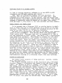


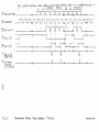
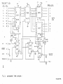
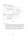

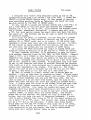

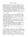
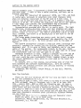


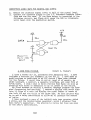

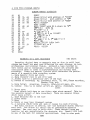
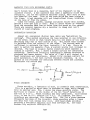


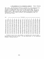
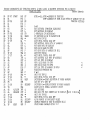
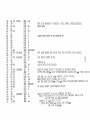
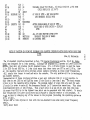


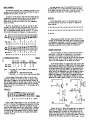
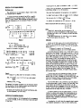

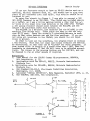


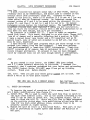
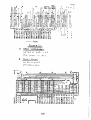

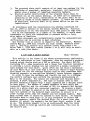
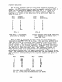
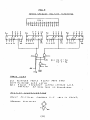
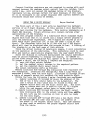


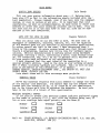
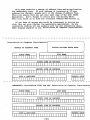
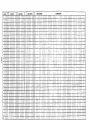


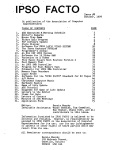


![Umted State Patent [19] [11] 4,142,232](http://vs1.manualzilla.com/store/data/005874596_1-c39d4064b00ab778afe28c128abc9f97-150x150.png)