1
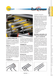
USER MANUAL Manual Code: D31029CG00 Contactless tool checking system for numeric control machines This product conforms to the requirements of the European Directive 2004/108/CE (EMC) The following standards have been applied: • EN 61326-1 This product is intended for operation in industrial environments; it is not intended to be connected to a public mains electricity supply but to a power supply betwork derived from a high or medium voltage transformer. The following Electrical Safety Standards have been applied: EN 61010-1 EN 60825-1 This product conforms to the USA regulation 21 CFR 1040.10 concerning lasers. Manufacturer MARPOSS S.p.A. Address Via Saliceto, 13 - Bentivoglio (BO) Italy www.marposs.com Type of equipment - model Mida Laser 75P Function Contactless tool checking for machining centres and milling machines Manual code D31029CG00 Issued 01/2009 Edition 07/2013 MARPOSS S.p.A. is not obliged to notify customers of subsequent modifications to the product. The descriptions in this manual in no way authorise tampering by unauthorised personnel. Copyright Marposs S.p.A. 2009-2013 2 MIDA LASER 75P – OPERATION MANUAL About Directive 2002/95/EC “RoHS” on the restriction of the use of certain hazardous substances in electrical and electronic equipment. The Member States of the European Community are completing the process of adoption and application of Directive 2002/95/EC on the restriction of the use of certain hazardous substances in electrical and electronic equipment. The Directive expressly excludes finished products such as those made and sold by Marposs. It is still widely debated whether or not completely removing the substances in question may interfere with product reliability. Marposs shares the social responsibility of continuously supporting all forms of innovation which reduce any risk of a harmful impact on human health and the environment. Therefore, Marposs will voluntarily continue to gradually remove harmful substances from its product. Marposs will pursue this objective with the clear understanding that any improvement in protecting health and the environment must not mean compromising product quality and reliability. Marposs will seriously take into consideration any initiative that its Customers undertake with the aim of reducing environmental risk. We are committed to supporting their efforts by developing products which are of the highest quality and reliability. MIDA LASER 75P – OPERATION MANUAL 3 Contents 1. GENERAL RULES AND INSTRUCTIONS 5 1.1 Precautions when using a Laser device ................................................................................. 5 1.2 Introduction ............................................................................................................................. 6 1.3 Warranty ................................................................................................................................. 6 2. OVERVIEW 7 2.1 System functions and operating principle ............................................................................... 7 2.2 Description of the technology used......................................................................................... 7 2.3 Possible applications .............................................................................................................. 8 2.4 Description of system components ......................................................................................... 8 2.4.1 Gauging probe, Modular version - Emitter ........................................................................ 9 2.4.2 Gauging probe, Modular version - Receiver...................................................................... 9 2.4.3 Gauging probe Stand Alone version on support ............................................................. 10 2.4.4 Connecting cable............................................................................................................. 11 2.4.5 Electronic interface.......................................................................................................... 11 2.4.6 Support for fixing the Stand Alone version in the machine.............................................. 12 2.4.7 Air treatment unit ............................................................................................................. 13 2.4.8 Gauging software cycles on NC ...................................................................................... 13 2.4.9 Calibrating tools............................................................................................................... 14 2.4.10 PC configuration software (ML ToolKit)......................................................................... 14 3. MAINTENANCE 15 3.1 Checking the optical windows and shutters .......................................................................... 15 3.2 Cleaning the pneumatic system filters .................................................................................. 16 3.3 Procedure for automatic gain adjustment ............................................................................. 16 3.3.1 Maintenance using software............................................................................................ 16 4. TROUBLESHOOTING 17 4 MIDA LASER 75P – OPERATION MANUAL 1. GENERAL RULES AND INSTRUCTIONS 1.1 Precautions when using a Laser device The Mida Laser system emitter uses as a light source a Laser diode with visible emission (670 nm wavelength). The maximum optical power emitted is < 1 mW, which means that the device is in class 2 according to international regulations, shown on page 2, to which we refer you for safety regulations and the relative precautions for use. In particular, we recommend: you must avoid exposing the human eye to the laser beam, whether direct or reflected by optical devices (mirrors, prisms, etc.) deliberately pointing the laser beam at people working nearby is strictly prohibited you must activate the laser beam and relative protective devices (shutters) only for the time necessary for set-up and/or use you must link the laser enabling signal to the safety devices of the machine on which it is installed (doors, panels, etc.) that you secure the labels explaining how to use the laser devices, which are supplied with the system and illustrated below, on the machine so that they are clearly visible you must ensure that all personnel are informed of these operating procedures. MIDA LASER 75P – OPERATION MANUAL 5 1.2 Introduction This instruction manual provides all specific information needed to familiarise yourself with and correctly use the MARPOSS equipment in your possession. THE PURCHASER MUST ENSURE THAT THE CONTENT OF THE MANUAL IS READ BY PERSONS RESPONSIBLE FOR INSTALLING, USING AND MAINTAINING THE EQUIPMENT. The information in the manual is aimed at the following categories of people: MARPOSS or Customer personnel directly responsible for installing the equipment. Customer technical personnel directly responsible for operating the MARPOSS equipment for production purposes. Customer technical personnel responsible for maintenance on the production line in which the MARPOSS equipment is included. This manual is an integral part of the equipment and therefore must be kept intact and made available to the User for the entire working life of the equipment. The manufacturer’s responsibility is limited to correct use of the equipment, within the limits indicated in this manual and its appendices. All rights reserved. This manual may only be reproduced for internal use by the purchaser. Any other use is prohibited. 1.3 Warranty The Marposs S.p.A. warranty covers defects in the materials and manufacturing defects. WARRANTY PERIOD: the warranty covers all repairs for Products carried out within the periods indicated in the sale contract. Equipment requiring repairs must be sent to the nearest Marposs Distributor. WHAT IS COVERED BY THE WARRANTY: the warranty applies to products or their components, marked with serial numbers or other identification systems used by the Company. The warranty shall be invalidated if unauthorised persons carry out any work on the equipment supplied. The warranty described above is valid unless alternative agreements are reached between the Distributor and the Customer. 6 MIDA LASER 75P – OPERATION MANUAL 2. OVERVIEW 2.1 System functions and operating principle The Mida Laser contactless gauging system allows a tool integrity check, tool wear check and compensation, tool length gauging, Static and Dynamic tool diameter gauging, tool identification, machine axes thermal drift compensation, cutting edge profile check and tool RUN OUT check. The system basically consists of a high precision Laser beam and a photodiode. The signals generated by the system, following interruption of the Laser beam, are used by the machine CNC to carry out the necessary gauging operations. 2.2 Description of the technology used The equipment consists of a visible light Emitter which is a Laser diode for its generation and the optical parts necessary for collimating/focusing the light beam; a Receiver equipped with a photodiode for receiving the light signal and the electronic circuit for processing the information associated with it. Electrical signals generated by the system after interruption of the laser beam are used by the machine CNC to carry out gauging operations. The system has pneumatic shutters designed to protect the emitter and receiver optical windows from all polluting factors which may exist in the machine environment (coolants, vapours, condensation, shavings, dusts, etc.). A pneumatic piston prevents access to the optical windows when the system is not operating. The shutter is only opened for the time necessary for gauging. Further protection is provided by an air barrier (suitably filtered) applied in front of the two optical windows. The air barrier is constantly present and, thanks to the new design of the protection system nozzle, it generates an air tunnel propagated over several centimetres, which surrounds and protects the laser beam. The Mida Laser gauging system protection rating is IP67. The Mida Laser measurement system is capable of measuring tools with a minimum dimension of 0.03 mm, with a repeatability of 0,2 µm* (2), and tools with smaller diameters depending on the threshold. The maximum distance between the Emitter and the Receiver is up to 3 m for the module version with collimated laser beam, 1 m for the focused modular version, and 415 mm in the Stand Alone version. *depending on the repeatability of the machine axes. The equipment is available in two versions: Modular separate emitter and receiver can be mounted in any area of the machine Stand Alone emitter and receiver mounted on a dedicated support MIDA LASER 75P – OPERATION MANUAL 7 2.3 Possible applications Typical areas of application are numeric control machines, in particular machining centres and milling machines. Machining centres. In machining centres, thanks to the greater repositioning reliability of the taper – spindle system, tool gauging is normally carried out in the tool-room using projectors and only rarely on the machine. However, all users always have to check tool integrity on the machine at the end of the machining cycle. Tool wear checking is not considered extremely critical since on production machines the tool life is planned in terms of hours or operating cycles and any abnormal wear is easily detected by power absorption sensors mounted on the spindle. Milling machines On milling machines, particularly those widespread in the diesinker sector, much more importance is attached to the need for tool wear checks, since tools are normally used for much longer periods during the cycle. On these machines, as is sometimes the case on machining centres, the tool length and diameter therefore have to be gauged. Other checks consist of checking that the appropriate tool has been loaded on the machine (identification) before starting machining, or gauging every single insert for milling machines with multiple cutting edges. The main advantage of Mida Laser probes is a contactless check of moving tools, therefore guaranteeing a noticeable reduction in machine down times and avoiding the risk of collision. 2.4 Description of system components Mida Laser gauging system component parts: Gauging probe (Modular or Stand Alone version) Connecting cable Electronic interface Supports for fixing probe in machine Air treatment unit NC gauging software cycles Calibrating tools Software on PC for configuration, set-up, maintenance (ML ToolKit) 8 MIDA LASER 75P – OPERATION MANUAL 2.4.1 Gauging probe, Modular version - Emitter 1 2 1. Laser beam output hole 2. Pneumatic shutter 3 3. Multi-colour LED 4. Connector for electric connecting cable 5. Pneumatic shutter air input 6. Barrier air input 4 5 6 2.4.2 Gauging probe, Modular version - Receiver The receiver is not affected by laser beam focusing or collimating features. 1 2 1. Laser beam input hole 3 2. Pneumatic shutter 3. Multi-colour LED 4. Connector for electric connecting cable 5. Pneumatic shutter air input 6. Barrier air input 4 5 MIDA LASER 75P – OPERATION MANUAL 6 9 2.4.3 Gauging probe Stand Alone version on support This version consists of the Emitter and the Receiver described in the previous sections, mounted on a dedicated support. It is available with different linear dimensions (see section). The power sources for the pneumatic circuits, control of the shutter and air barrier are the same as in the Modular version, the difference being that they are only present on the Receiver, in particular on the cover behind the module. There is also only one connector for the cable which connects to the interface. Said connector is below the Receiver box. C B A A. Support or beam for mounting a Receiver and an Emitter separated by a preset distance (Stand Alone version) B. Connector for electric connecting cable C. Pneumatic circuits power supply Available in 12 versions, with different base length and emitter type: 1. 2. 3. 4. 5. 6. 7. 8. 9. 10. 11. 12. 10 136 mm support and focused laser beam with lateral cable outlet 165 mm support and focused laser beam with lateral cable outlet 165 mm support and focused laser beam with central front cable outlet 165 mm support and focused laser beam with central bottom cable outlet 215 mm support and focused laser beam with lateral cable outlet 215 mm support and focused laser beam with central front cable outlet 215 mm support and focused laser beam with central bottom cable outlet 295 mm support and focused laser beam with lateral cable outlet 295 mm support and focused laser beam with central front cable outlet 295 mm support and focused laser beam with central bottom cable outlet 415 mm support and focused laser beam with central lateral outlet 415 mm support and focused laser beam with central bottom outlet MIDA LASER 75P – OPERATION MANUAL 2.4.4 Connecting cable The gauging probe connects to the electronic interface using the cable whose length and connectors vary depending on mounting requirements. Figure 2-1. Stand Alone version cable Figure 2-2. Modular version cable Important: 2 cables for each module are supplied for the Modular version. 2.4.5 Electronic interface Mida Laser 75P gauging probes interface with the machine, with the CNC and the PLC, via an electronic interface to be integrated in the electrical cabinet. Figure 2-3. Interface MIDA LASER 75P – OPERATION MANUAL 11 2.4.6 Support for fixing the Stand Alone version in the machine Figure 2-4. Mounting plate. For table installation of Stand Alone versions with a lateral cable outlet we recommend the use of special plates, shown in Figure 2-4. Mounting plate. The plates may be fitted with optional tool cleaning devices which guarantee that gauging is performed in the best conditions, particularly when gauging after machining with coolant (Plate code 11T0439784, plate + cube blower kit code 29T0439784, plate + tube blower kit code 29T0439785). The cube blower has the advantage of not taking up any space inside the gauging area, even allowing the tool to pass through the snap gauge. The tube blower is more directional and provides greater cleaning power because it can operate close to the tool. In the case of highly critical conditions it is possible to increase the blower power by connecting two Tool Cleaners to the same plate. In this case, the second Tool cleaner will be as shown in Figure 2-5. Blower and must be positioned so that it faces the tool, by adjusting the height tilt and distance from the tool as required. Figure 2-5. Blower 12 MIDA LASER 75P – OPERATION MANUAL 2.4.7 Air treatment unit Mida Laser systems have double protection against machining residues from shavings removal on machine tools and the presence of coolants: Pneumatically operated mechanical shutter Air barrier The shutter mechanically prevents the unwanted passage of shavings and coolant towards the optical parts. The air barrier pressurises the protection system and generates a continuous air jet towards the outside, increasing its impermeability. During tool gauging the protection level is guaranteed by a technology based on the use of an air tunnel which surrounds the laser beam, creating a filter for drops of coolant. An optional Kit is available with a blower for cleaning tools which increases the system gauging capacity in the presence of large quantities of coolant and shavings. All of the protection devices described can be activated by a single filter unit which has 3 functions: shutter opening/closing control, regulation of barrier air flow and control of tool cleaning blower Kit. The filter unit (code 29T0443050) is supplied as an optional item but we recommend it if you want precision gauging even in the presence of drops of coolant. The filter unit can also be mounted in two modules, in order to reduce the horizontal dimensions. The accessories required for mounting it in this way are supplied in the kit part number 29T0443050. 2.4.8 Gauging software cycles on NC MIDA LASER 75P – OPERATION MANUAL 13 The synergy between Mida Laser and the Marposs gauging Macro allows fast, reliable tool presetting. Tool dimensions are obtained or checked at the actual speed of rotation, with the tool mounted on the spindle, as it is during machining. 2.4.9 Calibrating tools To use the Mida Laser system a calibration cycle must be carried out using the appropriate program supplied on the NC, fitting one of the Marposs gauges on the spindle. Figure 2-6. Calibrating tools The calibration cycle permits to accurately identify the measuring point. 2.4.10 PC configuration software (ML ToolKit) The software application, supplied with ML, is used for the following procedures: Installation Configuration Maintenance 14 MIDA LASER 75P – OPERATION MANUAL 3. MAINTENANCE The Mida Laser does not require any special maintenance. It is good practice to regularly check that the system is clean, paying particular attention to the emitter and receiver optical windows. If the “Laser OK” signal is lost or if there is a drop in gauging precision, we recommend that you follow the procedures described below. 3.1 Checking the optical windows and shutters Remove the shutters (A) from the Receiver and Emitter module and check the state of the seal (E). Clean the optical parts (B) with a suitable optical cleaning cloth or papers. Any traces of dirt and/or grease can be removed using suitable liquid detergents and anhydrous compressed air sprays. Unscrew the screws of the Shutter closing cap (C) and check that the piston and the cavity inside it are clean and can slide freely inside each other. Only perfect piston (D) cleaning allows correct shutter opening and closing, guaranteeing Laser system protection during machining and its operation during gauging. After inspecting and cleaning, put the spring and piston back in and tighten the cap with the two screws. Carefully position the seal in its seat and screw the shutters onto the two modules. Each time maintenance work is carried out, run the calibration cycle using the Part Program from the CNC. B E C D A Figure 3-1: Check of optical windows and shutters MIDA LASER 75P – OPERATION MANUAL 15 3.2 Cleaning the pneumatic system filters Pneumatic systems are normally equipped with discharge devices which guarantee cleanliness. However, we recommend that at least once a year you thoroughly clean the pneumatic system filters (using compressed air or substituting the cartridge). 3.3 Procedure for automatic gain adjustment The Mida Laser 75P automatically adjusts the receiver gain to guarantee the light conditions for each gauging operation. The adjusting system only intervenes if the light level at switch on exceeds the Laser OK threshold, otherwise the output signal is not generated. 3.3.1 Maintenance using software The “Laser Tool Kit” application software allows system maintenance to be carried out and in particular identification of the source of and solutions for any faults. The “Trace Tool” function key can be used to display the last touches acquired and saved on the interface. Analysis of the data collected allows the identification of any faults which occurred during gauging cycles. Interpretation of the data must be supported by specialised personnel. The left-hand window above shows the typical trend of a milling cutter with five cutting edges, of which one is missing, rotating inside the laser beam in a fixed position. The “I/O Test” function key opens a window, shown above on the right-hand side, from which you can activate and disable the outputs and read the inputs so as to evaluate how they are actually operating. 16 MIDA LASER 75P – OPERATION MANUAL 4. TROUBLESHOOTING FAULTS All the LEDs on the interface are extinguished No power supply The Firmware Start Up is in progress and only the orange LED at the bottom of the panel should be flashing LED 2 Red Power supply circuit fault Check the power supply voltage (see electrical specifications paragraph 3.1.4Installation Manual-) LED extinguished on Emitter and Receiver modules No power supply to modules or snap gauge Check the power supply is present at the interface Check that the cable(s) is/are connected to C2 on the interface Check the cables between the interface and the modules or the snap gauge (see electrical connections paragraph 4.3.3 -Installation Manual-) check that the orange pin13 LED is illuminated check that the signal is present on pin13 (e.g.24V) if pin13 is connected to the PLC, supply the enable output M-Code check that the orange LED on the Emitter module is illuminated check that the shutters have opened Check the mains air pressure Set up the air barrier pressure to 1.5 bar less than the shutter control air Remove the shutters, if the laser is extinguished contact your Marposs service centre No laser beam The shutters do not open: POSSIBLE CAUSE Pin13 not enabled Emitter module faulty usually it is easy to verify this condition because the sudden pressure increase that can be felt by placing a hand over the air flow, and which indicates that the shutters have opened, is absent Output signal absent (Laser Ok, Dynamic, Static) No shutter control air pressure Shutter control air pressure too low Dirt on the optics Modules misaligned Receiver module faulty No laser beam MIDA LASER 75P – OPERATION MANUAL REMEDY Check the power supply voltage between pins 1 and 2 (24V) Check the LED corresponding to the output on the interface: LED Red: output faulty LED Green: output active, check the cables that connect it to the machine (the LED should switch on and off depending on whether the beam is interrupted or not) If the LED on the interface is 17 permanently illuminated or extinguished, even when the laser beam is interrupted intermittently: check that the LED on the receiver module is Orange when the beam is not interrupted and Green when it is interrupted. If it is Red: No measurement signal (skip) Dynamic output Poor repeatability Dynamic output (pin 9) not enabled Receiver power supply fault Modules misaligned (see paragraph 4.5 -Installation Manual-) Dirt on the optics (see paragraph 3.1) check that the orange pin 9 LED is illuminated check that the signal is present on pin 9 (e.g.24V) if pin 9 is connected to the PLC, supply the enable output M-Code check that interrupting the laser beam causes the output to vary increase the pulse duration(see paragraph 4.4-Installation Manual-) Module fixing screws not tightened correctly Tighten the module or snap gauge fixing screws correctly Presence of shavings or coolant on the tool tip Remove the dirt with a tool cleaning blower (see paragraph 2.4.6) The gauging speed is to fast for the machine control Repeat the repeatability test at various speed Excessive machine vibrations Eliminate the vibrations Poor machine repeatability due to encoders that have worked loose, play, narrow and/or accidentally damaged slides Check the state of the machine thoroughly Table 4-1 LED fault indications LED IN0 IN1 IN2 IN3 IN4 ERROR TYPE Fatal error during internal HW initialisation phase Fatal error in the output LEDs management Checksum error on the data backup Flash Checksum error on the gain saving RX EEprom RX access error ********************************************End of Document*********************************************** 18 MIDA LASER 75P – OPERATION MANUAL Notes: Printed in Italy