1
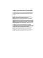
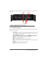
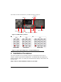
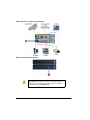
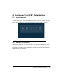
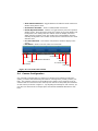
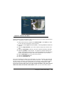
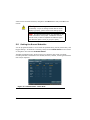
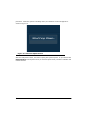
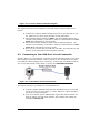
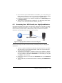
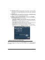
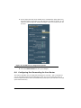
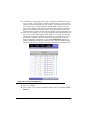
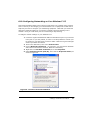
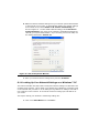
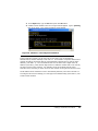
Tempest Digital Video Recorder Installer Guide
The content of this manual is furnished for informational use only, is
subject to change without notice as is and may include errors or
inaccuracies. No part of this publication may be reproduced without
permission.
THIS PROUDCT IS PROVIDED ON AS IS BASIS. THERE ARE NO
MANUFACTURER WARRANTIES, EXPRESS OR IMPLIED, INCLUDING
WITHOUT LIMITATION THE IMPLIED WARRANTIES OF
MERCHANTABILITY AND FITNESS FOR A PARTICULAR PURPOSE,
REGARDING TEMPEST SOFTWARE.
THE ENTIRE RISK AS TO THE RESULTS AND PERFORMANCE OF THIS
TEMPEST PRODUCT IS ASSUMED BY THE USER. THE EXCLUSION OF
IMPLIED WARRENTIES IS NOT PERMITTED BY SOME STATES. THE
ABOVE EXCLUSION MAY NOT APPLY TO YOU.
BY USING THIS PRODUCT YOU ASSUME FULL RISK FOR ANY
CONSEQUENTIAL, INCIDENTAL, OR INDIRECT DAMGES (INCLUDING
DAMGES FOR LOSS OF BUSINESS PROFITS, BUSINESS
INTERRUPTION, LOSS OF BUSINESS INFORMATION, AND THE LIKE)
ARISING OUT OF THE USE OR INABILITY TO USE THE PRODUCT.
BECAUSE SOME STATES DO NOT ALLOW THE EXCLUSION OR
LIMITATION OF LIABILITY FOR CONSEQUENTIAL OR INCIDENTAL
DAMGES, THE ABOVE LIMITATIONS MAY NOT APPLY TO YOU.
TABLE OF CONTENTS
1
Introducing Your Network DVR ............................................ 1
1.1
2
8000 Series Hardware Overview .......................................... 2
2.1
2.2
3
Package Contents . . . . . . . . . . . . . . . . . . . . . . . . . . . . . . . . . . . . . . 1
Front Panel Features . . . . . . . . . . . . . . . . . . . . . . . . . . . . . . . . . . . . 2
I/O Panel Features . . . . . . . . . . . . . . . . . . . . . . . . . . . . . . . . . . . . . 2
9000 Series Hardware Overview .......................................... 4
3.1
3.2
Front Panel Features . . . . . . . . . . . . . . . . . . . . . . . . . . . . . . . . . . . . 4
I/O Panel Features . . . . . . . . . . . . . . . . . . . . . . . . . . . . . . . . . . . . . 4
4
Installation Procedures ........................................................ 6
5
Configuring Your DVR’s Initial Settings .............................. 10
5.1
5.2
5.3
5.4
5.5
5.6
6
Bootup Sequence . . . . . . . . .
Setting Time and Date . . . . . .
Viewing the Live Feed . . . . . .
Camera Configuration . . . . . .
Setting the Record Schedule . .
Shutting Down/Rebooting Your
....
....
....
....
....
DVR
.
.
.
.
.
.
.
.
.
.
.
.
.
.
.
.
.
.
.
.
.
.
.
.
.
.
.
.
.
.
.
.
.
.
.
.
.
.
.
.
.
.
.
.
.
.
.
.
.
.
.
.
.
.
.
.
.
.
.
.
.
.
.
.
.
.
.
.
.
.
.
.
.
.
.
.
.
.
.
.
.
.
.
.
.
.
.
.
.
.
.
.
.
.
.
.
.
.
.
.
.
.
.
.
.
.
.
.
.
.
.
.
.
.
.
.
.
.
.
.
.
.
.
.
.
.
.
.
.
.
.
.
.
.
.
.
.
.
.
.
.
.
.
.
10
10
11
13
15
16
Setting Up Your DVR on the Network ................................. 18
6.1
6.2
6.3
6.4
6.5
6.6
6.7
6.8
6.9
6.10
6.11
Connecting Directly to Your DVR Using a Crossover Cable
Connecting to Your DVR Over a Local Connection . . . . . .
Connecting Your DVR Directly to a High Speed Modem . .
Connecting Your DVR to the Internet Using a Router . . . .
Configuring Your DVR’s Network Settings . . . . . . . . . . . .
Testing Your Network Connection . . . . . . . . . . . . . . . . .
Using the Tempest Remote Access Server . . . . . . . . . . .
Using the Tempest Health Server . . . . . . . . . . . . . . . . .
Configuring Port Forwarding On Your Router . . . . . . . . . .
Configuring Networking on Your Windows™ PC . . . . . . . .
Looking Up Your Network Settings on a Windows™ PC . . .
.
.
.
.
.
.
.
.
.
.
.
.
.
.
.
.
.
.
.
.
.
.
.
.
.
.
.
.
.
.
.
.
.
.
.
.
.
.
.
.
.
.
.
.
.
.
.
.
.
.
.
.
.
.
.
.
.
.
.
.
.
.
.
.
.
.
.
.
.
.
.
.
.
.
.
.
.
.
.
.
.
.
.
.
.
.
.
.
.
.
.
.
.
.
.
.
.
.
.
18
19
20
21
22
24
25
26
27
30
31
7
Selecting Compatible Equipment ........................................ 33
7.1
7.2
7.3
7.4
7.5
7.6
8
.
.
.
.
.
.
.
.
.
.
.
.
.
.
.
.
.
.
.
.
.
.
.
.
.
.
.
.
.
.
.
.
.
.
.
.
.
.
.
.
.
.
.
.
.
.
.
.
.
.
.
.
.
.
.
.
.
.
.
.
.
.
.
.
.
.
.
.
.
.
.
.
.
.
.
.
.
.
.
.
.
.
.
.
.
.
.
.
.
.
.
.
.
.
.
.
.
.
.
.
.
.
.
.
.
.
.
.
.
.
.
.
.
.
.
.
.
.
.
.
.
.
.
.
.
.
.
.
.
.
.
.
33
33
34
34
34
35
Tools and Testing Procedures............................................. 36
8.1
8.2
8.3
8.4
9
Cameras and Cabling . . . . . . . . . . . . .
Video Display . . . . . . . . . . . . . . . . . .
Surge Protector/Voltage Regulator/UPS
Surge Protectors . . . . . . . . . . . . . . . .
Voltage Regulators . . . . . . . . . . . . . .
Uninterruptible Power Supplies (UPS) .
Tools to Bring to the Install Site . . . . . . .
Avoiding Ground Loops . . . . . . . . . . . . .
Checking For Correct Video Signals . . . . .
Troubleshooting Your Network Connection
.
.
.
.
.
.
.
.
.
.
.
.
.
.
.
.
.
.
.
.
.
.
.
.
.
.
.
.
.
.
.
.
.
.
.
.
.
.
.
.
.
.
.
.
.
.
.
.
.
.
.
.
.
.
.
.
.
.
.
.
.
.
.
.
.
.
.
.
.
.
.
.
.
.
.
.
.
.
.
.
36
37
37
38
Troubleshooting/FAQ ......................................................... 40
9.1
9.2
Common DVR Problems and Solutions . . . . . . . . . . . . . . . . . . . . . . . 40
Interceptor and Web Browser . . . . . . . . . . . . . . . . . . . . . . . . . . . . . 42
1
Introducing Your Network DVR
Congratulations on your purchase of a Tempest network Digital Video Recorder (DVR).
With this DVR, the number of applications are limited only by your very own
imagination. Pre-installed with all required software, your DVR is ready to be used right
out of the box. This guide will explain how to setup and configure your DVR, and will
give you useful advice to help you avoid common installation problems. Please refer to
the user's manual for specific details on how to operate your DVR.
Your DVR is an advanced recording and monitoring device designed to give you years of
trouble free service when operated in a clean and conditioned environment. Taking
proper care to install your DVR correctly and configure it to best meet your specific
requirements will help ensure a smooth, efficient installation and long lifetime of your
DVR. This guide is intended for experienced installers. People who do not have
significant experience installing cameras and wiring or setting up and configuring
networking equipment should seek appropriate help from qualified electricians and/or
network technicians. Please be sure to read through this entire install guide carefully
before you begin installing your DVR, and consult the DVR user guide as necessary.
1.1
Package Contents
The following items are included in your Tempest DVR package:
1. Network DVR
2. Cables
• Power cord
•
•
S-Video to RCA adapter
RCA to BNC adapter
3. Accessories
• IR remote and receiver module
• Mouse
4. Documentations
• User guide
• Installation guide
5. Application CDs
• Tempest Microsystems Interceptor™ client software CD
•
•
Tempest Microsystems Tsunami™ server CD
Tempest Microsystems Custom install CD
Introducing Your Network DVR
1
2
8000 Series Hardware Overview
This section outlines the hardware features and port connections of Tempest 8000 Series
DVRs. If you are using a Tempest 9000 Series, please skip this section and refer to
Section 3 instead.
2.1
Front Panel Features
The front panel of your DVR provides access to your CD-Writer, the power button and
the reset button. Status lights (LEDs) corresponding to the power and hard drive
activity of your unit can also be found on the front panel.
The locations of the various components found on the front panel of your DVR are shown
in Figure 1.
CD-Writer
Reset Button Hard Drive LED Power LED
Power Button
Figure 1. 8000 Series Front Panel
2.2
I/O Panel Features
The I/O panel contains all the connectors for connecting peripheral devices and cables.
These connectors include:
2
•
•
•
•
•
•
•
•
Video Inputs - The Video Inputs panel consists of BNC connectors for 4/8/
12 (See Figure 3) video inputs from cameras (NTSC/PAL) or other sources
(CCTV cameras, tuners, VCRs, etc.).
VGA Out - Video Graphics Array (VGA) monitor output.
TV Out - TV (NTSC/PAL) output
Audio Connectors - Audio input/output. The Line-in jack is designated by
a blue connector, Line-out jack by green and Microphone jack by red.
LAN - RJ-45 Ethernet port for local area network (LAN).
USB - Universal Serial Bus (USB) connector used for infra-red remote control
module.
Keyboard - PS/2 connector used for keyboard.
Mouse - PS/2 connector used for mouse.
The location of these connectors for your DVR are shown in Figure 2.
Audio Connectors
Mouse
TV Out
LAN
Power
Switch
Keyboard
Power Inlet
VGA Out
USB
Video Inputs
8000 Series Hardware Overview
3
Figure 2. Tempest 8000 Series I/O Panel
Model 804x
Model 808x
Model 812x
Figure 3. Video Inputs Diagram for Tempest 8000 Series
3
9000 Series Hardware Overview
This section outlines the hardware features and port connections of the 9000 Series
DVRs. If you are using an 8000 Series, please skip this section and refer to Section 2
instead.
3.1
Front Panel Features
The front panel of your DVR provides access to your CD-Writer, the power button and
the reset button. Status lights (LEDs) corresponding to the power and hard drive
activity of your unit can also be found on the front panel.
4
The locations of the various components found on the front panel of your DVR are shown
in Figure 4.
Power LED
CD-Writer
Hard Drive LED
Power Button
Reset Button
Figure 4. Tempest 9000 Series Front Panel
3.2
I/O Panel Features
The I/O panel contains all the connectors for connecting peripheral devices and cables.
These connectors include:
•
•
•
•
•
•
•
•
Video Inputs - The Video Inputs panel consists of BNC connectors for 8/12/
16 video inputs (See Figure 6) from cameras (NTSC/PAL) or other sources
(CCTV cameras, tuners, VCRs, etc.).
Audio Connectors - Audio input/output. The Line-in jack is designated by
a blue connector, Line-out jack by green and Microphone jack by red.
VGA Out - Video Graphics Array (VGA) monitor output.
TV Out - TV (NTSC/PAL) output
LAN - RJ-45 Ethernet port for local area network (LAN).
USB - Universal Serial Bus (USB) connector used for infra-red remote control
module.
Keyboard - PS/2 connector used for keyboard.
Mouse - PS/2 connector used for mouse.
9000 Series Hardware Overview
5
The location of these connectors for your DVR are shown in Figure 5.
TV Out
LAN
Mouse
Power Inlet
Keyboard
Power Switch
USB
Video Inputs
Audio Connectors VGA Out
Figure 5. 9000 Series I/O Panel
Model 908x
Model 912x
Model 916x
Figure 6. Video Inputs Diagram for Tempest 9000 Series
4
Installation Procedures
This section describes how to physically install your Tempest DVR and connect up
cameras, monitors, input devices, and Ethernet. To install the DVR, first unpack and
inspect the DVR to make sure nothing was damaged during shipping. Next perform the
following steps:
Step 1: Choose a safe installation location for your DVR
6
To ensure a long lifetime of your DVR, it is absolutely critical that you install it in a
friendly environment.
•
•
•
•
Do not install your DVR in a cupboard, closet, or other closed space where
there is not enough air circulation.
Make sure your DVR is kept in a cool, temperature-controlled environment at
all times, 24/7. Exposure to high temperatures will reduce the life of your
DVR’s hard drive.
Do not place your DVR in a place where it might be exposed to moisture, dirt,
or other hazardous elements.
Do not connect your DVR to a power line that is subject to line noise, brownouts, or power outages. Exposure to a bad power line will damage or reduce
the life of your DVR. See Section 7.5 for advice on conditioning your power
line.
Step 2: Connect video outputs and IR
Installation Procedures
7
Step 3: Connect cameras to video inputs
Warning: Ground loops or electrical problems with
your cameras/wiring can lead to freezing problems or
physical damage to your DVR. Before connecting them
to your DVR, check each camera feed for ground loops
or voltage problems. Also, test to make sure each
camera input has a proper video signal using a monitor
and/or a CCTV test meter. (See Section 8.2, Section
8.3)
8
Step 4: Connect Ethernet cable router/switch/hub/PC to LAN port
Step 5: Connect power cord to a UPS or surge protector outlet and into the
power inlet of the DVR
Installation Procedures
9
Step 6: Flip power switch to ON position
Step 7: Press the power button
Warning: Connect the unit to a UPS and/or surge
protector to protect from electrical surges and power
line problems (See Section 7.6).
10
5
Configuring Your DVR’s Initial Settings
5.1
Bootup Sequence
After you have powered up the unit, it will go through its initialization sequence (Figure
7). During this process, icons representing the System, Clock, Disk, Network and Web
Server will be highlighted as the system progresses through the boot up sequence.
Figure 7. DVR Software Initialization
5.2
Setting Time and Date
The first time you bootup your DVR, it will ask you to set the time and date. For proper
operation of the DVR, it is important to set the time and date correctly (Figure 8). An
incorrect time and date will make it difficult to interpret recorded files and to determine
the time events were recorded.
Configuring Your DVR’s Initial Settings
11
Figure 8. Time and Date Sub-Menu
To set the Time/Date:
1. Navigate to the Date textbox. Enter the month, day, and year using the
numerical keys on the remote.
2. Navigate to the Time textbox. Enter the time of day using a 24-hour format.
In the case of Figure 8, 13:06:06 represents 1:06:06 pm.
3. Select the Time Zone.
4. Select the Save button to save your changes.
5. After the settings are saved, restart the DVR by going to Systems > Shutdown > Restart.
5.3
Viewing the Live Feed
After physically installing your DVR, the first thing you should check is that all your
cameras show up properly. During normal operation of the DVR, it is possible to
simultaneously view all or a selected group of cameras in the Live Feed mode.
12
To select the Live Feed mode:
1. Press the Red button on the remote or select the Live Feed button on the
main navigation bar.
2. A live feed will automatically begin with detected cameras, as shown in Figure 9. By default, the DVR is setup to accept NTSC cameras. If the camera
type needs to be changed, please visit the Cameras menu (See ”Camera
Configuration” on page 14).
Stage
Live Feed Control Panel
Audio Channel Selection
Camera
Number
Figure 9. Live Feed Display
The Live Feed control panel is located on the bottom of the Live Feed screen. The
elements found in the control panel, shown in Figure 10, includes (from left to right):
•
•
•
Hide Button - Used to hide the menu bar. Once the menu bar is hidden, hitting any key on the remote will bring it back into view.
Version - Displays the Tsunami DVR software version.
Date/Time - Displays the current date and time.
Configuring Your DVR’s Initial Settings
13
•
•
•
•
•
Audio Channel Selection - Toggles between the different audio channels to
stream during the live feed.
Screensaver Checkbox - Used to enable/disable screensaver.
Preset/Dynamic Buttons - Buttons to toggle between preset and dynamic
display modes. Under the Preset mode, the number of live feed displays will
be adjusted to the settings that are defined under the Display sub-menu.
While using the Dynamic mode, the number of live feed displays will automatically be adjusted to the number of feeds that is selected in the Live Feed
Selection area.
Live Feed Selection - Area used to set/unset live feeds to display on the
screen.
Exit Button - Used to exit out of the Live Feed mode.
Screensaver
Version
Audio Channel Selection
Date/Time
Hide Button
Preset
Dynamic
Live Feed Selection
Exit Button
Figure 10. Live Feed Control Panel
5.4
Camera Configuration
It is extremely important that you adjust your camera record settings to match the
quality you desire while maximizing the amount of storage time you will get from your
DVR. The Cameras sub-menu in the Settings menu allows you to specify the type of
cameras that are connected to each video input as well as set the quality and resolution
of each camera, as shown in Figure 11. By adjusting the settings for each camera, you
may fine tune the amount of storage space and network bandwidth allocated to each
feed.
14
Figure 11. Cameras Sub-Menu
Camera settings can be adjusted for each individual camera or for all the cameras at the
same time. To adjust the camera settings:
1. Select which camera to adjust in the Camera field. Select All if you want
to have the same settings for all the cameras.
2. Select the camera Type (NTSC/PAL/NONE). Selecting NONE will disable the
camera.
3. Select the Flip checkbox if you wish to flip the image of the camera vertically.
4. Select the Resolution (160x120, 320x120, 320x240, 640x240, 640x480).
5. Adjust the Quality of each camera. The higher the quality selected, the
cleaner and sharper the feed will be. It is also important to note that higher
quality feeds will lead to larger sized video clips that the server records.
6. Select a PTZ Input if you are using a PTZ camera.
7. Select the PTZ Protocol type.
8. Select the PTZ Device #.
As you are adjusting the setting for an individual or a group of cameras, the result will
be shown in the window on the right of the Camera sub-menu. The estimated storage
will also change according to the settings that were entered. Entering different frame
rates and number of connected cameras will vary the available storage time. The
frame rate control in this menu is for the storage calculator only, and does not
affect the actual record rate of the camera. After you have entered the desired
Configuring Your DVR’s Initial Settings
15
values for all connected channels, navigate to the Save button and press OK on the
remote.
Warning: The camera type selection affects DVR
functionality. If you are having trouble with the feeds
displaying properly, please check these settings again.
Note: For optimum performance, it’s advisable to use
similar cameras for every input. If different cameras
must be used, it’s best to separate the different types
onto different capture cards (in groups or pairs).
5.5
Setting the Record Schedule
You can program the DVR to record video at specified times, periods, frame rates, and
trigger settings. To schedule a recording, first press the Yellow button on the remote
or navigate to and select the Schedule button.
The Basic scheduling mode, shown in Figure 12, allows for the setup of a simple
recording schedule. Parameters such as start/end time, channel, record type and frame
rate may be adjusted.
Figure 12. Schedule Menu - Basic Mode
16
To program a recording schedule in Basic mode:
1. Select the Basic button under the Schedule menu.
2. Select the channel to which the particular schedule will apply. If the schedule is to be the same for all active channels, select All Channels.
3. Select the 24/7 checkbox if you wish to continuously record 24 hrs a day,
7 days a week. Otherwise, specify the times you would like to record by setting the Start and End times for each day of the week.
4. Select the type of recording. The Record Type can either be Continuous,
On Motion, or Custom.
5. Enter the frame rate at which the DVR is to record at in the FPS textbox.
The higher the rate, the smoother the feed and the greater the size of the
recorded clip.
Note:
Selecting the same Start and End time will cause the
DVR to not record on the specified channel(s). Start and End
time are based on a 24-hour time format, with 00:00:00 being
12:00 am and 23:59:59 being 11:59:59pm.
The On Motion record type will give you a much larger record duration from your hard
drive, but will result in gaps in your recordings where there is no motion present. To
extend the record duration of your hard drive without leaving gaps in your recordings,
you can setup smart recording. To setup smart recording, set the Record Type to
Custom, then set the continuous frame rate to 1 fps and set the motion frame rate to
30 fps.
After you have set the schedule, save it by navigating to the Save button and press the
OK button on the remote to save your changes. You may also clear the current
schedule by navigating to the Clear button and pressing the OK button on the remote.
5.6
Shutting Down/Rebooting Your DVR
Your DVR should always be shutdown using the software interface, rather than by
physically cutting power to the device. Shutting down your DVR without using the
software can lead to data corruption. The DVR may be shutdown or rebooted in the
Shutdown sub-menu. To reach the Shutdown sub-menu:
1. Click the red Power button on the remote.
2. Navigate to the System menu and select the Shutdown button.
Once the Shutdown sub-menu appears, click on the Shutdown button or the Restart
button as required. Shutting down the DVR will take approximately 15 seconds, at
which point the system will use this time to close files and terminated remaining
Configuring Your DVR’s Initial Settings
17
processes. While the system is shutting down, the shutdown screen will appear as
shown in Figure 13.
Figure 13. Shutdown Splash Screen
After the DVR powers down, it is safe to unplug the system’s power. If you selected the
Restart button in the System screen, it would not power down, but will re-initialize and
restart the DVR.
18
6
Setting Up Your DVR on the Network
Tempest DVRs support many powerful features that are accessible from a distant
location over the Internet, including viewing live video, reviewing previously recorded
video clips, and configuring DVR settings. Although our DVRs are designed to be as
simple as possible to setup on the network, depending on your installation site, you may
be trying to integrate your DVR with different pieces of network equipment, different
types of Internet connections, and different types of security settings. As a result, when
you setup your DVR on the network, it is absolutely critical that you have an experienced
network technician present who understands what type of equipment you are using and
how to configure it.
In Section 6.1-Section 6.4, the four most common network setups and the typical
steps used to configure your DVR on those kind of networks are outlined.
•
•
•
•
Section 6.1 describes the steps used to connect your DVR directly to a PC
using a crossover cable.
Section 6.2 describes how to connect to your DVR through a local connection without going out onto the Internet.
Section 6.3 describes the steps to setup your DVR on the Internet by
directly connecting it to a cable or DSL modem.
Section 6.4 describes the steps to setup your DVR on the Internet using a
router and an Internet connection.
You would need to determine which of the four sections matches the network setup you
wish to use, then follow the instructions in that section.
6.1
Connecting Directly to Your DVR Using a Crossover
Cable
A crossover cable connection can be useful for testing your DVR’s networkability, and
involves a direct connection between your PC and DVR, as shown in Figure 14. A
crossover cable is not a regular CAT5 Ethernet cable. Only a cable explicitly
labeled as a crossover cable will work.
Setting Up Your DVR on the Network
19
Figure 14. Crossover Cable Connection Diagram
The steps to connect over the network to your DVR using a crossover cable are as
follows:
1. Connect the crossover cable to the Ethernet port on your DVR and on your
PC. Make sure you see a green link light on both connections.
2. Set the DVR’s network settings to Static, with the following settings: IP =
192.168.1.200, Gateway = 192.168.1.1, Subnet = 255.255.255.0 See Section 6.5 for instructions on how to do this.
3. Set the PC’s network settings to Static, with the following settings: IP =
192.168.1.201, Gateway = 192.168.1.1, Subnet = 255.255.255.0 See Section 6.10 for instructions on how to do this.
4. From your PC, connect into your DVR at IP 192.168.1.200 using either a web
browser, or the Interceptor Remote Software (blue CD).
6.2
Connecting to Your DVR Over a Local Connection
Shown in Figure 15, a local network connection involves connecting locally to your DVR
without going out onto the Internet. This is useful if you are connecting to your DVR
from within the same building, store, or business. In this setup, your DVR connects to
one or more PCs through a hub, switch, or router using CAT5 Ethernet cables.
Figure 15. Local Network Connection Diagram
The steps to connect to your DVR over a local network are:
1. Connect a regular CAT5 Ethernet cable into the Ethernet port on your DVR
and to a port on your hub, switch, or router. Make sure a green link light
shows up on both connections.
2. From your network system administrator, request the desired network settings for adding your DVR to the network, and configure the settings as
described in Section 6.5.
20
3. If your network system administrator is unavailable, you can try setting your
DVR’s settings to DHCP, or can try to guess them by looking up the network
settings on your Windows™ PC using ipconfig (see Section 6.11).
4. Lookup the IP address of your DVR by navigating to the Status Page under
the Settings Menu.
5. From your PC, connect into the IP address of your DVR using either a web
browser, or the Interceptor Remote Software (blue CD).
6.3
Connecting Your DVR Directly to a High Speed Modem
This section describes how to setup your DVR on the Internet by connecting your DVR
directly into a high speed modem, e.g. a DSL or cable modem, as shown in Figure 16.
This is useful if you have a DSL or cable modem, and your Internet connection is
devoted to your DVR and not shared by any other devices.
Figure 16. High Speed Broadband Connection Diagram
The steps to setup your DVR on the Internet by connecting directly to a high speed
modem are:
1. Connect a regular CAT5 Ethernet cable into the Ethernet port on your DVR
and into a port on your high speed modem. Make sure a green link light
shows up on both connections.
2. Consult the documentation or customer service of your modem or Internet
Service Provider to obtain your DVR’s desired network settings, and configure your settings as described in Section 6.5. In most cases, you may also
use DHCP for your settings.
3. Select a host name for your DVR in the Host Name Menu (see Section 6.7
for details)
4. Test to make sure your Internet connection is working (see Section 6.6 for
details)
Setting Up Your DVR on the Network
21
5. From your PC, connect into the host name of your DVR using the Interceptor
Remote Software (blue CD) or a web browser.
Note:
If your high speed modem has a built-in router or
firewall, you will need to setup port forwarding on your modem.
Refer to Section 6.9 for details on how to do this.
6.4
Connecting Your DVR to the Internet Using a Router
This section describes how to setup your DVR on the Internet using a router, which can
be connected to a DSL or cable modem, as shown in Figure 17. This is useful if you have
a single Internet connection that can be shared with one or more computers and your
DVR. Note that streaming video is a bandwidth intensive operation, and it is highly
recommended that you devote an entire high speed Internet connection to your DVR.
Figure 17. Broadband Connection with Router Diagram
The steps to setup your DVR on the Internet using a router are:
1. Connect a regular CAT5 Ethernet cable into the Ethernet port on your DVR
and into a port on your router. Make sure a green link light shows up on
both connections.
2. Consult your network system administrator and/or the documentation of
your router to obtain your DVR’s desired network settings, and configure
your settings as described in Section 6.5.
3. If your network system administrator is unavailable, you can try to guess
them by looking up the network settings on your Windows™ PC using ipconfig (see Section 6.11).
4. Configure your router to setup DMZ or Port Forwarding to your DVR’s IP
address on your Interceptor Port (default 5005) and web port (default 80).
See Section 6.9 for details.
5. Select a host name for your DVR in the Host Name Menu (see Section 6.7
for details)
22
6. Test to make sure your Internet connection is working (see Section 6.6 for
details)
7. From your PC, connect into the host name of your DVR using the Interceptor
Remote Software (blue CD) or a web browser.
6.5
Configuring Your DVR’s Network Settings
This section describes how to configure your network settings on your DVR. First
consult your network system administrator to obtain your desired settings, then use the
following steps:
1. Navigate to the Networking sub-menu, which is located under the System menu, shown in Figure 18.
2. Set the networking type (Static, DHCP). DHCP is the equivalent of the
“Obtain An IP Address Automatically” option in Windows™. If you are using
a router, the preferred choice is Static, because it is necessary for reliable
port forwarding.
3. Static Settings - If you have a static connection, select the radio button
corresponding to static, and then fill in the IP, Gateway, Netmask and
DNS. These settings will be provided by your Network System Administrator or Internet Service Provider.
Figure 18. The Network Configuration Menu
Setting Up Your DVR on the Network
23
4. Interceptor™ Port - Set the Interceptor™ Port number. If you are unsure
of which port to use, then the default port of 5005 is fine. If you change the
port, make sure you use that same port when you are trying to connect with
Interceptor™.
5. Web Server Port - Set the Web Server Port number. The default port of 80
is typically used. If you change the port, make sure you use that same port
when you are trying to connect with the Web Server.
6. Security - Selecting the Security button will take you to the Firewall
Security Settings menu, shown in Figure 19. There are several advanced
security settings found in this menu including:
• Interceptor™ Setting - Firewall options that allows you to always allow,
allow only local or always block Interceptor™ connections to your DVR.
• Web Setting - Firewall options that allows you to always allow, allow only
local or always block Web connections to your DVR.
• Secure Shell - Firewall options that allows you to always allow, allow only
local or always block Secure Shell connections to your DVR.
• Banned IP List - IP addresses may be added to or removed from the
banned IP list by using the Add/Remove buttons. Addresses on the list
will be denied connection to the DVR.
Figure 19. Firewall Security Settings Menu
After you have made your changes select the Save button and your changes will be put
into effect immediately. If you wish to discard your changes, press the Menu button on
the remote.
24
6.6
Testing Your Network Connection
After you save your network settings, your DVR will automatically take you to the
Networking Troubleshooting and Testing page. This page is also accessible by selecting
the Status option under the Settings menu, then pressing the Network tab. The
Networking Troubleshooting and Testing page will display your DVR’s networking
information, allow you to test your network connection, and give you tips to
troubleshoot your network connection should the test fail. To run the networking test,
select and press the Test button, as shown in Figure 20.
Figure 20. Network Status Menu
The networking test is designed to test whether or not your DVR is accessible on the
Internet. Note that if you only need to access your DVR on a local network (LAN), you
can skip this step. The networking test will attempt the following actions:
1. Test to make sure the DVR has been assigned an IP address
2. Go out onto the Internet and register its external IP address with the Tempest Remote Access Server
3. Wait for the Remote Access Server to try connecting into your DVR through
its Interceptor and web ports.
If the networking test succeeds, you will see the message “Network is fully Operational.”
Otherwise, it will give you a description of what failed. If you press the Troubleshoot
button, advice will be given on how to fix the issues.
Setting Up Your DVR on the Network
25
6.7
Using the Tempest Remote Access Server
The Tempest Remote Access Server is a free service that helps facilitate connecting to
your DVR over the Internet. Most mainstream DSL and cable Internet connections do
not provide a static external IP address. This means that your IP address is constantly
changing and makes it difficult to connect into your DVR over the network. The Tempest
Remote Access Server automatically tracks your IP address and allows you to connect
into your DVR using a host name of your choice.
To setup your DVR to use the Tempest Remote Access Server:
1. On your DVR, navigate to the Host Name menu (Figure 21) under the System menu.
2. Make sure the checkbox labeled Use Remote Access Server is checked.
3. Under the Host Name field, type in a convenient host name that you would
like to use to refer to your DVR. The host name must be a unique name that
no one else is using.
4. Press the Save button to save your settings.
Figure 21. Host Name Menu
The Tempest Remote Access Server will now automatically track your DVR’s network
changes.
26
6.8
Using the Tempest Health Server
The Tempest Health Server is a free service that will alert you whenever your DVR might
need servicing. The health server can be configured to send you e-mail warnings if your
DVR stops working, loses power, loses network connectivity, fails to record, loses a
camera signal, reboots unnaturally, has a fan malfunction, or has a hard drive error,
failure, or temperature problem.
To setup your DVR to use the Tempest Health Server:
1. Setup your DVR to use the Tempest Remote Access Server, as described in
Section 5.7.
2. From a PC, open a web browser and type in the address of the Tempest
Remote Access Server, e.g. http://66.159.200.137
3. Logon using your e-mail address, or register if necessary
4. If you haven’t yet, click Add Server, then type in the Host Name of your
DVR and a description. Press the Add button.
5. Click on List All Servers
6. An entry with your DVR’s host name will appear. Click on Configure Health
Server next to this entry, as shown in Figure 22.
Figure 22. Configure Health Server
Setting Up Your DVR on the Network
27
7. On the right-hand side of the Health Server Configuration page (Figure 23),
check the boxes for all types of e-mail warnings you want to receive. If you
want to receive all types of warning messages, make sure all the boxes are
checked.
Figure 23. Health Server Configuration Options
8. Press the Submit button to save your changes.
6.9
Configuring Port Forwarding On Your Router
This section describes how to setup port forwarding to your DVR. This is necessary if
you are connecting to the Internet through a router, or if you are using any piece of
network equipment with a built-in firewall blocking certain ports (this includes some high
speed modem devices).
28
Setting up a DVR on the Internet is a little different than setting up a regular Windows™
PC on the Internet. On a Windows™ PC, you connect onto the Internet into servers such
as www.google.com. Your DVR, on the other hand, needs to act as a server; people
need to be able connect into your DVR. This is why port forwarding is necessary.
Setting up port forwarding is a confusing thing for some users, but it is a configuration
and security setting that is unavoidable and is unique to whatever networking
equipment you are using. It is completely out of our control. While we do everything
we can to help guide you through the process, it is the installer’s responsibility to
understand how to configure whatever networking equipment he/she is using. You will
need to seek the help of your network system administrator, and if you are still having
trouble, it is your router or Internet Service Provider’s support that will be most helpful
in guiding you through the process.
While the steps may vary depending on what network devices you are using, here are
the typical steps to configure port forwarding on your network:
1. Lookup the Internal IP, Interceptor Port, Web Port, and Gateway of
your DVR. These can be found by navigating to the Settings > Status >
Network, as shown in Figure 24. Write these settings down.
Figure 24. Network Status Menu
2. From a Windows™ PC or laptop connected to your network, open up a web
browser and type in the IP address of your router. This should be the Gateway address you looked up in the previous step. For example, if your Gateway is 192.168.1.1, type in http://192.168.1.1/
Setting Up Your DVR on the Network
29
3. You should see a page that asks you for a username and password to login
to your router. You will need to consult the manual for your router and/or
network system administrator for login settings. Instructions for some common routers such as Linksys, Netgear, Westell, Belkin, and D-Link can be
found on our website under the documentation section at http://www.tempestinc.net/support/documentations.php. Generic instructions for a comprehensive list of routers can also be found at http://www.portforward.com/
4. Once you have logged in to your router, navigate to the Port Forwarding section of your router. Depending on what router you are using, this may be
called ‘Port Forwarding’, ‘Application and Gaming’, ‘Virtual Servers’, or ‘Custom Service’. Add two entries to forward your Interceptor Port (default
5005) and Web Port (default 80) to your DVR’s Internal IP. Below is an
image of what this looks like on a Linksys router, where the DVR’s settings
are IP 192.168.1.200, Interceptor Port 5005, and Web Port 80 (Figure 25).
Figure 25. Port-Forwarding Menu
5. Save your settings
6. Test to make sure your port forwarding settings work, as described in Section 6.6.
30
6.10 Configuring Networking on Your Windows™ PC
This section describes briefly how to setup your Windows™ PC or laptop on the network.
This is useful if you are bringing your own Windows™ PC or laptop to the install site to
help test your DVR or configure your networking equipment. Note that you should not
change any network settings on your PC if it is already setup and working on the
network. Doing so could cause your PC’s networking to stop working.
To configure network settings on your Windows™ PC:
1. Connect a regular CAT5 Ethernet cable into the Ethernet port on your PC and
into a port on your hub, switch, or router. It is also possible to connect your
PC directly to your DVR using a crossover cable. Make sure a green link light
shows up on both connections.
2. Click on the Start Menu, then select Control Panel.
3. Click on Network Connections. (on some PCs, you must click on ‘Network
and Internet Connections’ and then ‘Network Connections’).
4. Right-click on Local Area Connection, then click Properties.
5. Select Internet Protocol (TCP/IP), then click the Properties button, as
shown in Figure 26.
Figure 26. Local Area Connection Window
Setting Up Your DVR on the Network
31
6. Obtain the desired network settings from your network system administrator
or the manual of your router. To automatically obtain your network settings
from a DHCP server, select Obtain an IP address automatically, as
shown in Figure 27. To enter Static network settings, select Use the following IP address, then enter the IP, Gateway, and Netmask settings provided by your system administrator. If you are using a crossover cable, use
the settings described in Section 6.1.
Figure 27. TCP/IP Properties Window
7. Enter your desired network settings then press the Ok button.
6.11 Looking Up Your Network Settings on a Windows™ PC
This section describes the steps used to lookup the network settings of a Windows™ PC
or laptop using ‘ipconfig’. This is useful if you already have a Windows™ computer setup
on the network and you want to use its settings as a guideline for adding a new DVR or
new computer on the network. It can also be useful for looking up the IP address of
your router.
The steps to lookup your Windows™ networking settings are:
1. Click on the Start Menu then select Run...
32
2. In the Open field, type in cmd then press the Ok button.
3. A black console similar to the one in Figure 28 will appear. Type in ipconfig
then press enter. Your network settings should appear.
Figure 28. Windows™ IP Configuration Window
In this particular example, the IP of this PC is 192.168.1.106, the Netmask is
255.255.255.0, and the Gateway is 192.168.1.1. A new DVR or computer added to this
network should be configured with the same Netmask (255.255.255.0) and the same
Gateway (192.168.1.1). The new DVR will also use the same first 3 digits of the IP
address (192.168.1), while the 4th digit must be a different number that is not used by
any other device on the network. For example, the IP of the DVR could be set to
192.168.1.227, assuming no other device on the network is using the IP 192.168.1.227.
The IP address of the network’s router is the Gateway address, in this case 192.168.1.1.
To configure this router’s settings you could type in the address http://192.168.1.1/ into
a web browser window.
Setting Up Your DVR on the Network
33
7
Selecting Compatible Equipment
Your DVR installation will require cameras, cabling, a display, and a power source. It is
critical that you select the proper equipment for your specific needs, and that you take
the time to test to make sure all equipment is functioning properly. Improper wiring,
voltage spikes, short circuits, and ground loops can lead to electrical problems that can
cause video distortion, instability, or even physical damage to your equipment.
7.1
Cameras and Cabling
You will need to select cameras and cabling according to your specific needs. Your
cameras will connect to your DVR using regular coaxial cables with BNC connectors.
Although Tempest DVRs are compatible with any properly functioning analog camera, we
offer the following advice to ensure compatibility and smooth operation of your DVR:
•
•
•
•
•
•
Make sure your cameras are powered according to the voltage specifications
in your cameras' documentation
Whenever possible, avoid mixing different types of cameras
Make sure your cables are undamaged, not corroded, and contain good connectors
Avoid using cable splitters if possible, especially over long distances
Power all your cameras from the same power source that connects to the
same power outlet as your DVR. Make sure that your video cable connectors
and cameras do not make contact with any metal contact on the building.
Failure to do either of these things can lead to ground loops.
Keep your cameras, video cables, and DVR far away from any high power
lines or sources of electromagnetic interference.
Failure to follow any of the advice above can lead to video signals that are out of spec,
which can lead to image distortion. Test your cameras and cabling with a TV monitor
and a CCTV test meter before you connect them to your DVR, using the exact same
cables and connectors you are using for your installation. A poor quality video signal
video signal will cause distortion, larger file sizes on your DVR, poor motion detection
performance, and in some cases even stability problems. If you are experiencing any of
these problems, consult Section 7 for troubleshooting tips.
7.2
Video Display
The preferred display output of your DVR is through the VGA port. VGA monitors are
reliable, inexpensive, and provide better image quality and resolution than traditional
analog CCTV monitors. VGA monitors include CRT monitors, LCD monitors, and
televisions with VGA inputs.
34
If your installation requires that you use an analog CCTV monitor, make sure the CCTV
monitor is connected to the DVR before the DVR is powered up. If it is not, the monitor
will not be detected properly. Your CCTV monitor will only function properly if it is
enabled by a 75 ohm terminator. Most CCTV monitors will have a switch next to each
input that is used to enable the 75 ohm termination (on some monitors, this is the ‘Low’
setting). The switch must be activated before the DVR is connected and powered up.
7.3
Surge Protector/Voltage Regulator/UPS
It is highly recommended that you purchase some kind of equipment to help protect
your DVR against surges and noise on your power line. This is particularly important in
industrial settings or places where many different devices share the same power circuit,
as well as in areas that suffer frequent power surges, line noise, brownouts, or power
losses. Surge protectors, voltage regulators, and uninterruptible power supplies (UPS)
are devices that help protect against different kinds of power line problems. A UPS with
a built-in voltage regulator will provide the highest degree of protection. To protect
your DVR from physical damage, power loss, freezing problems, data
corruption, and shortened hard drive life, it is highly recommended that you
use a UPS with a built-in voltage regulator.
7.4
Surge Protectors
A surge protector is a device that will help protect your equipment from physical damage
in the event of voltage spikes. A surge protector will not protect your DVR against losing
power or freezing problems in the event of power loss, brownouts, or line noise.
Different surge protectors provide different levels of protection. Some will protect
against a bolt of lightning, some will provide little to no protection. When purchasing a
surge protector, look for the following in the product description:
•
•
•
A UL 1449 certification
An energy rating of at least 500 Joules
A warranty or insurance policy guaranteeing no damage to your equipment.
A surge protector meeting these requirements will be in the $5-$25 range.
7.5
Voltage Regulators
A voltage regulator (also called a line-conditioner) will provide, in addition to surge
protection, protection against some degree of line noise and brownouts. It will not
protect against total loss of power. A decent voltage regulator will cost $15-$80.
Selecting Compatible Equipment
35
7.6
Uninterruptible Power Supplies (UPS)
A UPS is a device with a built-in battery that kicks in on power loss. Some, but not all
UPS devices will also provide surge protection and voltage regulation. There are three
main kinds of UPS devices: On-Line, Line-Interactive, and Off-Line. An On-Line UPS
provides the greatest level of protection, but is the most expensive. A Line-Interactive
UPS is less expensive and provides some support for automatic voltage regulation. The
most inexpensive UPS models are Off-Line type and do not provide voltage regulation.
When selecting and installing a UPS, make sure you follow the following requirements:
•
•
•
UPS provides at least 400W of power
UPS is an On-Line or Line-Interactive type
Do not plug in any devices except your DVR into the UPS
To verify that the UPS is an On-Line or Line-Interactive type, look for keywords "On-line
UPS", "Line-Interactive UPS", "Pure Sine Wave", "True Sine Wave", "AVR" (Automatic
Voltage Regulation), or "Smart" in the product name or description. If you don't see any
of these words, it probably doesn't have it and it's probably not worth buying. A decent
UPS will cost $60-$400.
36
8
Tools and Testing Procedures
Installing a video surveillance system can be a difficult task that involves connecting
together many different components. When something isn’t working properly, many
installers have trouble telling whether the source of the problem is the cameras, the
cabling, the DVR, or some other piece of equipment. Availability of the proper tools to
setup, troubleshoot, and test your CCTV installation will make the job immensely easier.
The right testing equipment will help you diagnose installation problems quickly and
avoid multiple trips back and forth to your installation site.
8.1
Tools to Bring to the Install Site
It is highly recommended that installers have the following equipment available:
•
•
•
•
•
•
•
•
•
Camera Display Monitor: Ideally, this should be a portable display that
allows you to plug in a camera (via a BNC connector) to test whether or not
your cameras are working.
VGA Monitor: This could be any CRT or LCD monitor with a VGA input. It is
useful for testing the video output of your DVR.
Keyboard: This is a regular computer keyboard. A keyboard may not be
necessary, but it can be useful for troubleshooting some DVR issues.
Windows™ Computer: This could be a Windows™ PC or laptop. You may
need this to configure a router, high speed modem, or any other piece of networking equipment you may be using. It is also useful for testing your Internet connection.
Cables and Connectors: You should always have spare video camera, and
Ethernet cables with you, as well as any connectors or adapters you might
need. If something has gone wrong, the cables and connectors are usually
the first thing you should suspect.
Voltmeter: Also called a multimeter, this can be used for checking for
ground loops or powering problems.
CCTV Test Meter: Can be called a video volt meter, a CCTV test meter, or a
camera master, this is a handheld device that lets you verify that the video
signal being outputted by your camera is according to spec. This device will
let you measure the sync, white, composite, and color burst levels of your
video signal. If any of these levels are out of range, the video display of your
camera may be unpredictable on your DVR or monitor. See Section 8.3 for
details.
Toolset: A generic toolset with screwdrivers and other tools.
Tsunami CD: The red Tsunami Installation CD that comes with your DVR.
Tools and Testing Procedures
37
8.2
Avoiding Ground Loops
A ground loop is an electrical problem caused by a voltage difference between the
ground located on the chassis of the DVR and a ground on the camera or video cable. If
you are seeing a horizontal bar moving vertically through the video display, you
probably have a ground loop. Ground loops can lead to different levels of video
distortion, and can cause freezing problems or physical damage to your DVR.
Ground loops can occur because the reference ground signal in one room or building
may be different than the reference ground signal in another room or building. Your
DVR is grounded at the point where it plugs into the wall for power. Your camera or
video cable may be grounded at a completely different location. The voltage difference
between the two grounds causes a current flow that leads to interference in your video
signal.
To prevent ground loops:
1. Power all your cameras from the same power source, and make sure this
power source is plugged into the same outlet as your DVR.
2. Avoid contacts between your camera and metal or conducting materials on
your building. These conducting materials may be connected to the earth
ground.
3. Make sure your video cables are undamaged and shielded.
4. Avoid placing cameras and video cables in close contact with high power
lines.
5. Avoid cameras that use certain types of AC power transformers. These
transformers can introduce ground loops capacitively. If you find that a particular type of camera leads to ground loops, you should avoid that type of
camera in the future.
6. If you are still experiencing ground loops, you can purchase a video isolation
transformer that is designed to eliminate the effects of ground loops.
To test for ground loops, with the your camera’s video cable disconnected from your
DVR, connect one terminal of your multimeter to the outside metal of your video cable
BNC connector and the other terminal to the outside of the BNC connector on your DVR.
You should not measure any voltage difference (in either AC or DC) or current flow.
8.3
Checking For Correct Video Signals
If you are experiencing video that is distorted, washed out, too bright, colorless, or
erratic, you probably have video signals that are not operating according to proper video
standards. These problems could be caused by malfunctioning cameras, overpowered
38
or underpowered cameras, bad video connectors, or cabling that is poor quality, old,
corroded, or extended over long distances without the use of repeaters.
It is useful to have a CCTV test meter that allows you to check the quality of your video
signals. If your video signals are out of spec, they may still show up correctly on some
monitors or devices, but they may be of lower video quality, and their behavior may be
undefined on other devices. A CCTV test meter will accept a video input and let you
read out levels for different attributes of your video signal, including sync pulse, white
level, color burst, and vertical interval levels. You can move the meter up and down
your video cable until you identify the source of the problem. Here is a description of
the different attributes of the video signal and how they will affect video quality on your
DVR.
•
•
•
•
8.4
Sync Pulse: Sync pulse signals are used to signal the start of every new
horizontal line. The sync level should be at 40 I.R.E +/- 5 I.R.E. A low sync
signal will result in a picture that breaks up or rolls. If the sync signal is too
high, the picture will experience loss of definition and dynamic range.
White Level: The white level controls the brightness of the video signal and
should be 100 I.R.E. units +/- 5 I.R.E. A low white level will dim the image,
and a high white level will result in a video that is bright and washed out. If
you are mixing cameras on your DVR with different white levels, you may
experiencing flashing brightness artifacts on your video display.
Color Burst: The color burst level encodes the chroma portion of the video
signal, and should be 40 I.R.E. units +/- 5 I.R.E. If it is too low, colors will be
faded, or your DVR will revert to black and white.
Vertical Interval: The vertical interval occurs at the gap between video
frames and should be 40 I.R.E. units +/- 5 I.R.E.
Troubleshooting Your Network Connection
Troubleshooting any network problem is often one of the most difficult parts about
installing your DVR, because it can involve the interaction of many advanced pieces of
networking equipment. Installers often don’t know whether to blame the network
configuration settings, the cabling, the router, the modem, the Internet Service Provider,
the security settings, or the DVR. In reality, your DVR with respect to networking is
extremely stable and reliable. When people are having a networking problem, it is
usually a problem with the Internet Service Provider, a router setting, or a cabling
problem.
If you are having trouble getting your DVR to work on the Internet, the first thing to try
is to replace your DVR with a Windows™ PC or laptop. Verify that you can connect to
the Internet from your Windows™ machine, using the same network settings that you
were using for your DVR. This will allow you to eliminate your DVR as a potential source
Tools and Testing Procedures
39
of the problem. In addition, if your Internet connection is not working, contacting
technical support for your Internet Service Provider, router, or high speed modem should
be the first step taken.
If your Internet connection is working but you still can’t connect to your DVR over the
Internet, a port forwarding or firewall problem (see Section 6.9) is most likely the
cause. You should try running the Network Test Utility (See Section 6.6), then press
the Troubleshoot button. Follow the advice of the troubleshooting utility to solve your
problem. If you are still unable to solve your problem, you can test to make sure your
DVR is working by connecting into it locally from a Windows™ PC or laptop (See Section
6.2). If you can connect into your DVR locally, your DVR must be working properly, and
the problem must lie with some piece of networking equipment external to your DVR.
40
9
Troubleshooting/FAQ
9.1
Common DVR Problems and Solutions
1. I’m trying to use the remote control but nothing is happening.
If the IR receiver is blinking, try changing the batteries and reboot the system. If
the IR receiver is not blinking, make sure that the IR receiver is plugged into the
back of the unit. Once it is plugged in, reboot the system and try again.
2. The red light on my IR receiver keeps flashing even though I’m not pressing any buttons on the remote control.
There might be some light source in the same room as your DVR that is emitting
infrared light on the same frequency as your remote control. Position your IR
receiver in a place such that it does not make direct contact with your light source.
If that doesn’t work, replace the culprit light source, or disconnect the IR receiver
and use the mouse input instead.
3. All my video feeds are scrambled, and the DVR is asking for a license.
The video license is missing on the machine. Contact technical support and a technician can issue you a new license. Please have the serial number off the back of
the unit ready along with the key that the screen provides.
4. I am getting a black screen from my TV/CCTV that is connected to the Svideo port.
Any monitor connected to the S-video port has to be connected to the DVR, turned
on, and set to the right input before the DVR is turned on. Some CCTV’s have a
high/low switch on the back, which needs to be set to low. If your CCTV does not
have one and you are still not getting a video feed, make sure that your TV has a
75-ohm termination.
5. My DVR is not recording even though it is set to record in the schedule tab.
Check the recording type under Schedule. If it is set to record on motion, make
sure there is motion in the cameras. If there is motion in the camera, check the
motion masking under the Settings->Motion menu. If all the boxes are tinted
blue, then all the motion is being masked out. If there is no masking and/or the
record type is set to continuous, reinstall the Tsunami software.
6. What BNC port is camera X?
Troubleshooting/FAQ
41
Channel one starts on the bottom left of the capture cards and continues across
cards. That is, channel one is on the bottom closest to the monitor plug and the next
channel would be on the bottom of the other capture card. If you have a 16-channel
unit, this is what the camera order would be:
7. I am seeing vertically scrolling horizontal lines on my video feed.
You probably have a ground loop on your video cable. See Section 7.2 for information on avoiding ground loops.
8. My video feed is distorted, washed out, or has flickering artifacts.
You probably have one or more weak video signals. See Section 7.3 for information
on diagnosing these problems. If possible, you should avoid mixing different types
of cameras with different signal levels. If you must mix different types of cameras,
group similar cameras on the same capture card (a capture card is a column of 4
BNC connectors)
9. When I test my connection under System -> Hostname, I get an error message saying:
I.
“Interceptor connection failed. Your DVR successfully connected to the Internet but your network setup or security settings are preventing people from
connecting into your DVR. Verify that port 5005 is not behind a firewall and
that your router has port forwarding to 192.168.XXX.XXX.”
This error is caused when port forwarding is not setup correctly on the router.
Please refer to the port forwarding guide in Section 5.9 for further assistance.
II.
“Network timeout. Could not connect to the Internet. Your network settings
may be incorrect, or a cable is unplugged, or your Internet connection is not
working.”
Do the following steps:
42
a.
b.
c.
d.
e.
Double check to make sure that all network cables are plugged in correctly. If you have a computer connected to the same network, make
sure you can get online with that computer.
Check to see if you have the correct network settings under System>Networking. Refer to Section 5 for help.
Your Internet Service (i.e. DSL or Cable) may be down, or some piece of
networking equipment that you are using such as your router or modem
may need to be power cycled.
If you are still getting this message, try connecting to the DVR locally by
opening up Internet Explorer and entering in the IP address of the DVR
that shows on Settings->Status page into the address bar. If you are
not using the default web port 80, then you need to add a colon and the
port number after the IP address. I.E. http://192.168.23.125:81/
If you are unable to connect to the DVR, then the DVR is not on the same
network or a cable is unplugged somewhere.
III. “Register failed (Duplicate name server found in database. Please try again.).
Contact service provider.”
A server with the hostname you are using is already in our database. Change
one or more characters on the hostname on the DVR (System->hostname)
and click Test. Remember to save your settings.
9.2
Interceptor and Web Browser
1. I get the following error in Interceptor:
I.
“Remote Access Server “XXXXXXXX” lookup failed <Name server not found in
database.>”
Verify that you have the correct hostname of your DVR. If the hostname you
type in is the same as the one on your DVR, try changing the hostname on the
DVR and increase the length of the name. Also, make sure that the IP address
of the Primary Remote Access server in Interceptor (click on Servers in the
upper right, then Remote Access Server) is the same as the IP address for
the Remote Access Server under System->Hostname on the DVR.
II.
“Connection refused by server. The network settings you specified maybe
incorrect, or the server may not be running.”
First, disable or turn off any firewall, anti-virus, and anti-spyware programs
you have running. Verify that you are getting Internet to your computer and
you are able to get online. Make sure that the Test option (System->host-
Troubleshooting/FAQ
43
name) on the DVR gave you the message “Network is fully operational.” If
you are connecting to an IP address, verify that you have the correct IP
address and the correct port.
2. I cannot view some of my cameras when I connect to the DVR.
The user you are logged on as has limited privileges to access certain cameras. To
change your privileges, you need to be logged in as admin:
a.
b.
c.
d.
e.
f.
Click on the Admin button on the right side of Interceptor.
Click on the user you want to change, then click Edit.
Make sure the Privileges options is set to Admin, or is set to Custom
and the check boxes for all cameras you want to be able to see are
checked.
Click OK to close the “Add New User” screen.
Click OK to close the “Administration” window
Disconnect from your server and reconnect. You should have access to all
your cameras.
3. The time in Interceptor is off by X hours.
Make sure that you are using the latest version of Interceptor and that your DVR
has the latest version of Tsunami. Also, when you change the time on your DVR,
you need to restart it for it to display the correct time on Interceptor.
4. When I try to connect to my server, it says downloading file list and then I
get disconnected.
The Interceptor version you are running is outdated. You need to go to www.tempestinc.net/support/ and download the latest Interceptor version.
5. What Remote Access Server am I registered on?
On the DVR, do to System->Hostname. The IP address of the Remote Access
Server is located under your hostname.
6. Does your remote access software support other browsers other than
Internet Explorer?
Currently, the only browser we support is Internet Explorer.
7. When I try and view my DVR over Internet Explorer, I am not getting any
video feed and there is a red ‘X’ in the upper left corner.
44
Your computer does not have ActiveX plug-in installed. You will need to give your
computer access to install it:
Open Internet Explorer and connect to your video server.
Take note of your video server's IP address
Click the Tools menu at the top of the browser.
Choose Internet Options.
Click on Security.
Click on the Trusted Sites logo.
Click on the Sites... button.
You will now need to uncheck the box labelled "Require server verification
(https:) for all sites in this zone."
i. Next, enter the IP address of the server in the upper box and click Add.
j. Click OK.
k. In the Trusted Sites options click Default Level. This should change the
Security Level of the Trusted Sites zone to Low.
l. Click Apply and OK.
m. Now go to the Live Feed of the web interface
n. In the bottom right, initiate a feed by checking one of the cameras. This
will prompt for the download of the ActiveX control.
o. Choose to Install the ActiveX control.
a.
b.
c.
d.
e.
f.
g.
h.
Troubleshooting/FAQ
45


![DX-404 4 CH DMX Dimmer Pack [User Manual] Lite Puter](http://vs1.manualzilla.com/store/data/005637566_1-c679e36593f10ff673dd448c7922fea2-150x150.png)