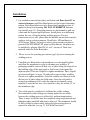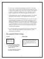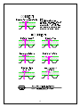
1
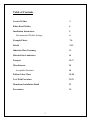
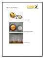
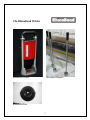
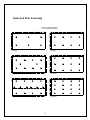
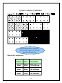
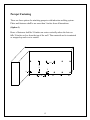
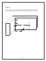
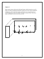
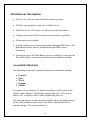
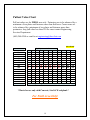
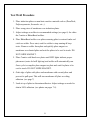
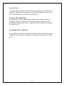
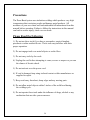
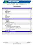
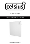
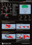
Duro-Bond®
Induction Welding System
User’s
Manual 2011
Duro-Last® Roofing, Inc.
525 Morley Drive
Saginaw, MI 48601
800-248-0280 Ph.
www.duro-last.com
The Duro-Bond® System
The Duro-Bond system is a mechanically-attached installation option for
installing thermoplastic membranes to substrates, without penetrating the
roofing system, using specially coated plates. The Duro-Bond system will
allow both Centrix® and RhinoBond® welders to be used to attach the DuroLast membrane to the induction plates.
The Duro-Bond system may ease the installation process by reducing some
installation steps. The insulation and membrane do not have to be
mechanically-attached in separate steps like traditional mechanicallyattached systems. The induction plates are used to secure the insulation. The
Duro-Last membrane is then welded to the surface of the installed induction
plate. The induction plates are installed in pre-determined patterns, and the
membrane is unrolled from carpet rolls, ready to begin the induction welding
process.
The use of carpet rolls and fewer fasteners may ultimately save time and
labor costs in the field.
All Duro-Last colors and warranties are available for this system. All DuroBond plates must be purchased through Duro-Last Roofing, Inc. to obtain
the warranty. Refer to the mechanically-attached specifications for all DuroBond projects.
Thank you for using the Duro-Bond system for your induction welding
needs. Please feel free to call the Duro-Last Engineering Services
Department with any comments or concerns in regards to this system.
Duro-Last Roofing, Inc.
1
Table of Contents
Centrix Welder
3
Rhino Bond Welder
4
Installation Instructions
5
Recommended Welder Settings
6
Example Photos
7-8
Details
9-12
Induction Plate Fastening
13
Material Size Limitations
14
Parapets
15-17
Miscellaneous
18
Acceptable Substrates
18
Pullout Value Chart
19-20
Test Weld Procedure
21-22
Membrane Installation Detail
23
Precautions
24
2
The Centrix Welder
Centrix Welder
Centrix Magnet & Plate
Installed Pattern
3
The RhinoBond Welder
RhinoBond Welder
RhinoBond Magnets
RhinoBond Plate
4
Installation
1. Lay insulation material into place and fasten with Duro-Last #15 or
concrete fasteners and Duro-Bond plates per the required fastening
pattern. Duro-Bond plates are to be driven until enough pressure is
applied to keep from spinning. DO NOT OVERDRIVE fasteners
(see detail 4 page 12). Fastening patterns are determined by pull test
values and the required uplift pressure. Install plates in a uniformed
pattern for ease of locating during welding process. For new
construction or tear offs, plates must be installed on non-heat sensitive
surfaces such as polyisocyanurate, DensDeck®, SP Insulfoam® or
ACH Secure Therm®. On projects where a heat sensitive product is
present (EPS/XPS,EPDM, DL approved Slip Sheets), the plates can
be installed by placing Atlas FR-10® or 4” cutouts of Duro-Last
material under the Duro-Bond plate.
2. Please review the operating precautions (pg.24) prior to starting the
welding process.
3. Unroll the pre-fabricated no tab membrane over the installed plates
and allow the membrane to relax to eliminate any wrinkles. If
packaging wrinkles exist weld first row of plates along the long side at
the building edge of the start panel or field seam of start panel for
adjacent panel. Then use Gripull® to tighten membrane. Place Gripull
(as shown in Figure A on pg. 24) and pull to remove large wrinkles.
Do not over tighten membrane. Once the wrinkles are removed weld
the last row of plates along the field seam. Once the roof panel is
secured on minimum of two sides the adjacent roof panels can be
installed. Locate the last row of roof panels so they are within 12” of
the membrane edge.
4. Test welds must be completed to calibrate the welder settings.
Recommended welder settings are starting points for test welds
because the welding process is affected by ambient temperatures.
Three or more test welds must be completed using scrap material and
induction plates until full adhesion is achieved. The membrane should
be fully welded to plate surface and peeled down using pliers to
expose the adhesion. (see pg. 21 Test Weld Procedure)
5
5. Locate plates by rubbing the membrane with the sole of your shoe.
Center welder over plate. DO NOT MOVE welder during cycle: this
will cause bad or partial welds. Once weld is complete place magnets
on plate to finalize the bonding process. Once all supplied magnets
have been applied then re-use the first magnet and repeat cycle.
6. All Duro-Bond plates must be mechanically attached to the substrate
and welded to the membrane. 100% adhesion must be achieved.
7. Welds can be tested after Duro-Bond plates have cooled to the touch
by placing approved plunger next to the plate and lifting up on the
plunger. A bonded plate will create a crease in the membrane; an unbonded plate will have membrane lift up from plate. Mark any partial
or un-bonded plate & return when cool to touch to re-weld. If 100%
adhesion is not achieved on second weld attempt then replace plate,
weld and patch membrane.
8. It is very important to keep magnets clean from metal shavings and
debris. Clean off magnets and roof sections regularly to avoid
embedment into membrane.
Recommended Welder Settings
Centrix
Rhino Bond
40 mil = 4.2 sec
50 mil = 4.2sec
60 mil = 4.4 sec
The energy level must be adjusted up
(+1, +2, etc.) when temperatures are
below 70 degrees F, and down (-1,-2,
etc.) when temperatures are above 70
degrees F.
Note: If 100% adhesion is not achieved
then adjust welder settings by 0.2
sec. up or down until optimum
setting is achieved
** See welder manufacturer operation
manual for welder adjustments
6
Examples
Test Pull
Partial Weld
7
Excessive Heat (Bad Weld)
Good Weld (100% Adhesion)
8
Details
1
9
2
10
3
4
11
5
© COPYRIGHT 2009
12
Induction Plate Fastening
Induction Plate Fastening
4' x 8' Insulation Boards
6 Plates
8 Plates
10 Plates
12 Plates
14 Plates
16 Plates
13
Typical insulation installation
All warranted projects must have
induction plates purchased through
Duro-Last Roofing, Inc.
Material Limitations
Material
Sq.Ft.
Carpet Rolls
40 mil
2,500
100' x 25' max.
50 mil
2,000
80' x 25' max.
60 mil
1,500
60' x 25' max.
14
Parapet Fastening
There are three options for attaching parapets with induction welding system.
Plates and fasteners shall be no more than 3-inches from all transitions.
(Option 1)
Rows of fasteners shall be 24-inches on center vertically unless the last row
falls 30-inches or less from the top of the wall. Then material can be terminated
or wrapped up and over to outside.
49
26789
167A9
49
167A9
15
(Option 2)
16789
Deck membrane run up the wall can be fastened 5-foot on center horizontally
and 12-inches on center vertically with base flashing at 30-inches on center.
B6789
49
49
267A9
16
(Option 3)
When using separate roll good to flash wall, plates shall be spaced in rows 24inches on center vertically and fastened 18-inches on center. If deck membrane
is flashed up wall 6–inches then plates and fasteners are required at base of
wall. Roll goods must be tack welded 18-inches on center at base. Duro-Last
square metal plates can be used at base of wall.
26789
167A9
49
49
167A9
17
Miscellaneous Information
1 Two way air vents are required with the induction system.
1 All Duro-Last membrane colors are available for use.
1 Only Duro-Last # 15 Fasteners are allowed for plate attachment.
1 Ordering material in 4-foot increments when possible is preferred.
1 All warranties are available.
1 Centrix welders can be rented and purchased through FRS Centrix. The
RhinoBond welders must be purchased through OMG or their
distributors.
1 Training for use of the Duro-Bond system is available by contacting the
Duro-Last Quality Assurance department and scheduling a training.
Acceptable Substrates
The following are the only acceptable substrates for induction welding.
1
1
1
1
1
Concrete
Steel
Wood
Gypsum
Purlins
Acceptance of any substrate for induction welding is solely based on the
pullout values obtained. All buildings in high wind zones 110 m.p.h. or
above or 40’ in height or taller contact Engineering Services.
The fastening patterns are determined by pullout values and uplift pressure
for the field, perimeters and corners. (See Mech. Attached Duro-Last
specification pg. 5 for required pull tests.)
18
Pullout Value Chart
Pull out values are for FIELD area only. Perimeters are to be enhanced by a
minimum of two plates and fasteners more than field area. Corner areas are
to be enhanced by a minimum of two plates and fasteners more than
perimeters. Any pull value less than 210 lbs. must contact Engineering
Services Department.
(800) 248-0280 or email us at [email protected]
40 & 50 mil
Uplift pressure in lbs.
Pullout Values
60
550 +
525
500
475
450
425
400
375
350
325
300
275
250
225
210
Less than 210
75
90
105
120
6
8
8
10
10
6
8
8
10
10
6
8
8
10
10
6
8
8
10
10
6
8
8
10
10
6
8
8
10
10
6
8
8
10
10
6
8
8
10
12
6
8
8
10
12
8
8
10
12
12
8
10
10
14
14
8
10
12
14
14
8
10
12
16
16
10
12
14
16
n/a
10
12
14
16
n/a
Contact Engineering Services
135
150
165
180
12
12
12
12
12
12
12
12
14
16
16
16
n/a
n/a
n/a
14
14
14
14
14
14
14
14
14
16
16
n/a
n/a
n/a
n/a
16
16
16
16
16
16
16
16
n/a
n/a
n/a
n/a
n/a
n/a
n/a
n/a
n/a
n/a
n/a
n/a
n/a
n/a
n/a
n/a
n/a
n/a
n/a
n/a
n/a
n/a
195
n/a
n/a
n/a
n/a
n/a
n/a
n/a
n/a
n/a
n/a
n/a
n/a
n/a
n/a
n/a
*Charts for use only with Concrete, Steel & Wood plank *
For Field Area Only!
19
210
n/a
n/a
n/a
n/a
n/a
n/a
n/a
n/a
n/a
n/a
n/a
n/a
n/a
n/a
n/a
60 mil
Uplift pressure in lbs.
Pullout Values
60
550 +
525
500
475
450
425
400
375
350
325
300
275
250
225
210
Less Than 210
75
90
105
120
6
6
8
8
10
6
6
8
8
10
6
6
8
8
10
6
6
8
8
10
6
6
8
8
10
6
8
8
10
10
6
8
8
10
12
6
8
10
10
12
6
8
10
12
12
8
10
12
12
12
8
10
12
14
14
8
12
12
14
14
10
12
12
14
16
10
12
14
16
n/a
12
14
14
16
n/a
Contact Engineering Services
135
150
165
180
195
210
10
10
10
10
10
12
12
12
14
14
16
16
n/a
n/a
n/a
12
12
12
12
12
12
14
14
14
16
16
n/a
n/a
n/a
n/a
12
12
12
12
14
14
14
16
16
n/a
n/a
n/a
n/a
n/a
n/a
14
14
14
14
14
16
16
16
n/a
n/a
n/a
n/a
n/a
n/a
n/a
14
14
14
14
16
16
16
n/a
n/a
n/a
n/a
n/a
n/a
n/a
n/a
16
16
16
16
16
16
n/a
n/a
n/a
n/a
n/a
n/a
n/a
n/a
n/a
*Charts for use only with Concrete, Steel & Wood plank*
For Field Area Only!
20
Test Weld Procedure
1. Place induction plates on non-heat sensitive material such as (DensDeck,
Polyisocyanurate, Securock® etc..,).
2. Place scrap piece of membrane over induction plates.
3. Adjust settings on welder to recommended settings (see page 6) for either
the Centrix or RhinoBond welders.
4. Place RhinoBond welder over plates ensuring plate is centered under red
circle on welder. Press start, wait for welder to stop running & beep
twice. Remove welder from plate and quickly place magnet on
membrane over heated plate and wait for plates to be cool to touch. DO
NOT SLIDE MAGNET.
5. Place Centrix weld head over plates until LED lights indicate proper
placement (center led will light up) and welder will automatically run.
Once cycle is complete place magnet on plate and wait for plates to be
cool to touch. DO NOT SLIDE MAGNET.
6. Grab edge of plate with pliers and membrane with second pliers and
proceed to pull apart. This will tear membrane off plate revealing
adhesion. (see page 7)
7. Look at top of plate to determine adhesion. Adjust settings as needed to
obtain 100% adhesion. (see photos on pages 7-8)
21
Partial Weld
Top of the plate is partially exposed. No burn marks present. Welder time
should be adjusted up and another test performed following steps 1 thru 7
until 100% adhesion is obtained. (see photo pg. 7)
Excessive Heat (Bad Weld)
A partial weld or fully exposed plate. Black or burn marks on plate or
membrane. Welder settings must be adjusted down and another weld
performed following step 1 thru 7, repeat until 100% adhesion is obtained.
(see photo pg. 8)
Good Weld (100% Adhesion)
Proper adhesion is achieved with bottom film on plate & exposed scrim on
underside of test samples. Installation of membrane can begin. (see photo
pg. 8)
22
0F!
FD010
(E)E*)
%D)E+,-.
/)E
)F)
E
$
!
3+*D0
,)E+.
56789
!
286789
1
$
!
$
!
$
2
286789
CDEFD
A7D
&F7D'E
2F&D
!"#D
$"!%DD
23
Precautions
The Duro-Bond system uses induction welding which produces very high
temperatures that can injure people and damage metal products. All
members of your crew must read and understand all instructions from this
manual before operating. Failure to follow the instructions in this manual
can lead to serious injury, shock or even death.
Please Read the Following
1). Do not use these tools if you have a pacemaker, surgical implant,
prosthesis or other medical device. These tools may interfere with their
proper operation.
2). Do not engage tools over metal objects or on the floor.
3). Do not carry tools by the cords.
4). Unplug the cord before attempting to clean, service or inspect or you risk
the chance of electric shock.
5). Do not activate over the power cord.
6). If cord is damaged stop using tool and contact welder manufacturer or
supplier for repair.
7). Keep cord away from heat, sharp edges and any moving parts.
8). Do not allow metal objects within 3-inches of the weld head during
the welding cycle.
9). Do not operate these tools under the influence of drugs, alcohol or any
medication that can alter your awareness.
24
25