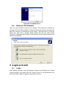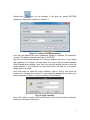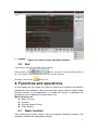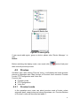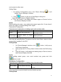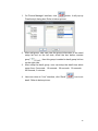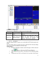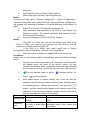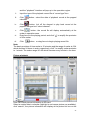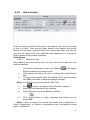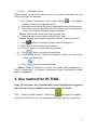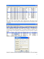
1
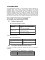
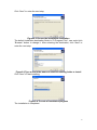
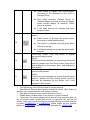
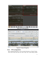
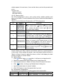
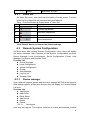
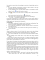
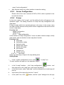
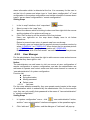
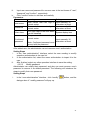
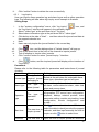
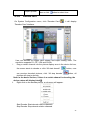
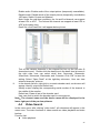
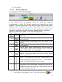
CMS USER’S MANUAL
2010-5-21
1
INDEX
INDEX ............................................................................................................................... 2
Preface.............................................................................................................................. 3
1. Introduction ................................................................................................................ 4
2. Install and uninstall CMS............................................................................................ 4
2.1
System requirement ........................................................................................ 4
2.2
Computer Hardware Requirements................................................................. 4
2.3
Process of Installation ..................................................................................... 5
2.4
Remove the Software...................................................................................... 7
3. Login and exit............................................................................................................. 7
3.1
Login ............................................................................................................... 7
3.2
Exit .................................................................................................................. 9
4. Functions and operations........................................................................................... 9
4.1
Basic function.................................................................................................. 9
4.1.1
Lock & Unlock..................................................................................... 10
4.1.2
Minimize & Maximize.......................................................................... 10
4.1.3
Alarm Display ..................................................................................... 10
4.1.4
Camera Display List ........................................................................... 10
4.2
Preview ..........................................................................................................11
4.2.1
Preview Locale ....................................................................................11
4.2.2
PTZ configuration ............................................................................... 14
4.2.3
Video Set ............................................................................................ 16
4.3
Remote System Configuration ...................................................................... 16
4.3.1
Device manager ................................................................................. 16
4.3.2
Local configuration ............................................................................. 22
4.3.3
Server Configuration........................................................................... 27
4.3.4
E-map................................................................................................. 27
4.3.5
User Manager..................................................................................... 30
4.3.6
Decode card ....................................................................................... 34
4.4
Video Search................................................................................................. 35
4.4.1
Video playback ................................................................................... 36
4.4.2
Video backup...................................................................................... 39
5. Use method for IP-TOOL ......................................................................................... 40
6. Troubleshooting ....................................................................................................... 44
2
Preface
Central management software (short for CMS below) is a typical client
management program whose main function is to centralize all devices together
and realize the unified management of parameters and authorization, which is
greatly improve the efficiency of control and operation to all embedded digital
video recorders and network video servers as well as software compressed
cards connected through the network.
This manual will help you to familiarize with the software and master its
operation methods.
Notice:
z As product update, the contents of this manual are subject to change
without notice.
z Some part functions and symbols may not be completely same with
what you get due to the continuous revision of this software.
3
1. Introduction
Central Management Software is a client procedure designed especially for
embedded digital video recorders, network video servers and software
compressed cards to realize remote centralized management. In the video
surveillance system, the administrator can control video input devices and
conduct all possible rights such as setting up cameras, PTZ, etc through
configuring parameters, viewing the live site to achieve the purpose of live site
surveillance, video record and record file backup and so on. It possesses three
main functions: preview the live site, system configuration and video search,
which will be presented specifically in the third function part.
2. Install and uninstall CMS
2.1
System requirement
z Supported Operating System:
Operating system
Windows XP
Windows 2000
Windows Vista
Comments
Windows XP SP2 or most updated
patch,
Direct 9.0c or the higher
Windows 2000 SP4,
Direct 9.0c or the higher
Windows Vista
Direct 10.0c or the higher
Note: Windows 2003 series.
z Supported Browser
Operating system
Microsoft Internet Explorer
v6.0
Microsoft Internet Explorer
v7.0,
2.2
Comments
IE 6.0 with most updated service
pack
IE 7.0 with most updated service
pack
Computer Hardware Requirements
To ensure the software running well, please make sure the computer is
compatible.
z Recommended PC Specification – 4 channels
Item
CPU
Memory
Specification
Intel Pentium 3.0 GHz or AMD 3000+
1GB
4
HDD
160GB
z Recommended PC Specification -8 channels:
Item
CPU
Memory
HDD
Specification
Intel Core 2 Duo 1.8 GHz or AMD Dual
core 3800+
1GB
250GB
z Recommended PC Specification -16 channels:
Item
CPU
Memory
HDD
Specification
Intel Core 2 Duo 2.2 GHz or AMD Dual core
3800+
2GB
250GB
Note:
z The upper recommended specification aims at CIF real-time
resolution.
z The AMD chip hyper-3800+ and X64 series are not tested;
z If user wants to have real-time live view with CIF resolution, the max
connection number is 16 in one computer according to the current
capacity;
z If user wants to have real-time live view with D1 resolution, the max
connection number is 4 in one computer.
2.3
Process of Installation
a) Before to install central management software in your computer,
please make sure all the anti-virus software in your computer closed so
that the control center program can install correctly in your computer. In
addition, the setting of your IE browser must enable the download of
activeX control.
b) Run the “Control Center” from software CD, the next menu will pop
up;
Figure2-1 Welcome menu
5
Click “Next” to enter the next step;
Figure2-2 Choose the installation destination
The default installation destination folder is “C:\Program Files”, user could click
“Browser” button to change it. After selecting the destination, click “Next” to
enter the next step.
Figure2-3 Type a new folder name or select an existing folder to install
Click “Next” to start installing;
Figure2-4 The rate of installation progress
The installation is completed.
6
Figure2-5 Completed menu
2.4
Remove the Software
There are two methods to remove the software. One method to uninstall the
software is like all other software. Users shall enter the removal interface and
then click 'remove" to uninstall this control center. The other way is to click the
setup icon, and then a window shown below will pop up, users select
"Remove" to dismantle this software. After Removed, the computer system will
reboot automatically.
3. Login and exit
3.1
Login
After building Network Video Surveillance System and installing the Control
Center program, user need login the Control Center to set parameters and
watch the locale. Steps of login are described as below:
7
Double-click
icon on the desktop, it will pop up 'create SYSTEM
password ' dialog box, referred to Figure3-1.
Figure 3-1 create SYSTEM password
User can self-defined the user’s password, letters or numbers, 32 characters
at most. The default original username is SYSTEM.
Input the correct Email address in the server address text box, If user forget
the password, the system will auto send it to user’s defined email address;
After finished above setting, click “test your account settings” button to test the
email address, if the networks is connected, there will pop up a “success”
dialog, and vice versa.
Click OK button to enter the Login interface, refer to Fig3-2, and input the
password in the password text box. If user forget the password, can press “get
system password” button to get it according to the direction.
Fig 3-2 login interface
Click 'OK' button to enter the Control Center. The Control Center Operation
Interface is shown as Figure3-3.
8
Figure 3-3 Control Center Operation Interface
3.2
Exit
There are two ways to exit control center normally.
Firstly, please click
button, and then an inquiry dialogue will pop
up. If you confirm to exit, please click "yes", the system will close.
Secondly, user can click
button to exit.
4. Functions and operations
In this chapter we will divide four parts to instruct the functions and specific
operations of this software. Users can enter the control center to watch locale
through Internet, to set parameters, to enable the record, to playback the
record files, and to backup the record and so on.
Main Function List:
z Basic Function
z Preview
z Remote System Config
z Video Search
4.1
Basic function
After entering the Control Center, users can operate following functions. The
operation methods are described as below:
9
4.1.1
Lock & Unlock
'Lock & Unlock' button.
expresses the Operation Interface is on 'Unlock' status.
expresses
the Operation Interface is on 'Lock' status.
User could lock current operation interface. When current operation interface is
on 'Lock' status and user need to operate the Control Center, he needs input
username and password on 'Login' dialog box to unlock the Control Center
Operation Interface. The Control Center Operation Interface which user could
operate is on 'Unlock' status.
4.1.2
Click
Minimize & Maximize
to maximize 'Control Center' window. Click
to minimize
'Control Center' window or revert the 'Control Center' to original size.
4.1.3
Alarm Display
In the alarm display item, all the alarm information will be displayed. It mainly
includes: Alarm Type, Device Name, Camera Number and Alarm Time as well
as video lose, motion and so on. Alarm Display List is shown as Figure4-1.
Figure4-1 Alarm Display List
4.1.4
Camera Display List
Camera Display List is used to display all devices added. User may Click
'Device List' or 'Camera Group' page to switch display mode.
Figure4-2 displayed the DVS aligned according device list. User may drag
device in the Device List to Operation area for watching the locale. Figure3
displayed the DVS aligned according camera list. User may drag the group to
Operation area for watching all camera of this group.
10
Figure4-2 Device list
Figure4-3 Camera group
If user needs add region, group or device, please refer 'Device Manager ' to
add.
Notice:
Before switching the display mode, user needs click
button firstly and
then close all preview pictures.
4.2
Preview
On Menu area, after clicking 'Preview' menu, it will display the locale preview
picture on Operation area. Main function of 'Preview' menu contents: Preview
Locale, PTZ Configuration and Video Set.
Function List:
z Preview Locale
z PTZ Configuration
z Video Set
4.2.1
Preview Locale
In the operation area, users can select preview mode of locale, select
automatic dwell, snap picture and close all previews, etc. Function Buttons
of Preview Locale are described as table4-1.
11
Table1 Function Buttons & Explanation of Preview Locale
No.
Buttons
Meanings
1
Single Picture Preview' button. Click this button to
watch every camera in single picture preview mode.
2
'4 Picture Preview' button. Click this button to watch
every camera in four picture preview mode.
3
'9 Picture Preview' button. Click this button to watch
every camera in 9-picture preview mode.
4
5
6
7
8
8
9
'16 Picture Preview' button. Click this button to watch
every camera in 16-picture preview mode.
25 Picture Preview' button. Click this button to watch
every camera in 25-picture preview mode.
'36 Picture Preview' button. Click this button to watch
every camera in 36-picture preview mode.
Click this button to select 6-picture
6-picture
preview
Click this button to select 8-picture
8-picture
preview
Click this button to select 13-picture
13-picture
preview
Click this button to select 49-picture
49-picture
preview
Click this button to select 64-picture
64-picture
preview
Turn on sound button, click this button to turn on
audio signal
'Snap' button. Click this button to snap locale picture
of one camera you select. User could snap 10
pictures once at best. Click 'Snap' button to pop up a
dialog, referred Figure2.
'Close All Preview' button. Click this button to close
current locale picture and stop preview. Before
switching display mode, user must close all previews
first.
'Dwell' button. Range of selecting to dwell is from
single picture preview mode to 9 picture preview
mode.
Notice:
12
z
Dwell means to display every locale picture
according to the sequence of the DVS in
Camera Group.
z
Only when selecting 'Camera Group' on
Camera Display List area and current display
mode couldn't display all cameras, 'Dwell'
button is enabled.
z
It will dwell among the cameras that have
locale pictures.
'Dwell Group' button.
Notice:
10
z
Dwell means to preview the group picture
according to setup camera group
z
This button is available only the group dwell
function is set up
z
It will dwell among the groups that have locale
pictures.
'Pre-Group' button. Click this button to display
pre-group locale pictures.
Notice:
10
If there are some cameras not connecting with locale
pictures, please click 'Pre Group' button, they will be
also displayed on the screen, but it only displays in
blue screen.
'Next Group' button. Click this button to display next
group locale pictures.
Notice:
If there are some cameras not connecting with locale
11
pictures, please click 'Next Group' button, and they
will also be displayed on the screen, but it only
displays in blue screen.
Users can right-click on the live preview picture to do below operation:
•
Turn off the live: turn off live picture of current channel
•
Start Manual Record: start current channel to record. After close live
preview, the manual record of this channel will stop.
•
Stop Manual Record: stop current channel to record.
•
Enable audio: Enable audio of live picture of current channel
•
Full screen: Full screen display all live picture in the operation area. At
the full screen mode, double-click mouse or right-click can exit the full
screen mode; user can output the live preview pictures to another monitor
by select \\.\DISPLAY1 or \\.\DISPLAY2. When output the live preview
picture to \\.\DISPLAY1, user can do other operation on \\.\DISPLAY2.
13
Figure 4-4 Camera preview
Figure4-5 “Snap” Dialog Box
4.2.2
PTZ configuration
After connected with dome, user can control the dome on Control Center.
User could control the dome up, down, right, left or stop rotating, adjust
14
rotation speed, Iris and zoom, focus on the dome, and set the presets and
so on...
Function List:
z Dome Control
z Preset Setting
4.2.2.1. Dome control
On 'PTZ Configuration' menu, user could control rotation position and
speed of the dome. Function buttons of the Dome Control are described as
Table4-2
Table1 Function Buttons & Explanation of PTZ Configuration
No.
Buttons
Meanings
means the dome rotate up.
means the
dome rotate down. means the dome rotate
1
left. means the dome rotate right. means
the dome stop rotating.
Drag the bar to adjust rotating speed of the
2
dome.
'Iris' button. Click
button near 'Iris' button to
3
increase light of the dome. Click
button
near 'Iris' button to decrease light of the dome.
'Zoom' button. Click
button near 'Zoom'
button to zoom in the locale picture of this
4
camera. Click
button near 'Zoom' button to
zoom out the locale picture of this camera.
'Focus' button. Click
button near 'Focus'
5
button to have long focus. Click
button near
'Focus' button
4.2.2.2. Preset setting
Preset means user sets a camera surveillance point for a special position
of the locale. When setting the preset, user may adopt function buttons in
Table1 of Dome Control to adjust the dome, so that it will display the best
picture of locale on Control Center.
z Setting Steps
i. Click
button in
item, it will pop up a drag-down list.
ii. Select the preset which user wants to set in drag-down list.
iii. Use function buttons in Table1 of Dome Control to adjust the dome.
iv. Click
button, it will pop up 'Modify Name' dialog box.
v. Input the preset name in 'preset' textbox.
vi. Click 'OK' button to save the preset which you set.
z Parameters Configuration
Parameters and explanation of setting preset refer below table.
Parameters Meaning
How to Set...
preset
Name of the Input manually. It could input
11
15
preset.
4.2.3
characters at most.
Video Set
On Video Set menu, user could set the quality of locale picture. Function
buttons of the Video Set are described as belowTable4-3.
Table 1 Function Buttons & Explanations of Video Set
No. Buttons
Meanings
1
Brightness adjustment
2
Contrast adjustment
3
Saturation adjustment
4
Hue adjustment
5
Sound adjustment
Notice:
Click 'Default' button to resume the default settings.
4.3
Remote System Configuration
On Menu area, after clicking 'System Configuration' menu, there will display
the entire submenu. Main function of the System Configuration contents:
Device Manager, Local Configuration, Server Configuration, E-map, User
Manager, Log Inquiry and Decoder Card.
Function List
z Device Manager
z Local Configuration
z Server Configuration
z E-map
z User Manager
z Log Inquiry
z Decoder Card
4.3.1
Device manager
User could add regions, groups and devices to manage all DVS in the network.
After adding regions, groups and devices, they will display on Camera Display
List area
Function List
z Add Region
z Add Group
z Dwell Setup
z Add Device
z Modify
z Delete
4.3.1.1
Add region
User may set regions. The regions could be an indoor environment, outdoor
16
environment or other area.
Setting Steps:
i. On System Configuration menu, click 'Device Manager’
display 'Device Manager' interface.
, it will
button, it will pop up 'Add Region' dialog box.
ii. Click
Input the region name in 'Region' textbox.
iii. Click 'OK' button, it will display the added region on Device List box
and Camera Display List area.
Notice
Before adding sub region, user needs select parent region first. If user doesn't
select any region, it means adding senior region.
Parameters Configuration
Parameters and explanation of adding region refer to below table.
Parameters
Meanings
How to Set...
Region
Region name of the DVS.
Input manually. It can input 32
characters at most.
Parent Region
Superior
region.
Display parameter.
region
of
current
4.3.1.2
Add group
User may set camera group. The group could be some floors, rooms or other
groups which installed in the DVS.
Setting Steps
i.
ii.
iii.
button, it will pop up
On 'Device Manager' interface, click
'Add Group' dialog box.
Input group name in 'Group Name' textbox which the DVS belong
to.
Click 'OK' button, it will display the added group on Device List box
and Camera Display List area.
Notice
When adding parent group, user must unselect any group and click
button to add.
Parameters Configuration
Parameters and explanation of adding group refer below table.
Parameters
Meanings
How to Set...
Group Name
Group name of the DVS.
Input manually. It will input 32 characters
at most.
4.3.1.3
Dwell Setup
User can setup the preview dwell function between groups.
Setting Steps
17
1. On 'Device Manager' interface, click
button, it will pop up
'Dwell setup' dialog box. Refer to below picture:
2. After add group, user can view the group information in the dwell
setup list box on the left side; check the box before camera
group
, then this group is added to dwell group list box
on the right side .
3. After setup the dwell group, user can setup the dwell time which
range from: 5 seconds,10 seconds,20 seconds,30 seconds,
60 seconds, 2 minutes.
4. User can return to “Live” interface, click “Dwell”
icon to do
dwell. Refer to below picture:
18
Parameters Configuration
Parameters and explanation of adding group refer below table.
Parameters
Meanings
How to Set...
Group name of the Input manually. It will input 32 characters
Group Name
DVS.
at most.
Double-click the “dwell time” user can
Dwell interval time select the dwell interval time range
Dwell Time
between groups
from:5 seconds, 20 seconds , 30
seconds,60 seconds, 2 minutes.
4.3.1.4
Add device
Only after adding region or group, user could add the DVS below region and
group.
User may select region or group every time to add the DVS. We take adding
device in the region as example to describe steps.
Setting Steps
i.
On 'Device Manager' interface, select the region in Device List and
ii.
iii.
click
button; it will pop up 'Add Device' dialog box.
Click 'Search Device' button, it will pop up 'DVS searching' dialog
box.
Double-click the DVS in left device list to go back 'Add Device'
19
dialog box.
iv.
Input the DVS name in 'Device Name' textbox.
v.
Select data type in 'Bit rate Type' drag-down list.
Notice
User may set data type in 'System Configuration -> Server Configuration->
Camera Configuration' after adding the DVS, referred Channel Configuration'.
We suggest user selecting first stream in LAN and selecting "small stream" in
WAN.
vi.
Select IP of the DVS in 'IP Address' drag-down list.
vii.
Input username and password of the DVS in 'User Name' and
'Password' textbox. The default username and password of the
DVS are admin and admin.
viii.
Input the visiting port of the DVS in 'Port' textbox.
Notice
•
If the DVS is in LAN, user may use the default port: 9008. If the
DVS is in WAN, user need set only one port for every DVS so that the
computer in network could visit the DVS.
•
If the DVS is in WAN, user could modify port in 'Server
Configuration->Net Configuration', referred ' Net Configuration '.
ix.
Click 'OK' button to display the added DVS in the Device List.
Parameters
Please refer to the following table for parameters and instructions of adding
device.
i.
For the device added successfully, all channels it connecting with
will display under the name of the device. Herein, we only
introduce the network video surveillance server with single channel,
thus the server can only connect with the one video input terminal.
ii.
This icon denotes region or group;
server;
iii.
it denotes device, viz.
it denotes channel
After added device to "device edition" box, users can add the
channel in the device to the relative channel group, and then select
the channel group in" channel group edition" box and click
button,and the channel will be added in the channel group. If the
channel is in the recycling condition, please close live preview at
first and then add the channel to the group.
Parameters
Meanings
How to set
The name of the Input manually, 32 characters at
Device name
device
most
Net transmission type Select at the pull-down list,
Streaming
of video & audio data selectable items: main stream and
type
of server
sub-stream.
20
IP address of the After searched device, select at the
server
pull-down list.
Name of the region
Region name
System display item
where the device is
User name to visit Input manually, 19 characters at
User name
server
most.
Password
to
visit
Password
input manually, 19 characters at most
server
Server
Port number to visit Input manually, 32 characters at
terminal
server
most.
4.3.1.5
Modify
Users can modify region names, group names, device names and channel
names.
Setting Steps
i.
Modify Region
IP address
z
z
z
z
z
z
z
z
z
In camera group list, select the group and click
'Modify Group Info' dialog box.
Input new group name in 'Group Name' textbox.
Click 'OK' button to modify the group name.
ii.
Modify Group
button, it will pop up
In camera group list, select the group and click
'Modify Group Info' dialog box.
Input new group name in 'Group Name' textbox.
Click 'OK' button to modify the group name.
iii.
Modify Device
button, it will pop up
In device list, select the device and click
'Modify Device Info' dialog box.
Input new device name in 'Device Name' textbox.
Click 'OK' button to modify the device name.
iv.
Modify Channel
button, it will pop up
z
In device list, select group name and click
button, it will pop up
'Modify Channel Info' dialog box.
z Input new channel name in 'Channel Name' textbox.
z Click 'OK' button to modify channel name.
Parameters Configuration
Parameters and explanations to modify region names, group names, device
names and channel names refer to table below.
Parameters
Meanings
Modify region name
Setup
21
Region name
Superior region
Group name
Device name
Name of the region where
monitor points are
Parent region name
Modify group name
Name of the group where
monitor points are
Modify name
Name of the device
Channel name
Net transmission type of video
& audio data
IP address of the server
Name of the region where the
device is
User name of the server to
visit
password of the server to visit
Terminal number of the server
to visit
Modify channel name
Channel number in the device
Channel name
Channel name in the device
Stream type
IP address
Region name
User name
Password
Terminal server
Input
manually,
32characters at most
System display item
Input
manually,
characters at most
32
Input
manually,
characters at most
32
System display item
System display item
System display item
System display item
System display item
System display item
System display item
Input
manually,
32characters at most
4.3.1.6
delete
Users can delete region, group, device and channel.
Setting Steps
i.
Select the region, the group, the device or the channel needing to
be deleted.
ii.
iii.
4.3.2
Click
button, pop up "confirm" dialogue box
Click “yes” button to delete this item
Local configuration
In the system configuration interface, after clicking “local configuration"
submenu, in the operation area all setting tags will pop up. The setting
functions of local configuration are: local basic configuration, local schedule
configuration and local alarm configuration.
Function List
z Local basic configuration
z Local schedule configuration
z Local alarm configuration
4.3.2.1.
Local basic configuration
22
In the “local basic configuration" interface, users can set live configuration,
record configuration, local alarm configuration, log list maintain, other
configuration, PC restart configuration and version information.
Setting Steps
i
In the “system configuration" menu, click "local configuration” icon.
ii
The “local configuration" will pop up in the operation area.
iii
Select “local basic configuration" tag, and the “local basic configuration"
interface will appear.
iv
In " preview setting" box, set display time and headline display mode of the
channel at recycle play
v
In the "video setting" box, set whether to do record recycle and set save
path of video files.
vi
In the "server alarm configuration" box, set alarm holding time for each
alarm and post-alarm record time.
vii
In the "maintenance of journal" box, set periods to save alarm journal and
operation journal.
viii
In the “other configuration “box, set picture numbers being cut for each
time, save path to store copy files and control center time.
Note:
Users can set control center time by themselves, or select the time
synchronous with the computer
ix
In the “PC restart configuration “box, input user name and password of the
23
PC, the interval by day and date and tick off the “PC Auto Restart”, the
device will auto restart according to setups.
x
After finished, select any other operation interface to save the setting.
Parameters
Please refer to the following table for parameters and instructions of local basic
configuration.
Parameters
Meanings
Settings
Live configuration
Select at the drag-down list,
set the holding time in one selectable items 5s、10s、
dwell time
picture at recycle play
15s、20s、30s、40s、50s and
1min.
Set live picture numbers Select at the drag-down list,
Snap
picture
being cut each time for users can set up to photo
numbers
single channel
1--30 pictures
select at the drag-down list,
Channel
and
device
selectable
items:
none,
Title
information displayed on
channel name and device
the top of live pictures
name +channel name
Record configuration
To set whether to continue
recording to cover the
Recycle
Tick off the check box in the
earliest video file when the
recording
front of " recycle record"
disc storing video files is
full.
set save path of video files,
Tick off the check box in the
Record partition
users can set many a discs
front of the disc.
to save video files
Local alarm configuration
Select at the drag-down list,
Alarm
holding .Alarm holding time after
selectable items 10s、20s、
time
being triggered
30s、40s、1min. and 2min.
Select at the drag-down list,
Post-alarm
Recording time after alarm selectable items:10s、20s、
Record time
being triggered
30s、1min.、2min.、5min and
10min.
Log
list
maintenance
Select at the drag-down list,
Alarm log list set periods to save alarm selectable items : within one
save
journal
week, within half a month
and within one month
Save time of Set periods to save Select at the drag-down list,
operation journal operation journal
selectable items: within one
24
week, within half a month
Other configuration
Set live picture numbers
Serial port
being cut each time for Select at the drag-down list
single channel
Set the value according to Select the value at the
Baud Rate
the setting of speed dome drag-down list
Users
can
input
manually( must 14 numbers)
Time
Set control center time
and also may select the time
synchronous with computer
( click " rectify" to realize)
PC Restart Configuration
User Name
User name of PC
User can input manually
Password
Password of PC
User can input manually
Per day
The restart interval by day User can input manually
Restart time
The restart interval by time User can input manually
Version information
Display software version
software version number in the control System display item
center
4.3.2.2.
Local schedule configuration
Schedule record refers to the system to record according to the fixed record
time of single channel. In “local schedule configuration" interface, users can
set record periods of every week and record periods in special days, viz. week
schedule and day schedule.
Setting Steps
4.3.2.2.1
Week Schedule Configuration
User could set the record time from Monday to Sunday for recording everyday
in one week.
i
On 'Local Configuration' interface, select 'Local Schedule Configuration'
page, it will display 'Local Schedule Configuration' interface.
ii
In device list of left Operation area, select camera to set week schedule,
and click
iii
button.
On 'Week Schedule' item, drag the mouse to the weekday, and drag to
select the time when there is
in blank area.
Notice
Ruler
means 24 hour in one day, the lest graduation is 15 minutes.
After setting, user could select other interface to save the settings.
4.3.2.2.2
Day Schedule Configuration
25
User could set record time for recording in some time of special day, such as
holiday.
i
On 'Local Schedule Configuration' interface, select camera to set day
schedule in device list of left Operation area.
ii
On 'Day Schedule' item, input date which needs to set schedule in 'date'
textbox, or click
near 'date' textbox to select.
iii
Click
button, move the mouse to 'Holiday' item in 'Date Schedule'
item, drag to select time when there is
in blank area.
iv
After setting, user could select other interface to save the settings.
4.3.2.2.3
Local alarm configuration
Local alarm configuration is a kind of alarm mode of control center which is
triggered by alarm after alarm input device (such as motion detection sensor,
infrared sensor etc.) detects alarm information.
Setting Steps
i
In the “local configuration" interface, select” local alarm configuration" tag,
and the" local alarm configuration" interface will pop up.
ii
In the “local alarm configuration" interface, select a channel in one server
in the left device list.
iii
In the “alarm type” list, click to select one alarm type of the channel, e.g.
“motion detection".
Note:
When to select a server in the left device list, users can do alarm linkage
configuration to select the sensor connecting with device in “alarm type ".
iv
In the “alarm linkage type" list, tick off alarm linkage type needing to trigger.
Note:
z alarm linkage mode: sound alarm, e-map alarm and linkage channel
record
Sound alarm is control center sound "di, di" in which is triggered by alarm
information when the sensor detects alarm. Sound alarm can be triggered by
sensor alarm, motion detection or video loss.
E-map alarm is that alarm information triggers the alarm input device which is
opposite to the scene in the e-map to alarm by blinking. After setting alarm link
of alarm information and e-map alarm, users should set the relative camera of
alarm link in the e-map and map configuration. For further details, please refer
to chapter “set camera”
Linkage channel record is that alarm information triggers the channel to record
when the sensor detects alarm. After setting up linkage channel record, if users
need to modify alarm time and record time, please refer to "local basic
configuration" to modify. Linkage record alarm may be triggered by sensor
alarm or motion detection alarm.
z After set the mode of alarm, users need to set alarm input and relative
alarm output data in the “server alarm configuration" interface of the
26
menu” local configuration".
After finished, select any other interface to save the setting.
v
4.3.3
Server Configuration
Please refer to the user’s manual of DVR or DVS, which is packed in the
box with the device.
4.3.4
E-map
In the menu region, click "e-map", and the setting function will appear in the
operation region. The setting functions of e-map are map configuration and
map alarm.
E-map is a plan which is to simulate pictures in the scene. In the e-map, users
can add or delete camera at the position which is opposite to the scene as well
as set e-map alarm.
Function List
z Map configuration
z Map alarm
4.3.4.1
Map configuration
In the interface of “map configuration", users can add or delete e-maps, modify
map names, and set whether to start map alarm function.
Functions List
z Add maps
z Add brother nodes
z Add sub nodes
z Modify map names
z Delete sub nodes
z Set camera
z Change icon
z Delete camera
4.3.4.1.1
Add maps
Users can add many e-maps in the map adding area.
Setting Steps
i.
In the " system configuration" menu, click
" e-map" icon
“E-map" interface will pop up in the operation region.
ii.
In the "e-map" interface ,click "map configuration"
button,and
iv.
then right-click in the "map" tree, quick menu will pop up.
In the quick menu, select "add map", and the dialogue box to add map will
pop up.
Input name of the map at the text box " name"
v.
In the “path" box, click
iii.
button, and the “open" dialogue box will pop
27
up.
Select the save path of e-map, and click "open" button to confirm path.
Click “confirm" button to add e-map in control center successfully.
4.3.4.1.2
Add brother nodes
Users can add e-maps which is parallel with the previous map.
Setting Steps
vi.
vii.
i.
In the " e-map" interface, click
“map configuration” button,and
iii.
then right-click the added map in "map" tree, the quick menu will pop up.
In the quick menu, please select "add brother nodes", a dialogue of "add
map" will pop up.
Input name of the map at the text box of “name".
iv.
In the "path" box ,click
ii.
v.
vi.
button, and the " open" dialogue will pop up.
i.
Select the path to save e-map, and click "open" button to confirm the path.
Click "confirm" button to add map in the map control center successfully.
4.3.4.1.3
Add sub nodes
Users can add sub nodes in the previous maps.
Setting Steps
In the “e-map” interface,click “map configuration”
button,and click
the added map in the" map" tree with the right key of the mouse, and a
quick menu will pop up.
ii.
In the quick menu, select “add sub node",” add map “dialogue will pop up.
iii.
Input the name of the map at the text box of "name"
button, " open" dialogue will pop up.
iv.
In the “path” box,click
v.
Select the path to save e-map and click “open" button to confirm the saving
path.
vi.
Click "confirm" button to add map in the map control center successfully.
4.3.4.1.4
Modify map names
Users can modify e-map names.
Setting Steps
i.
In the “e-map” interface,click “map configuration”
button,and then
right-click the added map in the " map" tree, and a quick menu will pop up.
ii.
In the quick menu, select "modify sub node names", the dialogue of
"modify map name" will pop up.
iii.
Input the name of the map at the text box of "name"
iv.
Click "confirm" button to modify the e-map name successfully.
4.3.4.1.5
Delete sub nodes
Users can delete e-maps.
28
Setting Steps
i.
In the “e-map” interface,click “map configuration”
button.
ii.
In the “map" tree, select the map needing to delete and then right-click, a
quick menu will pop up.
iii.
In the quick menu, select “delete node", the "confirm" dialogue will pop up.
iv.
Click "yes" button to delete the map.
4.3.4.1.6
Set camera
Users can set a camera in the e-map where is opposite to the live.
Setting Steps
i.
In the “e-map” interface,click “map configuration” button.
ii.
In the “map” tree,select the map to add camera.
iii.
Select a channel in the server at the left device list of control center, drag
the channel into the e-map where is opposite to the live.
Note:
z In this way, the channel in the server will connect with camera.
z After set the camera, users can click button to select the relative map, and
then select the camera in the map to click right key to watch live pictures.
4.3.4.1.7
Change icon
Users can change camera icon according to the type of camera connected
with in the live,
Setting Steps
In the "e-map" interface, click "map configuration"
button.
i.
Select the camera needing to change icon in the e-map and click right key
of the mouse, and a quick menu will pop up.
ii.
In the quick menu, select "change icon", and the dialogue "change icon"
will pop up.
iii.
Select the type of camera at the "icon" box
iv.
Click “confirm" button to change the icon of the camera successfully.
4.3.4.1.8
Delete camera
Users also can delete the camera according to their specific requirement.
Setting Steps
i.
In the “e-map” interface,click “map configuration ”
button.
ii.
Select the camera needing to change icon in the e-map and then right-click
mouse, a quick menu will pop up.
iii.
In the quick menu, select "delete”, and “confirm" dialogue will pop up.
iv.
Click "yes" button to delete the camera successfully.
4.3.4.2
Map alarm
Map alarm refers to the camera in the map will blink to alarm after receiving the
29
alarm information which is detected at the live. It is necessary for the user to
set the link of camera and alarm type in “local alarm configuration" of” local
configuration in the system configuration and set the schedule of camera alarm
type in “server alarm configuration in “remote configuration".
Setting Steps
i.
ii.
iii.
iv.
In the “e-map" interface, click “map alarm”
button.
Select e-map in the “map" tree.
Select the camera which is blinking to alarm and then right-click the mouse
and the window of live pictures will pop up.
Click “Exit" button to exit the window of the live pictures.
Users can right-click on the map alarm display area to do below
operations:
Return to present map: return to parent map from a sub-map
Full screen: user can output the live preview pictures to another monitor by
select \\.\DISPLAY1 or \\.\DISPLAY2. When output the live preview picture
to \\.\DISPLAY1, user can do other operation on \\.\DISPLAY2
Exit Full screen: click “Exit Full screen” can exit the full screen live pictures.
4.3.5
User Manager
For the administrator, they have the right to add common users and set server
menus that they have right to visit.
Notice:
The administrator can add users to visit one server at user configuration of
remote configuration in system configuration; and also the administrator can
add users to operate one control center and visit some channel in a server at
“user administration" of system configuration.
Function List
z Add user
z Set authorization
z Modify password
z Delete users
4.3.5.1
Add user
For the users added successfully, they can operate control center in the range
of authorization which is endowed by the administrator. But, for the common
user, they can only modify their password in the menu of "user administration"
in” system configuration".
Setting Steps
i.
In “system configuration” menu,click
“user administration” button,
and the " user administration" interface will appear in the operation region.
ii.
Click “add user”
button, and the dialogue of "add user" will pop up.
30
iii.
Input user name and password for common user in the text boxes of "user",
"password" and "confirm", respectively.
iv.
Click "confirm" button to add user successfully.
Parameters
Parameters
meanings
Settings
User names that user logs in Input manually, 32
user name
control center.
characters at most
Password for user to log in Input manually, 32
Password
control center
characters at most
The right class of the user which
User class
System display item
can be classified
The password for users to log in
control center.
Confirmed
Input manually, 32
password
characters at most
Note: Confirmed password must
accord with the password
4.3.5.2
Set authorization
After added user, the administrator can set common user's authorization.
Setting Steps
i.
In the “user administration" interface, select the user needing to modify
operation authorization at the user list.
ii.
In the authorization list, select the menu authorization to impart it to the
user.
iii.
After finished, select any other operation interface to save the setting.
4.3.5.3
Modify password
Administrator can modify their password, and also can reset common user's
password to resume it as default password. The following will introduce the
steps to modify their own password.
Setting Steps
i.
In the “user administration” interface,click “modify”
dialogue box of " modify password" will pop up.
button, and the
31
ii.
iii.
Input present password at the text box of "password".
Input new password at the text boxes of "new password “and" confirmed
password". The setting steps for email address please refer to Chapter 3.1.
iv.
Click "confirm" button to modify user password successfully.
Note:
When the administrator to reset common user's password, he/she should do
as followings: Firstly select the user at the user list, click " modify"
button,
and then click "yes" at the popped dialogue box.
Parameters
Please refer to the following table for parameters and instructions of
modification of user password.
Parameters
Meanings
Settings
The user name for logging on
User name
System display item
control center
The password for user to log on Input manually, 32
Password
control center
characters at most.
New
New password for user to log on Input manually, 32
password
control center
characters at most
New password for user to log on
control center
Confirmed
Input manually, 32
password
characters at most
Note: Confirmed password must
be accord with new password
4.3.5.4
Delete users
The administrator has the right to delete common users.
Setting Steps
i.
In the “user administration" interface, select the user needing to delete at
the user list.
ii.
Click “modify”
button, and the dialogue box of “confirm" will pop up.
32
iii.
Click “confirm" button to delete the user successfully.
4.3.1
Log Inquiry
User can inquire menu operation log and alarm log as well as other operation
logs. The following will take alarm log inquiry as an example to illustrate.
Setting Steps
i.
ii.
iii.
iv.
v.
vi.
In the "system configuration" menu, click “log inquiry”
icon, and
the "log inquiry” interface will appear in the operation region.
Select " alarm type" at the pull-down list of " log type"
Select alarm information type at the pull-down list of " alarm type"
Click button at the side of "start" ,and then select the journal and date at
the popped calendar box.
Note:
Users can only inquire the journal limited in the current day.
vii.
viii.
ix.
x.
Click
icon, and the dialogue box of "select channel" will pop up.
Tick off the check box in the front of the channel to inquire journal.
Tick off whether to inquire other journals.
Click "confirm" button to return “journal inquiry " interface.
xi.
Click
button, and the inquired journal will display at the interface of
"log inquiry ".
Parameters
Please refer to the following table for parameters and instructions of journal
checking.
Parameters Meanings
Settings
The type of the
Select at the pull-down list, selectable items :
Journal type inquired journal
alarm type, operation type and all types
belonging to
Select at the pull-down list, selectable items;
The type of
Alarm type
all alarm, motion detection alarm, video loss
alarm journal
alarm and sensor alarm.
Select at the pull-down list, selectable items:
all operation, PTZ control, user configuration,
The type of
Operation
playback, backup, network preview, video
operation
type
parameter setting, monitor point setting, local
journal
configuration, remote configuration and
e-map.
Click
button at the time box of Start, and
select the date to check journal at the popped
The start time to
Start time
calendar, and then input manually the time to
inquire journal
inquire or click
button to select time.
End time
The end time to Input the time to inquire journal at "end time”
33
inquire journal
4.3.6
box or click
button to select time.
Decode card
On System Configuration menu, click 'Decoder Card’
, it will display
'Decoder Card' interface.
i.
User can decode the digital video stream and output analog video. The
resolution supports D1, CIF, VGA and QVGA.
Drag a certain channel into the picture display area in the device list box,
the screen starts to decode or click “All start decode”
button, user
can preview decoded pictures, click “All stop decode”
button, all
pictures will stop to decode.
Note: In the device list box, if there is a certain channel is decoding, the
device status will display black .
ii.
Right-click on the decode picture, a sub-menu will appear:
Start Decode: Start decode relative channels
Stop Decode: Stop decode relative channels
34
Enable audio: Enable audio of the output picture (temporarily unavailable)
Disable audio: Disable audio of the output picture (temporarily unavailable)
1/4Frame: Switch 1frame and 4frames
Note: Under the real-time conditions, the 1st and 2nd channel can support
at least 1D1 or 4CIF;The 3rd and 4th channel can support at least 1D1 or
4CIF at the same time.
Dwell Set: click Dwell Set it will appear below picture:
Tick off the camera channels in the channel list box on the left side (8
channels at most);Double-click the dwell time in the dwell time list area on
the right side, user can select dwell time: 5seconds, 10seconds,
20seconds, 30seconds, 60seconds, and 2 minutes. Click “OK” to save the
setting. Select “Open Dwell” at the right-key sub-menu, User can view
selected channels’ pictures
iii.
In the decode list box, right-click in a certain decoder card, a sub-menu will
appear: Identify output and Default set.
Identify output: display the corresponding serial number of the channel in
the middle of the monitor
Default set: Clean all set of the decoder card
User can click to switch the decoder card to view pictures.
Note:The channel name and the device name will be displayed in the
lower right part of the preview pictures.
4.4
Video Search
In the menu zone, after clicking “video index", all submenus will appear in the
menu zone. The main functions of video search are video playback and video
backup.
Function List:
z Video playback
35
z
Video backup
4.4.1
Video playback
Local playback and remote playback
Users can play back video files in a channel within a fixed playback period set
in the control center. At playback, users can select four channels
simultaneously at most. This system supports local playback and remote
playback. The local playback is to play the files in the local, and the remote
playback refers to play the files in the remote DVR, which is much more
convenient to operate. Although these two types playback are different from
the path of record files, they have the same settings and other operations.
Please use buttons in the table 1 to view record at playback.
Table 1 Buttons instructions for Local playback and Remote playback:
Serial
Buttons Meanings
number
Play button. After searched record files, click this button to
1
play record files
“Suspend” button. When playing, click this button to stop
2
playing
“Stop“ button。When playing or suspending, click this button
3
to stop playing
“Playing speed” button. When playing, click this button and
select playing speed at the pull-down menu, selectable
4
speed : 1/4X,1/2X,1X,2X and 4X.
“Next frame" button, when suspending, alter present
5
channel to big picture mode, and click this button to play
files by single frame.
6
Fence 。After searched record files, drag the fence to the
period of playing to play the file. Click “ ” on the fence to
amplify or shrink the precision of time scalar
7
Drag mouse here, all searched information list will pop up.
Double-click record file in the list to play back the file in the
channel in big picture mode.
Setting Steps
i.
In the “system configuration” menu,click “record playback”
icon,
36
ii.
and the "playback" interface will pop up in the operation region.
Input the type of the playback record file at “record type" box.
iii.
Click
button,select the date of playback record at the popped
calendar.
iv.
button,tick off the channel to play back record at the
Click
popped dialogue box" select channel".
v.
Click
button,the record file will display automatically at the
scalar in operation zone.
Drag fence to the playing period, and click “ ” to amplify the precision
of time scalar.
vi.
vii.
Click
button,or drag fence to begin playing record file.
Note:
The basic precision of time scalar is 15 minutes and the range of scalar is 0-24
which denotes 24 hours in a day respectively; click“” to amplify scalar precision
to 1 minute. The scalar range is 0-60 which denotes every minute in one hour.
Picture playback
User can check picture information in SD card.
Select a certain date in calendar (highlight in red means picture can available),
click “search”, the picture information will display at the picture list box on the
37
bottom right of the Playback interface, double-click an item of picture, it will
display in the picture display area on the bottom left of the interface; user also
can press “shift” key and the left mouse button to select multiple images in the
picture list and click “view”, can the selected pictures display at the thumbnails
display area.
Buttons instructions for picture playback:
Serial
Buttons
Meanings
number
Close button. Close single image at the thumbnails
1
display area.
Close All button. Close all images at the thumbnails
2
display area.
Save button. Save single image displayed at the
3
thumbnails display area into user’s PC or specified
folder.
Save All button. Save all images displayed at the
4
thumbnails display area into user’s PC or specified
folder.
Actual size button. Display the actual size of the
5
picture.
Fit size button. Display the fit size of the picture to
6
view.
Zoom out button. Zoom out picture into proper size to
7
view.
Zoom in button. Zoom in picture into proper size to
8
view.
Slide show button. Display the pictures with a slide
9
show.
Stop button. Stop slide show pictures.
10
Play speed button. The display speed of the slide
11
show, adjustable. The speed range:0.5s-5.5s。
There is picture information on a certain period of
12
time. Red: sensor alarm record event; yellow: motion
detection record event.
38
4.4.2
Video backup
Users can copy files within some period in the channel of the server according
to time or events. There are two types backup: local backup and remote
backup. The former is to copy the files in the local and the latter is to copy the
files from the remote DVR. They have the same operations. For the specific
setting, please follow the above interface.
Setting Steps:
4.4.2.1.
Backup by Time
When backing up record files by time, user just needs to set start time, end
time and cameras.
i.
On 'System Configuration' menu, click ‘Backup’
, it will display
'Backup' Interface on Operation area.
ii.
Click radio-button before 'By time' to backup the record files by
time.
button near the Start Time and End Time, and then select
iii.
Click
time when user wants to backup in popped calendar.
Notice: The End time must more than the Start Time.
iv.
v.
vi.
Click
button, it will pop up 'Select Camera' dialog box.
Select the check-box before the cameras.
Click 'OK' button to go back 'Backup' Interface.
button to begin searching and backing up the
Click
record files.
Notice: Folder of backup the record files needs user configuration in
'Other Configuration' of 'System configuration->Local configuration->Local
Basic Configuration'.
vii.
39
4.4.2.2.
Backup by Event
When backing up the record files by event, user needs to set start time, end
time, record type and cameras.
, it will display
i. On 'System Configuration' menu, click 'Backup'
'Backup' interface on Operation area.
ii. Click radio-button before 'By Event' to backup the record files by event.
iii. Click button near the Start Time and End Time, and then select time
when user wants to backup in popped calendar.
Notice: The End time must more than the Start Time.
iv. Select the type of record files in 'Record Type' item.
Notice: Record types’ content: Schedule, manual, motion and sensor.
v. Click
button, it will pop up 'Select Camera' dialog box.
vi. Select the check-box before the cameras.
vii. Click 'OK' button to go back 'Backup' Interface.
viii. Click
button to search the record files.
ix. In the record files list, select the check-box before the record files
which need to backup.
x. Click
button to backup the files.
Notice: Folder of backup the record files needs user configuration in
'Other Configuration' of 'System configuration->Local configuration->Local
Basic Configuration'.
5. Use method for IP-TOOL
Note:Do not power off or Internet failure when updating; If the upgrade
fail and lead to device unable to start, which needs to retrofit.
First, install the CMS software,IPTool icon
will display on desktop ,
double-click the IPTool icon , an information dialog box will pop-up as below:
40
Click “OK” button, start the IPTool, refer to below picture. The device can be
searched on net; if can’t search the device please check the accession of PC
and device.
When upgrading the program and kernel, the IP address of PC and device
should at the same network segment. If the network segment is different, user
should change the IP address by selecting the device and right click “network
setup”.
Modify IP address dialog box will appear as below:
Modify IP address and click OK button to exit the dialog box, IPTool will display
41
the new IP address. Select the device; right click “Update software” as below
picture shows:
Click “Update”, start upgrading,the progress bar will display as below. When
upgrading doesn’t disconnect PC to device, make sure power is on.
Upgrading finished, a massage box will pop up as below:
Click OK button, exit the update dialog box, the device will restart
42
automatically.
Select the device, right click “Update kernel”, a dialog box will appear as
below:
Enter into Update Kernel interface dialog box, input admin in the User name
text box, input 123456 in the Password text box, and click “Brower” to select
the Update file (mboot8180-8180), click “Update” button to start updating.
When upgrading doesn’t disconnect PC to device, make sure power is on. The
update progress bar will display as below:
Update finished, a message box will pop up. After a while, the device will
restart automatically.
43
6. Troubleshooting
1. Solutions for installing CMS system in windows 2003 Sever, window 2007,
window XP and Vista environment.
After finished to install, if the VGA driver is not installed correctly, when CMS
system runs, the software interface will display incomplete or the screen will be
flashing. Below specific processing steps for user’s reference.
1) Click “Start” button on computer, enter the “dxdiag” command into the Run
column, then press Enter button, the DirectX Diagnostic Tool interface will
pop-up, and refer to Fig 6-1:
Fig 6-1 DirectX Diagnostic Tool under Window XP
Click “Display” tab to check the VGA driver information, device information and
driver information is correct; and the function state for DirectDraw acceleration
and Direct3D acceleration need to be enable.
2) If the VGA driver is not installed correctly, user needs to reinstall it.
Note: The default state of DirectX acceleration of Windows2003 Server
and Vista system not enabled, user needs to enable this functions.
A.
Hardware
acceleration:
right-click
on
the
desktopÆPropertiesÆSettingsÆAdvancedÆ Troubleshoot, drag the scroll bar
of the hardware to the end in the Troubleshoot interface and press “OK”. It’s
normal for appearing a blank screen for a minute after confirm the above
settings.
B. DirectX acceleration: click “Start” button on computer, enter the “dxdiag”
command into the Run column, then press Enter button, the DirectX
Diagnostic Tool interface will pop-up, and refer to Fig 6-2:
Enable DirectDraw, Direct3D and AGP Texture on the Display interface.
44
Fig 6-2 DirectX Diagnostic Tool under Vista
45