1
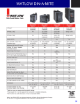
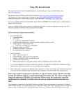
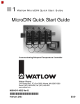
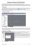
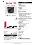
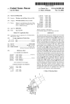
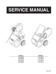
Series 92
User's Manual
TOTAL
CUSTOMER
SATISFACTION
DIN Rail Mount
Limit or Temperature
Control
3 Year Warranty
ISO 9001
Registered Company
Winona, Minnesota USA
Watlow Controls
Watlow Controls, 1241 Bundy Blvd., P.O. Box 5580, Winona, MN 55987-5580, Phone: 507/454-5300, Fax: 507/452-4507
0600-0020-0000 Rev. B
March 1998
Supersedes: W092-MA10-9311
(1291)
$10.00
Made in the U.S.A.
Printed on Recycled Paper
WATLOW Series 92 User's Manual
1
General Description
The Watlow Series 92 is a DIN rail-mounted (DIN EN
50022) analog control. If a DIN rail is not available, the
Series 92 can be mounted using two screws. The
control mode is ON/OFF, limit or PI. The input for the
Series 92 is a single Type J, K or T thermocouple, or
DIN curve RTD sensor input. For the output device,
choose from an electromechanical relay, switched DC
voltage (open collector), solid state relay, or an optional
variable burst-fired output. Variable burst-fired is only
available with the PI version, and can be used with DC
input solid state relays. Set point options include a
remote or integral setpot assembly.
Specifications
Control Mode
• Heat or cool, factory selectable.
ON/OFF
• Switching hysteresis: Typically 3°F/1.7°C
PI: Time proportional with automatic reset
• Proportional band adjust: Typically 5 to 50°F/2.8 to
27.8°C
• Cycle time, fixed: Typically 6 seconds
• Automatic reset, fixed: Typically 0.25 repeats/minute
Limit
• Latching
• High or low, factory selectable
• Internal reset switch and/or customer supplied
remote reset switch. Automatic reset on power loss.
Operator Interface
• LED indication of limit condition or status of load.
• Setpot.
• Dial scale calibrated to compensate for sensor
non-linearities.
• Dual °F & °C scales.
• Remote or integral.
Input
• Thermocouple or RTD available.
• Thermocouple may be isolated or grounded.
• Thermocouple, automatic cold junction compensation.
• RTD input 2 or 3 wire, platinum 100 @ 0°C calibrated for #3850 (DIN): 0.003850 / °C. Contact
Watlow for #3916 (JIS) 0.003916 / °C)curve.
• T/C and RTD sensor break protection de-energizes
output to protect system.
• Sensor and ranges available:
Thermocouple
J1: J t/c
32 to 600°F or
0 to 315°C
J2: J t/c
32 to 1382°F or
0 to 750°C
K1: K t/c
32 to 2282°F or
0 to 1250°C
T1: T t/c -328 to 662°F or -200 to 350°C
RTD
P1: -328 to 1112°F or -200 to 600°C
2
WATLOW Series 92 User's Manual
• Lead resistance effect for type J, K, or T thermocouple input: 200 of lead resistance will cause
less than 1°F error. Refer to the lead wire
manufacturer's specification on ohms per double
foot for type and gauge of wire.
Output
• Electromechanical relay, Form C, 5A @ 120/
240VAC. Minimum offstate impedance is 20K .
Warranted to 100,000 cycles.
• Solid State Relay, Form A, 0.5A @ 24 VAC minimum, 264 VAC maximum, opto-coupled, zerocrossed switching. Minimum off state impedance
is 20K for output "B", and 31M for output "K".
• Open collector, switched DC signal provides a
minimum turn ON voltage of 3VDC into a minimum
500 load; maximum ON voltage not greater than
32VDC into an infinite load.
• Variable time base, open collector, switched DC,
Form A signal provides a minimum turn ON voltage
of 3VDC into a minimum 500 load; maximum ON
voltage not greater than 32VDC into an infinite load.
Available for PI control only.
Accuracy
• Calibration accuracy and sensor conformity:
± 1% of span maximum, at 77°F ± 5°F (25°C ± 3°C)
ambient and rated line voltage.
• Setpoint Accuracy: < ± 3% of range.
• Temperature stability: Typically ± 5µV / °F ambient
for thermocouple. Typically < 1°F from 32 to 130°F
for RTD.
• Voltage stability: ± 0.01% of span / % of rated line
voltage.
Agency Approvals
• UL, CSA and FM pending.
• Patent pending.
Terminals
• Captive screw, cage clamp connection. 0.155"
(4mm) maximum diameter screwdriver blade.
22 - 12 maximum wire gauge
Power
• Factory selectable.
• 120VAC: 85 to 132VAC, 50/60 Hz.
• 208/240VAC: 175 to 264VAC, 50/60 Hz.
• 6VA power consumption.
Operating Environment
• 30 to 140°F/0 to 60°C.
• 0 to 90% RH, non-condensing.
• Storage Environment: -40 to 158°F/-40 to 70°C.
Weight
• Control:
0.75 lb
(0.34kg)
• Setpot:
0.20 lb
(0.09kg)
Ordering Information
Limit
9 2
3
D
0 0 0
Line Voltage
A = 120VAC
B = 208/240VAC
Control Type
3 = Limit
Control Mode
1 = High (heat)
2 = Low (cool)
Output
D = Electromechanical relay, Form C, 5A
(Warranted to 100,000 cycles)
Input and Range See Page 2 for ranges
J1
J2
K1
T1
P1
=
=
=
=
=
Setpot
0
=
1
=
J t/c
J t/c
K t/c
T t/c
RTD
Separate Remote
Set Point Assembly
A006-0 _ _ _
515
516
517
518
519
Integral
Remote* (order setpot separately, see above)
PI
On/Off
9 2
1
Line Voltage
A = 120VAC
B = 208/240VAC
Control Type
1 = ON/OFF control
Control Mode
1 = Heat
2 = Cool
Output
B = Solid state relay, Form A, 0.5A
C = Switched DC, open collector, non-isolated
D = Electromechanical relay, Form C, 5A
(Warranted to 100,000 cycles)
K = Solid state relay, Form A, 0.5A,
without contact suppression
Input and Range See Page 2 for ranges
J1
J2
K1
T1
P1
=
=
=
=
=
Setpot
0
=
1
=
J t/c
J t/c
K t/c
T t/c
RTD
Separate Remote
Set Point Assembly
A006-0 _ _ _
515
516
517
518
519
Integral
Remote* (order setpot separately, see above)
0 0 0
9 2
2
0 0 0
Line Voltage
A = 120VAC
B = 208/240VAC
Control Type
2 = PI control
Control Mode
1 = Heat
2 = Cool
Output
B = Solid state relay, Form A, 0.5A
C = Switched DC, open collector,
non-isolated
D = Electromechanical relay, Form C, 5A
(Warranted to 100,000 cycles)
K = Solid state relay, Form A, 0.5A
without contact suppression
V = Variable time base, open collector, nonisolated Only available in heat mode.
Input and Range See Page 2 for ranges
J1
J2
K1
T1
P1
=
=
=
=
=
Setpot
0
=
1
=
J t/c
J t/c
K t/c
T t/c
RTD
Separate Remote
Set Point Assembly
A006-0 _ _ _
515
516
517
518
519
Integral
Remote* (order setpot separately, see above)
WATLOW Series 92 User's Manual
3
3.89"
(99 mm)
Installation
3.72"
(95 mm)
2.28"
(58 mm)
0.33"
(8 mm)
0.18"
(5 mm)
1.62"
(41 mm)
1
2 3
4
700
7 8
5 6
9
4.45"
(113 mm)
800
300
500
500
1000
200
1100
600
300
100
700
1300
100
0
750
C
F
TYPE J T/C
LOAD
35mm X 7.5mm
Rail is not included
in the assembly
4.10"
(104 mm)
SERIES 92
3.75"
(95 mm)
BAND
10 11 12 13 14 15 16 17
Release Lever
Figure 1 - Series 92 Dimensions
Mounting
DIN-Rail Mounting the Series 92
1. Place the Series 92 upper mounting clip on the top edge
of the DIN rail. See Figure 2.
2. Press down firmly on the top front edge of the Series 92,
see Figure 2 Mounting for location. The control "snaps"
securely onto the rail. If the control does not snap on,
check to see if the DIN rail is bent. The DIN rail specification is DIN EN 50022, 35 mm X 7.5 mm. Minimum
clipping distance is 1.37" (34.8mm), the maximum is
1.39" (35.3mm).
Removing
Panel
DIN Rail
Upper
Mounting
Clip
Removing the Series 92 from the DIN-Rail
1. Place your fingers on the release lever located at the
base of the Series 92. See Figure 2 Removing.
2. While gently pressing on the top of the case, above
Terminals 1 - 9 (see Figure 2 inset), pull forward on the
release lever.
Lower
Mounting
Clip
Release
Lever
Snap Action
Mounting the Series 92
1. Using the control as a location template, mark both
mounting holes.
2. Drill two 0.19" (5 mm) diameter holes in desired panel
location See Figure 1.
Tap drill size
for Screw/thread size
#29 - 0.136 dia.
#8-32
3.3 mm
M4 x 0.7
Figure 2 - Series 92 Side View Mounting
0.11" Dia.
(3 mm)
4 mounting holes
2.25"
(57 mm)
0.75"
(19.05mm)
2.69" sq.
(68 mm)
1.4"
3.00" sq.
(76 mm)
Figure 3 - Setpot Dimensions
4
WATLOW Series 92 User's Manual
(36 mm)
Installing the Remote Setpot Assembly
1. Drill a 2.25" (57 mm) diameter hole (or use a 2.25", or
2.375" punch) at desired remote setpot assembly location. See Figure 3.
2. Using the dial scale as a location template, center and
mark all four mounting holes on the dial scale with a
center punch.
3. For a bolted dial scale assembly, drill four 0.125" (3 mm)
diameter clearance holes. If you are using a screw
assembly, use a tap drill.
Tap drill size
for
Screw/thread size
#43 - 0.089 dia.
#4-40
#42 - 0.093 dia.
#4-48
Line Voltage
WARNING:
To avoid potential electric shock, use National Electric
Code safety practices when wiring and connecting this
unit to a power source and to electrical sensors or
peripheral devices.
All wiring and fusing must conform to the National
Electric Code and to any locally applicable codes also.
Fuse
L1
L2
1
2
3
4
5
6
7
8
92AX - XXXX - X0XX
120VAC
9
and
92BX - XXXX - X0XX
208/240VAC
Figure 4 - 120 and 240VAC Power Wiring
(determined by your model number)
92X3 - XXXX - X0XX
(Reset Switch
customer supplied)
92XX - XXXX - 10XX
(Remote Setpot)
10 11 12 13 14 15 16 17
N.O.
Momentary
Reset Switch
Green
P3
Black
P2
Red
P1
Remote
Setpot
Assembly
Figure 5 - Reset Switch and Remote Setpot Wiring
(determined by your model number)
WATLOW Series 92 User's Manual
5
Input Wiring
NOTE:
When an external device with a nonisolated circuit common is connected
to the DC (open collector) output, you
must use an isolated or ungrounded
thermocouple.
92XX - XXJ1 - X0XX
92XX - XXJ2 - X0XX
92XX - XXK1 - X0XX
10 11 12 13 14 15 16 17
+
-
92XX - XXT1 - X0XX
Red
k
Figure 6 - Thermocouple Wiring
92XX - XXP1 - X0XX
2 Wire RTD
92XX - XXP1 - X0XX
3 Wire RTD
k
NOTE:
Jumper Terminals 11 and 12
for a 2 wire RTD.
10 11 12 13 14 15 16 17
10 11 12 13 14 15 16 17
S3
S2
S1
S2
S1
Figure 7 - RTD Wiring
NOTE:
Long lead lengths create electrical resistance. There will be approximately +2°C input error for every 1Ωof lead
length resistance, when using a two wire RTD. That resistance, when added to the resistance of the RTD element,
can result in erroneous input to the instrument. To overcome this problem, use a three wire RTD sensor, which
compensates for lead length resistance. When extension wire is used for a three wire RTD, all three extension wires
must have the same electrical resistance. (i.e. same gauge, copper stranded.)
6
WATLOW Series 92 User's Manual
Output Wiring
92XX - XBXX - X000
92XX - XCXX - X000
92XX - XVXX - X000
L2
External
Load
-
L1
N.O.
1
2
3
Fuse
COM
4
5
External
Load
+
6
7
8
1
9
2
3
4
5
6
7
8
9
NOTE:
Contact suppression
is not recommended
for high impedance
loads such as AC
input SSR's.
Figure 8 - Solid State Relay with
Contact Suppression,
Form A, 0.5A
Figure 9 - Switched DC, Open Collector OR
Variable Time Base, Zero Cross
Non-Isolated
92XX - XKXX - X000
92XX - XDXX - X000
L2
L2
External
Load
N.O.
COM
External
Load
L1
L1
Fuse
N.O.
Fuse
COM
N.C.
1
2
3
4
5
6
7
8
9
Figure 10 - Electromechanical Relay with
Contact Suppression
Form C, 5A
1
2
3
4
5
6
7
8
9
Figure 11 - Solid State Relay without
Contact Suppression,
Form A, 0.5A
WATLOW Series 92 User's Manual
7
System Wiring Example
L1
120 VAC
L2
High temp. light
Earth Ground
Coil
High Limit
Mechanical
Contactor
Fuse
11
12
SSR-240-10G-DC1
DC Input
SSR
3 (+)
92A3-1DJ1-0000
Limit Control
Out
1
4
In
2
3
9 +
Heater
5 (-)
10
13
10
+
Red 965A-3CA0-0000
Rear View
Process Sensor
14
11
-
Optional
Normally Open
Momentary Switch
Limit Sensor
çWARNING: The
Series 92 Temperature
Limit Switch should be
mounted in an inconspicuous location to
discourage unauthorized changes to the
set point. Only approved and appropriate
personnel should have
the authority to change
the set point on the
limit switch. Failure to
comply with these
recommendations
could result in damage
to equipment and
property, and injury to
personnel.
120VAC
L1
1
L2
11
1
12
3
2
4 (+)
2
5
3
(-)
Series 965
965A-3CA0-0000
Temperature control
3
5
9
4
10
6
7
3-32VDC
In
(+)
(-)
SSR-240-10G-DC1
DC Input Solid State Relay
1 CR-1
5
6
7
1
8
1
11
Out
24-240VAC
9
1
8
12
13
13
(+)
14
10
10
(-)
15
11
11
12
2
Series 92
92A3-1DJ1-0000
Limit Control
3
16
4
1
13
17
5
18
R
Hi Temp. Light
Figure 12 - Series 92 System Wiring Examples
8
WATLOW Series 92 User's Manual
2
2
14
9
Heater
10
1CR
2
2
Tuning
(cont.)
Tuning Procedure for PI Controls
92X2 - XXXX - X0XX
Initial Settings:
• Proportional band: 5 to 50°F/2.8 to 27.8°C
Maximum proportional band is clockwise (CW),
minimum (CCW). Located on the front of the
control labeled "Band."
•
Cycle time, fixed. Typically 6 seconds.
•
Automatic reset, fixed. Typically 0.25 repeats/
minute
Proportional Band Adjustment:
Rotate the proportional band pot CCW 1/4 turn and
observe system stability. Repeat until the process
temperature begins to hunt (becomes unstable). When
hunting is observed, rotate the pot CW, in small
increments, until the system becomes stable. Some
systems may be stable enough to allow minimum
proportional band (maximum CCW).
Proportional
Band
Reduced Overshoot
Energize the system and allow the process temperature to stabilize. When the system is stable, the load
will cycle at a constant rate.
Set point
Droop
Temperature
After an adjustment is made, the system may become
unstable. Allow sufficient time for the system to
stabilize before making another adjustment.
Time
Figure 13 - PI Adjustment Graph
Variable Time Base
92X2 - XVXX - X0XX
When the time base varies upon load demand, this is
considered variable time base. The ON and OFF time
is proportional to the command signal, but the time
base changes according to the demand. At 50% it's
three AC cycles ON and three AC cycles OFF.
Zero cross SSR's must be used. If you are using
random fired SSR's, the Series 92 will not provide zero
cross output.
NOTE:
The variable time base option is only
available with the PI control type.
Figure 14 - Variable Time Base Example
WATLOW Series 92 User's Manual
9
Glossary
1. Automatic Reset (Integral) - Used in proportional
control systems to automatically pick up any system
droop. This action may be adjustable or fixed, and
adjusts the output level to obtain agreement between actual process temperature and controller set
point.
2. Automatic Reset on Power Loss - The limit
control does not recognize the power outage as a
limit condition. When power is restored, the output
will energize automatically as long as a temperature
limit condition does not exist.
3. Anti Reset - Inhibits reset action when the actual
process temperature is outside the proportional
band.
4. Cycle Time - Time interval between consecutive
turn ons.
8. Switching Sensitivity or Differential - The output
will de-energize when the actual temperature
reaches the set point temperature. The switching
sensitivity or differential is the drop in temperature
required to re-energize the output.
9. Temperature Droop - Phenomenon that occurs in
a proportional control system without reset. As the
proportional band is increased, the average process
temperature may drop to a point that is not the set
point temperature. This action takes place even
though the load has stabilized.
10. Temperature Oscillation or Hunting - Occurs
when the proportional band is too narrow or the
system is upset by some outside source. The
actual process temperature is not controlled within
the proportional band on its extreme temperature
excursions.
5. Manual Reset or Offset - Adjustment used in
control systems to offset any temperature droop
and obtain agreement between actual process
temperature and controller set point.
6. ON/OFF - The output is turned full ON below set
point and stays turned on until the process temperature reaches set point, then the controller turns
the output full OFF. At this point, depending on the
design of the thermal system, the process temperature overshoots the set point temperature by some
degree. As the load cools down below set point (an
amount equal to the switching sensitivity or differential) the output is once again turned full ON.
7. Proportional Band - In a straight time proportional
control system when the actual process temperature is below set point and outside the proportional
band limit, 100% power is applied to the load.
Load temperature may never stabilize. Control is
either full ON or full OFF, not within the proportional
band.
11. Variable Time Base - When the time base varies
upon load demand. The Series 92 at 50% power
level passes three AC cycles on and three AC
cycles off.
12. Zero Switching - Load is activated only during the
time period that the sine wave is going through
zero. This eliminates RFI and EMI radiation
(applies to solid state outputs only).
13.
10
WATLOW Series 92 User's Manual
- Musical Notes are used to alert you to
14.
- The Warning symbol ((lightning bolt)
alerts you to a "WARNING", a safety hazard which
could affect you and the equipment.
15.
- The Caution symbol (exclamation
point) alerts you to a "CAUTION", a safety or
functional hazard which could affect your equipment
or its performance.
When the actual process temperature is above set
point and outside the proportional band limit, 0%
power is applied to the load.
When the actual process temperature is within the
proportional band, the controller will proportion the
amount of power applied to the load, 0 to 100%.
or
important details.
Troubleshooting Chart
Problem
Probable Cause
Poor temperature
control.
The proportional band is not
adjusted properly.
Adjust the proportional band per Tuning.
See Page 9.
The load will
not turn ON.
1. An open sensor.
Repair or replace.
2. The load circuit is open.
Check the fuses, circuit breakers, load,
and wiring. See Line Voltage, Page 5..
3. The AC input is not connected or
is connected improperly.
Check the AC input connections. If not
present or proper, connect per Line Voltage.
See Page 5.
4. A faulty unit.
Contact the factory.
1. The polarity is reversed on the T/C.
Connect per Input Wiring. See Page 6,
Figure 6.
2. A faulty unit.
Remove power to the control and the control
from the system. Apply power to the system
with the control removed. If the load turns
OFF, return the control to the factory. If the
load remains ON, there are other problems in
the system that must be resolved. Consult
the factory.
The unit is out of calibration
Contact Watlow for an RMA number, and
return unit to the factory to be calibrated.
The load will
not turn OFF.
The unit is not controlling to set point.
Returns
1. Call Watlow Customer Service, 507/454-5300, for
a Return Material Authorization (RMA) number
before returning any item for repair. We need this
information:
• Ship-to address
• Bill-to address
• Contact name
• Phone number
• Ship via
• P.O. number
• Symptions and/or special instructions
• Name and phone number of person returning
the material.
2. Prior approval and an RMA number is needed
when returning any unused product for credit.
Make sure the RMA number is on the outside of
the carton, and on all paperwork returned. Ship
on a Freight Prepaid basis.
3. After we receive your return, we will examine it
and determine the cause for your action.
4. In cases of manufacturing defect, we will enter a
repair order, replacement order, or issue credit for
Action
material. A 20 percent restocking charge is
applied for all returned stock controls and
accessories.
5. If the unit is unrepairable, it will be returned to you
with a letter of explanation. Repair costs will not
exceed 50 percent of the original cost.
Warranty
The Watlow Series 92 is warranted to be free of
defects in material and workmanship for 36 months
after delivery to the first purchaser for use, providing
that the units have not been misapplied.
Since Watlow has no control over their use, and
sometimes misuse, we cannot guarantee against
failure. Watlow's obligations hereunder, at Watlow's
option, are limited to replacement, repair, or refund of
purchase price, any parts which upon examination
prove to be defective within the warranty period
specified. This warranty does not apply to damage
resulting from transportation, alteration, misuse or
abuse. This excludes mechanical relays which are
warranted to 100,000 cycles.
WATLOW Series 92 User's Manual
11
Watlow Series 92 User's Manual
Watlow Controls, 1241 Bundy Blvd., P.O. Box 5580, Winona, MN 55987-5580, 507/454-5300, Fax: 507/452-4507
12
WATLOW Series 92 User's Manual
Series 92
Addendum
ç
WARNING: The Series 92 Temperature Limit Switch should be
mounted in an inconspicuous location to discourage unauthorized changes to
the set point. Only approved and appropriate personnel should have the
authority to change the set point on the limit switch. Failure to comply with
these recommendations could result in damage to equipment and property, and
injury to personnel.
Watlow
Controls
1241 Bundy Blvd., P.O. Box 5580
(1264)
Addendum to 0600-0020-0000 Rev A
January, 1998
Winona, MN 55987-5580
Phone: 507-454-5300, Fax: 507-452-4507
WATLOW Series 92 User’s Manual
8a