1
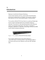
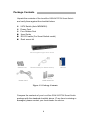
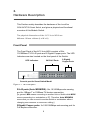
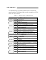
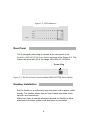
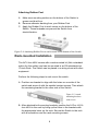
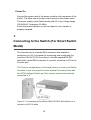
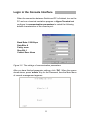
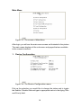
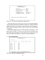
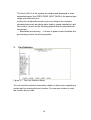
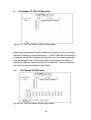
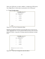
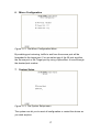
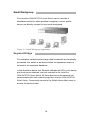
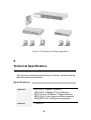
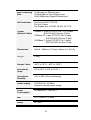
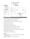
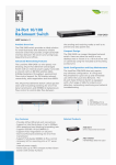
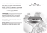
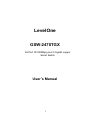
LevelOne
GSW-2470TGX
24-Port 10/100Mbps plus 2 Gigabit copper
Smart Switch
User’s Manual
1
1.
Introduction
Welcome to the World of Network Switching.
In the modern business society, communication and information
sharing are fundamental to our lifestyle. And computer networks
have proven to be one of the fastest means of communication.
The LevelOne GSW-2470TGX Smart Switch is a multi-port Switch that
can be used to build high-performance switched workgroup
networks. This switch is a store-and-forward device that offers low
latency for high-speed networking. The Switch is targeted at
workgroup, department or backbone computing environment at SME
(small, medium enterprise) business.
Figure 1-1. The LevelOne GSW-2470TGX Smart Switch
The LevelOne GSW-2470TGX Smart Switch features a
“store-and-forward “switching scheme. This allows the switch to
auto-learn and store source address on 8K-entry MAC address
table.
2
Features
Conforms to IEEE 802.3, 802.3u, 802.3x and 802.3ab
standard
24 auto-sensing 10/100 Base-TX RJ-45 Ethernet ports,
2 RJ-45 sockets for Gigabit Ethernet
Automatic MDI/MDIX crossover for 10 Base-T, 100
Base-TX and 1000Base-T Ports
Half-duplex mode for backpressure, and full-duplex for
flow control
N-Way Auto-Negotiation supported
Store-and-forwarding switching architecture for
abnormal packet filtering
Performs non-blocking full wire speed (Backplane
Bandwidth 8.8 Gbps)
8K-entry MAC address table
LED indicators for Fast Ethernet: Power, and LK/ACT,
FDX/COL
Gigabit Copper: LK1000, LK100, ACT, FD
19” standard size
3
Package Contents
Unpack the contents of the LevelOne GSW-2470TGX Smart Switch
and verify them against the checklist below.
24TX Switch (Auto MDI/MDIX)
Power Cord
Four Rubber Feet
User Guide
RS-232 cable (For Smart Switch model)
Rack mount kit
24TX+2 Gigabit Copper Smart Switch
Rubber Feet
Power Cord
RS-232 cable (For Smart Switch)
Manual
Rack-mount kit
Figure 1-2. Package Contents
Compare the contents of your LevelOne GSW-2470TGX Smart Switch
package with the standard checklist above. IF any item is missing or
damaged, please contact your local dealer for service.
4
Ethernet Switching Technology
Ethernet Switching Technology dramatically boosted the total
bandwidth of a network, eliminated congestion problems inherent
with Carrier Sense multiple access with Collision Detection
(CSMA/CD) protocol, and greatly reduced unnecessary
transmissions.
This revolutionized networking. First, by allowing two-way,
simultaneous transmissions over the same port (Full-duplex), which
essentially doubled the bandwidth. Second, by reducing the collision
domain to a single switch-port, which eliminated the need for carrier
sensing. Third, by using the store-and-forward technology’s
approach of inspecting each packet to intercept corrupt or redundant
data, switching eliminated unnecessary transmission that slow the
network. By employing address-learning, which replaced the
inefficient receiving port.
Auto-negotiation regulates the speed and duplex of each port, based
on the capability of both devices. Flow-control allows transmission
from a 100Mbps node to a 10Mbps node without loss of data.
Auto-negotiation and flow-control may require disablement for some
networking operations involves legacy equipment. Disabling the
auto-negotiation is accomplished by fixing the speed or duplex of a
port.
Ethernet Switching Technology supplied higher performance at
costs lower than other solutions. Wider bandwidth, no congestion,
and the reduction in traffic is why switching is replacing expensive
routers and inefficient hubs as the ultimate networking solution.
Switching brought a whole new way of thinking to networking.
5
2.
Hardware Description
This Section mainly describes the hardware of the LevelOne
GSW-2470TGX Smart Switch, and gives a physical and functional
overview of this Module Switch.
The physical dimensions of the 24 TX Auto MDIX are:
440mmx 161mm x 44mm (L x W x H)
Front Panel
The Front Panel of the24 TX Auto MDIX consists of 24x
10/100Base-TX RJ-45 ports and 2 Gigabit Copper ports. The LED
Indicators are also located on the front panel of the Switch.
LED Indicators
24 RJ-45 Ports
2 Gigabit
Copper Ports
Console port for Smart Switch Model
Figure 2-1. The Front panel
RJ-45 ports (Auto MDI/MDIX): 24x 10/100Mbps auto-sensing
port for 10Base-T or 100Base-TX devices connection.
[In general, MDI means connecting to another Hub or Switch while MDIX
means connecting to a workstation or PC. Therefore, Auto MDI/MDIX
means that you can connect to another Switch or workstation without
changing non-crossover or crossover cabling.]
2Gigabit Copper ports: 2x 100/1000Mbps auto-sensing port for
Full-duplex connection.
6
LED Indicators
The LED Indicators gives a real-time information of systematic
operation status. The following table provides descriptions of LEDs
status and their meaning.
Table 2-1. The Descriptions of LED Indicators
Ethernet Port
LED
Power
Status
Green
Off
Green
LK/ACT
Blinks
Off
Description
Power On
Power is not connected
The port is connecting with the device.
The port is receiving or transmitting data.
No device attached.
Orange The port is operating in Full-duplex mode.
FD/COL
Blinks
Off
Collision of Packets occurs in the port.
No device attached or in half-duplex mode.
Gigabit Port
LED
LK1000
Status
Green
Off
LK100
Green
Off
ACT
Green
/Blinks
Off
FD
Description
The port is operating at the speed of
1000Mbps.
No device attached.
The port is operating at the speed of 100Mbps.
No device attached.
The port is receiving or transmitting data.
No device attached.
Orange The port is operating in Full-duplex mode.
Off
No device attached.
7
Figure 2-2. LED Indicators
Rear Panel
The 3-pronged power plug is located at the rear panel of the
LevelOne GSW-2470TGX Smart Switch as show in the Figure 2-3. The
Switch will work with AC in the range 100-240V AC, 50-60Hz.
Power Plug
Figure 2-3. The Rear Panel of the LevelOne GSW-2470TGX Smart Switch
Desktop Installation
Set the Switch on a sufficiently large flat space with a power outlet
nearby. The surface where you put your Switch should be clean,
smooth, level and sturdy.
Make sure there is enough clearance around the Switch to allow
attachment of cables, power cord and allow air circulation.
8
Attaching Rubber Feet
A. Make sure mounting surface on the bottom of the Switch is
grease and dust free.
B. Remove adhesive backing from your Rubber Feet.
C. Apply the Rubber Feet to each corner on the bottom of the
Switch. These footpads can prevent the Switch from
shock/vibration.
Figure 2-4. Attaching Rubber Feet to each corner on the bottom of the Switch
Rack-mounted Installation
The 24TX Auto MDIX comes with a rack-mounted kit (Not a standard
option for this switch) and can be mounted in an EIA standard size,
19-inch Rack. The Switch can be placed in a wiring closet with other
equipment.
Perform the following steps to rack mount the switch:
A. Position one bracket to align with the holes on one side of the
switch and secure it with the smaller bracket screws. Then attach
the remaining bracket to the other side of the Switch.
Figure 2-5. Attach
mounting brackets
with screws
B. After attached both mounting brackets, position the 24 Port 10/100
Auto MDIX in the rack by lining up the holes in the brackets with
the appropriate holes on the rack. Secure the Switch to the rack
with a screwdriver and the rack-mounting screws.
9
Power On
Connect the power cord to the power socket on the rear panel of the
Switch. The other side of power cord connects to the power outlet.
The power supply in the Switch works with AC in the voltage range
100-240VAC, frequency 50~60Hz.
Check the power indicator on the front panel to see if power is
properly supplied.
3.
Connecting to the Switch (For Smart Switch
Model)
The Console port is a female DB-9 connector that enables a
connection to a PC or terminal for monitoring and configuring the
LevelOne GSW-2470TGX Smart Switch. Use the supplied RS-232
cable with a male DB-9 connector to connect a terminal or PC to the
Console port.
The Console configuration (out of band) allow you to set your Switch
to enable a user at a remote console terminal to communicate with
the 24TX Intelligent Switch as if the console terminal were directly
connected to it.
Figure 3-1. Connecting the LevelOne GSW-2470TGX Smart Switch to a
terminal via RS-232 cable
10
Login in the Console Interface
When the connection between Switch and PC is finished, turn on the
PC and run a terminal emulation program or Hyper Terminal and
configure its communication parameters to match the following
default characteristics of the console port:
Baud Rate: 19200 bps
Data Bits: 8
Parity: none
Stop Bit: 1
Control flow: None
Figure 3-2. The settings of communication parameters
After you have finished parameter settings, click “OK“. When the screen
shows above, press “admin“ Key for the Password, then the Main Menu
of console management appears.
11
Main Menu
Figure 3-3. The screen of Main Menu
After login, you will see the main menu screen as illustrated in the picture.
The main menu displays all the sub-menu and pages that are available
in the console interface.
1.
Device Configuration
Figure 3-4. The Device Configuration menu
Pick up the selection you would like to change the status and to toggle
the Enable / Disable field and type in appropriate value in the Aging Time
and Priority field.
12
Figure 3-5. The Device Configuration Setup menu
• Broadcast Storm Prevention can be set to 6% or 20% beside Disable.
The percentage indicates the allowance against the capacity. When its
disable there will be no limitation on the incoming rate of broadcast /
traffic, otherwise limitation on those traffics will be set to the percentage
accordingly.
•There are two different mode of VLAN supported in this system – Port
Base VLAN, MTU/MDU. The choice you made here will ultimately decide
the VLAN mode and function for entire system (the configuration of the
other two VLAN mode will have no effect to the system behavior).
2. Port Configuration
Figure 3-6. The Port Configuration Menu
13
The Ports (24+2) of the system are divided and displayed in three
separated pages. Use PREV PAGE, NEXT PAGE to list desired port
range and select the port.
In the port configuration screen you can configure the common
characteristics such as admin state, duplex, speed negotiation, and
flow control, as well as the following special features provided with
the system:
• Bandwidth provisioning - 8 levels of speed control facilitate the
provisioning control for access provider.
3.
Port Statistics
Figure 3-7. The Port Statistics Menu
You can view the statistics information display in this screen regarding a
certain port by entering the port number. You can also refresh or reset
the counter as you wish.
14
4.
Port Based VLAN Configuration
Figure 3-8. The Port Based VLAN Configuration
Assigning physical ports within workgroup is simple, and is a common
method of defining a virtual workgroup – VLAN. It delivers the benefit of
broadcast control and simplifies configuration for the network manager.
One advantage of the Port-Based VLAN is its simplicity and easy to
configure, however, limited security is its drawback – anyone can plug
into the port and gain access to the VLAN.
4.1.
Port Based VLAN Setup
Figure 3-9. The Port Based VLAN Setup Menu
15
Select the VLAN entry to create, modifies, or deletes the VLAN group.
Use <Space Bar> to check (join) or quit port(s) to the VLAN group.
5.
Trunk Configuration
Figure 3-10. The Trunk Configuration Menu
Multiple links between switches can be grouped (trunk) to work as one
virtual, aggregate link. You can create 4 trunks at a time; each trunk can
hold up to 8 ports - only ports of the same speed can belong to a single
trunk.
Figure 3-11. The Trunk Configuration selection Menu
16
6.
Mirror Configuration
Figure 3-12. The Mirror Configuration Menu
By enabling port mirroring, traffic to and from the source port will be
forwarded to the target port. You can select any of the 26 port as either
the Source port or the Target port by using <Space Bar> to scroll though
the desired port number.
7.
System Setup
Figure 3-13. The System Setup menu
The system can let you to reset all configuration or restart the device as
you wish anytime.
17
8.
User Password
Figure 3-14. The User Password menu
The menu provides user to change their password for security use.
4.
Network Application
This section provides you a few samples of network topology in
witch the Switch is used. In general, the LevelOne GSW-2470TGX
Smart Switch is designed to be used as a segment switch. That is,
with its large address table (8K MAC address) and high performance,
it is ideal for interconnecting networking segments.
You can use the LevelOne GSW-2470TGX Smart Switch to connect
PCs, workstations, and servers to each other by connecting these
devices directly to the Switch. The switch automatically learns nodes
address, which are subsequently used to filter and forward all traffic
based on the destination address.
By using Uplink port, the Switch can connect with another switch or
hub to interconnect each of your small switched workgroups to form
a larger switched network.
18
Small Workgroup
The LevelOne GSW-2470TGX Smart Switch can be used as a
standalone switch to which personal computers, server, printer
server, are directly connect to form small workgroup.
Figure 4-1. Small Workgroup Application
Segment Bridge
For enterprise networks where large data broadcasts are constantly
processed, this switch is an ideal solution for department users to
connect to the corporate backbone.
In the illustration below, two Ethernet switches with PCs, print server,
and local server attached, are both connect to the LevelOne
GSW-2470TGX Smart Switch. All those devices in this network can
communicate with each other through the LevelOne GSW-2470TGX
Smart Switch. Connecting servers to the Switch allow other users to
access the server’s data.
19
Figure 4-2 Department Bridge Application
5.
Technical Specification
This section provides the specifications of Switch, and the following
table lists these specifications.
Specifications
Standard
IEEE 802.3 10Base-T Ethernet,
IEEE 802.3u 100Base-TX Fast Ethernet
IEEE 802.3ab 1000Base-T Gigabit Ethernet
IEEE 802.3x Flow Control and Back-pressure
ANSI/IEEE 802.3 N-Way Auto-negotiation
Protocol
CSMA/CD
20
Max Forwarding
Rate
14,880 pps per Ethernet port,
148,800 pps per Fast Ethernet port
1488,000pps per Gigabit Ethernet port
LED Indicators
Per Port: LK/ACT, FD/COL
Per Unit: Power
Per Gigabit port: LK1000, LK100, ACT, FD
Copper
Network Cables
10Base-T: 2-pair UTP/STP Cat. 3, 4, 5 cable
EIA/TIA-568 100-ohm (100m)
100Base-TX: 2-pair UTP/STP Cat. 5 cable
EIA/TIA-568 100-ohm (100m)
1000Base-T: 4-pair UTP/STP Cat. 5 cable
EIA/TIA-568 100-ohm (100m)
Dimensions
Switch : 440mm x 161mm x 44mm (L x W x H)
Weight
2.2Kg
Storage Temp.
-40ºC to 70ºC ( -40ºF to 158ºF)
Operational
Temp.
0ºC to 45ºC ( 32ºF to 113ºF )
Operational
Humidity
10% to 90% (Non-condensing)
Power Supply
100-240V AC, 50-60Hz
Internal universal power supply
Power
Consumption
36 Watts (AC), 12W (DC)
EMI
FCC Class A, CE Mark
Safety
UL, cUL
21
22