1
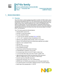
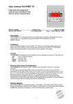
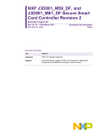
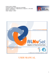
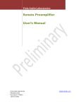
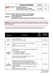
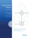
European Laboratory for Particle Physics
Laboratoire Européen pour la Physique des Particules
CH-1211 Genève 23 - Suisse
JCOP Framework
Hierarchical Controls
Configuration & Operation
Document Version:
Document Date:
Document Status:
Document Author:
1
28-Jun-2001 (Updated 10-February-2004)
Draft
Clara Gaspar
Abstract
This document describes the integration of an FSM tool - SMI++ - with the JCOP Framework.
The FwFSM Tools available allow the creation of hierarchies of Finite State Machines.
1 Introduction
The hierarchical controls part of the framework allows the definition and operation of
hierarchies of objects behaving as Finite State Machines. This allows for the sequencing and
automation of operations. In the following chapters we will describe briefly the architecture,
the implementation and finally the tools available.
1.1 Controls Hierarchy Architecture
The mechanism adopted for modelling the structure of sub-detectors, sub-systems and
hardware components in a consistent fashion is to use a hierarchical (tree like) structure. This
tree is composed of two types of nodes: “Device Units” which are capable of monitoring and
controlling the equipment to which they correspond and "Control Units" which are
considered to contain Finite State Machine(s) which can model and control the sub-tree
bellow them. As shown in Figure 1. In this Hierarchy "Commands" flow down and "Status
and Alarm Information" flow up.
Template
page 1
JCOP Framework
Hierarchical Controls
Version/Issue: 1/1
Figure 1: Generic Architecture
1.2 Components and their Interfaces
Each component in the tree (Device or Control Unit) provides Information and can receive
Commands. From the point of view of hierarchical control, the Interface between
Components and Components and Operators is "State" flowing up and "Command" flowing
down - State/Command Interface.
1.3 Operators & Ownership
In order to be able to send commands to the different components an operator can reserve the
whole tree or a sub-tree in which case he/she becomes the "owner". Each component has one
and only one owner at any time. All components of a sub-tree have the same owner.
The components can receive commands from only one or from more operators depending on
their Exclusivity mode:
page 2
•
Exclusive mode - only the owner can send commands.
•
Shared mode - any other operator with the correct access rights can also send
commands.
Template
SDLT
1 Introduction
Single File Template
Version/Issue: 2/1
Only the owner can change from one mode to the other.
1.4 Control Units
Control Units are logical decision units. They can take decisions and act on their children (i.e.
send them "Commands") based on their "States". Any Control Unit and the associated
sub-tree can be a self-contained entity. The logic behaviour of a Control Unit is expressed in
terms of Finite State Machines. State transitions can be triggered by:
•
Command Reception (either from its parent or from an operator)
•
State changes of its children
State transitions cause the evaluation of logical conditions and possibly "Commands" to be
sent to the children.
This mechanism can be used to propagate actions down the tree, to automate operations and
to recover from error situations.
1.5 Device Units
Device Units implement the interface with the lower level components (Hardware or
Software). They are always a tree "leaf" (i.e. they have no children). They do not implement
logic behaviour. They receive:
•
"Commands" and act on the device
•
device data and translate it into a "State".
1.6 Partitioning Modes
Each Control Unit knows how to partition "out " or "in" its children. Excluding a child from
the hierarchy implies that it’s state is not taken into account any more by the parent in its
deciding process, that the parent will not send commands to it and that the owner operator
releases ownership so that another operator can work with it. Only the owner can exclude a
component from the hierarchy.
It was felt that Excluding completely a part of the tree was not enough so the following
Partitioning Modes were defined, as in the graphical representation of Figure 3.:
•
Included - A component is included in the Hierarchy, it receives "Commands" from
and sends its "State" to its parent. It has the same owner as its parent.
•
Excluded - A component is excluded from the hierarchy, it does not receive
"Commands" and its "State" is not taken into account by its parent. It has no owner.
The component is either faulty or ready to work in stand-alone, for calibration, tests,
etc.
Template
page 3
JCOP Framework
Hierarchical Controls
Version/Issue: 1/1
•
StandAlone - A component is working in stand-alone, it does not belong to the
hierarchy anymore (it became the root of a new hierarchy) and has a new owner.
Figure 2: Partitioning Components
page 4
•
CommandsDisabled - A component is partially excluded from the hierarchy, it does
not receive "Commands" but its "State" is still taken into account by its parent. An
expert wants to work on it (to fix quickly a problem) since the experiment will not
continue until it is fixed.
•
Manual - A component is partially excluded from the hierarchy, the expert is working
on it. The expert is the owner, he/she wants to send commands in an exclusive way
•
Ignored - A component can be ignored meaning that its "State" is not taken into
account by the parent but it still receives "Commands". This mode can be useful if a
component is reporting the wrong state (or is only partially faulty) and the operator
wants to proceed.
Template
SDLT
2 Controls Hierarchy Implementation
Single File Template
Version/Issue: 2/1
Figure 3: Partitioning Modes
2 Controls Hierarchy Implementation
The hierarchy is composed of Device Units and Control Units. In order to create and configure
components of these types we need to know what they are:
Device Units: A Device Unit corresponds to a Datapoint of a certain Datapoint Type. Device
Types containing an entry in _FwDeviceDefinition are automatically recognized as
Framework Device Types.
Control Unit: Is a complex entity comprizing PVSS datapoints (containing information about
label, panel, ownership, exclusivity modes, etc.) and Finite State Machine processes
(providing information on objects, states, possible actions, etc.). PVSS communicates with the
FSM processes via an API Manager - PVSS00smi.
The Finite State Machine (FSM) toolkit incorporated in the framework is called SMI++ (State
Management Interface), very briefly, SMI allows the description of any sub-system as a
collection of objects, each object behaving as a FSM, i.e., objects are allways in a well-defined
state and can receive actions that will make them transit to another state. A logically related
group of objects (a sub-system) is called in SMI terms: a domain.
SMI defines two types of objects: abstract objects and physical objects:
Template
page 5
JCOP Framework
Hierarchical Controls
Version/Issue: 1/1
•
Abstract objects implement logic bahaviour, they have a list of allowed states, in each
state a list of allowed actions and when an action gets triggered (either by the
reception of a command or by a state change of another object) they execute
instructions like sending commands to other objects or testing the state of other
objects. The behaviour af the object is coded using a very simple language called
SML.
•
Physical objects implement the interface to real devices, they also have a list of
allowed states, and in each state a list of allowed actions, but when they receive a
command they have to act on the device they model, and when the device’s data
changes they have to maybe change state. Physical objects can be coded in any
language (C, C++, or using PVSS scripts).
A Device Unit corresponds to an SMI physical object.
A Control Unit corresponds to an SMI domain, i.e. it is composed of one or more (abstract
and/or physical) objects.
SMI like PVSS allows the definition of object types and the derivation of objects from the type.
So in order to create a hierarchy it is necessary to:
•
Create any Device Types (i.e. the types from which Device Units will “inherit”)
•
Create any Object Types (i.e. the types from which any abtract objects will “inherit”)
•
Create Control Units (i.e. instanciate the devices and/or abstract objects and include
them in a particular domain).
The following steps are necessary in order to create/configure a Device Type:
•
Create a Datapoint Type (or use an existing one, the one that implements the device)
•
Use the FSM Configuration Tool to:
•
Define wich states this device can have
•
Define the allowed actions in each state
•
Define how the state is derived from the device’s datapoint items
•
Define how the actions act on the device’s datapoint items
The following steps are necessary in order to create/configure an Object Type:
•
Use the FSM Configuration Tool to:
•
Create a new abstract object type
•
Define wich states this object can have
•
Define the allowed actions in each state
•
provide the action “code” with the help of the “wizard”
The following steps are necessary in order to create/configure a Control Unit (i.e. an SMI
domain)
•
After having created the necessary device and object types
•
Use the FSM Configuration Tool to:
•
page 6
Create a new domain (either as tree root or under another one)
Template
SDLT
2 Controls Hierarchy Implementation
•
Single File Template
Version/Issue: 2/1
Add Objects and /or Devices to it by:
•
choosing the Object/Device type
•
providing a name
The system is then ready to be operated, the Control Unit domains can be started (or stopped,
etc.) and generic panels to visualize and control them and their objects and devices are
available.
Template
page 7
JCOP Framework
Hierarchical Controls
Version/Issue: 1/1
3 The FSM Configuration & Operation Tool
3.1 Defining Device Types and Object Types
Device Types: Represent User Devices,
they correspond to Data Point Types
created by the User which contain a folder
called “fwDeclarations” of type reference
“_FwDeclarations”. This folder is the
interface to the above levels of the Control
System).
Logical Object Types: Represent abstract
objects which contain the logical behaviour
of the system. They are dynamically
created.
page 8
Template
SDLT
3 The FSM Configuration & Operation Tool
Single File Template
Version/Issue: 2/1
3.2 Configuring Device Types
List of states the Device can be in, these
can be added or removed directly in this
panel or by clicking on “Simple Config”.
The panel specific to this device type
(will be called at run-time). By default the
panel has the same name as the device
type, but it can be changed here.
List of Actions that the
Device can accept in
each state, these can be
added
or
removed
directly in this panel or
by clicking on “Simple
Config”.
Each state has a color to be seen at run-time
Template
After having defined the states
and actions of the object, click
here to specify how the state is
derived from the Device’s
DataPoint items and how the
actions act in the Device’s
DataPoint items (if not done by
the “Simple Config”).
page 9
JCOP Framework
Hierarchical Controls
Version/Issue: 1/1
3.3 Simple Device Config
The “Simple Config” allows the definition of the States (and state colors) of the Device,
of the actions allowed in each state and for each action the expected end-state.
Specify here what Datapoint item is used to
compute the new state and what datapoint item is
set when an action arrives. This panel will
generate simple scripts, for more complex
behaviour please use the “Configure Device”
button on the previous panel.
page 10
Template
SDLT
3 The FSM Configuration & Operation Tool
Single File Template
Version/Issue: 2/1
3.4 Complex Device Config: from DP Items to Device States
Configuring device states: Select the item(s) and what values it/they should have
in order for the device to be in a particular state. Clicking on “Apply” will generate
a script that you can modify by clicking on the “Complex Parametrization” button.
Note: clicking on “Apply” after having modified the script will overwrite it.
Template
page 11
JCOP Framework
Hierarchical Controls
Version/Issue: 1/1
3.5 An example Script that calculates the new State
page 12
Template
SDLT
3 The FSM Configuration & Operation Tool
Single File Template
Version/Issue: 2/1
3.6 Complex Device Config: from Device Actions to DP Items
Configuring device actions: Select the item(s) and what values it/they should be
set to when an action is received. Clicking on “Apply” will generate a script that
you can modify by clicking on the “Complex Parametrization” button.
Note: clicking on “Apply” after having modified the script will overwrite it.
Template
page 13
JCOP Framework
Hierarchical Controls
Version/Issue: 1/1
3.7 An example Script called when an Action is received
page 14
Template
SDLT
3 The FSM Configuration & Operation Tool
Single File Template
Version/Issue: 2/1
3.8 Configuring Object Types
List of states the Object can be in, these
can be added or removed directly in this
panel or by clicking on “Simple Config”.
The panel specific to this object type
(will be called at run-time). By default
the panel has the same name as the
object type, but it can be changed here.
List of Actions that the
Object can accept in each
state, can also be done in
“Simple Config”. By double
clicking on each action you
can see/modify the FSM
code corresponding to this
action
Each state has a color to be seen at run-time
Template
List of conditions that can trigger an
action or a state change while in this
state. By clicking on “Add” you can
specify a new “when” condition, by
double clicking on one of them you
can modify it. ”Simple Config” can
also generate conditions.
page 15
JCOP Framework
Hierarchical Controls
Version/Issue: 1/1
3.9 Simple Object Configuration
The “Simple Config” allows the definition of the States (and state colors) of the
Device, of the actions allowed in each state and for each action the expected endstate.
This panel will generate the FSM code for
the object, you can view it and modify it for
more complex behaviour by double clicking
on each state in the previous panel.
page 16
Template
SDLT
3 The FSM Configuration & Operation Tool
Single File Template
Version/Issue: 2/1
3.10 Example FSM Action code
Example of FSM code corresponding to an
Action. It can be modified directly or with the
help of a wizard obtained by selecting an
instruction in the menu.For example “do”:
Template
page 17
JCOP Framework
Hierarchical Controls
Version/Issue: 1/1
3.11 Example FSM “when” condition wizard
page 18
Template
SDLT
3 The FSM Configuration & Operation Tool
Single File Template
Version/Issue: 2/1
3.12 Configuring Hierarchies of FSM Domains
This tree represents a hierarchy of FSM
domains. Each domain can be expanded or
collapsed by double clicking on it. You can
Add/Remove domains using the “Add” and
“Remove” buttons or the right mouse button
when the domain is selected.
By double clicking here (on the domain
name) you can configure it. The “CU” flag
stands for “Control Unit” meaning this is a
domain or just a device.
The domains have to be regenerated if the
Object or Device types are modified.
Template
page 19
JCOP Framework
Hierarchical Controls
Version/Issue: 1/1
3.13 Configuring FSM Domains
Label and Panel of this domain, to be used
at run-time.
List of Objects and Devices in this domain,
to be added or removed by using the “Add”
and “Remove” buttons
If an Object or Device is added with “CU”
flag set, this means create also an
independent domain for it
page 20
Template
SDLT
3 The FSM Configuration & Operation Tool
Single File Template
Version/Issue: 2/1
3.14 Operating the Hierarchy of Domains
This tree represents a hierarchy of FSM
domains. Each domain can be started,
stopped or restarted by itself or all
domains at the same time. You can
visualize the domains and send
commands to them by using the right
mouse button (once they are running).
Template
page 21
JCOP Framework
Hierarchical Controls
Version/Issue: 1/1
3.15 Operating the FSM Domains
Domain’s top level Object :
Name, State and Partitioning mode
Click on State for sending actions
Click on partitioning mode for
changing mode
Domain’s Children (other Domains, Objects or
Devices) :
Name, State and Partitioning mode
Double Click on Name to open panel
Click on State for sending actions
Click on partitioning mode for changing mode
User
Specific
Logo
Domain
Specific
panel
page 22
Template