1
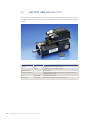
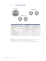
TW
MotorS with integrated
Servodrive
User Manual
Conformities
Declaration of Conformity
For PMC components there are declarations of conformity
available. These declarations confirm that the components
are designed according to valid EC directives. If required,
you can ask your sales representative for these declarations.
Low-Voltage Directive
The PMC products of a drive system mentioned in this
documentation comply with the requirements of the EC
Directive (see page 67).
Safety Instruction
Please read before the initial startup. See page 73.
EMC Directive
The PMC products of a drive system mentioned in this
documentation comply with the requirements of the EC
Directive (see page 67).
CE Label
TW
MotorS with integrated
Servodrive
User Manual
Supported Models
Size 3
302.50.4
Size 7
720C.40.3
730C.30.3
740C.20.3
summ
summary
1
introduction
torquewire Motors
1.1 TW motors with integrates servodrive . 8
1.2 Content of the package .................. 9
1.3 Optional CANPS-S1 – CAN Ixxat
Interface module .......................... 9
1.4 Optional brake unit and power supply . 9
2
electrical installation
2.1
2.2
2.3
2.4
General connections design .......... 30
Power connections ...................... 00
Signal connections: CAN protocol ... 13
Signal connections: EtherCAT
protocol ................................. 14
3
Software
3.1 Motor Led Behaviour ................... 16
3.2 Drive functionality ...................... 17
3.3 Standard CANOpen setting ........... 17
4 | tw motors with integrated Servodrive
mary
4
tw Motor: size 3
7
4.1
4.2
4.3
4.4
4.5
4.5
Technical data ............................ 20
Mechanical drawings ................... 20
Torque (Nm) versus Speed (rpm) ... 21
Motor/drive technical data ........... 21
Standard Connectors ................... 22
New Connectors.......................... 22
7.1 TW-S Single phase ...................... 34
7.2 TW-T Three phase ....................... 34
7.3 CAN-PC Interface Board .............. 34
5
tw Motor: size 7
8.1 ? .............................................. 36
5.1
5.2
5.3
5.4
5.5
Technical data ............................ 24
Mechanical drawings ................... 24
Torque (Nm) versus Speed (rpm) ... 25
Motor/drive technical data ........... 25
Connections ............................... 26
9
6
Ce conformity
6.1
6.2
6.3
6.4
Introduction: EC directives ........... 28
LVD Directive ............................. 28
Product Safety ........................... 28
Application as Directed – Scope of
Application ................................ 29
Installation ................................ 29
EC Declaration of Conformity and
Directive EMCD .......................... 29
The EMCD directive 2004/108/CE
Installation as Specified .............. 30
EC Declaration of Conformity ....... 31
6.5
6.6
6.7
6.8
6.9
8
tw accessories
tw Motors:
permissible shaft load
safety instruction
9.1 Important directions for use ......... 38
9.2 Safety Instructions for Electric Drives
and Controls .............................. 39
9.3 Instructions with Regard to Specific
Dangers ..................................... 41
appendix
Service and Support ........................... 48
Summary | 5
1
introduction:
torquewire
motors
Phase Motion Control
TW Motors with Integrated Servodrive
T
he new TorqueWire series of integral servo systems sets a new style in complex
automatic machinery architecture. TorqueWire motors are complete, self sufficient servo axis building blocks which allow the design, integration and operation
of large multi axis systems with minimum hardware and surprising ease. The
TorqueWire motor system consists of an advanced, high performance rare earth
brushless servo motor, a DSP based, high voltage interpolating servo drive and a single or
multi turn absolute encoder, all assembled in a very compact IP 67 protected frame.
The motor systems are controlled via a multi drop CANOpen field bus (or EtherCAT filed
bus), linking together groups of motors on a single bus system. The motors are supplied from
a common DC bus and braking energy from any drive is intrinsically recycled on any other
axis on the network. The performance of TorqueWire originates in the advanced design of
both motor and drives.
The motor parts take advantage of a novel, patent pending winding design, along with new
magnetic materials and a special winding technique, all of which result in a servo motor with
about 60% of the size of a conventional servo design. Such advantage is invested in both
temperature rise derating and space for the drive, so that TorqueWire motors, including the
drive, are smaller than comparable motors with similar rating.
The built-in, DSP based drive is a step forward in power drive miniaturization. According to
the established Phase drive technology, neither electrolytic capacitors nor any components
subject to ageing of temperature decay are used. All magnetic are planar, integrated in the
drive PCB.
The drive is an ultra compact, single board unit in high density SMD technology with no
massive components and is vibration tested to 200 Hz, 5g. The drive is conformal coated
and sealed; connection is via IP 67 industrial circular connectors. Drive temperature, long
considered the limiting factor in integral drives, is controlled with an accurate strategy; all
components are rated for 120 °C operation, while the drive is temperature limited at 100
°C. The DSP senses motor temperature, power device temperature, and drive ambient temperature.
All these data are available on the bus for application monitoring and optimization. Drive
loss and EMI are minimized intrinsically by the drive location, with zero wiring stray capacitance and minimized winding capacitance. In general, all servo systems are intrinsically
limited in performance by the S/N ratio of the encoder signal. In the TW motors, the interpolating drive is positioned in close proximity of the encoder, thus ensuring the best possible
position signal quality and integrity; the servo performance is consequently optimal.
1.1
TW motors with integrated
servodrive
The CANOpen protocol implementation of the TW series is in full compliance with the standards DS 301 and device profile drives DSP 402v2.0. TW drives are controlled in space,
speed or torque. The servo loops are updated at 4 kHz frequency.
In the interpolated mode, a position profile synchronized with other axes is followed with a
maximum throughput of 500 samples/sec, corresponding to a maximum mechanical bandwidth of 250 Hz, far in excess of the best mechanical systems available; The TW interpolates
points with a second order spline. A separate, programmable, hardwired I/O which overrides
all software instructions is provided to cater for machine safety requirements. The 2 wires,
optically isolated digital interface, and the suppression of all other interfaces, grants reliability, fault tolerance and ease of installation, especially in multi axis systems.
The motors can be programmed and monitored via the CAN Cockpit configuratore windows
interface (supplied with all TW motors). All TW motors embody a non volatile memory to
store permanent data, settings and fault conditions irrespective of power supply availability.
8 | TW Motors with Integrated Servodrive
1.2
Content of the package
Tw Motor with integrated servodrive including:
•
•
•
•
absolute multi-turn (N), absolute single-turn (M) encoder or two-poles resolver (R);
optional integrated holding brake (B);
optional shaft forelock (K);
CANOpen compatible (CiA DS301 V4.02 and DSP402 V2.0) drive, profile position, profile velocity, homing mode, interpolated mode, rotary table and torque profile (Tw specific);
• default values on the parameters table (§4).
Cdrom Phase Motion Control including:
•
•
•
•
•
user manual;
software manual;
a copy of the firmware and the related parameters table;
Cockpit software (§6);
Phase Motion Control products’ documentation.
For a detailed description of all functionalities of the Tw motor, please refer to the Software
manual (§4).
1.3Optional CANPC-S1 – CAN Ixxat
Interface module
The Cockpit configuration tool is useful to create, analyze, modify and copy all parameters
for your applications. This tool has to be installed on a PC, together with the RS232 – CAN
CANPC-S1 converter or with CanUsb-Ixxat converter. The Cockpit let the user to access to
all functionalities and to all parameters of the drive; it can identify the unit, it let to read all
parameters from it and save them on a backup file, it let to load the firmware when necessary. Further, it let to make powerful diagnostic with the Monitor Page, Monitor window and
Graphic window functions (§6).
The Cockpit could be used simultaneously with other devices in the CAN network only if
there is no other systems that try to access via SDO protocol the same Tw that Cockpit is
addressing (§4).
Additionally, with the provided CAN Diagno tool, it is possible to sniffer the traffic on the
CAN bus and to inject customized messages (§5).
1.4Optional brake unit
and power supply
This device make straightforward the commissioning of the Tw motors, as it combine in
one system a power supply (EMI filter + rectifier bridge + capacitor filters, input supply of
220/380Vac, output supply of 310/560Vdc, short-circuit protected), a capacitors pre charge
and a clamp unit. It can supply at the same time more than one Tw (§7). The EMI filter is
effective up to a maximum of two Tw motors.
Introduction: TorqueWire Motors | 9
2
electrical
installation
Phase Motion Control
TW Motors with Integrated Servodrive
2.1
General connections design
For the commissioning the Tw motor need only two connections: a supply connection (power
/ holding brake / auxiliary digital input) and a signal connection (CAN bus, passthrough male
and female M12 connectors).
DC link
Brake Supply Unit
Figure 1
General connections design
(TW3 motors)
CANOpen or EtherCAT
communication
CANOpen
line
Master CANopen
TW7
2.2
TW3
Power connections
The integrated servodrive is designed to work with a 540Vdc supply (that is the resulting
rectified and filtered 380Vac) on TW3 e TW7 motors version.
TW7
TW3
Figure 2
Power connections sample
(TW3 motors) with TW-S
Single Phase Supply
(§ 7.1)
DC-
220
Vac
220
Vac
12 | TW Motors with Integrated Servodrive
DC+
As described by the previous drawing, the same DC bus can supply several motors in parallel.
No clamp resistor is integrated into the motor. If the working cycle of the motor requires a
significant braking energy dissipation, a bigger capacitor or an external clamp device should
be installed on the DC bus.
Both power supply and clamp device jobs are done by the optional Brake Unit and Power
Supply module, as shown in the Figure 2.
A nominal current’s sized shielded cable (high-flessibility kind suggested) is required for the
system reliability.
For EMI reduction an external filter (like Schaffner FN 350 series) between AC connection
and rectifier should be installed. However, if the system employs the Brake Unit and Power
Supply Module, it has a built-in filter suitable up to two motor.
On the power connector there is also the software configurable auxiliary digital input that
could be used either as emergency stop or as input to sample internal values by external
event nor as zero point switch in the homing procedures.
When requested, on the power connector there are also the holding brake commands. For
proper operation the holding brake have to be supplied with a 24Vdc; inside the Tw this voltage is galvanic fully isolated from the power supply and from the other signals.
2.3
Signal connections:
CAN protocol
The CAN bus is a network, resistor terminated at the beginning and at the ending side, that
pass through all devices that is linked to the net. It is necessary a twisted pair cable (highflessibility and shielded kind suggested) with line impedance equal to 120Ω; if the overall
network is longer than 25m, it is required right size wires to avoid excessive power loss, as
stated in the following table (referred to a network with no more than 64 nodes):
Bus length [m]
Resistance per length
unit [mΩ/m]
Wires size [mm2 (AWG)]
Termination resistor
(RT) [Ω]
Baudrate [kbit/s]
0...40
70
0.25...0.34 (23…21)
124
1000 at 40 m
40...300
<60
0.34...0.6 (21...19)
150...300
>500 at 100 m
300...600
<40
0.5...0.6 (20…19)
150...300
>100 at 500 m
600...1000
<26
0.75...0.8 (19…18)
150...300
>50 at 1 km
In the Tw motor, in order to let an easier harnessing, there are two M12 connectors, one
male and one female. All signals on the connectors are opto-isolated. The power supply of
the signal interface is self-generated (thus voiding an external specific power supply) and it
is galvanically isolated from the main drive.
Electrical Installation | 13
Drive AxM II
Figure 3
Signal connections sample:
CAN protocol.
TW3
TW7
TW3
TW7
In the previous drawing is illustrated an interconnection sample between different CAN devices (four Tw motors, one AxM servodrive).
Formoredetailsreferto(§1)andto(§4).
2.4
Signal connectionS:
etherCat ProtoCol
The EtherCAT technology overcomes the system limitations of other Ethernet solutions: the
Ethernet packet is no longer received, then interpreted and copied as process data at every
connection. Instead, the Ethernet frame is processed on the fly: the newly developed FMMU
(fieldbus memory management unit) in each slave node reads the data addressed to it, while
the telegram is forwarded to the next device. Similarly, input data is inserted while the telegram passes through. The telegrams are only delayed by a few nanoseconds. EtherCAT can
provide the same communication mechanisms as the familiar CANOpen mechanisms: object
dictionary, PDO (process data objects) and SDO (service data objects) - even the network
managementiscomparable.Formoredetailsreferto(§8).
14 | tw motors with integrated Servodrive
3
SOFTWARE
Phase Motion Control
TW Motors with Integrated Servodrive
3.1
Motor Led Behaviour
The Tw Motor is equipped with two couples of leds, which indicate the motor status (led on
the upper and lower side of the motor give redundant information, except when different
noted).
Led1
Led2
Motor Status
Blinking
Off
Power supply Ok. Power output disabled
On
Blinking
Power supply Ok. Power output enabled
Blinking alternately
Fault condition
Blinking simultaneously
Waiting for firmware download (due to Firmware download activation or
wrong firmware CRC check)
Off
Two fast blink
Low DC link circuit voltage
On (one side)
Off (both side)
Flash memory corrupted, contact technical service
16 | TW Motors with Integrated Servodrive
3.2
Drive functionality
The Tw Motor complies with the CAN 2.0A standard, with 11 bit identifier; furthermore it
complies with the CiA DS301 V4.02 (Application Layer and Communication Profile), with
the following functionalities:
NMT:
Slave only
Baud rate / node-ID:
1000 / 800 / 500 / 250 / 125 / 100 / 50 kbps; node 1 ÷ 127
Server SDO:
1
Tx PDO:
8
Rx PDO:
8
PDO Mapping:
User programmable (only in pre-operational state)
PDO Modes:
All types supported
Emergency object:
Yes
Sync object:
Yes
Time object:
No
Error control protocols:
Boot-up / Node Guarding / Heartbeat
The Tw Motor complies with some functionalities of the CiA DSP402 V2.0 (Device Profile
Drives and Motion Control), that are:
•
•
•
•
•
Profile position mode.
Profile velocity mode.
Interpolated position mode.
Factor group.
Homing mode.
The baud rate and node-id setting are provided by the CiA DSP305 V1.1 (Layer Setting
Services protocol).
The Tw Motor specific functions are:
•
•
•
•
•
Absolute multi-turn or absolute single-turn encoder.
Torque (current) mode.
Auxiliary digital input for emergency disable.
2nd order digital filters.
Rotary table control.
3.3.Standard CANOpen setting
Setting the node number and baud rate is supported by the protocol CiA DSP305 V1.1
(Layer Setting Services protocol).
The factory default setting for the Tw Motor is the following:
Node number:
Baud rate: 1.
125 kbps (according to CiA DS301 V4.02).
Software | 17
4
TW MOTOrS
SizE 3
Phase Motion Control
TW Motors with Integrated Servodrive
4.1
teChniCal data
High torque density, small size, low inertia, high voltage supply, high speed.
Torque continuous 3 Nm, peak 8 Nm.
Maximum power density 650 W in 2.8 kg including drive 5000 rpm operation.
Small diameter for limited pitch multi axis applications.
310 Vdc and 550 Vdc bus compatible.
Universal 14 mm shaft with half key.
Resolver, single turn and real multi turn absolute encoder without battery (17 bits/turn,
4096 turns, 1 arcmin accuracy).
IP 67 protection.
Applications:
• Workpiecesettingforwoodandmetalforming.
• Packaging,bottling,wrapping,especiallyonrotarymachines(singlewirecommendfor
multi axis).
• Toolchangers.
• Laserplotter.
• Pickandplacerobots.
• Mouldautomation.
• Assemblymachines.
4.2
meChaniCal drawingS.
All measurements are in mm, except when specified.
TW motor
302.50.4
302.50.4.B
Units
L1
197.4
227.4
[mm]
L2
167.4
197.4
[mm]
20 | tw motors with integrated Servodrive
4.3Torque (Nm) versus speed (rpm)
7
TW 302.50.4
6
Torque (Nm)
5
4
3
2
Torque cont. S1 (flanged)
1
Torque cont. S1 (free air)
0
Torque max S6 10% (flanged)
0
1000
2000
3000
4000
5000
Speed (rpm)
4.4
Motor/drive technical data
Reference data (winding independent)
Symbol
302.50.4
Units
Nominal Torque, S1, low speed, free air 1)
Tnc
2.36
Nmrms
Nominal Torque, S1, low speed, flanged 2)
Tnw
2.50
Nmrms
Peak Torque, S6 10% 1)
Tpk
6.00
Nmrms
Maximum speed
Pn
800
rad/s
Symbol
302.50.4
Units
Jm
0.094
mkgm²
Acceleration at peak torque
Apk
67000
rad/s²
Mass
Msta
2.8
Kg
Physical data (winding independent)
Rotor inertia
Insulation
Class H-F
IP Protection
Thermal data (winding independent)
IP67
Symbol
302.50.4
Units
Thermal time constant, free air 1)
Tc
400
sec
Thermal time constant, flanged 2)
Tw
145
sec
W
Motor loss at Tnc
LOc
62
Motor loss at Tnw
Low
72
W
Threshold of built-in PTC
PTCt
110
°C
Units
Symbol
302.50.4
Power supply (typical)
Electrical data (winding dependent)
Vn
540
Vdc
Rated speed, flanged 3)
Wn
500
rad/s
Peak current T=Tpk
Ipk
5.50
Arms
Arms
Nominal current at T=Tn
Rated power, flanged, speed.3)
Torque constant
Brake Data (optional)
In
2.0
Pnw
0.60
kW
Kt
1.09
Nmamp-1
Units
Symbol
302.50.4
Supply voltage
Un
24
V
Power consumption
P20
13
W
Stall braking torque
Tbk
7.00
Nm
Additional Inertia
JBk
0.041
mkgm²
1) Motor in free still air (worst case), ambient 40 °C, copper 130 °C, frame 105 °C.
2) Motor mounted on steel flange, temperature flange <= 60°C.
3) Speed achievable only for flanged motor.
TW Motors: Size 3 | 21
4.5
TW3 STANDARD connector
Power Connector
M23 Size
Signal Connector
M12 Size - CAN Protocol Connection
3
2
4
2
6
1
C
Power connector
2
3
FEMALE
MALE
Pin
Description
DC+ 3
1
Shield
4
Connector
Signal Connector
M12 Size - CAN Protocol Connection
2
+24 V Supply2
3
GND6
3
CAN GND3 / O5 V Supply
5
1 Signal Connector
4
4
Auxiliary Input (+24 V)
4
Can-H
5
Can-L
2
1
5
O CV Supply
B
3
5
6
1
+24 V Supply
D
4
2
3
2
FEMALE
3
5
B
Signal Connector
MALE1
1
4
5
2
4
3
FEMALE
MALE
A
4.6
1
M12 Size - CAN Protocol Connection
4
C
2
4
M12 Codfication A
Description
2Power
DC-
5
4
Signal connectors
CONINVERS
6 pins SF-SEP1N8AWA00 MR23
M23 Size
1
1
5
B
Power Connector
Pin
1
5
3
TW3 new connector version
M12 Size - EtherCAT Protocol Connection
Power Connector
2
2
5
3
1
5
3
1
Signal Connector
M12 Size - CAN Protocol Connection
4
4
FEMALE
FEMALE
2
3
1
4
2
3
D
B
Signal Connector
1
1
4
5
4
3
FEMALE
MALE
A
C
5
2
M12 Size - EtherCAT Protocol Connection
2
3
5
2
1
3
5
1
4
4
FEMALE
FEMALE
Power connector
Signal connectors
CONINVERS 8 pins SF-7EP1N8AWA00 MR23
CANOpen protocol
EtherCAT protocol
M12 Codification A
M12 Codification D
Pin
Description
Pin
Description
Pin
Description
1
DC+
1
Shield
1
Tx+
2
GND
2
+ 24 V Supply
2
Rx+
3
DC -
3
CAN GND / O V Supply
3
Tx-
4
O V Supply
4
Can-H
4
Rx-
A
+24 V Input Torque H
5
Can-L
5
N.C.
B
Auxiliary Input (+24 V)
C
+24 V Supply
D
+24 V Input Torque L
22 | TW Motors with Integrated Servodrive
5
TW MOTOrS
SizE 7
Phase Motion Control
TW Motors with Integrated Servodrive
5.1
teChniCal data
The new integrated servo TW7 is able to deliver 20 kW and 65 Nm continuous, 30 kW overload. The system is water-cooled with a single circuit that affects both the motor as the drive
so integrated that reaches levels of extreme compactness and power density, making it ideal
for high power applications in confined spaces and enabling the elimination of the cabinet,
as well as application self-propelled vehicle or rotary tables, with connections to minimize
and control via fieldbus.
The servodrive is produced with resolver (2 poles) or encoder Heidenhain inductive absolute
mono (ECI1319) or multi (EQI1331).
Option available: brake for vertical axis.
The TW series is particularly innovative with regard to electromagnetic compatibility. There
are no cables between motor and drive also between the sensor and drive through the integration, so that the system has a very low RFI emissions and an equally reduced susceptibility to electromagnetic interference.
The drive is designed and validated for a high-level of vibration and temperature, and works
completely without electrolytic capacitors, which enables a particularly high lifetime.
The system is class IP 67 protected.
5.2
meChaniCal drawingS.
All measurements are in mm, except when specified.
Type
A
B
Units
720C
305.2
76.5
[mm]
730C
355.2
127.5
[mm]
740C
406.2
178.5
[mm]
24 | tw motors with integrated Servodrive
5.3Torque (Nm) versus Speed (rpm)
720C.40.3
730C.30.3
80
740C.20.3
150
150
125
40
100
Torque (Nm)
Torque (Nm)
Torque (Nm)
60
75
50
100
50
20
25
0
0
1000
2000
3000
4000
0
5000
0
500
1000
1500
2000
0
2500
0
500
Torque cont. S1 (flanged)
1000
1500
2000
2500
Speed (rpm)
Speed (rpm)
Speed (rpm)
Torque max S6 10% (flanged)
5.4Motor/drive Technical data
Reference data (winding independent)
Symbol
720C.40.3
730C.30.3
740C.20.3
Units
Nominal Torque, S1, low speed, water
cooled H20
Tnc
36,3
55,4
80,5
Nmrms
Peak torque, S6 10% 1)
Tpk
57,3
73,9
107,5
Nmrms
Maximum speed
Pn
600
600
600
rad/s
Symbol
720C.40.3
730C.30.3
740C.20.3
Units
Physical data (winding independent)
Rotor inertia
Jm
1,29 · 10ˉ³
1,85 · 10ˉ³
2,41 · 10ˉ³
kgm²
Acceleration at peak torque
Apk
5,07 · 104
5,30 · 104
5,42 · 104
rad/s²
Mass
Msta
13
18
23
Kg
Units
Insulation
Class H
IP protection
Thermal data (winding independent)
IP 67
Symbol
720C.40.3
730C.30.3
740C.20.3
Tc
372
329
308
s
LOc
0.86 ·10³
1.29 ·10³
1.71 ·10³
W
Motor loss at Tnw
LOw
1.02 ·10³
1.44 ·10³
1.83 ·10³
W
Threshold of built-in PTC
PTCt
130
130
130
°C
Symbol
720C.40.3
730C.30.3
740C.20.3
Units
Vn
540
540
540
Vdc
Rated speed
Wn
419
314
262
rad/s
Peak current T=Tpk
Ipk
48
48
48
Arms
Thermal time constant, water-cooled H20 1)
Motor loss at Tnc
Electrical data (winding dependent)
Power supply (typical)
Nominal current T=Tn
Rated power
Torque constant
Brake Data (optional)
In
30
36
36
Arms
Pnw
14
17
20
kW
Kt
1,35
1,71
2,50
Nmamp-1
Units
Symbol
720C.40.3
730C.30.3
740C.20.3
Supply voltage
Un
24
24
24
V
Power consumption
P20
22.8
22.8
22.8
W
Stall braking torque
Tbk
58
58
58
Nm
Additional Inertia
Jbk
0.13·10ˉ³
0.13·10ˉ³
0.13·10ˉ³
kgm²
1) Motor water-cooled with 30°C water temperature.
2) Connector cooling water-pipe: opposite inlet and outlet version.
TW Motors: Size 7 | 25
6
1
C
5.5
3
B
5
1
5
4
4
3
FEMALE
MALE
2
5
Connections
Power Connector
Signal Connector
M12 Size - CAN Protocol Connection
2
3
1
2
4
3
D
B
Signal Connector
1
1
4
5
4
3
FEMALE
MALE
A
C
5
2
M12 Size - EtherCAT Protocol Connection
2
3
5
2
1
3
5
1
4
4
FEMALE
FEMALE
Power connector
Signal connectors
CONINVERS 8 pins SF-7EP1N8AWA00 MR23
CANOpen protocol
EtherCAT protocol
M12 Codification A
M12 Codification D
Pin
Description
Pin
Description
Pin
Description
1
DC+
1
Shield
1
Tx+
2
GND
2
+ 24 V Supply
2
Rx+
3
DC -
3
CAN GND / O V Supply
3
Tx-
4
O V Supply
4
Can-H
4
Rx-
A
+24 V Input Torque H
5
Can-L
5
N.C.
B
Auxiliary Input (+24 V)
C
+24 V Supply
D
+24 V Input Torque L
Note:
Voltage power supply 24 V can be connected alternately with pins 2 and 3 of the M12 connector (in CAN protocol version), or to pins C and 4 of the power connector.
Input Torque pin A and D of the power connector must also be supplied with 24V auxiliary.
26 | TW Motors with Integrated Servodrive
6
CE
Conformity
Phase Motion Control
TW Motors with Integrated Servodrive
Declaration of conformity – Manufacturer’s declaration – Installation instructions
This extension group all prescriptions, advices and declarations of the manufacturer in relation to the conformity to EC Directives concerning variable speed servodrive systems.
Mainly in this extension:
• Wiring recommendations and CE-typical system for conformity to EMCD and LVD.
• EC Declaration of Conformity for the purposes of EMCD e LVD.
6.1Introduction: EC directives
The EC Directives are manufacturing prescriptions intended to guarantee a standard level
of quality, reliability and safety for all industrial goods produced and marketed across the
European Union. The EC Directives are general documents that establish base specifications
for the certifications, which are subsequently converted into national laws by all member
states. A certification issued by a member state is valid automatically in all other member
states. Technical details are not included in the directives. They are determined by the relevant European harmonized standards (EN). After verification, affixing a CE mark certifies
the conformity to the CE directives. Within the EU there are no commercial barriers for a
product with the CE mark. A conformity certificate, however, is generally not required for
most directives.
In the field of brushless motor drives, the CE mark is referred exclusively to the Low Voltage
Directive. As for the EMCD directive, a drive is only a component and not a system, and the
conformity of the system to the EMCD remains the one responsibility of the system designer
or user. In order to assist their Customers, Phase Motion Control have already proved and
certified the conformity of a CE-typical system to the EMC directive with the AxV and AxM
digital platforms and the UL-T and Tw brushless motors.
6.2LVD directive
The LVD directive deals with all electrical machines operating in usual environments between 50 and 1000 Vac, and between 75 and 1500 Vdc. This directive does not apply to
applications in particular atmospheres and/or anti-explosion machines; also it does not refer
to lifting equipment.
The directive’s general purpose is to guarantee a uniform electrical safety level from the
point of view of user’s risk and of possible damage to objects; the directive dictates the
product to be supported from the point of view of safety and of application prescriptions.
6.3Product safety
• Transport, installation and use of the drives are reserved to qualified staff (IEC 60364).
• The opening of the drive’s enclosure or motors protections, or a defective installation,
can lead to personal or material damage.
• Drives and motors can have hot, rotating and live internal parts; this can be the case even
with power supply turned off.
28 | TW Motors with Integrated Servodrive
6.4Application as directed –
Scope of application.
• When integrating the Tw drives into machines, they may only be commissioned (i.e.
operation as directed) if the correspondence to the EC EMC directive 2004/108/CE is
proved.
• The technical data on the unit’s nameplates must be observed.
• The drives correspond to the LVD 2006/95/CE.
6.5Installation
• The units must be installed and cooled according to the regulations stated in the corresponding documentation.
• Ensure that no components are bent or insulation distances changed during transport.
The electronic components and contacts must not be touched.
• When working on an energized controller the valid national requirements for the prevention of accidents must be observed.
• The electrical installation must comply with applicable regulations (cable cross sections,
fuses, protective conductor connections).
• All control inputs and outputs of the drives are insulated with a “basic” insulation (functional). Another level of protection must be implemented for personal safety against
electrical contact.
• When using current-operated protective devices, please note that the controller have internal DC rectification. A DC fault current is therefore possible. Some differential current
protection systems are made inoperative by DC current leakage. Use only “universal” or
pulse operated protection devices. The RFI filter which is built into the drives cause a
certain amount of leakage current to flow in the ground wires. This current may cause
tripping of too sensitive differential device and need to be taken into account while sizing
differential devices.
• Irrespective of the CE mark on both drives and motors, it is reminded that the compliance
of the required limit values with the legal EMC regulations remain the responsibility of
the manufacturer of the system or machine.
6.6EC declaration of conformity
and directive EMCD.
Refer to EC Low Voltage Directive 2006/95/CE.
UL-T and Minact series motors and the Tw Motors servodrive are designed, manufactured
and tested in conformity with the EC Low Voltage Directive 72/23/EWG and under the responsibility of
Phase Motion Control s.r.l., via Adamoli, 461, 16141 Genoa
The applied standards are the following:
IEC 60034-1, 60034-5, 60034-6, 60034-11, 60034-14 e IEC 60072-1.
EN 60529.
IEC 61249-1-1.
IEC 61249-2-2.
IEC 62326-1.
CE Conformity | 29
EN 60097/9.93.
6.7The EMCD directive 2004/108/CE
The EMCD directive relating to electromagnetic compatibility is effective for “equipment”
which may either cause electromagnetic disturbances or be affected by such disturbances.
The aim is the limitation of the generation of electromagnetic disturbances so that the operation of radio and telecommunication systems and other equipment is possible and that a
suitable immunity of the equipment against electromagnetic disturbances is ensured so that
the operation can be achieved.
Controllers cannot be driven in standalone operation and therefore the controllers themselves cannot correspond to the EMC directive. The controllers must be integrated into a
drive system to check the compliance with the EC directive relating to EMC of the “Regulation about the electromagnetic compatibility of devices”.
Phase Motion Control Srl has verified the conformity of controllers integrated into a typical
drive system (see below). The user can use this example as a reference to design a system
in according to EMCD.
6.8Installation as specified
• The RFI filter needs a ground connection. The typical application is not operable without
ground connection.
• The drives are not domestic appliances and are not intended for domestic use.
• For installations different from the typical application (e.g.: use of unscreened cables,
use of multiple drives, etc.) the conformity to the CE-EMC directive requires a check of
the machine or system regarding EMC limit values.
• The user of the machine is responsible for the compliance with the EMC directive.
• Screen all power cables from filters to drive and from drive to motor with shield coverage
greater than 85%.
• Signal cables must always be shielded as above.
• In order to reduce the interference caused by the motor cable and the induced noise in
the encoder connection cable, such wiring must be shorter than 15 meters. This limitation is necessary also for the protection of the drive itself. For longer cables, use appropriate snubber inductors.
• The shields and grounds connections have to be made on the chassis of the motor, on the
specific screws distinguished by.
• It is important that the power wires are inserted in wire ways different from the signal
and supply one and that any cross between the power and signal cables is carried out at
right angle.
• If sensitive instruments are used (for example analogue, non preamplified transducers,
load cells, thermocouples etc.) keep a safe distance between the instrumentation ground
and the power ground.
• The RFI filter which is built into the drives, as well as the high chopper frequency, causes
a certain amount of leakage current to flow in the ground wires. This current may cause
tripping of sensitive differential device and need to be taken into account while sizing
differential protection devices. For the same reason, high frequency noise is normally
conducted through the ground wire; all sensitive devices or cables should be wired at a
distance from the ground wire and cross the same wire at a right angle.
• All devices (drives, filters, motors) must be grounded on a single ground bar, with ground
wires as straight and short as possible.
30 | TW Motors with Integrated Servodrive
NOTE: As specified in the EMC IEC-22G-21/CDV (IEC 1800-3) norm, Tw Motors servodrive
are not domestic appliances and can cause interference to radio and TV reception.
6.9EC: declaration of conformity
Ref. to EC Directive Electromagnetic Compatibility (EMCD 2004/108/CE).
NOTE: UL-T and Tw series motors and AxV and AxM brushless drives series are not standalone systems, and are specified to application fields 2 and 3 in accordance with IEC22G-21/CDV (IEC 1800-3). The conformity with EMC directive cannot be verified on such
components. To assist its own customers, Phase Motion Control declares that servodrive
running UL-T or Minact motors and Tw Motors assembled in accordance with the instructions
above and completed with the filter Schaffner FN 350 series or something equivalent, with
up to 100 meters of shielded conductor cable between the drive and the motor, following the
cabling normative explained in the user manual, allows the active system (PDS) to satisfy the
requirements of the IEC-EN 55011 norm Class A and EN 50022 Class B.
As Components the Tw Motors comply with the IEC 61000-4-2 (2008) e IEC 61000-4-4
(2004), without any accessory or protection.
CE Conformity | 31
32 | TW Motors with Integrated Servodrive
7
TW ACCESSORIES
Phase Motion Control
TW Motors with Integrated Servodrive
7.1
TW-S Single phase
TW-S Single phase power supply with precharge cycle and integral brake unit.
SMD Technology, Single phase supply operation, Single phase supply 220 +/- 20% Vac,
Dynamic braking (external resistor required), precharge capabilities, Integrated EMC filter,
Nominal output voltage 310 Vdc, continuous output power up to 1kW, Nominal braking
power up to 1kW, DIN rail mounted, Free air convection cooling.
7.2
TW-T Three phase
TW-T Three phase, 400 Vac rated 1 kW power supply with precharge cycle and integral brake
unit.
SMD technology, 3 phase supply operation, 3 phase supply 200-440 Vac, Dynamic braking (external resistor required). Precharge capability. Integrated EMC filter. Nominal output
voltage, Vin*1.35 volt, max 600 Vdc. Continuous output power 1 kW. Din rail mounted. Free
air convection cooling.
7.3
CAN-PC Interface Board
CanBus-PC-USB interface or Can-Ixxat interface, Modbus-CanOpen protocol conversion,
Programmable filters and monitoring of can lines, transmission of can messages programmable, Can bus baud rate selectable from 50kbps up to 1Mbps.
34 | TW Motors with Integrated Servodrive
8
TW motors
PERMISSIBLE
SHAFT LOAD
Phase Motion Control
TW Motors with Integrated Servodrive
TW3 and TW7 motors, which are long and thin, employ a classic dual bearing arrangement
with axial preload for zero backlash, The bearings are heavy duty type, shielded and lubricated for life. The standard shaft lip seal is available from the motor front for easy replacement or suppression.
All TW motors have a bearing system which is virtually backlash free, locked in the motor
frame, and able to support radial, axial and momentum loads. The permissible radial loads
vs. point of load application on the shaft are defined in the graphs below for a life expectancy of 30,000 h.
Axial loads should never exceed 30% of radial load. Avoid impacts on the shaft during assembly (hammering) as this would degenerate bearing life. A threaded axial hole is provided
to fasten keyless locking assemblies (recommended).
Flange concentricity and perpendicularity are in conformity to IEC 72, Grade R (Reduced
tolerance).
TW 3
1000
Load (N)
750
500
250
0
0
100
200
300
400
500
600
Speed (rad/sec)
F(v, 10 mm)
F(v, 30 mm)
F(v, 20 mm)
TW 7
5000
Load (N)
4000
3000
2000
1000
0
0
500
1000
1500
2000
2500
3000
Speed (rad/sec)
Max. radial load on shaft (N) referred to 30.000 h bearing lifetime
36 | TW Motors with Integrated Servodrive
9
Safety
Instructions
Phase Motion Control
TW Motors with Integrated Servodrive
9.1
Important Directions for use
Appropriate Use
Introduction
PMC products represent state-of-the-art developments and manufacturing. They are tested
prior to delivery to ensure operating safety and reliability.
The products may only be used in the manner that is defined as appropriate. If they are used
in an inappropriate manner, then situations can develop that may lead to property damage
or injury to personnel.
Note: PMC as manufacturer is not liable for any damages resulting from inappropriate use.
In such cases, the guarantee and the right to payment of damages resulting from inappropriate use are forfeited. The user alone carries all responsibility of the risks.
Before using PMC products, make sure that all the pre-requisites for an appropriate use of
the products are satisfied:
»» Personnel that in any way, shape or form uses our products must first read and understand the relevant safety instructions and be familiar with appropriate use.
»» If the products take the form of hardware, then they must remain in their original state,
in other words, no structural changes are permitted. It is not permitted to decompile
software products or alter source codes.
»» Do not mount damaged or faulty products or use them in operation.
»» Make sure that the products have been installed in the manner described in the relevant
documentation.
Areas of Use and Application
Drive controllers made by PMC are designed to control electrical motors and monitor their
operation. Control and monitoring of the motors may require additional sensors and
actors.
Note: The drive controllers may only be used with the accessories and parts specified in
this document. If a component has not been specifically named, then it may not be either
mounted or connected. The same applies to cables and lines. Operation is only permitted
in the specified configurations and combinations of components using the software and
firmware as specified.
Every drive controller has to be programmed before commissioning, making it possible for
the motor to execute the specific functions of an application. The drive controllers have been
developed for use in single- and multiaxis drive and control tasks.
To ensure an application-specific use, the drive controllers are available with different drive
power and different interfaces.
Typical applications of the drive controllers include:
»»
»»
»»
»»
handling and mounting systems,
packaging and food machines,
printing and paper processing machines and
machine tools.
38 | TW Motors with Integrated Servodrive
The drive controllers may only be operated under the assembly and installation conditions
described in this documentation, in the specified position of normal use and under the
ambient conditions as described (temperature, degree of protection, humidity, EMC, etc.).
Inappropriate Use
Using the drive controllers outside of the operating conditions described in this documentation and outside of the indicated technical data and specifications is defined as “inappropriate use”.
Drive controllers must not be used, if
»» ... they are subject to operating conditions that do not meet the specified ambient conditions. This includes, for example, operation under water, under extreme temperature
fluctuations or extremely high maximum temperatures.
»» Furthermore, the drive controllers must not be used in applications which have not been
expressly authorized by PMC.
»» Please carefully follow the specifications outlined in the general Safety Instructions!
9.2
Safety Instructions for
Electric Drives and Controls
General Information
Using the Safety Instructions and Passing them on to Others
Do not attempt to install or commission this device without first reading all documentation
provided with the product. Read and understand these safety instructions and all user documentation prior to working with the device. If you do not have the user documentation for the
device, contact your responsible PMC sales representative. Ask for these documents to be
sent immediately to the person or persons responsible for the safe operation of the device.
If the device is resold, rented and/or passed on to others in any other form, then these safety
instructions must be delivered with the device.
Improper use of these devices, failure to follow the safety instructions in this document or
tampering with the product, including disabling of safety devices, may result in material
damage, bodily harm, electric shock or even death!
WARNING
Instructions for Use
Read these instructions before the initial startup of the equipment in order to eliminate the
risk of bodily harm or material damage. Follow these safety instructions at all times.
»» PMC is not liable for damages resulting from failure to observe the warnings provided in
this documentation.
»» Read the operating, maintenance and safety instructions in your language before starting
up the machine. If you find that you cannot completely understand the documentation
for your product, please ask your supplier to clarify.
»» Proper and correct transport, storage, assembly and installation as well as care in opera-
Safety Instructions | 39
tion and maintenance are prerequisites for optimal and safe operation of this device.
»» Only assign trained and qualified persons to work with electrical installations:
Only persons who are trained and qualified for the use and operation of the device
may work on this device or within its proximity. The persons are qualified if they have
sufficient knowledge of the assembly, installation and operation of the equipment as
well as an understanding of all warnings and precautionary measures noted in these
instructions.
Furthermore, they must be trained, instructed and qualified to switch electrical circuits and devices on and off in accordance with technical safety regulations, to
ground them and to mark them according to the requirements of safe work practices.
They must have adequate safety equipment and be trained in first aid.
»» Only use spare parts and accessories approved by the manufacturer.
»» Follow all safety regulations and requirements for the specific application as practiced
in the country of use.
»» The devices have been designed for installation in industrial machinery.
»» The ambient conditions given in the product documentation must be observed.
»» Only use safety-relevant applications that are clearly and explicitly approved in the Project Planning Manual. If this is not the case, they are excluded. Safety-relevant are all
such applications which can cause danger to persons and material damage.
»» The information given in the documentation of the product with regard to the use of the
delivered components contains only examples of applications and suggestions.
The machine and installation manufacturer must make sure that the delivered components are suited for his individual application and check the information given in
this documentation with regard to the use of the components, make sure that his application complies with the applicable safety regulations and standards and carry out
the required measures, modifications and complements.
»» Startup of the delivered components is only permitted once it is sure that the machine
or installation in which they are installed complies with the national regulations, safety
specifications and standards of the application.
»» Operation is only permitted if the national EMC regulations for the application are met.
»» The instructions for installation in accordance with EMC requirements can be found in
the documentation “EMC in Drive and Control Systems”.
»» The machine or installation manufacturer is responsible for compliance with the limiting
values as prescribed in the national regulations.
»» Technical data, connections and operational conditions are specified in the product documentation and must be followed at all times.
Explanation of Warning Symbols and Degrees of Hazard Seriousness
The safety instructions describe the following degrees of hazard seriousness. The degree of
hazard seriousness informs about the consequences resulting from non-compliance with the
safety instructions:
Warning symbol with signal word
Degree of hazard seriousness according to ANSI Z 535
Death or severe bodily harm will occur.
DANGER
Death or severe bodily harm may occur.
WARNING
Bodily harm or material damage may occur.
CAUTION
40 | TW Motors with Integrated Servodrive
Hazards by Improper Use
High electric voltage and high working current!
Risk of death or severe bodily injury by electric shock!
DANGER
Dangerous movements! Danger to life, severe bodily harm or material damage by
unintentional motor movements!
DANGER
High electric voltage because of incorrect connection! Risk of death or bodily injury by
electric shock!
WARNING
Health hazard for persons with heart pacemakers, metal implants and hearing aids in
proximity to electrical equipment!
WARNING
Hot surfaces on device housing! Danger of injury! Danger of burns!
CAUTION
Electrical hazard due to water leakage on electrical component. Risk of injury by improper
handling! Risk of bodily injury by bruising, shearing, cutting, hitting, or improper handling of
pressurized lines!
DANGER
9.3Instructions with Regard to
Specific Dangers
Protection Against Contact with Electrical Parts
Note: This section only concerns devices and drive components with voltages of more than
50 Volt.
Contact with parts conducting voltages above 50 Volts can cause personal danger and
electric shock. When operating electrical equipment, it is unavoidable that some parts of
the devices conduct dangerous voltage.
High electrical voltage! Danger to life, electric shock and severe bodily injury!
»» Only those trained and qualified to work with or on electrical equipment are permitted to
operate, maintain and repair this equipment.
»» Follow general construction and safety regulations when working on electrical power
installations.
»» Before switching on the device, the equipment grounding conductor must have been
nondetachably connected to all electrical equipment in accordance with the connection
diagram.
»» Do not operate electrical equipment at any time, even for brief measurements or tests, if
the equipment grounding conductor is not permanently connected to the mounting points
of the components provided for this purpose.
»» Before working with electrical parts with voltage potentials higher than 50 V, the device
must be disconnected from the mains voltage or power supply unit. Provide a safeguard
DANGER
Safety Instructions | 41
to prevent reconnection.
»» With electrical drive and filter components, observe the following:
Wait 30 minutes after switching off power to allow capacitors to discharge before
beginning to work. Measure the voltage on the capacitors before beginning to work to
make sure that the equipment is safe to touch.
»» Never touch the electrical connection points of a component while power is turned on.
»» Install the covers and guards provided with the equipment properly before switching the
device on. Before switching the equipment on, cover and safeguard live parts safely to
prevent contact with those parts.
»» A residual-current-operated circuit-breaker or r.c.d. cannot be used for electric drives!
Indirect contact must be prevented by other means, for example, by an overcurrent protective device according to the relevant standards.
»» Secure built-in devices from direct touching of electrical parts by providing an external
housing, for example a control cabinet.
With electrical drive and filter components, observe the following:
DANGER
High housing voltage and large leakage current! Risk of death or bodily injury by electric
shock!
»» Before switching on, the housings of all electrical equipment and motors must be connected or grounded with the equipment grounding conductor to the grounding points.
This is also applicable before short tests.
»» The equipment grounding conductor of the electrical equipment and the units must be
non-detachably and permanently connected to the power supply unit at all times. The
leakage current is greater than 3.5 mA.
»» Over the total length, use copper wire of a cross section of a minimum of 10 mm2 for
this equipment grounding connection!
»» Before start-up, also in trial runs, always attach the equipment grounding conductor or
connect with the ground wire. Otherwise, high voltages may occur at the housing causing
electric shock
Protection Against Electric Shock by Protective Low Voltage (PELV)
All connections and terminals with voltages between 5 and 50 Volt at PMC products are
protective extra-low voltage systems which are provided with touch guard according to the
product standards.
High electric voltage by incorrect connection! Risk of death or bodily injury by electric shock!
WARNING
»» To all connections and terminals with voltages between 0 and 50 Volt, only devices, electrical components, and conductors may be connected which are equipped with a PELV
(Protective Extra-Low Voltage) system.
»» Connect only voltages and circuits which are safely isolated from dangerous voltages.
Safe isolation is achieved for example by isolating transformers, safe optocouplers or
battery operation without mains connection.
Protection Against Dangerous Movements
Dangerous movements can be caused by faulty control of connected motors. Some common
examples are:
42 | TW Motors with Integrated Servodrive
»»
»»
»»
»»
»»
»»
improper or wrong wiring of cable connections
incorrect operation of the equipment components
wrong input of parameters before operation
malfunction of sensors, encoders and monitoring devices
defective components
software or firmware errors
Dangerous movements can occur immediately after equipment is switched on or even after
an unspecified time of trouble-free operation. The monitoring in the drive components will
normally be sufficient to avoid faulty operation in the connected drives. Regarding personal
safety, especially the danger of bodily harm and material damage, this alone cannot be relied
upon to ensure complete safety. Until the integrated monitoring functions become effective,
it must be assumed in any case that faulty drive movements will occur. The extent of faulty
drive movements depends upon the type of control and the state of operation.
Dangerous movements! Danger to life, risk of injury, severe bodily harm or material damage!
»» For the above reasons, ensure personal safety by means of qualified and tested higherlevel monitoring devices or measures integrated in the installation. They have to be
provided for by the user according to the specific conditions within the installation and
a hazard and fault analysis. The safety regulations applicable for the installation have to
be taken into consideration. Unintended machine motion or other malfunction is possible
if safety devices are disabled, bypassed or not activated.
DANGER
To avoid accidents, bodily harm and/or material damage:
»» Keep free and clear of the machine’s range of motion and moving parts. Possible measures to prevent people from accidentally entering the machine’s range of motion:
use safety fences
use safety guards
use protective coverings
install light curtains or light barriers
»» Fences and coverings must be strong enough to resist maximum possible momentum.
»» Mount the emergency stop switch in the immediate reach of the operator. Verify that the
emergency stop works before startup. Don’t operate the device if the emergency stop is
not working.
»» Isolate the drive power connection by means of an emergency stop circuit or use a safety
related starting lockout to prevent unintentional start.
»» Make sure that the drives are brought to a safe standstill before accessing or entering
the danger zone.
»» Additionally secure vertical axes against falling or dropping after switching off the motor
power by, for example:
mechanically securing the vertical axes,
adding an external braking/ arrester/ clamping mechanism or
ensuring sufficient equilibration of the vertical axes.
The standard equipment motor brake or an external brake controlled directly by the drive
controller are not sufficient to guarantee personal safety!
»» Disconnect electrical power to the equipment using a master switch and secure the
switch against reconnection for:
maintenance and repair work
cleaning of equipment
long periods of discontinued equipment use
»» Prevent the operation of high-frequency, remote control and radio equipment near electronics circuits and supply leads. If the use of such devices cannot be avoided, verify the
Safety Instructions | 43
system and the installation for possible malfunctions in all possible positions of normal
use before initial startup. If necessary, perform a special electromagnetic compatibility
(EMC) test on the installation.
Protection Against Magnetic and Electromagnetic Fields During Operation and Mounting
Magnetic and electromagnetic fields generated by current-carrying conductors and permanent magnets in motors represent a serious personal danger to those with heart pacemakers,
metal implants and hearing aids.
WARNING
Health hazard for persons with heart pacemakers, metal implants and hearing aids in proximity to electrical equipment!
»» Persons with heart pacemakers and metal implants are not permitted to enter following
areas:
Areas in which electrical equipment and parts are mounted, being operated or commissioned.
Areas in which parts of motors with permanent magnets are being stored, repaired or
mounted.
»» If it is necessary for somebody with a pacemaker to enter such an area, a doctor must
be consulted prior to doing so. The interference immunity of present or future implanted
heart pacemakers differs greatly, so that no general rules can be given.
»» Those with metal implants or metal pieces, as well as with hearing aids must consult a
doctor before they enter the areas described above. Otherwise health hazards may occur.
Protection Against Contact with Hot Parts
CAUTION
Hot surfaces at motor housings, on drive controllers or chokes! Danger of injury! Danger of
burns!
»» Do not touch surfaces of device housings and chokes in the proximity of heat sources!
Danger of burns!
»» Do not touch housing surfaces of motors! Danger of burns!
»» According to operating conditions, temperatures can be higher than 60 °C, 140 °F during
or after operation.
»» Before accessing motors after having switched them off, let them cool down for a sufficiently long time. Cooling down can require up to 140 minutes! Roughly estimated, the
time required for cooling down is five times the thermal time constant specified in the
Technical Data.
»» After switching drive controllers or chokes off, wait 15 minutes to allow them to cool
down before touching them.
»» Wear safety gloves or do not work at hot surfaces.
»» For certain applications, the manufacturer of the end product, machine or installation,
according to the respective safety regulations, has to take measures to avoid injuries
caused by burns in the end application. These measures can be, for example: warnings,
guards (shielding or barrier), technical documentation.
Protection During Handling and Mounting
In unfavorable conditions, handling and assembling certain parts and components in an
improper way can cause injuries.
44 | TW Motors with Integrated Servodrive
Risk of injury by improper handling! Bodily injury by bruising, shearing, cutting, hitting!
»»
»»
»»
»»
»»
»»
Observe the general construction and safety regulations on handling and assembly.
Use suitable devices for assembly and transport.
Avoid jamming and bruising by appropriate measures.
Always use suitable tools. Use special tools if specified.
Use lifting equipment and tools in the correct manner.
If necessary, use suitable protective equipment (for example safety goggles, safety shoes,
safety gloves).
»» Do not stand under hanging loads.
»» Immediately clean up any spilled liquids because of the danger of skidding.
CAUTION
Safety Instructions | 45
46 | TW Motors with Integrated Servodrive
Appendix
Phase Motion Control
TW Motors with Integrated Servodrive
A
SERVICE AND SUPPORT
Our service helpdesk at our headquarters in Genoa, Italy and our worldwide service will assist you with all kinds of enquiries.
Helpdesk Service Hotline Worldwide
Phone +39 010.835.161 Genoa - Italy please contact our sales/service office in your area
first.
For hotline numbers refer to the sales office addresses on the Internet.
Fax +39 010.42067.33 E-mail [email protected],
Internet
http://www.phase.eu
You will also find additional notes regarding service, maintenance (e.g. delivery addresses)
and training.
Preparing Information.
For quick and efficient help please have the following information ready:
»» Detailed description of the fault and the circumstances
»» Information on the type plate of the affected products, especially type codes and serial
numbers
»» Your phone, fax numbers so we can contact you in case of questions.
48 | TW Motors with Integrated Servodrive
Appendix | 49
First Installation and Tests | 51
worldwide suPPort and
distriBution networK
Company headquarters
Phase Automation (Ningbo) Ltd
Phase Motion Control S.p.a.
Via Adamoli 461
16141 Genova, Italy
www.phase.eu
North of Binhai Rd
Cixi Economic Development Zone
Ningbo 315336
www.phase.com.cn
Phase Motion Control, China
Phase Motion Control, France
Phase Motion Control (Ningbo) Ltd
55, Putuoshan Rd,
Beilun Science and Technology Park
Ningbo 315800
www.phase.com.cn
Phase Automation S.a.r.l.
20 Avenue Felix Faure
69007 Lyon
www.phase-automation.com
Phase Motion Control, U.S.A.
Phase USA, Inc.
1335 Industrial dr.
Itasca, IL 60143
www.PhaseUSA.com