1
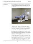
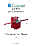
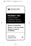
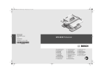
CS 810
Technical and User Manual
Cassese / Communication
FRAME ASSEMBLY MACHINE CS 810
SETTING UP FOR OPERATION
– The CS810 machine operates just with compressed air – minimum pressure 7,5 bars.
(110 p.s.i.)
– Adjust the machine to the desired working height or to the height of your work
table, by screwing the 4 threadet rods (M) up or down, not forgetting to fix the
locking nuts after each adjustment.
OPERATION
I. Connect your compressed air supply to the snap-connector inside the machine by the
air gauge.
II. Open the air supply by sliding upwards the black knurled sleeve above the air
connector, and check that the air gauge read at least 7,5 bars (110 p.s.i.) if not
regulate the pressure by lifting and turning the black cap on top of the filter
which is nest to the airline connector.
III. Loading/changing wedges
Use the black ball to pull back the slide, and lock it by pulling the ball upwards.
After putting the cartridge in place, unlock the slide by pulling down on the ball
and releasing slowly.
IV. Setting the Horizontal Clamp (D)
1) Standing in front of the machine, release the clamp (D) by unlocking handle (I).
2) Place a mitred piece of the moulding to be joined in position against the left
hand fence (C).
3) Flip up to horizontal position the adjustment lever (H), and push the clamp (D)
forward until it touches the moulding.
4) Lock the handle (I).
5) Push down the adjustment lever (H). This will give sufficient space for
mouldings to be slide into place between the clamp and the fence.
J
K
B
N
E
A
F
C
G
A
H D
O
P
I
L
M
1
V. Positioning the wedges
Pushing or pulling the uprights supporting the crossbar alters the position of the wedges which come
up through distributor head (G). With the piece of mitred moulding still in position slide the crossbar so that the
V-slit in the distributor head (G) is in the correct position for the rear wedge. Tighten the rear handle (L)
against the back of the crossbar upright. If only one wedge position is needed tighten front handle (L) also
against crossbar upright.
If 2 wedge positions are needed, move crossbar to forward position, and then tighten front handle (L).
To save some time the plunger run can be closed by the stop (J).
VI. Limiting plunger travel
For series production plunger travel can be restricted to suit height of the moulding by means of the handle (J).
METHOD OF JOINING
– Slide the first piece of moulding between the L.H. fence (C)
when working from the front, or R.H. fence (C) when working
from the back of the machine, and the clamp (D) until it touches
the opposite fence (‘see Fig. U
- Slide the second piece between the other fence and the clamp
until it touches the first piece.
– Depress the foot pedal to activate the clamp. With the pedal
still depressed, press the button (F). Every time the button is
depressed, the hold down plunger (E) descends and at the same
time a wedge is driven up.
By pressing the button twice on wedge can be driven on top of
another.
Note : the button only becomes live when the foot pedal is depressed.
H
C
D
TILTING OF FENCES (C)
– If the mitre joint is open on top
rotate both knobs (A) an equal amount
towards ( - )
open on top
open at the bottom
– If the joint is open at the bottom,
rotate both knobs (A) an equal amount
towards ( + )
ADJUSTMENT OF DRAFT ANGLE
On wide mouldings it is often advisable to increase the mitre angle slightly to draw the front of the
mitre joint together. The angle of the fences can be adjusted by rotating the knurled ring (B). When the two
scribe marks on top of the L.H. fence (C) coincide, the fences are at exactly 90°.
USE OF SPACER BARS –
When the height of the moulding is lower than the height of’ the fences (approx. 21mm) (13/16") the
spacer bars must be used so that the plunger (E) is not obstructed by the fences.
Place it on the table against the fence.
HOLD-DOWN PLUNGER (E)
– This is cylindrically shaped with a chamfered
base, which is covered with a circular pad of
plastic, larger in diameter than the base.
This ensures that the chamfered edge does not
mark the moulding.
E
Wooden spacer
– Figure III illustrates this as well as the way
which wedges are fixed in two different
positions and/or driven on top of each other.
Fig. III
(only for softwood).
– Important
Never cover the base of the plunger with felt, rubber or any other compressable material, because the
moulding will lift as the wedge is being driven in, and hence not be fully inserted.
MAINTENANCE
Changing the Hammer (fig. IV)
(The hammer is the piece which drives the wedges through the distributor head G
– Shut off air supply.
– Remove the air pipes fitted to the hammer drive cylinder (a).
– Release the cylinder support plate by removing the 2 screws (b).
– Free the hammer by pulling the cylinder assembly down.
– Remove the hammer by unscrewing the pin (c).
– Fit new hammer, ensuring the stub of pin (c) is correctly engaged in the hole of the hammer. Then
tighten the lock nut.
– Refix cylinder assembly with the 2 screws (b) and refit air pipes.
Hammer
C
Fig. IV
b
b
a
Distributor Head (G)
– Daily: before using the machine and each morning spray the area of the distributor head with a silicone spray.
This will make it easier to remove any accumulations of glue at the end of each day.
– Weekly: Loosen grub screw and remove distributor head (G). Clean the head and the area underneath using
a dry small hard brush. Never use any dry cleaning or other fluid.
3
Fig. V
ADJUSTING THE PLUNGER SPEED (E)
The knurled knob found of the cover (N)
controls the downward speed of the
plunger. When operating correctly the
plunger must descend before the wedge
is driven in.
This adjustment is set at the factory.
However, should it become necessary to
make an adjustment this is done with
a screwdriver acting on the time-lag
logic relay (T), found inside the machine
on the logic board. (see Fig. V)
T
IMPORTANT
THE- MACHINES BEING ADJUSTED IN OUR WORKSHOPS,
PLEASE DO NOT INTERFERE ON PARTS WHICH ARE NOT MENTIONED ON THESE
DIRECTIONS. WE DECLINE ALL RESPONSIBILITY IN CASE OF AVERAGES WHICH
WOULD BE DUE TO THE NONCOMPLIANCE WITH THIS ADVICE.
FAULT
Clamp: (D) fails- to grip tightly
REMEDY
- Reset the clamp as in para. IV of
Operation Instructions and
ensure handle (I) is tightly
locked.
Wedges protrudes from bottom of moulding.
– Air supply pressure is below 7,5
bars (110 p.s.i.).
– Moulding is not flat on the table.
– Faulty hammer.
Plunger marks the moulding.
– Self adhesive plastic pad on
bottom of plunger is worn out.
– The downward speed is too fast,
proceed to adjustment (see above).
– Moulding profile requires use of’
a wooden spacer (see page 3 –
fig.III)
Wedges do not protrude-.
– Cartridge is empty.
– Distributor is dirty, clean as
indicated in page 3 of Mainte
nance Instructions.
– Check the cartridge tension spring
– Hammer broken.
– Crossbar ( J ) is too forward.
Difficult to insert cartridges.
The wedge-driver does no function;
– The delay of the switch (see Fig.
V) is too long.
4
CS 810
Manuel Technique et d’Utilisation
Cassese / Communication
ASSEMBLEUSE POUR CADRES CS 810
MISE EN SERVICE
L’ASSEMBLEUSE CS 810 fonctionne uniquement à l’air comprimé – pression mini 7 bars.
Placer la machine au niveau de votre table de travail par réglage des écrous sur les 4 tiges filetées ( M ), sans oublier de bloquer les contre écrous après la mise à hauteur.
FONCTIONNEMENT
Ouvrir le robinet d’alimentation d’air comprimé et vérifier si le manomètre indique au minimum 6 bars. Sinon régler la pression en agissant sur le bouton du détendeur (tirez vers le haut et
tournez).
Chargement des coins. A l’aide de la boule noire, tirer le coulisseau vers l’arrière et la bloquer
en tirant la boule vers le haut. Après avoir placé un chargeur, débloquer en tirant la boule vers le
bas.
Réglage du serrage horizontal :
l°) en se situant devant la machine, débloquer la griffe de serrage ( D ) en agissant sur la
manette ( Z ).
2°) placer une coupe de la moulure à assembler contre la butée d’appui de gauche ( C ).
3°) lever le levier d’ajustement ( H ) de la griffe ( D ) et pousser l’ensemble vers l’avant
jusqu’au contact de la moulure.
4°)bloquer la manette ( I ).
5°) rabattre le levier d’ajustement ( H ). Vous avez à ce moment un jeu suffisant pour l’introduction des moulures le long des butées d’appui ( C ).
Positionnement des coins: s’effectue par les manettes ( L)
Réglage du presseur ( E ) : Pour le travail en série, la course du presseur peut être limitée en
fonction de la moulure à assembler en utilisant la butée ( J ).
J
K
B
N
E
A
F
C
G
A
H D
O
P
I
L
M
1
ASSEMBLAGE
Placez un premier coté du cadre à assembler devant la
butée et le faire glisser de façon à appuyer sur l’autre
butée ( voir fig 1 )
Placez le deuxième côté devant l’autre butée ( C ) en
contact du premier.
Appuyer sur la pédale pour obtenir le serrage.
Tout en maintenant l’action sur la pédale, appuyez sur le
bouton de commande ( F ).
Chaque sollicitation du bouton ( I ) déclenche le serrage
vertical (presseur E ) et la sortie simultanée d’un coin.
Il est possible de superposer 2 coins en sollicitant une
seconde fois le bouton de commande ( F ). Dans ce cas
ne pas interrompre l’action sur la pédale.
Le serrage vertical et l’insertion du coin ne peuvent être
effectués que si la pédale est maintenue appuyée.
H
C
D
ouvert dessus
INCLINAISON DES BUTEES ( C )
Si l’assemblage est ouvert dessus, il faut agir
en tournant d’une même quantité les deux boutons de réglage ( A ) dans le sens – :
Si l’ assemblage est ouvert dessous, il faut agir
en tournant d’une même quantité les deux boutons de réglage ( A ) dans le sens + :
ouvert dessous
REGLAGE RAIDE
Le «raide» s’obtient en augmentant légèrement l’angle de coupe des moulures, ce qui amène a
l’assemblage un serrage sur intérieur des joints du cadre.
On obtient un angle de 90° lorsque les deux traits coïncident ; en vissant le bouton moleté (B)
l’angle de 90° augmente.
UTILISATION DES BARRETTES LATERALES
Elles se placent devant les butées ( C ) pour dégager le presseur ( E ) lorsque la moulure à
assembler est de hauteur inférieure a celle des butées ( C ).
CHOIX DES COINS EN FONCTION DES MOULURES A ASSEMBLER
Utiliser un coin de hauteur inférieure de 2 mm à la hauteur de la moulure.
Augmenter cette garde en conséquence s’il s’agit de moulure avant une forte épaisseur de
blanc.
La figure III montre un exemple d’assemblage en 2 points avec coins superposés où le décalage
en hauteur entre les 2 points d’assemblage est supérieure à 20 cm.
2
PRESSEUR VERTICAL ( E )
Il est de forme cylindrique et comporte un chanfrein à sa
Fig. III
base.
Celle-ci est recouverte d’une rondelle en plastique de
diamètre supérieur lui donnant une certaine souplesse le
E
long du chanfrein ce qui évite de marquer la moulure.
Si la moulure est fragile ou si, en raison de son profil,
Cale en bois
l’utilisation du presseur ( E ) pose des problèmes, on place
une cale intermédiaire en bois sur l’angle à assembler.
Le Presseur vient en contact sur la cale permettant l’insertion
du ou des coins à l’arrière de la moulure et, du ou des coins à
l’avant de celle-ci bien que la cale ne soit pas en contact avec
la moulure dans cette dernière position ( fig III )(seulement
pour les bois tendres).
Important
NE JAMAIS RECOUVRIR LE PRESSEUR ( E ) DE FEUTRE, CAOUTCHOUC OU AUTRE
MATIÈRE SOUPLE PARCE QUE LA MOULURE SE SOULEVERAIT AU MOMENT DE
L’INSERTION DU COIN ET CELUI-CI NE PÉNÉTRERAIT PAS ENTIÈREMENT.
MAINTENANCE
Changement du marteau (fig. IV) (pièce qui pousse les coins à travers la tête du distributeur).
fermer le robinet d’alimentation
Enlever les tuyaux d’alimentation du vérin d’agrafage ( a ) .
Démonter la plaque support du vérin ( a ) en dévissant les 2 vis (b ) .
Dégager le marteau en tirant l’ensemble vers le bas .
Changer le marteau en prenant soin de bien engager le téton ( c ) de la vis de retenue dans le trou
de marteau et rebloquer ensuite l’écrou .
Remonter l’ensemble en remettant en place les 2 vis ( b ).
Marteau
C
Fig. IV
b
b
a
Entretien de la partie «Distribution d’agrafes»
Périodiquement démonter la tête du distributeur et nettoyer avec un pinceau à poils raides et à
sec toute la partie en contact avec l’avant du magasin d’agrafes.
3
Réglage de vitesse du presseur ( E )
La vitesse de descente du presseur est
réglable par le bouton moleté situé sur
la face avant du capot (N). Pour obtenir
un fonctionnement correct, il faut que
la descente du presseur précède le
déclenchement au marteau. Ce réglage
est fait par nos soins.
Toutefois en cas de besoin il faut agir
à l’aide d’un tournevis sur la cellule
temporisée (T) située a l’intérieur de la machine sur le circuit imprimé.
T
IMPORTANT
LES MACHINES ETANT REGLEES DANS NOS ATELIERS, IL EST RECOMMANDE
DE NE PAS INTERVENIR SUR LES PARTIES QUI NE SONT PAS MENTIONNEES SUR
CETTE NOTICE.
NOUS DECLINONS TOUTE RESPONSABILITE EN CAS D’AVARIES QUI SERAIENT
IMPUTABLES A L’INOBSERVATION DE CETTE RECOMMANDATION .
DEFAUT OU PANNE
CAUSE OU REMEDE
Le serrage de la moulure est insuffisant
Refaire le réglage et s’assurer que la
manette (I ) est insuffisamment bloquée.
Pression d’alimentation inférieure à 6
bars.
Moulure mal plaquée sur la table.
Marteau défectueux.
La rondelle plastique autocollante est
usée.
La vitesse de descente est trop rapide,
procéder au réglage. (Voir ci-dessus)
Baguette ayant un profil non compatible
avec la forme du presseur. Utiliser la
cale en bois. (voir page 3 – fig. III )
Chargeur vide.
Distributeur d’agrafes encrassé, faire
le nettoyage (voir entretien)
Vérifier l’état du ressort de tension
d’agrafe.
Le marteau est cassé.
La butée (L) empêche le recul de la potence ( J ).
La temporisation par la cellule est trop
importante (voir Fig. V).
L’agrafe ne s’enfonce pas entièrement
Le presseur marque la moulure
Les agrafes ne sortent pas
Difficultés pour introduire le magasin
Le vérin d’agrafage ne fonctionne pas
4