1
SEIKAKU TECHNICAL GROUP LIMITED
TOPP PRO
NF02447
/
TMW-8000R/T/P TOPP PRO_V1.0
PE02352
0.09Kg/1
105g
A3
A4
A5
16
MAY.25.2006
PHFWA102-20060200033,A,1
PGBSC001-200511001728
,
.
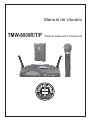
User's Manual
TMW-8000R/T/P
PROFESSIONAL WIRELESS SYSTEM
Fuse
SAFETY RELATED SYMBOLS
RISK OF ELECTRIC SHOCK
DO NOT OPEN
This symbol, wherever used, alerts you to the presence of un-insulated and dangerous voltages within the product enclosure. These are voltages that
may be sufficient to constitute the risk of electric
shock or death.
Before turning the product ON, make sure that it is
connected to Ground. This is to prevent the risk of
electric shock.
This symbol, wherever used, alerts you to important operating and maintenance instructions.
Please read.
Never cut internal or external Ground wires. Likewise,
never remove Ground wiring from the Protective
Ground Terminal.
Protective Ground Terminal
Operating Conditions
AC mains (Alternating Current)
Always install in accordance with the manufacturer's
instructions.
Hazardous Live Terminal
ON:
Protective Ground
To avoid the risk of electric shock and damage, do
not subject this product to any liquid/rain or moisture.
Do not use this product when in close proximity to
water.
Denotes the product is turned on.
OFF: Denotes the product is turned off.
WARNING
Describes precautions that should be observed to
prevent the possibility of death or injury to the user.
CAUTION
Do not install this product near any direct heat source.
Do not block areas of ventilation. Failure to do so
could result in fire.
Keep product away from naked flames.
Describes precautions that should be observed to
prevent damage to the product.
Disposing of this product should not be
placed in municipal waste and should be
Separate collection.
IMPORTANT SAFETY INSTRUCTIONS
Read these instructions
Follow all instructions
Keep these instructions. Do not discard.
Heed all warnings.
WARNING
Only use attachments/accessories specified by the
manufacturer.
Power Supply
Ensure that the mains source voltage (AC outlet)
matches the voltage rating of the product. Failure
to do so could result in damage to the product and
possibly the user.
Power Cord and Plug
Do not tamper with the power cord or plug. These are
designed for your safety.
Unplug the product before electrical storms occur
and when unused for long periods of time to reduce
the risk of electric shock or fire.
Do not remove Ground connections!
External Connection
Protect the power cord and plug from any physical
stress to avoid risk of electric shock.
Always use proper ready-made insulated mains
cabling (power cord). Failure to do so could result
in shock/death or fire. If in doubt, seek advice from
a registered electrician.
Do Not Remove Any Covers
Within the product are areas where high voltages
may present. To reduce the risk of electric shock do
not remove any covers unless the AC mains power
cord is removed.
Covers should be removed by qualified service
personnel only.
No user serviceable parts inside.
1
If the plug does not fit your AC outlet seek advice from
a qualified electrician.
Do not place heavy objects on the power cord. This
could cause electric shock or fire.
Cleaning
When required, either blow off dust from the product
or use a dry cloth.
Do not use any solvents such as Benzol or Alcohol.
For safety, keep product clean and free from dust.
Servicing
Refer all servicing to qualified service personnel only.
Do not perform any servicing other than those instructions contained within the User's Manual.
ENGLISH
CAUTION
To prevent fire and damage to the product, use only
the recommended fuse type as indicated in this
manual. Do not short-circuit the fuse holder. Before
replacing the fuse, make sure that the product is
OFF and disconnected from the AC outlet.
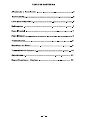
TABLE OF CONTENTS
1. WARNINGS AND INSTALLATION ............................................................................................................................................. 3
2. INTRODUCTION ......................................................................................................................................................................... 4
3. GETTING STARTED ....................................................................................................................................................................6
4. THE RECEIVER ......................................................................................................................................................................... 7
4.1 FRONT PANEL ................................................................................................................................................................... 7
4.2 REAR PANEL ..................................................................................................................................................................... 7
5. THE TRANSMITTERS ................................................................................................................................................................ 8
5.1 HANDHELD MICROPHONE ...............................................................................................................................................8
5.2 BODYPACK ....................................................................................................................................................................... 9
6. CONNECTIONS ..........................................................................................................................................................................10
7. TECHNICAL SPECIFICATIONS ................................................................................................................................................ 12
2
1. WARNINGS AND INSTALLATION
Switching on and off
CAUTION: before switching on or off, make certain the sound system's amplifiers are off: this will avoid signal peaks,
which are annoying and sometimes dangerous (particularly for speaker enclosures).
Connecting and preventing or identifying interference
First of all, check that the apparatus is installed in a place free from industrial or RF (radio frequency) interference.
Avoid installing your equipment very near radio or TV sets, mobile phones, etc., as these can cause noisy interference.
When connecting the other parts of your sound system, watch out for the so-called "round loops", which could cause
hum and jeopardize the products's excellent Sound-to-Noise and low distortion characteristics. The best way (even
if not always feasible) to avoid ground loops is to connect the electric ground of all the equipment to a single central
point ("star" system). In this case, the central point can be the mixer.
Protection and maintenance
Don't force knobs or switches: these are designed and manufactured to respond to light pressure and could be
damaged if used with excessive force.
Take care of your connector cables, a very frequent cause of small/big problems. Always grip them by the connector,
avoid pulling them forcefully and wind them without forming knots or sharp bends: they'll last longer this way, and be
more reliable, which is a definite advantage.
Avoid exposing the product to strong direct sunlight, high temperatures or intense vibrations, in very dusty or particularly
damp surroundings or, even worse, in the rain: this will help to avoid the risk of faulty operation, deterioration or even
electric shocks and fires.
The product is built in shock-resistant material. Nevertheless, protect it during transport with a flight-case to avoid the
risk of any casual accidents.
When you've finished using the apparatus, it's always advisable to protect it from dust, but any dust that does form
should be removed using a cloth or a soft brush. Never use alcohol, acetone or any solvents. The unit does not
require any other maintenance.
In the event of breakdown
All user-adjustable parts are external and easily accessed.
In the event of a breakdown, do not open the apparatus, but contact the nearest TOPP PRO Service Centre.
3
ENGLISH
Connection to the mains supply
The unit is supplied with an external power supply. Before switching on the unit, make certain that the mains voltage
matches that shown on the power supply (a tolerance of up to ±10% is acceptable).
2. INTRODUCTION
TMW-8000R/T/P is an efficient, high-quality wireless microphone system, with a user-friendly control set. The use of
the UHF band (780-865MHz) enables the majority of interference problems afflicting lower bands to be overcome.
Shorter waves are less susceptible to reflection, so they tend to saturate the area around the transmitter better. The UHF
band is therefore more suited to critical situations (stages or clubs with a lot of lights and amplifiers) where reflections
can cause problems for VHF sound waves.
The transmitter/receiver frequency has been pre-set on our premises and it is showed:
on the products package;
on the rear panel of the receiver;
on the battery space inside the hanheld microphone;
on the back of the bodypack transmitter.
The TMW-8000R/T/P receiver has two antennas and it makes use of the SWITCHING DIVERSITY technology. This
technology enables greater reliability and coverage than single antenna systems. In real time, the circuitry automatically
selects the antenna receiving the best signal, reducing breakdown and interference risks. Switching between the two
antennas, controlled by an opto-coupler, is immediate and totally noisefree.
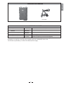
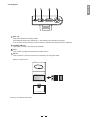
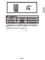
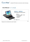
The system TMW-8000R/T/P comprises a receiver and transmitters.
RECEIVER
HANDHELD MICROPHONE
4
BODYPACK with LAVALIER
ENGLISH
LM-10 (4B)
SERIES TMW-8000R/T/P
Component
Description
Name
Receiver
TMW-8000R
UHF SWITCHING DIVERSITY receiver
Handheld microphone
TMW-8000T
UHF Handeld microphone
Bodypack transmitter
TMW-8000P
UHF Bodypack transmitter
Lavalier microphone
LM-10 (4B)
Lavalier microphone (to be used with bodypack)
The transmitters are powered by normal alkaline batteries. The circuitry has been designed to reduce current
absorption to a minimum, ensuring longer operating times at considerably lower costs.
The receiver is powered by a normal 12V external power supply.
5
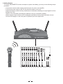
3. Getting Started
To use the TMW-800R/T/P wireless microphone system immediately, just carry out the following simple
procedure:
Connect the receiver audio output to the line input of a mixer or an amplifier.
Connect the power supply to the DC IN socket and switch on the unit.
Adjust the Squelch control until any interference is eliminated, obtaining an output signal free from
background noise.
Switch on the transmitter (first fitting the batteries if they're not already installed).
Adjust receiver output volume and (if a bodypack transmitter is being used) transmitter volume.
Use the LED displays on the front panel to optimize input and output levels.
6
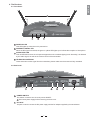
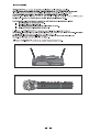
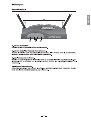
4. The Receiver
ENGLISH
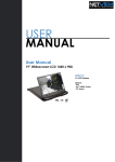
4.1 Front Panel
4
45
45
1
2
3
1 POWER ON LED
This LED lights up when the unit is powered on.
2 DIVERSITY SIGNAL LED
When the RF signal is received, the green or yellow LED lights up to indicate the reception of microphone.
3 AUDIO PEAK LED
This red LED blinks when the microphone approaches the overload clipping level. Generally, it is affected
by the audio signal, as well as the volume control of the transmitter.
4 TELESCOPIC ANTENNA
These antennas receive signal from the transmitter, please make sure the antenna is fully extended.
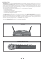
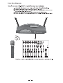
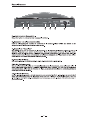
4.2 Rear Panel
5
5
6
7
8
9
10
POWER SWITCH
This switch is used to turn the main power ON/OFF.
Disconnect power supply before removing receiver cover.
6
DC JACK
This jack is used to connect the DC power supply with the DC adapter supplied by the manufacturer.
7
7
SQUELCH CONTROL
This control is factory preset for adjusting SQ noise. If you find the receiver already has been jammed by
outside signal, please adjust SQ control till the jamming signal disappears before you turn on the
microphone power switch. (Counterclockwise)
8
VOLUME CONTROL
This control can adjust the audio output level from the wireless system.
9
AUDIO OUTPUT CONNECTOR
This connector is used to connect the inputs of the mixer or power amplifier etc.
10 BALANCE SOCKET
This socket is used to connect the inputs of the mixer or power amplifier etc.
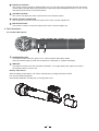
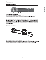
5. The Transmitters
5.1 Handheld Microphone
1
2
1
POWER SUPPLY LED
This LED indicates when the power is on, it also indicates the battery status.
If the LED doesn't light up when the microphone is switched on, replace the battery.
2
SWITCH
This switch is used to turn the microphone ON/OFF. For longer battery life, please turn off the
microphone when it is not in use.
Battery replacement
When installing a new battery, turn off the microphone by setting the switch at OFF.
Use only 9V alkaline batteries.
Good quality batteries normally last on average 6-8 hours.
8
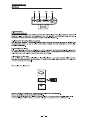
5.2 Bodypack
2
3
4
1 BAT. LO
This LED indicates the battery status.
If this flashes briefly when switching on, the batteries are sufficiently charged.
If on the other hand it remains lit, this means the batteries are flat and must be replaced.
2 POWER ON/OFF
This switch is used to turn the power ON/OFF.
3 VOL.
This control can adjust the transmitter output volume.
4 MIC IN
This connector is used to connect the microphone or the guitar cable.
Battery replacement
Use only 9V alkaline batteries.
9
ENGLISH
1
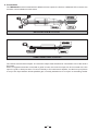
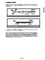
6. Connections
The TMW-8000R receiver is fitted with two different format outputs: the first has a balanced XLR connector, the
second a normal unbalanced Jack socket.
BALANCED XLR-M connector
UNBALANCED JACK connector
The receiver has line-level outputs. The receiver's output must therefore be connected to one of the mixer's
line inputs.
When a bodypack transmitter is used with a guitar or bass, the receiver's output can be connected to the line
input of a guitar or bass processor. To connect directly to the instrument's amplifier, use the line input (if there
is one) or the input with the lowest possible gain, normally indicated as "Low Input" or something similar.
10
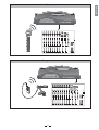
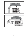
Handheld Microphone Connection
ENGLISH
Bodypack Connection
11
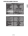
7. Technical Specifications
TMW-8000R Receiver
Reception mode
Diversity model
Carrier Frequency Range
UHF 780 ~ 865 MHz
Oscillation Mode
Quartz controlled fixed frequency
Stability
0.005% /25 C
Max. Deviation
40 / 55 KHz
Dynamic Range
> 110dBm
S/N Ratio
> 100dB At
T.H.D.
< 0.6%
Squelch
Tone Key (Tone frequency : 32.768KHz)External Control
Frequency Response
50Hz - 15KHz 3dB
Sensitivity
3uV for 20dB SINAD
Audio Output
Power Supply
1. Unbalanced 6.3mm phone jack 750mV/5K 2. XLR Balanced output 60mV/600
DC 12V-15V 300mA with AC/DC Adaptor
Dimensions
295(W) 114(D) 40(H) mm
Weight
550g / 1.21 lb
15KHz Deviation
0.97(W) 0.37(D) 0.13(H) ft
TMW-8000T Handheld Microphone
Carrier Frequency Range
UHF 780-865 MHz
Microphone Element
Dynamic Microphone
Oscillation Mode
Quartz controlled fixed frequency
Modulation mode
FM (F3E)
Antenna
Built-in
RF Carrier Power
10mW (may be adjusted bassed on regulation)
Effective Radiated Power (Spueious)
Less than 2mW
Tone Frequency
32.768KHz
Pre-Emphasis
50uS
Current Drain
35mA Typical(9.0V)
Battery
More than 8 hours (Alkaline)
Dimensions
246mm/9.69(H)"
Weight
Approx. 0.21kg/0.46(lb)
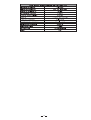
TMW-8000P Bodypack Transmitter
Carrier Frequency Range
UHF 780-865 Mhz
Oscillation Mode
Phase Locked Loop System
Modulation mode
FM (F3E)
Antenna
Built-in
RF Carrier Power
5mW
Power Source
DC + 9V
Tone Frequency
32.768KHz
T.H.D
1%
Current Drain
35mA Typical
Battery
More than 8 hours (Alkaline)
Dimensions(L x W x H)
106 23 66 mm/4.17(L)" 0.91(W)" 2.60(H)"
Weight
Approx. 80g(0.177lbs)
12
Manual de Usuario
TMW-8000R/T/P
Sistema Inalambrico Profesional
PRECAUCION
NO ABRIR,
PELIGRO DE
GOLPE ELECTRICO
SPANISH
1
2
SPANISH
3
RECEIVER
HANDHELD MICROPHONE
4
BODYPACK with LAVALIER
5
SPANISH
LM-10 (4B)
6
45
45
1
2
3
7
SPANISH
4
5
6
7
8
8
9
10
SPANISH
2
1
9
1
2
3
10
4
SPANISH
BALANCED XLR-M connector
UNBALANCED JACK connector
11
Handheld Microphone Connection
Bodypack Connection
12
SPANISH
13
14
SPANISH
15
NF02447-1.0