1
optiMOS USER MANUAL
CHAPTER 3
USING YOUR optiMOS CAMERA
Imaging Software
The QImaging optiMOS camera is supported in a multitude of software applications including Micro-Manager.
For an up-to-date list of compatible third-party imaging software applications, please visit:
http://www.qimaging.com/resources/pdfs/Software-Compatibility-Matrix.pdf
The optiMOS camera’s image capture capabilities are controlled entirely through the imaging software. Basic
functionalities include control over exposure time, region of interest (ROI), sequence size, time-lapse delay, and
hardware triggering modes. For information describing how to implement changes to the camera’s parameters,
refer to your imaging software’s instruction manual.
Basic Camera Parameters
Exposure Time
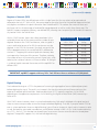
The optiMOS camera’s exposure controls allow you to adjust the integration time for each acquisition
(0ms – 30s). By increasing the exposure time, more light is captured by the sensor and a better signal-to-noise
ratio (SNR) is achieved. The longer the exposure time however, the longer you also expose your cells to more
light, increasing the effects of photo toxicity and photo-bleaching. The exposure time should be adjusted to a
level that achieves the shortest integration time possible while still maintaining sufficient SNR.
Rolling Shutter
Image sensors typically operate in one of two readout modes: Global Shutter or Rolling Shutter. Traditional
CCD cameras use a global shutter mode where every pixel exposes at the same instant in time and is then
digitized in sequence by a single ADC. This has the advantage of minimized spatial distortion across the entire
frame and is the only readout mode supported by most CCD cameras. The single ADC however, is also an
inherent disadvantage as it significantly limits the maximum frame rates of the camera.
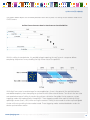
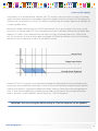
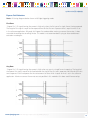
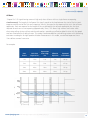
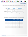
CMOS sensors however are able to achieve much higher frame rates by employing a Rolling Shutter readout
mode. In this mode, each column of pixels has its own ADC that digitizes the collected signal one row at a time.
Because of this, each row of pixels begins exposing one line’s readout time after the previous row’s start. This
line time is based on the sensor’s clocking requirements and readout frequency. For the optiMOS at 283MHz, a
single line’s readout time and consequently, the delay between two adjacent rows is approximately 8.7us. With
1,080 rows of pixels, the time delay from the top to the bottom of the sensor is approximately 10ms, which also
corresponds to the maximum frame rate of 100fps and minimum temporal resolution of 10ms (at full frame).
www.qimaging.com
©2014 QImaging. All rights reserved. QI_OPTIMOS_UM_Rev_A1
9