1
Chapter 2
ft
Software Defined Radio
Architecture
D
ra
A SDR is a real-time system. The inputs to the system are actions performed by
the radio operator and data produced by active elements present in the SDR,
such as analog to digital converters. The outputs are graphical depictions of
the radio and digital representations of radio and audio signals. To prevent
undesirable effects, such as flickering or chopping, the outputs must be produced promptly and consistently with the inputs. Outputs must be generated
to provide an effect of continuity to the radio operator, even though the SDR
is functioning according to a discrete model. Real-time performance is achieved
by a combination of hardware resources and a carefully designed software architecture. This chapter introduces the reader to the concepts used to deal
with the complexity and structure of SDRs, i.e., the architecture of SDRs. This
chapter aims to provide a big picture of all the elements involved in the design
of SDRs. The hardware and software architectures of SDRs are discussed at
length. The hardware architecture is reviewed with examples in Section 2.1.
From Section 2.2, the emphasis is on software architecture. Both high level
design and detailed design are examined, with a discussion of SDR to computer
communications, in Section 2.3, and the structure of a signal processing block,
in Section 2.4.
2.1
Hardware Architecture
Since the early 2000s, the availability at reasonable cost of SDR platforms for
experimenters has considerably progressed. Such platforms are ideal for experimentation when the hardware and software are open. That is to say, when
hardware schematics are available and involved firmware and software are open
source. When these conditions are absent, then sooner or latter the experimenter faces obstacles hardly surmountable because of a lack of information.
When detailed hardware design and source code are available, everything can
31
© 2015 Michel Barbeau
Software Defined Radio
be understood. Any solvable problem can be solved! It is only a matter of time.
Two SDR platforms that meet these conditions are the Universal Software Radio Peripheral and High Performance Software Defined Radio. They are both
introduced hereafter. This section also includes an overview of SDRs used for
tactical communications.
Universal Software Radio Peripheral
ra
ft
2.1.1
D
Figure 2.1: The USRP.
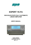
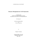
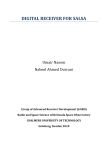
In this subsection, we review the hardware architecture of the Universal Software Radio Peripheral version 2 (USRP2) [14]. The USRP2 bridges the analog
world of electromagnetic radio waves and digital world of computers, on which
the actual processing of signals is done, e.g., demodulation and modulation.
The USRP2 is an independent hardware box connected to a computer using a
point-to-point network connection, actually an Ethernet cable. Figure 2.1 is a
photo of a USRP2 unit. Top-right, there is a SMA connector for the antenna,
with the label RF2. Below, there is a port for pluging in an Ethernet cable connecting the USRP2 unit to a computer. The hardware structure of the USRP2
is modular. It contains two main types of boards: a motherboard and one or
several daughter boards. The motherboard consists of two Analog to Digital
Converters (ADCs), two Digital to Analog Converters (DACs), Digital Down
32
CHAPTER 2. SOFTWARE DEFINED RADIO ARCHITECTURE
Software Defined Radio
© 2015 Michel Barbeau
ra
ft
Converters (DDCs), Digital Up Converters (DUCs), an interconnection unit and
a network interface.
There are two ADC input channels. Each ADC produces a stream of 14
bit-samples at a rate of 100 Mega samples per second (Msps). According to the
sampling theorem (sampling rate is twice the bandwidth), this means that the
ADC has a bandwidth of 50 MHz. The sampling is centered at the Intermediate
Frequency (IF) of an analog radio receiver connected to the input of the ADC.
The ADC maps the sampled bandwidth to the range -25 MHz to 25 MHz.
There are two DAC output channels. Each DAC accepts a stream of 16 bitsamples at a rate of 100 Msps, also corresponding to a bandwidth of 50 MHz.
The DAC produces the IF signal for the analog radio transmitter connected to
its output.
The input channels are paired together to carry the in-phase and quadrature
of the same signal, likewise for outpout channels. In other words, the USRP2
has one input complex signal channel with a bandwidth of 50 MHz and one
output complex signal channel also with a bandwidth of 50 MHz. The network
interface, a Gigabit Ethernet port, insures the communications between the
USRP2 unit and computer. There is a flow of frames containing samples from
the USRP2 to the computer and another flow of frames loaded with samples
from the computer to the USRP2 unit. The interconnection unit contains a
multiplexor and a demultiplexor. On the input channel, there is a DDC. The
DDC performs decimation of the sample stream. Decimation reduces the rate
of the stream by a selectable integer factor m. In the stream, only every mth
sample is retained. The others are dropped. Effectively, decimation has a low
pass filtering effect and reduces the bandwidth of the signal by the same factor
m. The resulting decimated signal is still centered at zero Hz. The highest
frequencies are filtered out.
Exercise 2.1
D
Using decimation, the DDC reduces, by a factor m, the data rate of the input
channel (originally at 100 Msps). What is the bandwidth of the signal produced
by the DDC?
On the output channel, there is a DUC. By interpolation, it increases the
date rate, by a selectable factor m. New m − 1 sample values are inserted
between every mth sample from the original stream. Their value is estimated.
The DUC maps a baseband signal to the DAC input rate (i.e., 100 Msps).
The USRP2 unit has two slots for pluging in daughter boards. One of
them is for a radio frequency transmitter and the other is for a radio frequency
receiver. The receiver is connected to the two ADCs. Similarly, the transmitter
CHAPTER 2. SOFTWARE DEFINED RADIO ARCHITECTURE
33
Software Defined Radio
ra
ft
© 2015 Michel Barbeau
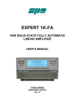
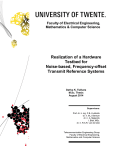
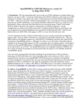
Figure 2.2: A USRP2 unit with TVRX daughterboard.
D
is connected to the two DACs. Figure 2.2 shows a photo of a USRP2 unit with
the top cover removed. The TVRX daughterboard is mounted. It is a receiver,
originally designed for TV sets, covering from 50 MHz to 860 MHz. The actual
signal bandwidth is six MHz, much lower than the 50 MHz that can be handled
by the USRP2.
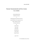
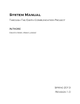
The flow of an input signal in a USRP2 unit is pictured in Figure 2.3.
The signal flows from left to right. An antenna captures the electromagnetic
signal. A receiver converts the electromagnetic analog signal into an electric
analog signal at the IF. Two ADCs convert the IF analog signal into a digital
representation, i.e., two streams of samples. Each stream is at 100 Msps, 14 bits
per sample. One branch produces the in-phase signal while the other outputs
the quadrature signal. The bandwidth of the signal is centered at zero Hz and
spans from −25 MHz to 25 MHz. The DDCs reduce both the sample data rate
and bandwidth by a factor m. The bandwidth of the resulting signal is also
centered at zero Hz and spans from −25/m MHz to 25/m MHz. The samples
are then buffered and sent to the computer using an Ethernet (ETH) network
interface. The flow of an output signal is similar. In Subsection 2.2, we carry
on with the architecture of software for the USRP2.
34
CHAPTER 2. SOFTWARE DEFINED RADIO ARCHITECTURE
© 2015 Michel Barbeau
ft
Software Defined Radio
Figure 2.3: USRP2 input signal flow.
Exercise 2.2
ra
Assuming that four bytes are required to represent every signal sample (two
bytes for the in-phase and two bytes for the quadrature) and an overhead of
approximately 20% is needed (for headers and control signals), estimate the
maximum data rate needed to support the communications between a USRP2
unit and a computer. Redo the same calculations, assuming a sample rate of
250 Ksps.
2.1.2
High Performance Software Defined Radio
D
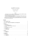
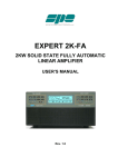
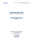
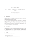
Figure 2.4 shows a High Performance Software Defined Radio (HPSDR) unit
with the top cover removed. The HPSDR is a modular system with several
possible configurations. Every module is named after a character of the Greek
mythology that evokes its function. This particular unit includes a Metis Ethernet interface, a Mercury receive module, a Penelope transmitter module (the
first three vertical cards), the Alex RF bandpass filters (grey module placed
right) and a PennyWhistle power amplifier (placed behind the vertical cards).
Using a Gigabit Ethernet link, the Metis interface insures the communications
between the HPSDR unit and a computer. Using a 130 Msps 16-bit ADC, the
Mercury receive module directly converts from analog to digital the zero to 55
MHz spectrum. A DDC reduces the sample rate to 192 Ksps (i.e., a bandwidth
of 96 KHz). The Penelope transmitter module converts signals from digital to
analog RF. It consists of a DUC and a DAC. The RF is in the 1.8 MHz to
55 MHz range at 500 milliwatts. It is very low power in the HF range. The
PennyWhistle power amplifier raises the level of the signal up to 20 watts. The
Alex RF bandpass filter, on the receive path, consists of high pass and low pass
CHAPTER 2. SOFTWARE DEFINED RADIO ARCHITECTURE
35
Software Defined Radio
ra
ft
© 2015 Michel Barbeau
Figure 2.4: The HPSDR with top cover removed.
D
hardware filters that select solely the signals falling within the HF amateur radio bands. The signals outside the HF amateur radio bands are attenuated. On
the transmit path, low pass filters attenuate the levels of the harmonics falling
outside the amateur radio bands.
Exercise 2.3
In a HPSDR system, there are four streams of samples. There are two 192 Ksps
streams representing the in-phase and quadrature of a received radio signal,
at 24 bits per sample. There are two 48 Ksps streams representing the inphase and quadrature of a transmitted radio signal, at 16 bits per sample. In
contrast to the USRP2, the HPSDR has an onboard mono ADC (connected
to a microphone) and an onboard stereo DAC (connected to a speaker). For
example, on the receive path the signal samples are sent from the HPSDR unit
to the computer. The signal is demodulated on the computer. The demodulated
audio is returned to the HPSDR for digital to analog conversion and speaker
output. That is to say, the audio is captured and rendered on the HPSDR unit.
36
CHAPTER 2. SOFTWARE DEFINED RADIO ARCHITECTURE
Software Defined Radio
© 2015 Michel Barbeau
Therefore, in addition to the two radio double signal streams there are two 48
Ksps streams for audio output and one 192 Ksps stream for audio input, at 16
bits per sample in all cases. Assuming that an overhead of approximately 20%
is needed (for headers and control signals), estimate the data rate required to
support the communications between a HPSDR unit and a computer.
Tactical Communications Systems
ft
2.1.3
D
ra
The coverage of the topic SDR hardware architecture wouldn’t be complete
without a look at some high end platforms. Although they may be not within
the means of the average experimenters, they do illustrate what the state of the
art is in this field. We introduce SDR systems used in tactical communications
systems, all featured radios are from Ultra Electronics. In all the models, the
computer and radio frequency hardware are integrated within the same unit.
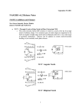
Figure 2.5 shows the AN/GRC-512A(V) Radio Relay [77]. This unit includes
Figure 2.5: The AN/GRC-512A(V) Radio Relay (Picture courtesy Ultra Electronics).
facilities for dealing with radio jamming (e.g., spectrum analysis and frequency
CHAPTER 2. SOFTWARE DEFINED RADIO ARCHITECTURE
37
© 2015 Michel Barbeau
Software Defined Radio
ra
ft
hopping), an important threat in tactical communications. The achievable data
rate is 4 Mbps, enough for digital voice. It operates in the 225 MHz to 440
MHz, 610 MHz to 960 MHz and 1.35 GHz to 1.85 GHz bands.
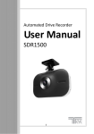
Figure 2.6: The AN/GRC-245A(V) HCLOS Radio (Picture courtesy Ultra Electronics).
D
Figure 2.6 pictures the model AN/GRC-245A(V) HCLOS Radio [76]. HCLOS means High Capacity Line-Of-Sight Radios. It can operate in the 225
MHz to 440 MHz, 1.25 GHz to 2,69 GHz and 4.4 GHz to 5 GHz bands. Over
distances of up to 40 kilometers, it can achieve a data rate up to 34 Mbps.
This data rate is enough for real-time video streaming. It integrates networking
support, using the Internet Protocol. This unit is designed for reliability, very
robust and can sustain very harsh environmental conditions.
Figure 2.7 features the next generation HCLOS radio. It integrates features
of the two aforementioned models.
2.2
Software Architecture
This section is about the software architecture of SDR applications, both high
level and low level. The model-view-controller pattern, the foundation of several
software applications comprising a Graphical User Interface (GUI), is used and
discussed at length.
38
CHAPTER 2. SOFTWARE DEFINED RADIO ARCHITECTURE
© 2015 Michel Barbeau
ft
Software Defined Radio
ra
Figure 2.7: The next generation HCLOS Radio (Picture courtesy Ultra Electronics).
2.2.1
The Model-View-Controller Pattern
data
model
updates
controller
actions
D
updates
view
Figure 2.8: The MVC pattern.
We base the overall software architecture of a SDR on the Model-ViewController (MVC) pattern [73], see Figure 2.8. The elements of the resulting
code are easily identifiable. It is a pattern also adopted by most of the GUI
environments, although the exact terminology may vary. Generally speaking,
the model is a source of data, e.g., a table in a data base, a file or a system
variable. Data sources can be multiple. In a SDR application, the model consists of hardware component abstractions and software signal processing blocks.
The view is the GUI, e.g., a window. It is presented on a monitor. The view
contains buttons, to control the radio operation, and fields, to display the radio
frequency and other parameters. Views can be multiple. The controller insures
CHAPTER 2. SOFTWARE DEFINED RADIO ARCHITECTURE
39
© 2015 Michel Barbeau
Software Defined Radio
ft
the consistency between the model and view(s). The controller pulls data from
the model, e.g., the current frequency. It handles actions on the view (e.g.,
operator inputs). It updates the model (e.g., retune the radio) and view(s)
(e.g., update the current frequency) according to the information contained in
incoming data elements and actions. In other words, the controller is the SDR
main procedure.
We discuss hereafter the organization of a software application for the USRP.
The application is a FM receiver. It is assumed that the daughterboard TVRX2
50 to 860 MHz receiver is plugged into the receiver slot of the USRP. The
application runs on the computer connected with an Ethernet cable to the USRP
unit. The development is based in on the GNU Radio Application Programming
Interface (API) and framework [20]. Under the Linux operating system, this API
is available in the Python programming language. In the sequel, we outline a
typical architecture of an SDR application in that environment. We then walk
through the code of its detailed implementation in the Python programming
language.
Architecture Outline
ra
2.2.2
The architecture of the application software is according to the MVC concept.
It is a way to deal with complexity. It acknowledges and separates three aspects: the domain specific logic, GUI and flow of execution. Separate aspects
individually represent smaller problems that are easier to address and solve.
A MVC-based application is best programmed with code units directly corresponding to the three MVC aspects. The code is just easier to read, assuming
that the reader as a good grasp of the MVC pattern. In an object-oriented
language such as Python, each aspect may be coded as an individual top-level
class. The program is outlined as follows:
# Import the GNU Radio modules
import ...
D
class Model(superclass):
# The model of the application
# −−−−−−−−−−−−−−−−−−−−−−−−−−−−
i n i t (self):
def
# Constructor
# −−−−−−−−−−−
...
# Other methods ...
class View(superclass)
# The View of the application
# −−−−−−−−−−−−−−−−−−−−−−−−−−−
def
i n i t (self,ctrl,panel,mainbox):
# Constructor
# −−−−−−−−−−−
...
# Other methods ...
40
CHAPTER 2. SOFTWARE DEFINED RADIO ARCHITECTURE
Software Defined Radio
© 2015 Michel Barbeau
class Controller(superclass):
# The controller of the application
# −−−−−−−−−−−−−−−−−−−−−−−−−−−−−−−−−
i n i t (self,frame,panel,vbox,argv):
def
# Constructor
# −−−−−−−−−−−
...
# Other methods ...
ft
name
== " m a i n ":
if
# The main program
# −−−−−−−−−−−−−−−−
# Create the Controller
Controller()
# Repeat: Wait until an event and handle the event
D
ra
It is our first Python example. A introduction to Python can be found in
Appendix B. The code starts with import clauses that bring in code from
libraries used to build the application. There are normally imports specific to
the model, view and controller. One Python class is defined for each aspect
of the application, namely, Model, View and Controller. Every such class
may be built using a super class contained in one of the imported libraries.
Each class embeds a constructor, with the signature def init (self):. The
constructor is invoked automatically when an instance of the class is created.
The constructor of the model contains code that builds and initializes the data
and logic of the application. Likewise, the constructor of the view assembles and
starts the GUI. The code of the controller creates one instance of the model and
one instance of the view. The controller also registers, with the view, handlers
of events. Each event handler may be implemented as an individual method.
The registration typically involves binding an event handler to a GUI element,
called a widget. Hence, when this widget is activated, e.g., a button is pressed,
the corresponding event handler is invoked. Events may be registered in the
controller. When supported by the API, events handlers are registered when
each widget is created. The controller may need to invoke explicitly a method
to provoke the display of the view (not required in this example).
Every class may also enclose other methods needed for its implementation.
The main part of the program, delimited by the statement if name ==
" main ":, creates an instance of the controller and contains the main program loop. The loop is designed such that it repeatedly blocks and waits for
an event to occur. When an event occurs, the execution is transferred to the
corresponding handler. The code of the handler is run to completion, before any
other event is handled. If necessary, events may be queued. It is an event-based
execution model.
The complete Python code of the application can be found in Appendix C.
In the following three sections, we discuss some details of the implementation
of the three main classes.
CHAPTER 2. SOFTWARE DEFINED RADIO ARCHITECTURE
41
© 2015 Michel Barbeau
Software Defined Radio
The Model
ft
The model represents the data and logic of the application domain. The controller may perform updates on the model, such as changing the frequency.
Upon request, the model may return data elements to the controller, such as
the current frequency. In principle, the model should be independent of the
view and controller. On the other hand, the view is by nature dependent on the
model, while the controller depends on both the model and view.
Model
aDemodulator
aSoundCard
ra
anUSRP
Figure 2.9: Model of a SDR FM Broadcast Receiver.
D
The logical model of the SDR general coverage FM receiver, leveraging the
GNU Radio API and USRP SDR, is pictured in Figure 2.9. The radio is constructed according to a hierarchical flow graph model. The nodes of the graph
are signal-processing blocks. The links are data flows between signal processing
blocks. A flow graph has a source and a sink. Blocks have input ports and
output ports. Ports are typed; short, float or complex. Ports are connected together with links. In a general, a link is point-to-multipoint, i.e., an output port
can be linked to several input ports. Linked ports must all be of the same type.
The signal processing blocks are implemented in C++ libraries. The graph is
programmed in Python. The GNU Radio API includes glue code that bridges
the Python and C++ worlds. In Figure 2.9, the signal flows from left to right.
The node anUSRP represents the source of signal. For processing, the output
port of node anUSRP is connected to the input port of node aDemodulator. The
output port of node aDemodulator is connected to the input port of the node
aSoundCard. All three nodes are embedded in a super node of type Model.
This is translated in Python as a class named Model.
class Model (gr.hier block2):
Class Model is defined as a specialization of class hier block2, a kind of signal
processing block that can combine other blocks. The core of the logic of the
class Model is in method init . Let us look at the details of this method. To
perform complete initialization, the method starts with a call to the constructor
of the parent class.
42
CHAPTER 2. SOFTWARE DEFINED RADIO ARCHITECTURE
Software Defined Radio
def
© 2015 Michel Barbeau
i n i t (self):
gr.hier block2. init (self,
"General Coverage FM Receiver",
gr.io signature(0,0,0), # input signature
gr.io signature(0,0,0)) # output signature
ra
ft
Every block has a set of input streams and output streams. For a hierarchical
block, the input signature and output signature (gr.io signature(0,0,0) in
both cases) specify the number of input ports and number of output ports, and
their data type. For this block, there are none. It is solely a container.
The construction of the flow graph of the model starts hereafter. In this
example, there are only three nodes and one super node. Firstly, a source node
is created, named anUSRP, using the GNU Radio function uhd.usrp source.
The USRP unit is selected by IP address. The first argument of the function is
the IP address of the USRP unit. The second parameter is the data type of the
samples generated by the USRP unit, i.e., 32-bit float complex numbers. The
third parameter indicates that the USRP is the source of one stream of sample
numbers. The sample rate is set to 250 Ksps.
# USRP set up
self.anUSRP=uhd.usrp source(
device addr="addr=192.168.10.2", # hardware identity
io type=uhd.io type.COMPLEX FLOAT32, # input data type
num channels=1) # number of stream from the device
# Set the sample rate
self.anUSRP.set samp rate(250e3) # 250 Ksps
Secondly, using the function blks2.wfm rcv the demodulator is created, named
aDemodulator. The first argument is the input sample rate. The second number
is a decimation factor. This means that the sample rate at the output of the
demodulator is 15,625 sps (250 Ksps divided by 16). The bandwidth is lowered
to 7,812.5 Hz.
D
aDemodulator = blks2.wfm rcv(250e3, 16)
Thirdly, using the function audio.sink a sound card is instantiated. The sink
is named aSoundCard. The first argument is the input sample rate (in sps). The
second argument is the label of the sound card, default is used if left unspecified.
aSoundCard = audio.sink (15625, "")
Finally, the last step consists of interconnecting all together the nodes of the
flow graph.
self.connect (self.anUSRP, aDemodulator, aSoundCard)
CHAPTER 2. SOFTWARE DEFINED RADIO ARCHITECTURE
43
© 2015 Michel Barbeau
Software Defined Radio
The View
ra
ft
The view renders the graphical representation of the application and enables
interaction with the user. From the model, it gets and displays data elements.
There are clickable widgets. The view waits for user actions. When one occurs,
an event reflecting the action done by the user is generated.
Figure 2.10: General coverage FM receiver view.
D
The MVC view aspect is coded in Python as the class View. The constructor
method init has three formal parameters, in addition to a self reference.
The parameter ctrl is a reference to the controller of the application. The
parameter panel refers to a graphical area in which are placed the upcoming
widgets, see Figure 2.10. The parameter mainbox represents a panel layout
manager. By definition, the widgets are placed vertically one after the other.
The values of the formal parameters are stored in attributes. The constructor
transfers the control to method BuildGui().
def
i n i t (self,ctrl,panel,mainbox):
# Constructor
# −−−−−−−−−−−
# Store parameters into attributes
self.ctrl=ctrl
self.panel=panel
self.mainbox=mainbox
# Build the user interface
self.BuildGui()
The method BuildGui() uses a mechanisms called form. An attribute named
controls stores a mapping of widget to listener bindings. A listener is a method
invoked when an action is performed on the associated widget. Placement
44
CHAPTER 2. SOFTWARE DEFINED RADIO ARCHITECTURE
Software Defined Radio
© 2015 Michel Barbeau
of forthcoming widgets is switched to horizontal by creating the layout manager radioBox. Using radioBox, a widget of type float field is created in
the container panel. Using the method check input and call, the listener
SetFrequencyKV is bound to the widget. Note that the listener is a method
that belongs to the object denoted as ctrl. The program execution is momentarily transferred to method BuildFrequencyTuning(). When the method
returns, the content of radioBox is added to mainbox.
ra
ft
def BuildGui(self):
# GUI builder
# −−−−−−−−−−−
# Use the "form" framework, bind action listeners to widgets
self.controls=form.form()
# Create an horizontal box
self.radioBox=wx.BoxSizer(wx.HORIZONTAL)
# Add space
self.radioBox.Add((5,0),0)
# Create a floating point number field for
# frequency input and display
self.controls['freq']=form.float field(
parent=self.panel,
sizer=self.radioBox, label="Frequency",
weight=1,
callback=
self.controls.check input and call(self.ctrl.SetFrequencyKV))
# Add space
self.radioBox.Add((5,0),0)
# Build the frequency tunning button
self.BuildFrequencyTuning()
# Add space
self.radioBox.Add((5,0),0)
# Add the box "radioBox" to "mainbox"
self.mainbox.Add(self.radioBox,0,wx.EXPAND)
D
The method BuildFrequencyTuning() creates the vertical placement layout
manager tuningBox. A button widget is created to provide frequency increment value selection (100 KHz, KHz or MHz). The event handler named
SetIncrValue is associated to the widget.
Using the function forms.incr decr buttons, the widget idb is instantiated. It comprises a plus button and a minus button for incrementing or
decrementing the frequency. The event handlers IncrementFrequency and
DecrementFrequency are associated to the two buttons. All the aforementioned handlers are methods that belong to the controller. The widget idb is
added to the tuningBox. In turn, tuningBox is added to radioBox.
def BuildFrequencyTuning(self):
# Tuning button builder
# −−−−−−−−−−−−−−−−−−−−−
# Create an vertical box
tuningBox=wx.BoxSizer(wx.VERTICAL)
# Create a button for increment value selection
forms.forms.button(
CHAPTER 2. SOFTWARE DEFINED RADIO ARCHITECTURE
45
© 2015 Michel Barbeau
Software Defined Radio
ft
sizer=tuningBox,
parent=self.panel,
choices=[0, 1, 2],
labels=['100 Hz','KHz','MHz'],
value=2,
label='Increment',
callback=self.ctrl.SetIncrValue)
# Create and Up/Down buttons for in/decrementing the frequency
idb=forms.incr decr buttons(
self.panel,self.ctrl.IncrementFrequency,
self.ctrl.DecrementFrequency,label='Up/Down')
tuningBox.Add(idb,0,wx.EXPAND)
# Add the box "tuningBox" to "radioBox"
self.radioBox.Add(tuningBox,0,wx.EXPAND)
The Controller
ra
The controller is connected to the view. It provides event handlers to the view.
They handle events generated by the GUI, following actions executed by the
user. The controller is also connected to the model. The former performs
updates on the latter. The controller may also get data elements from the
model.
The controller is translated to Python as the class Controller. It is derived from the GNU Radio class std top block, which is required to make the
controller instance the super node of the flow graph.
class Controller(stdgui2.std top block):
A standard GNU Radio application must have the constructor method init .
In addition to a self reference, formal parameters consist of a reference to a
frame (which is a graphic container for the panel), a reference to the panel of
the application, its layout manager vbox and a list of other arguments argv that
can be parsed to extract command line parameters (not used in this example).
init
(self,frame,panel,vbox,argv):
D
def
The constructor begins by initializing the parent class.
stdgui2.std top block. init (self,frame,panel,vbox,argv)
Afterwards, the initial index of the frequency tuning increment is initialized
such that by default MHz is used. The model is instantiated. The controller
is connected to the flow graph created by the model. The view is created,
parameterized with references panel and vbox. The model is then initialized to
frequency 91.5 MHz, in the FM broadcast range.
self.incr=2 # default is MHz
self.model = Model()
self.connect(self.model)
46
CHAPTER 2. SOFTWARE DEFINED RADIO ARCHITECTURE
Software Defined Radio
© 2015 Michel Barbeau
self.view = View(self,panel,vbox)
self.SetFrequency(91.5*1e6)
ft
The sequel of the code of the controller consists of event handlers. There is a
handler processing a type of events generated when the plus button is pressed,
i.e., IncrementFrequency(). The handler DecrementFrequency() runs when
the minus button is pressed. Handling of a change of frequency requires glue
code to connect the event listener SetFrequencyKV() to the event handler
SetFrequency(). See the Appendix C for details.
The main part of the program, creates the standard GNU Radio application stdapp actualized with the class Controller. The standard application,
whose code is imported from the GNU Radio library, instantiates the controller.
Method MainLoop() is invoked on the application instance. The loop blocks and
waits for the next event occurrence, calls the corresponding handler and waits
again.
ra
app = stdgui2.stdapp(Controller, "General Coverage FM SDR")
app.MainLoop()
Exercise 2.4
D
Using the classes multiply const ff and quantized slider field from the
GNU Radio API, add volume control to the SDR application developed in this
section. The new view should be similar to the one shown in Figure 2.11.
Figure 2.11: General coverage FM receiver with volume control.
CHAPTER 2. SOFTWARE DEFINED RADIO ARCHITECTURE
47
© 2015 Michel Barbeau
Software Defined Radio
Exercise 2.5
ra
ft
Using the class fftsink2 from the GNU Radio API, add a spectrum display
widget to the SDR application developed in this section. The new view should
be similar to the one shown in Figure 2.12.
Figure 2.12: General coverage FM receiver with spectrum display.
SDR to Computer Communications
D
2.3
Figure 2.13: The Flex SDR-1000.
We examine hereafter the communications between a SDR unit and a computer. There are several possibilities. SDR to computer communications can be
48
CHAPTER 2. SOFTWARE DEFINED RADIO ARCHITECTURE
Software Defined Radio
© 2015 Michel Barbeau
ra
ft
analog or digital. In the analog case, on the received path, the SDR generates
the in-phase and quadrature signals, over separate lines. They are represented
at an IF that is within the range of a personal computer sound card. The inphase and quadrature lines from the SDR are connected to the stereo line in of
the computer. The sound card, an ADC, converts the input analog signal into a
stream of digital samples that are processed on the computer. On the transmit
path, the computer generates a digital signal, in-phase and quadrature, at an IF
within the range of the sound card. The sound card, a DAC, converts the digital IF into an analog IF. The computer stereo line out is connected to the SDR
input. On the SDR, an analog up converter up shifts the signal to the desired
frequency. Figure 2.13 pictures the FlexRadio Systems SDR-1000. It is a 100
watt transceiver covering all HF amateur radio bands plus the six meter and
two meter bands (with all options installed). SDR to computer communications
are analog. The sound card does the ADC and DAC functions.
Figure 2.14: The Flex SDR-1500.
D
In the digital case, the SDR has its own sound card, i.e., ADC and DAC. On
the receive path, the SDR produces the digital in-phase and quadrature signals
at an IF. On the transmit path, the SDR accepts digital in-phase and quadrature
signals at an IF. SDR to computer communications are achieved using a digital
interface. The SDR and computer are linked either using a USB, a FireWire or
an Ethernet point-to-point line. We hereafter discuss the case where an Ethernet
point-to-point line is used for SDR to computer communications. Figure 2.14
pictures the FlexRadio Systems SDR-1500. It is a five watt transceiver covering
all HF amateur radio bands plus the six meter band. The SDR to computer
communications are digital using a USB point-to-point line. Figure 2.15 shows
the FlexRadio Systems SDR-5000c. It is a 100 watt transceiver covering all HF
amateur radio bands plus the six meter, two meter and 70 centimeter bands
(with all options installed). SDR to computer communications are digital using
CHAPTER 2. SOFTWARE DEFINED RADIO ARCHITECTURE
49
Software Defined Radio
ft
© 2015 Michel Barbeau
Figure 2.15: The Flex SDR-5000c.
ra
a FireWire point-to-point line.
2.3.1
Ethernet-based SDR to computer Communications
D
The USRP and HPSDR use an Ethernet line to interconnect with a computer.
Ethernet is a multiple access medium, analogous to a radio channel. The data
is sent in units called frames, that are transmitted one by one.
The frame format used for the communications between a USRP unit and
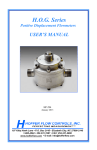
a computer is pictured in Figure 2.16. A frame consists of four parts: Ethernet
header, USRP transport header, Fixed payload header and payload; a Configure receiver command and a Generic request/reply command in this example.
The Ethernet header is 14 bytes and consists of a six-byte Destination address,
a six-byte Source address and a two-byte Type field. The latter indicates the
kind of data encapsulated in the Ethernet frame. The flow of packets is controlled. The USRP transport header contains a one-byte sequence number field
(seqno), numbering the current frame, and a one-byte acknowledgement field
(Ack), confirming to the peer reception of all frames up to the value stored in
Ack. In other words, the field Ack contains the number of the next expected
frame. The Fixed payload header contains a Channel number, three-bit flags
(used for computer to USRP frames only) and a Timestamp. The field Channel
is used for multiplexing different flows of frames on the same Ethernet link.
For example, there is a flow for computer to USRP control commands. There
are also data flows, i.e., the streams of samples. Each of them is identified by
a logical channel name. Immediate is the first of the three-bit flags. When
set, it indicates that the frame should be sent now. Start of burst is the
second flag and marks the beginning of a sequence of frames logically related
together. The end of the sequence of frames is marked with the flag End of
burst set. Timestamp contains either the time when the frame should be sent,
by the sender, or when it was received, by the receiver.
50
CHAPTER 2. SOFTWARE DEFINED RADIO ARCHITECTURE
Software Defined Radio
© 2015 Michel Barbeau
2.3.2
ft
The payload is a variation point. Figure 2.16 illustrates a frame where the
payload starts with a Configure receiver command. The first line starts with a
one-byte field indicating the exact type of command (opcode). In this example,
the opcode would be CONFIG RX. Next, there is a one-byte field indicating the
length, in bytes, of the command (Len). The one-byte RID field is a request
identifier, incremented from one command to another. On the second line,
the field Bitmask contains bits indicating which of the following fields apply.
For instance, if this command is issued to set the frequency, then the bitmask
has the configure frequency bit on. There is a two-byte field to store the radio gain (Gain). An eight-byte field is loaded with a desired radio frequency
(Frequency). A four-byte field specifies a decimation factor (Decimation). The
end of the payload is marked by a Generic request/reply command. In that case,
the operation code is end-of-operation. The field Len is interpreted as in a Configure receiver command. The fields left blank are not used.
Receiving Samples
D
ra
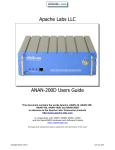
Figure 2.17 illustrates a scenario in which an application, running on a computer,
communicates with a USRP unit to trigger the transmission of an incoming flow
of samples. These are typically the communications involved when the execution
of a receiver application is launched. Both the computer and USRP unit have
an Ethernet interface and are connected by an Ethernet cable. Each of them
has a unique six-byte MAC address. A standard broadcast MAC address is also
involved in the scenario.
The application searches the Ethernet for all USRP units. (1) On the control
channel, a command is sent with the opcode ID. The command is encapsulated
in a frame sent using the broadcast MAC destination address. (2) Every present
USRP unit may reply with a frame encapsulating a command with the opcode
ID REPLY. For 50 milliseconds, the application waits, grabs all the replies and
builds a list of discovered USRP units, using their MAC address. By MAC
address, the application may also select a particular unit among all the replies.
On the control channel, the computer successively sends the commands to set
the (3) receiver gain, (4) center frequency, (5) decimation rate and (6) trigger
the transmission of the flow of samples. (7) Samples arrive in frames. The
payload part of each frame contains a number of samples. Frames are handled
individually in the sequence of arrival.
2.4
Signal Processing Block Detailed Design
In this section, we explain how a GNU Radio signal processing block works. Two
programming languages are involved. Regarding importation of blocks from
the GNU Radio API, the importer (i.e., the program using them) is written
in Python, as shown in Section 2.2. The blocks are, however, implemented
in C++. The reason being that Python is a script programming language
relatively easier to use than C++. The latter, however, does achieve much
CHAPTER 2. SOFTWARE DEFINED RADIO ARCHITECTURE
51
© 2015 Michel Barbeau
Software Defined Radio
ra
ft
better performance. This is important in digital signal processing involving a
lot of repetitive calculations.
The GNU Radio class gr.flow graph block is the base abstraction of signal
processing blocks. It has ports that may be of type float or complex. Every
specific block is defined as a specialization class derived, directly or indirectly,
from the base class gr.flow graph block. A specific block is coded as three
related pieces of code. The first piece is stored in a C++ header file (with
extension .h) and declares the interface of the block, e.g., the methods and their
signature. The second piece is stored in a C++ program file (with extension
.cc) and defines the implementation of the block, e.g., the algorithms of the
methods. The program is compiled into a dynamic library. The third piece
specifies which methods from the C++ declaration of the block should be visible
to the Python importer, i.e., it is a view on the block in Python. A tool,
dubbed Simplified Wrapper and Interface Generator (SWIG), produces the code
in Python interfacing with the C++ code in the dynamic library.
Let’s now have a closer look at an outline of the definition of a block in C++.
The use of arrays to buffer samples is an important aspect of the implementation
in C++. Conceptually, the flows of samples entering and leaving a block are non
interrupted streams. In reality, samples enter and leave in arrays. Every signal
processing block declares and defines the method general work. The runtime
environment repeatedly calls this method. Every call is parameterized with an
array of input samples and outputs an array of samples. Here is an outline of
the code of a block.
#include <vector>
#include <stddef.h>
typedef std::vector<int> gr vector int;
typedef std::vector<void *> gr vector void star;
typedef std::vector<const void *> gr vector const void star;
D
class gr block {
public:
virtual int general work (int noutput items,
gr vector int &ninput items,
gr vector const void star &input items,
gr vector void star &output items) = 0;
};
class my block : public gr block
{
public:
int general work (...same as above...)
{
// ...signal processing...
return noutput items;
}
};
The parameter noutput items designates the number of samples that are produced in each output stream, upon completion of the execution of the method.
52
CHAPTER 2. SOFTWARE DEFINED RADIO ARCHITECTURE
Software Defined Radio
© 2015 Michel Barbeau
The parameter ninput items specifies the number of samples present in each
input stream. The pointer input items refers to the arrays of input samples,
one array for each input stream. The pointer output items refers to the arrays
of output samples, one array for each output stream. Upon completion of its
execution, the method general work returns the number of samples actually
produced in each output stream.
Further Reading
ft
2.5
D
ra
Mitola’s book Software Radio Architecture - Object-Oriented Approaches to
Wireless Systems Engineering was the first to address the SDR architecture
topic [50]. Detailed information about the architecture of the USRP family of
SDRs is available at the web site www.ettus.com. Chapter 8 of the Radio Communication Handbook from the Radio Society of Great Britain [13] contains a
detailed review of the hardware architecture of the HPSDR. Also, check the web
site openhpsdr.org. Documentation about the GNU Radio framework, including
examples and source code, can be obtained at gnuradio.org. GNU Radio Python
examples have been published in Chapter 18 of the book Cognitive Radio Communications and Networks edited by Wyglinski et al. [83]. Computer network
concepts are required to reach a full understanding of the protocol architecture
issues related to the communications between a computer and a SDR using a
network interface such as Ethernet. On computer networks, we refer the reader
to the books of Peterson and Davie [57], Stallings [69] and Tanenbaum and
Wetherall [74]. Youngblood’s series of articles A Software Defined Radio for the
Masses are pioneering works on SDR for experimenters. They cover SDR to
computer analog communications and sound card programming [86, 87, 88, 89].
Critcal reviews of the FlexRadio SDR-1000 have been authored by Ford [17] and
Lindquist [39]. Silver wrote a critical review of the FlexRadio Systems SDR1500 [65]. Lindquist wrote a review for the FlexRadio Systems FLEX-5000A,
SDR part is the same at he FLEX-5000c [40]. These reviews reflect pretty well
the benefits and challenges associated with the utilization of SDRs.
The GNU Radio classes are documented in the Simple User Manual for
GNU Radio 3.1.1 [19]. Unfortunately, this useful manual is not up-to-date
with respect to the latest versions of GNU Radio. The automatically generated
documentation GNU Radio X.Y.Z C++ API [19], where X.Y.Z is the number of
the release of GNU Radio, is up-to-date but mainly covers the material from the
C++ perspective. There are rules facilitating the mapping of C++ elements to
Python. Given a GNU Radio C++ class with a named such as gr.class, there
is a friend constructor function of the form gr make class that is mapped by
SWIG to a Python function of the form gr.class(). Methods defined in C++
are mapped to Python under the same names and analogous signatures. The
similarity of C++ and Python helps a lot in understanding the automatically
generated documentation. In the Python environment, help can be obtained
about what is available in a module, e.g., audio, by first importing it, i.e.,
with the statement from gnuradio import audio, and entering the following
CHAPTER 2. SOFTWARE DEFINED RADIO ARCHITECTURE
53
© 2015 Michel Barbeau
Software Defined Radio
D
ra
ft
command help(audio).
54
CHAPTER 2. SOFTWARE DEFINED RADIO ARCHITECTURE
© 2015 Michel Barbeau
ra
ft
Software Defined Radio
D
Figure 2.16: A computer to USRP frame.
Figure 2.17: Receiving samples from a USRP unit.
CHAPTER 2. SOFTWARE DEFINED RADIO ARCHITECTURE
55