1
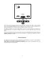
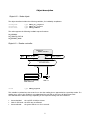
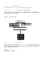
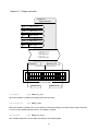
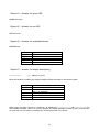
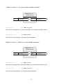
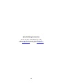
BUILDING AUTOMATION JLon Identification Terminal User’s Manual Application Program JLONM03 – June 2001 Important Notice The information included in this document is property of Apice s.r.l and can be changed without notice. Apice s.r.l. will not be liable for errors that might be contained herein and for direct or indirect accidental damage related to the supply, performance or use of the material which this document refers to. It is forbidden to make soft and hard copies of this document, to translate or manipulate all or part of it without the prior written consent of Apice s.r.l. Publications First edition – October 2000 Second edition – March 2001 Third edition – June 2001 Introduction The JLON is a LONWORKS based terminal designed to provide an identification point in the Globe2000 Access Control System. It consists of a 12-key keyboard and a 32- character LCD display, and can be equipped with an embedded magnetic or proximity card reader. It is normally used any time a high security identification point is required, where the access is granted only if a double recognition card plus PIN Code is successfully managed. For security reasons, the JLON does not report the contacts used to physically unlock the gate, since it is normally installed on the unprotected side of the building. For this reason it must be used in conjunction with the Apice IOL222 node to provide a complete gate control system. In this case the IOL222 will take care of driving the gate’s electric lock and will be installed on the protected side of the building. The outdoor reader can be either external or embedded in the JLON enclosure. In the first case the reader will be connected to the IOL222 inputs and the JLON will be used only for User PIN code acquisition and messaging. Whenever an authorized transit occurs on the gate the JLON will display a message managed by the Apice LonServer, the distributed field database manager. The JLON does not include on-board memory to store the user’s data and historical transit information. It simply captures the identification data and makes them available on the network, then the Apice LonServers will take care of checking in the field database and deciding whether to authorize the transit or not. 2 Technical Specifications Power supply Power consumption Keyboard Display Buzzer LEDs Test Head Inputs Transceiver Processor Clock frequency Service Interface Operating Temp. Relative Humidity Enclosure type Enclosure mounting Mechanical Dimensions Application Program Program ID XIF & NXE files NV count 12 VDC or AC, +/- 20%; 24 VDC or AC, +/- 20% 60 mA @ 12 V, 140 mA maximum with display backlighting activated 12 keys membrane 32 characters (2x16) alphanumeric LCD with backlighting Mounted on board 1 red LED and 1 green LED magnetic or proximity test head – TTL level - magstripe format LONWORKS FTT-10 78 Kb/s Neuron Chip 3150 10 MHz Service pin or manual entry – service led on board 0 – 50° C 20 – 80% non-condensing Plastic blend autoextinguishing Wall mounted or panel mount 150 x 90 x 45 mm JLONM03 90:0A:0E:00:01:00:40:03 jlonm02.xif jlonm02.nxe 16 Installation guidelines The JLON node can be placed both outside or inside the protected environment. It does not have the electric lock contacts on board, therefore a sabotage attempt aimed to unlock the door bypassing the unit will have no effect. The JLON needs only to be wired on the power supply and provided with a LONWORKS® network connection. The embedded reader, if present, is connected on factory. The user does not have to be concerned about making the right connection. The picture below shows the rear view of the JLON board, where the power supply and the network cables are to be connected. Regarding the power supply connection, please design the power supply line in a way to assure that the node is always powered within the specified operating range. 3 LED PIN SERVICE Reader connector 12V – 24V GND LON CK CP +5V DT The 60 mA current consumption reported on the spec table is a typical value valid in normal operation mode, when the display backlighting is kept off. Whenever a key is pressed, or a card is recognized by the reader, the backlight turns on and the current consumption rises up to nearly 140 mA. The node is insensitive to the power supply polarity, so there is no risk of damage if the supply line is swapped. Neverthless, no guarantee of integrity is provided if the power supply value rings out the spec range. As far as the LONWORKS® network connections are concerned, the JLON node must be wired following the guidelines reported into “Junction Box and Wiring Guidelines for twisted pair LONWORKS® networks” Engineering Bullettin, June 1999. Service Interface The JLON node mounts both the service LED and the service PIN button on board, for easy installation. These circuitry is not accesible by the outside of the enclosure. Please, make sure the node is installed and commissioned properly before re-mounting the cover and leaving the hardware in its final position. 4 Object description Object #0 – Node object The object interface includes the following variables, for LonMark® compliance: nviRequest nvoStatus nvoFileDir type SNVT_obj_request type SNVT_obj_status type SNVT_address The node supports the following LonMark request functions: RQ_NORMAL RQ_UPDATE_STATUS RQ_REPORT_MASK Object #1 – Reader controller Object #1 Reader controller nv nvidisable SNVT_lev_disc nv nvoId SNVT_magcard nciReaderMaxSndT SCPTmaxSendTime Magnetic or proximity card reader #1 nvoId LED #1 type SNVT_magcard This variable is updated any time a card is run into the reading slot or approached to a proximity reader. If a reading error occurs, the variable is not updated and the red LED on the cover will blink three times. The LEDs behave in different ways, depending on the response coming from the LonServer: • • • Access denided: the red LED #1 blinks 4 times. Wait for PIN code: the LEDs are not affected. Access allowed: the green LED turn-on for 1 seconds. 5 nvidisable type SNVT_lev_disc The input network variable nvidisable, if set to ST_ON value, disable the reader. nciReaderMaxSndT type SNVT_time_sec (SCPTmaxSendTime) This variable defines the maximum time the nvoId variable is refreshed, for hearthbeat purposes. Whenever a card is read by the reader, the new value is propagated once over the network, while the subsequent updates will have a zero value. Object #2 – Keyboard controller Object #2 Keyboard controller nv nvikeybDisable SNVT_lev_disc nv nviresetKby SNVT_lev_disc nv nvokeyboard SNVT_str_asc nciKeybMaxSndT SCPTmaxSendTime 1 2 3 4 5 6 7 8 YE S 9 0 NO JLON keyboard nvokeyboard type SNVT_str_asc Each time a key is pressed on the keyboard, the nvokeyboard network variable is updated. The last key pressed is loaded at the end of the string nvokeyboard.ascii until the buffer is full (maximum 30 characters allowed). In this condition, when a new key is entered all the string shift left one position and the new value is loaded at the right end position. Example 1: The user presses 4, 2, 5, 8 keys, nvokeyboard.ascii = 4258 6 Example 2: nvokeyboard.ascii = 4258..456 User press key 1 nvokeyboard.ascii = 258..4561 The oldest key is unloaded (the buffer is full) (the buffer is full) The last key entered is loaded at the end nviKeybDisable type SNVT_lev_disc When this variable is set to ST_ON, the nvokeyboard.ascii string is cleared and the keyboard is disabled. When the value is restored to ST_OFF, the keyboard is enabled for the normal operation. nviresetKby type SNVT_lev_disc When this variable receives an ST_ON update, the nvokeyboard.ascii string is cleared. nciKeybMaxSndT type SNVT_time_sec (SCPTmaxSendTime) This variable defines the maximum time the nvokeyboard variable is refreshed, for hearthbeat purposes. Whenever a PIN code is inserted, the new value is propagated over the network, while the subsequent updates will repeat the same value. 7 Object #3 – Display controller Object #3 Display controller nv nvidisplay SNVT_str_asc nv nvicurPosition SNVT_count nv nvicurShape SNVT_lev_disc nv nviPresCount SNVT_count nv nvirefreshEnable SNVT_switch nciDispRefresh UCPT_dly_refresh nciDispRaw1 UCPT_disp_raw1 nciDispRaw2 UCPT_disp_raw2 Position #1 Position #16 16x2 LCD display Position #32 Position #17 nvidisplay type SNVT_str_asc When this variable is updated, the display will show the string. nvicurPosition type SNVT_count When this variable is updated, the cursor position is varied accordingly: the valid numeric range is between 1 and 32. If the variable assumes value 0, the display is cleared. nvicurShape type SNVT_lev_disc This variable changes the cursor shape according to the following table: 8 value ST_OFF ST_LOW ST_MED ST_HIGH ST_ON nviPresCount Cursor shape No cursor Blink Normal Not allowed Not allowed type SNVT_count This variable is intended to be bound to the LonServer’s nvocount variable, for special applications in which you need to display on the JLON the number of people registered on a certain area. nviRefreshEnable type SNVT_switch This variable allows you to refresh periodically the display with a user defined message programmed with the UCPT parameters reported below, independently from the message forced by the LonServer in correspondance of any authorised or unauthorised transit. After the message coming from the LonServer is displayed, if the state field of the nviRefreshEnable variable is 1 the display will be refreshed with the user defined message, otherwise it will not. The display will also show on the bottom right corner the number of users registered in the area, as indicated by the nviPresCount variable. The display is automatically refreshed at intervals programmed in variable nciDispRefresh, but it is always possible to force the refresh immediately by programming the nviRefreshEnable value field at a value greater than zero. nciDispRefresh type SNVT_time_sec (UCPT_dly_refresh) This variable defines the time interval for automatic refresh of the display with the user defined message. nciDispRaw1 type SNVT_str_asc (UCPT_disp_raw1) This variable defines the user defined message that will appear on the upper row of the display. This message can be as long as 16 characters. The default value is: UTENTI. nciDispRaw2 type SNVT_str_asc (UCPT_disp_raw2) This variable defines the user defined message that will appear on the lower row of the display This message can be as long as 12 characters (because the last 4 digits are used to display the number of users indicated by variable nviPresCount). The default value is: REGISTRATI. The variables can be easily changed to display REGISTERED USERS, instead of UTENTI REGISTRATI, or whatever is needed. 9 Object #4 – Actuator for green LED GREEN LED driver. Object #5 – Actuator for red LED RED LED driver. Object #6 – Actuator for embedded buzzer BUZZER driver. value ST_OFF ST_LOW ST_MED ST_HIGH ST_ON Buzzer OFF Short beep Long beep Four short beep ON Object #7 – Actuator for display backlighting nvibackLigth type SNVT_lev_disc When this variable is updated, the display backlight changes according to the following table: value ST_OFF ST_LOW ST_MED ST_HIGH ST_ON BackLigth OFF ON and turn-off after nciMaxDTime (UCPT_dly_backlight) ON Not allowed Not allowed NOTE: when the JLON is bound to a LonServer, all variables but nvokeyboard and nvo01magcard are automatically managed. There is no need to program the display backlight to switch off after a certain time an event has occurred, neither to activate the red and green leds or the buzzer. 10 Object #8 and 9 - Logic Controllers Objects #8 - 9 Logic controller nv nviInput[0]-[1] SNVT_switch nv nvoOutput[0]-[1] SNVT_switch nciLogicMode[0]-[1] SCPTdirection nviInput[0]-[1] type SNVT_switch This is an array of two input network variables for the two Logic controllers. Multiple output variables can be bound to this input of the controller, because any operation will always be accomplished by polling this input. nviOutput[0]-[1] type SNVT_switch This is an array of two output network variables, representing the result of the operation made on the network variables bound at the inputs nviInput. The following types of operation are possible: AND, OR, NAND and NOR. nciLogicMode[0]-[1] type SNVT_state (SCPT direction) This is an array of two configuration network variables which allow to set the operating mode of the relevant controller. Only the least significant two bits are meaningful: BIT 0: 0 – makes an OR operation on the input variables (default) 1 – makes an AND operation on the input variables BIT 1: 0 – the result of the operation programmed by BIT 0 is not inverted (OR/AND operations) 1 – the result of the operation programmed by BIT 0 is inverted (NOR/NAND operations) 11 Object #10 and 11 – Lev_disc to Switch variable converters Objects #10 - 11 Variable converter nv nvilev[0]-[1] nvilev[0]-[1] SNVT_lev_disc nv nvoswitch[0]-[1] SNVT_switch type SNVT_lev_disc These are the incoming SNVT_lev_disc type variables, to be converted into SNVT_switch. nvoswitch[0]-[1] type SNVT_switch These are the outcoming SNVT_switch type converted variables. Object #12 and 13 – Switch to Lev_disc variable converters Objects #10 - 11 Variable converter nv nviswitch[0]-[1] nviswitch[0]-[1] SNVT_switch nv nvolev[0]-[1] SNVT_lev_disc type SNVT_switch These are the incoming SNVT_switch type variables, to be converted into SNVT_lev_disc. nvolev[0]-[1] type SNVT_lev_disc These are the outcoming SNVT_lev_disc type converted variables. 12 Apice Building Automation Via G.B. Vico 45b – 50053 Empoli (FI) - Italy Phone +39 0571 920442 Fax +39 0571 920474 email: [email protected] Home page: www.apice.org 13