1
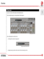
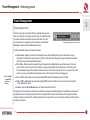
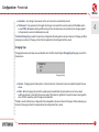
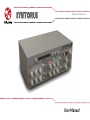
Double Path Analog Chorus User Manual Overview Overview 1 Syntorus is a chorus effect emulator with double delay line. After loading the plug-in to a host application the GUI appears: Syntorus graphical interface We can distinguish two sections there: • Configuration and preset management: Configuration and preset selection section • Signal processing control section consists of the all remaining controls. 1 Signal flow • Basic modules Signal flow This chapter describes the path of the signal’s flow through the Syntorus plug-in, presents the basic components of this effect unit and its control parameters. 2 Basic modules The inside of Syntorus consist of a few basic components, that correspond to the sections on the graphical interface: Path 1 It’s a first of two delaying lines in Syntorus controlled by its own LFO, which can be synchronized to the host application. Apart from that each Path can work as Tremolo as well. First path Following parameters control a first path: • W aveform – Chooses a shape of LFO’s waveform among: triangle, square, sine, sawtooth (ascending or descending), noise. 2 Signal flow • Basic modules • Offset – It’s a offset between dry signal and the minimum of the LFO’s oscillations expressed in milliseconds. • Depth – Amplitude of LFO’s oscillations expressed in milliseconds. • Rate – Controls LFO’s frequency. 2 To see how the LFO controls a delay line take a look at the figure below: Single delay line If you imagine a Path (delay line) as a reading head moving through signal, in that case LFO controls its acceleration. • Path volume – Path’s output volume. • Tremolo – Adds a tremolo effect to the Path’s output, frequency of tremolo is also controlled by a Rate knob. 3 Signal flow • Basic modules • S t.Phase – In a case of stereo signals, left and right channel are processed independently. That means, left and right channel has its own LFO. When St.Phase is set to 0 degree, LFO for right and LFO for left channel have the same phase. Increasing Phase value, increases the phase shift between LFOs, making a pleasant stereo effect. 2 LFO stereo phase shift When Syntorus is inserted in a mono track, St.Phase knob doesn’t work. • T emp sync. – It’s possible to sync Path’s LFO with host application. This switch is used for this purpose. There’re four available values: – Off – Synchronization is off, the LFO’s frequency is controlled via Rate fader arbitrarily in a range 0 to 20 Hz. –Full – Synchronization is on, the LFO’s period length is equal to a single note set on Rate fader, respectively to host’s tempo value. 4 Signal flow • Basic modules –Dotted – Synchronization is on, the LFO’s period length is equal to a single dotted note set on Rate fader, respectively to host’s tempo value. –Triplet – Synchronization is on, the LFO’s period length is equal to a single triplet note set on Rate fader, respectively to host’s tempo value. 2 • W hen synchronization is on, LFO’s rate can be set to following values: 1, 2, 4, 8 and 16 bars, half note (½), quarter note (¼), eighth (1/8), sixteenth (1/16) and thirdy-second (1/32). One bar Dotted note is a 3/2 longer than Full note, Triplet note is 2/3 of Full note. Note lengths 5 Signal flow • Basic modules Path 2 Basically Path 2 doesn’t differ to a Path 1. Using two Paths at once makes sound even fatter. The only difference is a Sync with LFO 1 switch. When this switch is set to Off position, the two Paths process signal totally independently. But when we set that switch to On position, the second path (Path 2), becomes a slave. All of its controls work in regular way, apart from a Rate fader, which value is taken from Rate fader of Path 1 – that includes also synchronization. 2 Second path Sync with LFO1 switch 6 Signal flow • Master section Master section 2 Controls the end of signal’s flow. Master section • D ry / Wet – Controls proportions between unprocessed and processed signal sent to output. • O utput volume – Controls the final amplification. • B BD – It’s a switch that turns on Bucket-Brigade Device emulation, which is discrete-time analogue delay line. It causes bigger usage of CPU, but affect on more pleasant and warm character of chorus. • H i pass – There’s a hi-pass, that filters whole wet signal outgoing from delay lines. This parameter controls filter’s cut off frequency in a range of [ 0 Hz … 800 Hz ]. 7 Signal flow • Path of the signal’s flow Path of the signal’s flow 2 The picture below shows how the signal flows through the plug-in: Signal flow 8 Preset Management • Browsing presets Preset Management 3 Browsing presets Presets in the plug-in are hierarchically organized in groups and, contrary to the linear structure, this setting is not compatible with the native methods used within the host application. The user can see the presets assigned to particular groups in the Preset Manager. Groups can be also defined by the user. Configuration and preset selection section Controls available in the preset selection section: • P reset name – Displays the name of the selected preset. Allows editing of the preset name before saving the preset. Clicking on the control causes a shift into edit mode. After applying changes through the keyboard, confirm the new name with the Enter button. • P rev / Next – Buttons used to navigate through the preset bank. Next button moves the browser to the next preset. If the current preset is the last preset in a group, pressing Next moves the browser to the first preset in the subsequent group. Prev button moves the browser to the previous preset. If the current preset is the first preset in a group, pressing Prev moves the browser to the last preset in the preceding group. Note: On MacOS use Apple CMD key instead of CTRL key. • P rev + CTRL – Prev button pressed while holding CTRL copies the edited preset to the buffer. • N ext + CTRL – Next button pressed while holding CTRL pastes the buffer to the current preset with postfix “_copy” added to its name. • B rowse – Opens a Preset Browser menu in the bottom part of the GUI. Changes in the preset bank are not permanent. After removing and reloading the plug-in, the default preset bank will be loaded. However, saving the project within the host application will also save the status of the plug-in including changes in the preset bank. After reloading the project, all changes in the current parameter settings and in the preset bank will be restored. 9 Preset Management • Preset Browser Preset Browser As it was mentioned, the preset bank in the plug-in has a hierarchical structure i.e. presets are organized in groups. Presets can be selected by Next/Prev buttons, which navigate through the structure in a linear way or by using the Preset Browser. The Preset Browser is a tool which allows to easily manage the preset structure. To open it, click Browse in the preset selection section: 3 Configuration and preset selection section The Preset Browser will unfold under the GUI: Preset Manager 10 Preset Management • Preset Browser The left side shows the list of groups in the preset bank: The right side shows the list of presets in the selected group: List of groups in the preset bank List of presets in the selected group 3 11 Preset Management • Preset Browser Actions available in the Preset Browser: • Clicking on a slot in the preset list loads the selected preset. • Clicking on a slot in the group list selects a group of presets. 3 • B oth presets and groups can be renamed. Double clicking on a slot toggles edit mode. After entering the new name, press enter to finish. • T he bank of presets has exactly 128 items. The number of presets cannot be changed. This means that there is no possibility of adding or removing presets. Only relocating them between groups or changing their order is possible. By dragging the preset you may: Note: Changing the order of presets in a group is possible for a selected single preset. Changing the order by dragging several presets in a group is inactive. – Change its position in the group by dropping it in a different slot in the list of presets in a selected group. – Move the preset to a different group by dragging and dropping it in the chosen slot in the group list. Holding CTRL or SHIFT and using the mouse button allows to select more presets: – Holding CTRL and clicking on presets selects single items. – Using SHIFT allows to select a range of presets. The first click marks the beginning of the range and the second click marks the end. When more than one presets are selected, it is possible to drag them to a different group. 12 Preset Management • Preset Browser On the left side of the Preset Browser there are function buttons located: – Adds a new empty group to the preset bank. 3 – Removes a group from the preset bank, but only if the selected group is empty. Before removing a group, remaining presets should be relocated to different groups. An empty group can be recognized by the lack of bold font and the lack of a pointer on the right from its name. Empty group in the Preset Browser – Pastes the edited preset to the buffer; works exactly like the combination of Prev and CTRL. – Overwrites the selected preset with the buffer content; works exactly like the combination of Next and CTRL. The postfix “_copy” is added to the name of the preset pasted from the buffer. Function buttons of the Preset Browser – Works exactly like Prev on GUI; allows to move backwards on the hierarchical structure of presets. – Works exactly like Next on GUI; allows to move forward on the hierarchical structure of presets. 13 Preset Management • Preset Browser Loading and Saving presets At the bottom of the Preset Browser there are function buttons which allow to save/load presets on/from the hard drive. 3 Loading and Saving presets from the hard drive functions Four buttons are available: • Preset Load – loads a single preset from a file (file .snprs – Syntorus preset). Note: Before saving the preset to a file, save it in Syntorus using CTRL + Browse when On demand function is selected in the plug-in configuration. • Preset Save – saves the current preset to a file. • Bank Load – loads the entire bank of presets from a file (file .snprb – Syntorus bank). • Bank Save – saves the entire bank of presets to a file. Note: Files saved by Syntorus are compatible with XML format, which enables their edition in any text editor. 14 Configuration Configuration 4 Configuration and preset selection section After clicking on Options in the preset selection and configuration section, a configuration panel unfolds in the bottom section of GUI. The panel has two tabs: Configuration panel tabs • M idi control – configures MIDI communications with the plug-in. • P resets – configures presets switching; indicates personal resources loaded instead of default presets. Clicking on Options while holding CTRL opens a window with information about the version and the license owner. 15 Configuration • Midi control tab Midi control tab Note: This feature works only in the VST version of the plug-in, due to the fact that the AU specification does not include a MIDI input port necessary to receive MIDI messages. Syntorus can assign its controls (on GUI) to any MIDI CC (Midi Control Change), allowing the control of the plug-in using external hardware or software. 4 Midi Control tab Controls included in the tab: • M idi learn mode – Checkbox which activates Midi learn mode. • A list of active MIDI CC links containing pairs comprising of a CC code and the name of the plug-in parameter. • D efault Map – Checkbox which activates a default MIDI CC map. When the map is activated it will be loaded with creating a new instance of the plug-in. 16 Configuration • Midi control tab Midi learn 4 Assigning a Syntorus control to the MIDI controller requires: 1. Checking Midi Learn Mode checkbox in the Midi Control tab: Midi Learn Mode selection checkbox 2.In the status bar in the bottom section of GUI a message should appear “waiting for a controller or parameter movement…”: Status bar I n this mode the plug-in waits for any change in the parameter value (movement of any control on GUI) and for the movement of any MIDI CC control from the external MIDI controller, which operates on an active MIDI input channel directed to Syntorus. The order of these actions is irrelevant. D uring the above-mentioned actions, the status bar informs about the currently changing values of controls and provides their names. 17 Configuration • Midi control tab When a MIDI control <–> GUI control link is established, a line is added to the MIDI CC link list: 4 MIDI CC link list W hen a link is established for a controller, it is possible to repeat the operation for the next MIDI CC and parameter pairs. Subsequent links will be created and added to the list. 3. When all the needed links are created, uncheck the Midi Learn Mode checkbox. In order to create new links, it is possible to reactivate the Midi Learn Mode at any time. The links are always sorted in an ascending manner in relation to the CC column according to the MIDI CC code. 18 Configuration • Midi control tab Unlinking and midi link management 4 On the right side of the link list there are 4 function buttons located: MIDI CC link list and function buttons – Removes a selected link; choosing any link from the list and clicking on it highlights the selected link. Using this button removes the selected link. – Removes all MIDI CC links. – Loads link lists/MIDI maps from file (.snccmap – Syntorus MIDI CC Map). Note: MIDI map files are saved in XML format, which enables their edition in any text editor. – Saves link lists/MIDI maps to file. 19 Configuration • Midi control tab • Presets tab Default MIDI Map 4 Selecting a default MIDI Map: Default MIDI Map selection 1. Check the Default Map checkbox, which activates the Browse button on the right. 2. Click Browse and select a file with a saved MIDI Map. After selecting the MIDI map the text box on the left from the Browse button shows the path to the active map file. A default MIDI map is loaded each time when the plug-in is loaded. Presets tab Preset Storing Using Prev, Next buttons or the Preset Browser navigates through the preset bank. Any change in the current preset can be stored automatically or on demand. Depending on the selection one of the two options is active: Preset Storing flag 20 Configuration • Presets tab • Automatic – Any change of a parameter in the current preset is automatically stored. • O n Demand – If any parameter is changed, the change is not saved in the current preset until the Store option is used (CTRL + Browse). Selecting a different preset from the bank causes irreversible loss to changes applied to the parameters, unless the Store option is used. 4 The Preset Storing flag is saved in the Syntorus configuration file and applies to all new instances of the plug-in. When removing any instance of the plug-in from the host application the configuration file is saved. Changing Type Changing between presets may cause undesirable sonic artifacts. Switching the Changing Type flag may prevent this phenomenon. Changing Type flag • N ormal – Changing presets takes place in a classical manner; all parameter values are rapidly changed into new values. • S ilent – Before changing the preset the output signal is muted. Next, the parameters are set to new values and the signal level is restored to its previous value. This feature is significant in live performances, during which, sonic artifacts caused by preset changes are undesirable. The flag is saved in the Syntorus configuration file and applied to all new instances of the plug-in. When removing any instance of the plug-in from the host application the configuration file is saved. 21 Configuration • Presets tab Default Presets D16 provides a set of default presets with Syntorus. They are applied to every new instance of the plug-in. If a bank of presets is created which should be applied every time instead of factory presets, it is possible to select such an on option Default Presets section: 4 Default presets selection Options available in the Default Presets section: • F actory Presets – Default value after installing Syntorus. Choosing this option loads the factory presets with every new instance of the plug-in. • C lear Preset – Zeroed parameters with every new instance of the plug-in. • U ser Defined – Preset bank selected by the user. When choosing User Defined option, the Browse button on the right side is activated. Using this button opens a dialog box in order to select a path to the user’s preset bank. Confirming the path saves it in the Syntorus configuration file. The selected preset bank will be loaded as default. The text box on the left from the Browse button shows the path to the user’s preset bank. 22 Contents Contents 1 Overview . ............................................................................. 1 Presets tab ........................................................................ 20 2 Signal flow ............................................................................ 2 Preset Storing ............................................................. 20 Basic modules .................................................................. 2 Changing Type . ........................................................... 21 Path 1 . ............................................................................ 2 Default Presets . ......................................................... 22 Path 2 . ............................................................................ 6 Master section . ............................................................... 6 5 5 Contents ................................................................................ 23 Path of the signal’s flow ............................................... 8 3 Preset Management ......................................................... 9 Browsing presets . .......................................................... 9 Preset Browser ............................................................... 10 Loading and Saving presets ................................... 14 4 Configuration ...................................................................... 15 Midi control tab .............................................................. 16 Midi learn ...................................................................... 17 Unlinking and midi link management ................ 19 Default MIDI Map ..................................................... 20 23