1
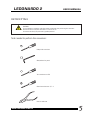
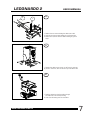
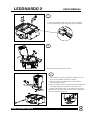
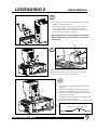
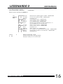
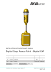
LEDONARDO
2
USER MANUAL
BROTHER, BROTHER & SONS ApS
LEDONARDO 2
USER MANUAL
INTRO
Brother, Brother & Sons ApS
The information in this manual is subject to change without notice.
Go to www.brothers-sons.dk for the latest version.
Brother, Brother & Sons ApS assumes no responsibility for any errors or inaccuracies that may
appear in this manual. All information and graphics are the property of Brother, Brother & Sons
ApS.
User Manual Version: December 2011
Customer and Warranty service:
Contact your regional dealer. Contact information for your area can be found at www.brotherssons.dk
RMA:
When returning an item please enclose
a.: Model and Serial number.
b.: A description of the problem
c.: The name of the owner of the equipment.
d.: If available please include a copy of your invoice to establish the date of sale and the beginning
of the warranty period.
Disposing of this product:
Help preserve the environment! Ensure that this product is recycled at the end of its life.
This product is in compliance with the RoHS and WEEE directives.
In compliance with EMC standards:
EN 55103-1 & EN 55103-2:
EN 55022, EN 55103-1 Annex A, EN 55022, EN 61000-3-2, EN 61000-3-3, EN 55103-1
EN 61000-4-2, EN 61000-4-3, EN 61000-4-4, EN 61000-4-5, EN 61000-4-6, EN 55103-1
Annex B, EN 55103-1 Annex A, EN 61000-4-11
Brother, Brother & Sons ApS - The information in this manual is subject to change without notice.
Go to www.brothers-sons.dk for the latest version.
WWW.BROTHERS-SONS.DK
1
LEDONARDO 2
USER MANUAL
CONTENTS
Intro..........................................................................................................................
Index..........................................................................................................................
Safety Information......................................................................................................
Maintenance..............................................................................................................
Product Overview........................................................................................................
Conversion.................................................................................................................
First Time Usage / Installation......................................................................................
AC Power....................................................................................................................
DMX Data Link............................................................................................................
Software Update........................................................................................................
DMX Protocol.............................................................................................................
Software Menu...........................................................................................................
Specifications.............................................................................................................
WWW.BROTHERS-SONS.DK
1
2
3
3
4
5
12
13
13
13
14
15
17
2
LEDONARDO 2
USER MANUAL
SAFETY
Safety Notice:
It is important to read ALL safety information and instructions in this manual before installing and operating the product described.
Safety symbol used in this manual:
WARNING: Potential injury or damage to persons or product.
WARNING:
It is important to read ALL safety and installation instructions to avoid any damage to the
product and potential injury to yourself and others.
This product is for professional use only and has been designed for indoor use. Exposure to
moisture may cause damage to the product and will void your warranty.
This fixture is designed for use with a specific LED only. Use of any other type LED may be
hazardous and may void warranty.
Do not operate the product if the ambient temperature exceeds 35°C / 95°F
Provide a minimum clearance of 0,1m (4 in.) around fans and air vents.
Do not mount on flammable surface.
Ensure that the fixture is electrically connected to ground (earth)
Only use this product if all cables, connectors and the product itself are undamaged.
Damage caused by inadequate cleaning or maintenance is not covered by the product warranty.
This is a product using High power LEDs. Do not stare directly into the LED at extended
periods of time at a short distance without suitable protective eyewear. Do not look directly
at the LED with optical instruments that concentrate the light output.
No matter the light source, blue light, depending on the wavelength, can be harmful to your
eyes.
SERVICE:
Servicing is to be performed only by qualified personnel. Take precautions to avoid ESD
damage during service.
Disconnect the power before servicing the product.
MAINTENANCE:
This product requires very little routine maintenance, if any, but has special cleaning
instructions:
Disconnect fixture from power and allow it to cool for 10 min.
Vacuum or gently blow away any dust from fan blades and grills
Very gently clean the LED with Isopropyl alcohol.
Clean the lenses with a soft damp cloth.
Power:
Never connect to dimmer power
WWW.BROTHERS-SONS.DK
3
LEDONARDO 2
USER MANUAL
PRODUCT OVERVIEW
399,80 mm / 15,74”
527 mm / 20,75”
357,5 mm / 14,07”
415,75 mm / 16,37”
LEDonardo 2 - LED Light Engine
Cable access
corner
Controlbox
Tower
6 x washers
Safety Sticker
Air cover
6 x Philips PH2 Screws
2 x Cable Ties
WWW.BROTHERS-SONS.DK
Cable Strain Relief
4
LEDONARDO 2
USER MANUAL
RETROFITTING
CAUTION !!
To avoid damage to equipment take electrostatic precautions when performing the conversion
Disconnect fixture from power and allow it to cool for 10 min.
Conversion should only be performed by qualified personel.
Tools needed to perform the conversion:
Phillips PH2 screwdriver
Allen/Umbraco key size 4
Torx srewdriver size T10
Slotted srewdriver size 3,5 - 4
Pliers for cable ties
WWW.BROTHERS-SONS.DK
5
LEDONARDO 2
USER MANUAL
1
Unscrew the four screws as illustrated and remove the lamp
section.
2
NOTE:
The guide bar is not symmetrical, so it is recommended to mark
one end, to make sure that you remount it correctly.
Not doing so will affect the optical system.
As a rule the distance between the locking rings is smaller at
the front (A) and larger in the back (B).
B
A
Using a screwdriver, remove the four locking rings on the guide
bar.
Slide the guide bar out and lift up the lampsocket / reflector
part. Be carefull not to loose the locking rings as you will
need them later.
3
With the lamp socket lifted, loosen the two Umbaco screws
and remove the cable from the socket.
Loosen the ground wire by removing the screw.
The socket is no longer needed and we are ready to start
mounting the LED Light Engine.
WWW.BROTHERS-SONS.DK
6
LEDONARDO 2
2
1
USER MANUAL
4
1. Remove the two screws holding the cable strain relief.
2. Unscrew the three screws holding the on/off switch box.
3. Remove the on/off box and the cables including all ground
wires.
5
1. Remove the cable access corner on the Tower by unscrewing the Torx 10 screw, save the screw as you will need it later.
6
1. Feed the cables from the Controlbox through
the cable hole in the old lamp housing.
2. Lower the old housing onto the controlbox
WWW.BROTHERS-SONS.DK
7
LEDONARDO 2
USER MANUAL
7
1. Mount the supplied cable strain relief with the supplied
screws and washers, and guide the cable through as illustrated.
8
1. Feed the cable through the Tower as shown.
9
A
WWW.BROTHERS-SONS.DK
1. Place the Tower in the old housing by first hooking it on to the
the unmounted guidebar using the two nothes A.
2. Lower the notch on the opposite side into the wirepulley
(see the illustration below)
3. Insert the guidebar that we previously dismounted and apply the
four locking rings again. Remember the orientation of the
guidebar ,(short distance at front, large distance in the back).
NOTE: The cable has been partly removed from the illustration to
prevent it from obscuring the view.
8
LEDONARDO 2
USER MANUAL
10
B
A
1. In this step we need to guide the cables from the Controlbox
through the Cable access corner.
First attach grommit A, mounted, on the cable to the slot
shown in the illustration. Next take the open grommit B
from the cable access corner and guide both the cable from
the Controlbox and the Tower fan through.
NOTE: The LED cable has a piece of heatshrink (C) mounted
where the cable tube stops. This needs to be on the LED side
of the grommit.
C
11
1. Mount the cable access corner with the Torx 10 screw.
When mounting, angle the corner as shown, to fit the notch
on the corner into the cutout in the Controlbox.
12
A
1. Now gently pull the cable from the Tower fan out to
tighten it.
2. Connect the LED cable and the two fancable ends.
3. Using the two supplied cable ties and the cable tie
fastener (A), tie down the cables to prevent them from
getting in front of the LED.
If possible, leave a small amount of excess cable on the
LED side of the cable tie fastener.
This will make it easier, should you need to replace the LED.
Approx. 8 mm / 0,31” loose cable.
WWW.BROTHERS-SONS.DK
9
LEDONARDO 2
USER MANUAL
A
13
1. Move the Tower all the way to the back
2. Pull the sliding lid (A) towards the front.
Now its time to mount the Air cover.
Slide it in from the front, making sure that it rests on top of the edge (B) above the Guide bar.
B
WWW.BROTHERS-SONS.DK
10
LEDONARDO 2
USER MANUAL
14
1. Carefully turn everything you have assembled up
side down. Remember that the sections are not attached to
each other securely yet.
15
1.
Place all the parts on bottom of the housing.
Screw in the four supplied screws and washers.
Now everything is attached securely.
16
1. Cover this area of the tech label on the back of the Desisti
with the supplied BBS sticker, for approval purposes.
WWW.BROTHERS-SONS.DK
11
LEDONARDO 2
USER MANUAL
INSTALLATION
Do not operate the product if the ambient temperature exceeds 35° C
Provide a minimum clearance of 0,1m (4 in.) around fans and air vents.
This fixture must be connected to ground.
This fixture is for indoor use only.
Remove plastic protection from the LED before applying power !
Read the “Safety” and “Specifications” chapters first.
Applying power:
Never connect to dimmer power
Make sure the local power voltage is within the range specified.
If so; connect the power cable and turn the power on.
Standalone operation:
Using the navigation buttons and display readout ( refer to the “Software Menu” chapter )
navigate to Manual and set the desired intensity.
( additional operations see “Software Menu” chapter)
DMX operation:
Connect a DMX cable
Navigate to Adress mode (Addr) and set the desired adress, resolution, response, strobe,
curve settings and in Personality (PErS) set the desired Fan, No DMX and Display settings.
(refer to the “Software Menu” and “DMX Protocol” chapters)
Connect to DMX controller.
(refer to the “DMX Protocol” chapter)
Use it.
WWW.BROTHERS-SONS.DK
12
LEDONARDO 2
USER MANUAL
AC Power
This fixture must be connected to ground.
Electrical:
AC Power: 100 – 240 V nominal, 50/60 Hz
Powersupply: Electronic switchmode
Max power consumption: 182 w
DMX Data link
This product uses a 5-pin XLR for dmx input and output.
Use a shielded data cables.
Do not overload the daisy chain. Up to a maximum of 32 devices can be used on a single dmx
chain.
DMX Channels:
1 at 8bit: Dimmer
2 at 8bit: Dimmer w. strobe
2 at 16bit: Dimmer
3 at 16bit: Dimmer w. strobe
Protocol: USITT DMX512-A
SOFTWARE UPDATE
Software can be updated via DMX512 with UPLOADER from Brother, Brother & Sons ApS
and the latest software version can be found on www.brothers-sons.dk.
WWW.BROTHERS-SONS.DK
13
LEDONARDO 2
Linear curve on Indicator
Software vers. 1_3_00
USER MANUAL
Response fast indicator
Strobe on Indicator
888888
8 bit Indicator
MENU
ENTER
UP
DOWN
DMX present indicator
Open menu / Go back
Select / Confirm
Scrolling UP / Increase value
Scrolling DOWN / Decrease value
DMX Channels
Mode
Channel
Parameter
Value
Percent
Function
8 Bit
1
Dimmer
0 - 255
0 - 100
Coarse dimming
8 Bit
w. Strobe
1
2
Dimmer
Strobe
mode
3
Strobe
length
0 - 255
0-5
6 - 125
126 - 130
131 - 250
251 - 255
0
0 - 100
0
1 - 49
50
51 - 99
100
0 - 100
Coarse Dimming
Open
Slow to Fast Strobe
Open
Slow to Fast Random
Open
Short to Long Flash
16 Bit
1
2
Dimmer
Dimmer
0 - 255
0 - 255
0 - 100
0 - 100
Coarse dimming
Fine dimming
16 Bit
w. Strobe
1
2
3
Dimmer
Dimmer
Strobe
mode
3
Strobe
length
0 - 255
0 - 255
0-5
6 - 125
126 - 130
131 - 250
251 - 255
0
0 - 100
0 - 100
0
1 - 49
50
51 - 99
100
0 - 100
Coarse dimming
Fine dimming
Open
Slow to Fast Strobe
Open
Slow to Fast Random
Open
Short to Long Flash
Note: Beware, when using Strobe Lenght, that if the Strobe Lenght is egual to or longer than
the flash and interval between flashes, the unit will not strobe.
If maximum strobe length is used the fastest strobe possible will be 17 ( 7% )
WWW.BROTHERS-SONS.DK
14
LEDONARDO 2
USER MANUAL
Software vers. 1_3_00
SOFTWARE MENU
Default values indicated by bold font
Addr
Mode
Tools
1
DMX adress value 1 - 512
Resolution
8 bit resolution
16 bit resolution
Response
Slow (fade between values)
Fast (snap between values)
Strobe
OFF
On - (adds 2 strobe channels)
Curve
Square dimmer curve
Linear dimmer curve
Fan
HIGH - No fan speed limit
LOW - Fan speed limited (Silent)
noDMX
Action when loss of DMX signal:
HOLD - last received DMX value
OFF - Sets output to zero
MAN - Go to Manual DMX value
Display
OFF 2n - Display off after 2 minutes
ON - Display always on
Ver
Shows software version - READOUT ONLY
HW Ver
Shows hardware version - READOUT ONLY
Temp
LED temperature - READOUT ONLY
DMX In
3 first digits shows DMX adress - READOUT ONLY
3 last digits shows DMX value - READOUT ONLY
Reset
Confirm (Reset unit by pressing enter)
test Fan
Fan test
First 2 digits - set fan speed level 0 - 31
Last 3 digits - RPS (rounds per second) - READOUT ONLY
test display
Display test - all seven segments of each digit on - READOUT ONLY
....continues on next page
WWW.BROTHERS-SONS.DK
15
LEDONARDO 2
USER MANUAL
Software vers. 1_3_00
SOFTWARE MENU
....continued
Default values indicated by bold font
Log
Max Fan
Fan RPS
EEProm
LED U
PSU U
LED int
Log C°
on time
on LED
Demo
DMX HZ
DMX CH
DMX br
LED EE
Manual
0
WWW.BROTHERS-SONS.DK
Maximum fan speed logged. (in RPS) - READOUT ONLY
Current fan speed (in RPS) - READOUT ONLY
Developer info
LED voltage in Volts - READOUT ONLY
PSU voltage in Volts - READOUT ONLY
for troubleshooting - READOUT ONLY
Minimum and maximum logged temperature in °C
UP and DOWN scrolls min. and max.
PSU on time in hours - READOUT ONLY
LED on time in hours - READOUT ONLY
Developer info
DMX refresh rate - READOUT ONLY
No. of DMX ch. transmitted by controller. - READOUT ONLY
Break lenght of DMX in microseconds - READOUT ONLY
Developer info
Manual intensity 0 - 100%
Intensity saved when pressing ENTER
(Display is always on in manual mode)
16
LEDONARDO 2
USER MANUAL
SPECIFICATIONS
Physical:
Depth:
Width:
Height:
Weight:
357,5 mm / 14,07” (additional depth when mounted 0 mm / 0”)
415,75 mm / 16,37” (additional width when mounted 0 mm / 0”)
527 mm / 20,75” (additional height when mounted 10 mm / 0,39”)
(additional weight when mounted 1,5 kg / 3,3 lbs)
Data:
DMX Channels:
1 or 2 at 8bit:
2 or 3 at 16bit:
Protocol: USITT DMX512-A
Electrical:
Never connect to dimmer power
AC Power: 100 – 240 V nominal, 50/60 Hz
Powersupply: Electronic switchmode
Max. power consumption: 182 W.
This fixture must be connected to ground.
Thermal:
Maximum ambient temperature - t.Amb: 35° C / 95° F
Cooling t.Case (temperature as shown in display):
Below 64° C / 147,2° F Convection cooled
Above 64° C / 147,2° F Forced silent fan cooling
Above 70° C / 158° F Forced dimming
Above 73° C / 163,4° F Forced Lamp Off
Accessories:
Uploader: BBS Software Uploader
Specifications subject to change without notice. For the latest specifications see
www.brothers-sons.dk
WWW.BROTHERS-SONS.DK
17