1
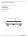
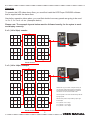
www.prolight.co.uk
LEDJ V1 Video Floor
CODE: LEDJ77
WARNING
FOR YOUR OWN SAFETY, PLEASE READ THIS USER MANUAL CAREFULLY
BEFORE YOUR INITIAL START-UP!
CAUTION!
Keep this equipment away from rain,
moisture and liquids.
SAFETY INSTRUCTIONS
Every person involved with the installation, operation & maintenance of this
equipment should:
-
Be competent
-
Follow the instructions of this manual
CAUTION! TAKE CARE USING THIS EQUIPMENT!
HIGH VOLTAGE-RISK OF ELECTRIC SHOCK!!
Before your initial start-up, please make sure that there is no damage caused during
transportation. Should there be any, consult your dealer and do not use the
equipment.
To maintain the equipment in good working condition and to ensure safe operation, it is necessary
for the user to follow the safety instructions and warning notes written in this manual.
Please note that damages caused by user modifications to this equipment are not
subject to warranty.
2.
IMPORTANT:
The manufacturer will not accept liability for any resulting damages caused
by the non-observance of this manual or any unauthorised modification to the
equipment.
• Never let the power-cable come into contact with other cables. Handle the power-cable
and all mains voltage connections with particular caution!
• Never remove warning or informative labels from the equipment.
• Do not open the equipment and do not modify the equipment.
• Do not switch the equipment on and off in short intervals, as this will reduce the
system’s life.
• Only use the equipment indoors.
• Do not expose to flammable sources or gases.
• Always disconnect the power from the mains when equipment is not in use or before
cleaning! Only handle the power-cable by the plug. Never pull out the plug by pulling the
power-cable.
• Make sure that the available voltage is between 110v/240v.
• Make sure that the power-cable is never crimped or damaged. Check the equipment and
the power-cable periodically.
• If the equipment is dropped or damaged, disconnect the mains power supply immediately.
Have a qualified engineer inspect the equipment before operating again.
• If the equipment has been exposed to drastic temperature fluctuation (e.g. after
transportation), do not switch it on immediately. The arising condensation might damage
the equipment. Leave the equipment switched off until it has reached room temperature.
• If your product fails to function correctly, discontinue use immediately. Pack the unit
securely (preferably in the original packing material), and return it to your Prolight dealer
for service.
• Only use fuses of same type and rating.
• Repairs, servicing and power connection must only be carried out by a qualified
technician. THIS UNIT CONTAINS NO USER SERVICEABLE PARTS.
• WARRANTY; One year from date of purchase.
OPERATING DETERMINATIONS
If this equipment is operated in any other way, than those described in this manual,
the product may suffer damage and the warranty becomes void.
Incorrect operation may lead to danger e.g.: short-circuit, burns, electric shocks,
lamp failure etc.
Do not endanger your own safety and the safety of others!
Incorrect installation or use can cause serious damage to people and property.
3.
Please read this user manual before operation.
Specification
2,304 pixels per panel
15mm Plexi glass support up to 550kgs (evenly distributed)
RJ-45 in/out sockets
IEC power in/out sockets
Height adjustable via feet
Power consumption: 253W
Power supply: 110V/240V 60HZ/50HZ
Size: 1000 x 1000 x 87mm
Weight: 43kgs
Panel Overview
Power Out
Power In
RJ-45 In
Rubber
RJ-45 Out
Height Adjustable Feet
4.
Rubber
Operation
To operate this LED video dance floor, you must first instal the LED Player 501B/502 software
that is supplied with the dance floor.
Also before operation takes place, you must first decide how many panels are going to be used
i.e 3 x 2, 3 x 3 or 4 x 4 etc. (examples below)
Please note: The example layouts below must be followed exactly, for the sytem to work
and display correctly.
2 x 3 (144 x 96px) examle:
5
4
1
6
3
2
Out
In
Point of view
3 x 3 (144 x 144px) example
7
6
1
8
5
2
Out
In
Please set up your choice of layout exactly as
you see here, with all floor panel connections
on the left hand side and making sure that the
connecton is in the same number order.
The first panel in the chain should always be the
top right panel.
9
4
Point of view
NOTE: Each panel is 48px wide by 48px high.
for example:
3
2 x 3 panels = 96 x 144px
3 x 3 panels = 144 x144px
4 x 4 panels = 192 x 192px
5.
LED Player 501B/502 software
Software features:
• The system doesn’t need to have a sender card. With a single ordinary network
cable, the system can perform all signal transmitting tasks.
• The network sockets on the Led Player 501B/502 control card are
10Mb/100Mb/1000Mb self-adaptation.
• The system supports 16-bit colours and the number of colours supported is 281474976710656.
• Once the hardware connection is established, the control software Led Player
2.9.12 will be used to perform all the operations.
• The system can automatically refresh the screen frequency, by computing a value
between 60Hz and 20000Hz.
• The LED screen frequency is unrelated to the video card in the controlling
computer, and can be adjusted to any value.
• The system allows the user to adjust the gray level between the level 0 and the level 65536.
• The system supports multiple LED screens.
• The system supports dot-by-dot correction.
• The system supports 1/16 or higher scanning mode.
• The value of the brightness can be adjusted between 0 and 256.
• The system can be easily upgraded by upgrading the control software Led Player 2.9.12.
• The system allows a distance of 200 meters between the control computer and the
screen with an ordinary network cable, or a longer distance with a single-mode optical fiber cable.
• The network socket on the Led Player 501B/502 control card can be used as
either a receiving socket or a sending socket.
• The system allows the γ-correction to be applied independently to any of the
red, green and blue colours.
• With the “Intelligent Setup” option provided by the system, an LED screen can
be configured and adjusted easily and quickly.
• The Led Player 501B/502 control card can automatically obtain the IP address.
Player features:
• Easy to learn and use.
• It works with the Windows 98, 2000, XP, Vista and Window 7.
• It allows the screen to be divided into numerous viewing areas (windows).
• It supports many media file formats such as MPG, AVI, SWF, WMV and WMA.
• It can play text. pictures and videos, and has more than 50 special visual effects.
• It can be timed to play.
• It can capture the screen image.
The Specification of the Led Player 501B/502 Control Card:
• The maximum number of controlled pixels: 1024 x 1024.
• Refreshing rate: 60Hz-20000Hz.
• Gray levels: 0-65536 (any of the red, green and blue colours).
• Scanning mode: 1/16 or higher.
• Signal transmission: TTL.
• Power supply: 5V DC 1000MA.
• Working environment: -25˚ to 55˚.
6.
Installation
To install the LED player, simply copy the “Led Player 2.9.12.exe” from the CD to the hard disk,
and double click the file icon to run the software.
Preparation:
Before connecting the computer to the Led Player 501B/502 control card (floor panel), the
computer’s IP address must be set up properly. Firstly, find the “My Network
Places” icon on the desktop or by pressing the “Start” button”. Then right click the icon
to see a popup menu and click the “Properties” item on the menu (Fig.1).
A window then appears to show all the connections in the computer. Find out the “Local Area
Connection” icon and right click the icon to see a popup menu (FIG.2.). Then click the
“Properties” item on the menu to see a “Local Area Connection Properties” window.
On the “Local Connection Properties” window, you will see a list of items. Highlight the last item
“Internet Protocol (TCP/IP)”, and click the “Properties” button below the list. Then an “Internet
Protocol (TCP/IP) Properties” window will appear. On this window, you will have to manually
type an IP address, the subnet mask and the default gateway for the computer (Fig. 3). Normally,
the IP would be 192.168.18.38 (or you can choose one between 18.2 and 18.38). The subnet
mask is 255.255.255.0. The default gateway is 192.168.18.1. There is no need to set up the DNS.
Fig 1.
Fig 3.
Fig 2.
7.
The Software Configuration
Running the Control Software
To run the control software “Led Player 2.9.12.exe”, double (left) click the icon of this software.
Then a window appears to allow the user to choose a language (Fig.4). Select your language and
click the “OK” button, then a “Choose your screen” window appears to allow the user to choose
the screen/panel amount (Fig. 5). Choose the number of screen/panels and click the “OK” button.
Then the program main widow appears (Fig. 6). The title of the main widow indicates the current
screen number. If the control card doesn’t start, or haven’t finished starting and the user clicks the
“Start” button or starts to play a media file with this software, then a message box will pop up to
indicate that “The current screen is not ready, and you will have to check the settings or the
connection. The number of the current screen/panels will also be indicated.
Fig 4.
Fig 5.
Fig 6.
8.
Quick Start Set Up
For a quick start set up, follow the instructions below.
Once that you have set up the correct IP address and connected all of your panels in the correct
order (see page 5), open the LED player and click on the “Config” (Fig 7.) button and type in the
password “666” (Fig 6.) and click OK.
Fig 7.
Fig 8.
In the screen config window (Fig 9.) change the “Scan Mode” to “1/4 Scan” and click on the
“Restore” button and choose the “2304 Pixels PH20.cfg” (Fig 10.) file and a window will appear
to restart the software (Fig 11.), simply press OK.
Fig 10.
Fig 9.
Fig 11.
9.
Quick Start Set Up
Once the software has restarted go back into the “Screen Config” (Fig 15.) and click on the
“Cards Array” (Fig 12.) button and click on “Auto Sort” (Fig 13.).
Fig 13.
Fig 15.
Fig 12.
Fig 14.
Once the software has found all the connected cards please make sure that each card is set to
48 x 48px and that they are numbered in the correct order (Fig 14.). To correct the order simply
click on each box in corresponding order starting from the top right (see page 5). When you are
happy with the settings click the “OK” button (Fig 15.) and save the config to the control card
(Fig 16.).
Viewing
window
(CLIPPING)
Fig 16.
Fig 17.
Once it has saved the settings to the control card you will notice that “Width” and “Height” have
been adjusted accordingly to the configuration. Now click on the start button and the designated
control cards (panels) should be lit with a clipping (Fig 17.) of your desktop on the computer from
the viewing window (Fig 17.).
10.
Quick Start Set Up
To create/upload your own picture slide show or video, click on the play button and a new window
will appear (Fig 18.). Hover over the white blank space on the left of the window and right click to
add a step (Fig 19.). Now right click on the “Step” go to “Add Window” and go across to click on
“File Window” (Fig 20.). In the file window the width and height will need to be adjusted to the
same size as the viewing window. Now click on the “Insert” (Fig 21.) button to insert any one of
the following formats; MPG, AVI, SWF, WMV, WMA, JPG, JPEG, GIF and BMP.
Fig 18.
Fig 19.
Fig 20.
Fig 21.
When you are happy with your choice you can preview it first in the viewing window by clicking on
each file in the file window or you can simply press the “Play” button for it to output to the LEDJ
LED Video Floor System.
Always be sure to save your file to your desktop or dedicated folder, so you can simply go back to
any file.
To save your file click on the “Save” button and give it your own name i.e my file.xml and click on
the “Save” button.
To re-open your saved file at any time, simply click on the “Open” button (Fig 18.), find your saved
file and click “Open”.
11.
Optional Advanced Settings
Once you have opened the LED player, you will see that there several parameters that you can
edit which relate to the size of the LED screen and the location of the viewing frame.
1) Width: Horizontal pixel points of the LED panel. It can only be set when the
viewing window frame is turned off.
2) Height: Vertical pixel points of the LED screen. It can only be set when the
viewing window frame is turned off.
3) Point X: Is where the top left corner of the viewing window frame is shown at the computer.
The X-position can be changed in real time when you use the mouse to drag the
viewing window frame, or you can input the specific value and click on “Refresh” to adjust the
viewing window frame size precisely. This setting can be done when the viewing window frame
is turned on.
4) Point Y: Is where the top left corner of the viewing window frame is shown at the computer.
The Y-position can be changed in real time when you use the mouse to drag the
viewing window frame, or you can input the specific value and click on “Refresh” to adjust the
viewing window frame size precisely. This setting can be done when the viewing window frame
is turned on.
12.
Optional Advanced Settings
Scan Mode: There are 5 scanning modes available: the 1/16 mode, 1/8 mode, 1/4 mode, 1/2
mode and static mode. Click the Drop-down list and choose the scanning mode corresponding to
the screen’s specification.
Unit/Line: Every single unit has 16 pixels. The total number of units controlled by a single line,
during a single screen refreshing, equals the total number of pixels controlled by a single line
divided by 16. The value of this parameter is a value between 1 and 32 inclusive. For example,
to a standard screen having 320 x 240 pixels, using 1/8 scanning mode and being controlled by a
single controller, during a single refreshing, the number of pixels controlled by a line is 320, thus
the number of units controlled by a single line is 20 (320/16=20).
Output Data: Each controller has 8 16-pin output ports. Each port has 2 groups of RGB data to
output.
Module: After setting up the three parameters mentioned above, click the “Apply” button and the
“Module” area will display the current configuration information. This area also shows the
dimensions and specification of a screen controlled by a single controller. The screen’s dimensions
and specification are calculated by the current configuration information. You can check the
information by viewing this area.
CLK Frequency: CLK frequency is the clock frequency outputting to the screen. It can be set
up considering the following things: the manufacturer of the screen, the technique level and the
screen working environment. If the making material and the working environment allow you to
choose the CLK sub-frequency as small as possible, then please do that to obtain the maximum
clock frequency and the maximum refreshing frequency. The range of the CLK sub-frequency is 2
to 100, corresponding to the range of the clock frequency: 25MHz to 500KHz. After the setup,
click the “Apply” button and the clock frequency will be displayed.
If the manufacturer of the panel, the technique level and the working environment cannot satisfy
a certain frequency, you may increase the CLK sub-frequency and use a low CLK frequency to
ensure the signal output.
Duty Ratio: It is the clock duty ratio. By changing this parameter, lower CLK sub-frequencies can
be set. Normally, this parameter is set to 50 (%).
Row Delay: If some rows on the screen have unexpected brightness, changing this parameter
may solve the problem by setting it to 3000 for a double-colour screen, or 200 for a full-colour
screen. If the problem still exists, then you can try to increase the value of this parameter. If the
value has been highly increased but the problem still exists, please ensure that the connection
between the receiving card and the screen has been properly established.
Blanking Delay: Changing this parameter may improve the display of the screen, which has the
effect of rows having unexpected brightness.
Control Card Type: This selection allows you to choose the type of the current control card (i.e.
controller).
13.
Optional Advanced Settings
Scan Line Order: It is the permutation of scanning lines carrying data sequences.
Empty pin: If the screen uses the 595 IC drivers, then for this selection you can choose:
“Q0-Q4”, “Q3-Q7”, “Q0-Q7”, “Q3-Q4” or “none”.
Gray level: Normally, the value of this parameter can be set to either 256 for the double-colour
screen, 4096 for the full-colour indoor screen, or 16384 for the full-colour outdoor screen. This
parameter can be also set to a larger value according to the actual demand. A larger value for this
parameter allows the screen producing images to be more distinct.
Dynamic Decode: If the screen’s IC driver doesn’t have a 138 Decoder, you need to select the
“Dynamic Decode” to allow the control card to provide the function of decoding.
Data Group Exchange: If the image obtained by the control software contains an upper portion
and a lower portion, and the LED screen makes them swap places with each other, then you need
to select the “Data Group Exchange” to solve the problem.
Red Exchange to Blue: If the red image obtained by the control software becomes blue when
being shown on the screen, then you need to select the “Red Exchange to Blue” to solve the
problem.
RGB 3 in 1: If the “RGB 3 in 1” is selected, then the three data sequences representing the three
primary colours will be sent via a single data pin.
Synchronous refresh: If the screen is controlled by more than 10 control cards, then you need to
select the “Synchronous refresh” to make the screen portions, each of which is controlled by a
different control card, display a whole image synchronously.
Scan Order: To a screen using non-static scanning, if the image obtained by the control software
contains an upper portion and a lower portion, and the screen makes them swap places with each
other, then you need to set up the “Scan Order” with either “Standard” or “Backward Order” to
solve the problem.
ST Polarity: If the control software is obtaining an image containing multi-colour stripes and the
screen doesn’t display the image correctly, then you need to set up the “ST Polarity” with either
“Highness” or “Lowness” to solve the problem.
Data Polarity: If the image obtained by the control software is black-white contrary to the image
shown on the screen, then you need to set up the “Data Polarity” with either “Anode” or
“Cathode” to solve the problem.
OE Polarity: If some dots on the screen have unexpected brightness before/after control
software’s obtaining an image, then you need to set up the “OE Polarity” with either “Highness”
or “Lowness” to solve the problem. For the “Pixels Arrange and Colour Setup” section, you can
select the “Standard mode”. The “Standard mode” indicates that the pixel points are in a linear
sequence.
14.
Intelligent Setup:
To use the “Intelligent Setup”, in the “Pixels Arrange and Colour Setup” section, select the
“Intelligent Setup” and click the button “Intelligent Setup” (Fig. 7-8). Before the setup, make
sure that the connection between the control card and the IC driver board is properly established,
otherwise the “Intelligent Setup” can’t recognize your screen panel properly.
During the intelligent setup, the user operates the control software watching the screen panel
carefully, because all the operations must follow the panel’s reactions.
1) As mentioned above, click the button “Intelligent Setup” (Fig. 7-8), and the “Intelligent Setup”
wizard will appear.
2) Choose the type of the screen (Full-colour real pixel or Double-colour Screen).
3) Enter the number of pixels of a module (i.e., unit panel) and its width (X) and height (Y).
4) The “Data num per port” indicates the number of groups of RGB data to be inputted to
15.
Intelligent Setup:
5) On the “Setup 2” window (Fig. 7-10), observe the unit panel’s reactions in Status 1 and then
Status 2. Then choose the proper description indicating its reactions. For example, if the panel
is dark in Status 1 but bright in Status 2, then choose the “Status 1 is darkness, status 2 is
brightness” on the drop-down list for the “Screen status”. Then click the “Next” button.
6) On the “Setup 3” window (Fig. 7-11), Compare Status 1 with Status 2 by watching the unit
panel’s reaction to see in which status the unit panel is brighter. For example, if the panel is
brighter in Status 1 than in Status 2, then choose the “Status 1 is brighter than status 2” on
the drop-down list for the “Screen status”. Then click the “Next” button.
16.
Intelligent Setup:
7) On the “Setup 4” window, observe which colour the unit panel is showing in each status.
For example, if the panel is showing the red colour in Status 1, the green colour in Status 2
and the blue colour in Status 3, then select the “Red” on the drop-down list for the “Status
1”,
the “Green” for the “Status 2” and the “Blue” for the “Status 3”. Then click the “Next” button.
8) On the “Setup 5” window, observe the unit panel’s reactions while its status is changing from
Status 1 to 5. Then choose the description indicating the panel’s reaction for the corresponding
status one by one. For example, if the panel is brightness-darkness striped in the Status 5, then
select the “Cross striation” for the “Status 5”. Then click the “Next” button.
17.
Intelligent Setup:
9) On the “Setup 6” window, observe the unit panel’s reaction in Status 1, and choose the
description indicating the reaction on the drop-down list for the “Screen Status”. Then observe
the panel’s reaction in Status 2 and again choose the description for the “Screen Status”. For
example, if the panel’s upper portion is bright or the whole panel is bright in the Status 1, then
select the “Status 1 is Upper half brightness or all brightness” on the drop-down list for the
“Screen Status”. Then click the “Next” button.
10) On the “Setup 7” window, there is a grid. This grid represents the unit panel being tested.
Each cell on the grid represents a pixel on the panel. Observe the panel to find out the first
bright pixel, and click the corresponding cell on the grid. You need to repeat this operation for
a number of times depending on how many pixels are on the panel. Each time when you see
a bright pixel appears on the panel, you click the corresponding cell on the grid. When all the
cells have been clicked, a dialogue window will pop out. Click the “OK” button on the dialogue
window to finish the “Intelligent Setup”.
After finishing the “Intelligent Setup”, the system will automatically set up the “Scan Mode”,
“Scan Order”, “ST Polarity”, “Data Polarity”, and the “OE Polarity” according to the
configurations made by the “Intelligent Setup” and the system will also know if the
“Red Exchange to Blue” should be applied.
18.
Module Array:
The “Module Array” window is used to tell the system how many modules (i.e., unit panels) each
control card can control, and the order followed by the unit panels when they were connected to a
control card.
In the picture above, enter the number of unit panels (X) controlled by a control card in the
horizontal direction in the “Width” text field, and the number of unit panels (Y) controlled by a
control card in the vertical direction in the “Height” text field. Then a grid with the width X & height
Y will appear on the window. Each cell on the grid represents a unit panel. Now observe the whole
screen by facing it, and click the cells one by one in the same order as the order followed by the
corresponding unit panels when they were connected to a control card. After clicking all the cells,
click the “OK” button to finish the module array configuration. If you enter the new width value
and/or new height value, the grid will be re-drawn. After the module array configuration, the system
will automatically set up the “Unit/Line” and the “Output Data”.
Cards Array:
The “Cards Array” window (Fig. 7-17) is used to tell the system, on the entire screen, the
location of the image produced by each control card. On the window, enter the number of control
cards installed in the horizontal direction in the “Horizontal Cards” text field, and the number of
control cards installed in the vertical direction in the “Vertical Cards” text field. Then a grid will
appear on the window. Each cell on the grid represents a control card. Then click the cells one by
one in the same order as the order followed by the corresponding control cards when they were
being assigned an IP address. After clicking all the cells, click the “OK” button to finish the card
array configuration.
19.
Cards Array:
If a screen has a blank area (without any unit panel), then you need to configure the cell(s)
corresponding to the control card(s), which could control the area if the area were not blank. On
the “Cards Array” window, click a cell representing a card “controlling” the blank area. Then
enter the “0” in the “Index” text field, and enter the values for “Start X” and “Start Y”, which
indicate the coordinates of the top-left pixel on the blank area “controlled” the card. Repeat the
operation for all the cells “controlling” the blank area.
After the configuration, click the “OK” button. If any error occurs, a message box will pop out to
indicate the error. Then please check the configuration.
Playing Media Files:
To create a play list for the screen, click the “Play” button on the control software’s main window,
and the window expands (Fig 22.). To add a “Step” for the play list, move the mouse cursor into
the white area and click the right button on the mouse to let a menu pop out. On the menu, select
the item “Add Step” to add a step.
To add a “File Window” for the “Step”, move the mouse cursor onto the “Step” text and right
click on the text to let a menu pop out. On the menu, select the item “Add Window”, and a
sub-menu appears. Then select the item “File Window” on the sub-menu (Fig 23.).
Fig 22.
20.
Fig 23.
Playing Media Files:
Click the “File” text and follow the steps shown in the (Fig 24.) to insert a media file into the “File”
window and let the screen play the media file:
You can add any number of files into a “window”. The control software supports numerous file
types including: text files (TXT), all the image files (e.g., BMP, JPG, GIF, PCX, WMF and ICO) and
all the media files (e.g., AVI, MPG, WMV, and SWF).
The screen can be divided into multiple windows (portions) when it is playing the media files (Fig.
24 & 25). Each window can play different media contents independently.
The Playing Window:
Fig 24.
Fig 25.
The playing window displays almost everything the LED screen displays (Fig 26.). Thus you can
think that the playing window “is” the LED screen.
Playing
window
Fig 26.
21.
Control Window
The control window (Fig 27.) is the control panel, on which you can control the LED screen’s
display. You can set up the location and size of a window (i.e., viewing frame) on the LED screen
and insert media contents for the window. There are some buttons on the control window. For example, the button “Play”, “Pause” and “Stop” are used to control the screen’s playing state. The
button “Open” and “Save” are used to open a play list from a file and save a play list to a file
respectively.
On the control window, you can configure a program (i.e., “Step” or “Universal”) or a window
(“File”) by clicking the program’s name “Step” or the window’s name “File” on the left-side white
area (Fig 27.) and the right-side area will show the properties of the program or the properties of
the window correspondingly. Then you can edit the properties of the program or its window on the
right-side area. To edit an inserted media file, highlight the file path on the file list and the file’s
properties will be shown under the list (Fig 27.).
Control
window
Fig 27.
22.
Features Of The Control Software:
a) Buttons on the Control Window
There are several buttons on the control window including: the button “New”, “Open”, “Save”,
“Play”, “Pause” and the “Stop” (Fig 27.). Clicking the “New” button clears the white area on the
control window to allow you to create a new play list. Clicking the “Open” button opens an existing
play list in a file. Clicking the “Save” button saves the current play list in a file. Clicking the “Play”
button allows the LED screen to play the media contents. Clicking the “Pause” button allows the
screen to pause. Clicking the “Stop” button allows the screen to stop playing.
b) The Pop-out Menu
Right click on the white area on the control window (Fig 23.), and a menu will pop out. There are
several items on the menu: the item “Add Step”, “Add Universal”, “Add Window”, “Page Up”,
“Page Down” and the “Delete”. To move up/down a program/window, right click the program/
window’s name on the white area to let the menu pop out. On the popped out menu, click the item
“Page Up”/“Page Down” to move up/down the program/window. To delete a program/window,
right click the program/window’s name on the white area to let the menu pop out. On the popped
out menu, click the item “Delete” to delete the program/window.
c) Setting up the Properties for Programs, Windows & Files
The control window (Fig 27) can be divided into two portions: the left side white area and the right
side configuration panel. The left side white area shows a tree structure. A program (“Step” or
“Universal”) is a node on the tree, and it can have one or more child nodes, i.e., windows. By
clicking a node’s name on the left side white area, the right side configuration panel shows the
node’s properties. If the node is a window, the panel will also show a media file list associated with
this window. Highlight a file on the list, and the file’s properties will be shown below the list.
Click a “Step” programme’s name on the tree, and the right side configuration panel shows the
programme’s properties to allow you to modify or set up. These properties include: the programme
name, the playing time, the background colour, the background picture and the display mode of
the background picture. For the “Universal” programme, only one property is allowed to modify
and that is the background colour.
Click a window’s name on the tree, and the right side configuration panel shows the window’s
properties to allow you to modify or set up. These properties include: the window’s name, the
border style, the border colour, the coordinates of the left-top point of the window, the window’s
width & height and the window’s file list.
A window’s file list contains numerous files. Highlight a file on the list and the properties of the file
will be shown below the file list (Fig 27.) to allow you to modify or set up. For a video file, its
properties include: the colour of the background where the file will be played, the picture of the
background and the display mode of the picture of the background.
For a text file, its properties include: the colour of the background, the picture of the background,
the display mode of the picture of the background, the display method (action) for the text file, the
text visual effect, the colour of the visual effect, the row spacing, the display speed, the staying
time on the screen, the font of the text and the colour of the text.
23.
Features Of The Control Software:
For an image file, its properties include: the colour of the background, the picture of the
background, the display mode of the picture of the background, the display method (action) for
the image file, the display mode of the image file, the display speed, the staying time on the screen
and the removal method (action) & the removal speed for the image file.
d) Adjusting the Viewing Frame on the Playing Window (LED Screen)
To adjust the size of the viewing frame of a window on the playing window (LED screen), click the
window’s name on the tree and its default viewing frame appears on the playing window. Then
right click on the default frame to let a menu pop out and select the menu item “Size” to see the
sub-menu (Fig 28.). Select a menu item on the sub-menu to adjust the size of the frame.
Fig 28.
Fig 29.
Select the item “Full Screen” on the sub-menu “Size” to make the frame fully occupy the entire
LED screen. Select the item “Horizontal Full” to make the frame’s width equal the screen’s width
but the frame’s height remains. Select the “Horizontal 1/2”, “Horizontal 1/3” or “Horizontal
1/4” to make the frame’s width equal the 1/2, 1/3 or 1/4 of the screen’s width respectively but the
height remains. Select the “Vertical Full” to make the frame’s height equal the screen’s height but
the width remains. Select the “Vertical 1/2”, “Vertical 1/3” or “Vertical 1/4” to make the frame’s
height equal the 1/2, 1/3 or 1/4 of the screen’s height respectively but the width remains.
To adjust the position of the viewing frame of a window on the playing window (LED screen), click
the window’s name on the tree and its default viewing frame appears on the playing window. Then
right click on the default frame to let a menu pop out and select the menu item “Position” to see
the sub-menu (Fig 29.). Select a menu item on the sub-menu to adjust the position of the frame.
Select the “Centre” to make the frame stay on the centre of the screen. Select the
“Horizontal Centre” to make the frame move horizontally to the centre of the width of the screen
but the frame’s vertical position remains. Select the “Vertical Centre” to make the frame move
vertically to the centre of the height of the screen but the frame’s horizontal position remains.
Select the “Left” or “Right” to make the frame move horizontally to the left or right end of the
width of the screen respectively but the frame’s vertical position remains. Select the “Top” or
“Bottom” to make the frame move vertically to the upper or lower end of the height of the screen
respectively but the frame’s horizontal position remains.
24.
Setting Up The Screens Brightness:
On the control software’s main window, there is a brightness slider bar (Fig 30.). By using the
slider bar, you can adjust the brightness of the screen. If the screen is working with the Led Player
501B/502 control card, then the slider bar won’t function. In this case, you need to adjust the
related parameters on the “Module Standard” window in order to control the brightness.
Colour Revision:
Fig 30.
Click the “Colour” button on the control software’s main window, and the “Colour Revise”
window appears (Fig 31.).
Fig 31.
The colour revision includes the gamma revision, contrast revision and the chroma revision. You
can perform the colour revision while the screen is working and all the changes you made will be
applied immediately on real time. When doing the colour revision, make any change by considering the screen’s working environment and the materials making the screen. The default value for
every parameter in the colour revision is 50. If you have made lots of errors and don’t want to
correct them one by one, then you just need to click the “Default” buttons on the window (Fig 31)
to restore the default value for every parameter. Please note that the default value is not always
the best. Consult the manufacturer of the screen for the correct value of every parameter in the
colour revision.
25.
Gamma Revision:
Gamma revision compensates the loss of image details caused by the linear distribution of gamma
values during the anti-aliasing process, which makes the image much smoother and much more
distinct.
On the “Colour Revise” window (Fig 31.), you can either simply drag the slider(s) in the
“Gamma Revise” section to adjust the gamma value, or manually edit the gamma value for a
gray level in the range of 0 to 255 in the “Gamma Custom” section.
In the “Gamma Revise” section on the “Colour Revise” window (Fig 31.), the gamma slider bar
range is from 0 to 100. A number in this range is corresponding to an actual gamma value. Adjust
the gamma value by considering the screen’s working environment and the materials making the
screen. Consult the manufacturer of the screen for the proper gamma value.
The “Gamma Custom” section (Fig 31.) allows a user to manually edit the gamma value for a
gray level in the range of 0 to 255. Normally, you don’t need to edit gamma values manually.
The synchronous revision: In the “Gamma Revise” section, tick the box indicating the
“Synchronize” (Fig 31). Then drag the slider on the gamma slider bar or click the “up/down”
arrow to adjust the gamma value. In this case, the gamma values of red, green and blue will
synchronize.
The asynchronous revision: In the “Gamma Revise” section, clear the box indicating
the “Synchronize” (Fig 31.). Then the red, green or blue gamma value can be adjusted
independently according to the specifications of the screen.
The “Gamma Custom”: In the “Gamma Custom” section, you can manually edit the gamma
value for a gray level in the range of 0 to 255.
Contrast Revision:
The contrast revision is based on the histogram revision (Fig 31.). The image is revised by using
the non-linear adjusting curve to achieve the best visual effect. The contrast slider bar rang is from
0 to 100. Different numbers in this range are corresponding to different contrast S curves. Adjust
the contrast value by considering the screen’s working environment and the materials making the
screen. Consult the manufacturer of the screen for the proper contrast value.
The synchronous revision: In the “Contrast Revise” section, tick the box indicating
the “Synchronize” (Fig 31). Then drag the slider on the contrast slider bar or click the “up/down”
arrow to adjust the contrast value. In this case, the contrast values of red, green and blue will
synchronize.
The asynchronous revision: In the “Contrast Revise” section, clear the box indicating the
“Synchronize” (Fig 31.). Then the red, green or blue contrast value can be adjusted
independently according to the specifications of the screen.
26.
Chroma Revision:
The colour blending of red, green and blue may lean to a certain hue due to the materials making the screen ect. To accurately identify some chroma problems such as the color cast problem
and the low saturation problem, and to solve these problems by adjusting the chroma value in the
“Chroma Revise” section (Fig 31.), you need to know the values of gray levels of the red, green
and blue. In the “Chroma Revise” section, the chroma slider bar range is from 0 to 100. Different
numbers in this range are corresponding to different chroma values. Adjust the chroma value by
considering the screen’s working environment and the materials making the screen. Consult the
manufacturer of the screen for the proper chroma value.
The synchronous revision: In the “Chroma Revise” section, tick the box indicating the
“Synchronize” (Fig 31.). Then drag the slider on the chroma slider bar or click the “up/down”
arrow to adjust the chroma value. In this case, the chroma values of red, green and blue will
synchronize.
The asynchronous revision: In the “Chroma Revise” section, clear the box indicating
the “Synchronize” (Fig 31.). Then the red, green or blue chroma value can be adjusted
independently according to the specifications of the screen.
Setting Up A Message:
To set up a message that will be shown on the screen, type the message in the “Message” text
field or copy the text of the message to the text field. Then click the “Refresh” button (Fig 32.).
Fig 32.
Fig 33.
27.
Setting Up A Message:
To set up the moving style of the message, click the “Moving” button on the control software’s
main window (Fig 32.) and the “Moving” window will pop out (Fig 33.). On the “Moving” window,
you can configure the following moving properties for the message:
1) The “Moving Orientation”: This property indicates the moving direction. “Left” means that the
message moves from the right side of the screen to its left side. “Right” means that the message
moves from the left side of the screen to its right side. “Up” means that the message moves from
the bottom of the screen to its top. “Down” means that the message moves from the top of the
screen to its bottom. “Static” means that the message stands still on the screen.
2) The “Words Position”: This property indicates the position of the message on the screen.
“Top” means that the message will be shown on the top of the screen if the “Left” or “Right” is
selected. “Centre” means that the message will move keeping on the middle of the height of the
screen if the “Left” or “Right” is selected. “Bottom” means that the message will be shown on
the bottom of the screen if the “Left” or “Right” is selected.
3) The “Moving Speed”: This property indicates the speed of the moving message. The speed
slider bar range is from 1 (pixel per second) to 100 (pixels per second). Adjust the speed by
dragging the slider to a proper value (Fig 33.).
After setting up the moving style, click the “OK” button to apply the configuration or the
“CANCEL” button to give up the configuration (Fig 33.).
To set up the font of the text of the message, click the “Font” button on the control software’s
main window (Fig 31.) and the “Font” window will pop out (Fig 34.). On the “Font” window, you
can configure several properties for the text of the message including the font, the font style, the
font size and the font colour. The “Sample” section reflects your configuration. After setting up the
font, click the “OK” button to apply the configuration or the “Cancel” button to give up the
configuration (Fig 34.).
Fig 34.
28.
Auto Play Function:
To activate the auto-play function, click the “Auto” button on the control software’s main window
(Fig 32.) and the “Edit Schedule” window will pop out (Fig 35.). On the “Edit Schedule” window,
tick the box indicating the “Auto Play” and set up the start time and the finishing time. Then click
the “OK” button. When the start time comes, the control software will automatically switch on the
LED screen and load the last saved/played play list to play. Then when the finishing time comes,
the control software will automatically switch off the screen. If the start time is later than the
finishing time, this will mean that the finishing time is some time on the next day. If the start time
equals the finishing time, then whenever the control software starts, it will switch on the screen
and load the last saved/played play list to play, and the play list will be played permanently.
If you manually click the “Stop” button to stop playing during the auto-play mode, the control
software will change the auto-play mode to the user-interactive mode. To restore the auto-play
mode, close the control software’s main window and re-run the software again, or re-configure the
auto-play mode on the “Edit Schedule” window (Fig 35.) and click the “OK” button.
Fig 35.
29.
30.
31.
www.prolight.co.uk