1
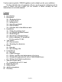
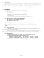
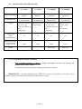
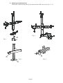
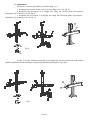
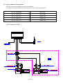
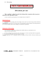
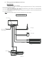
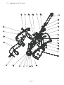
ENGLISH VERSION
INSTRUCTION
MANUAL
Reciprocating coder
T.C.
T.C.
T.C.
T.C.
24
24
24
37
x
x
x
x
24
35
48
37
ISO
ISO
ISO
ISO
BP3 - 01450 PONCIN – France
Tel. +33 (0) 4 74 37 33 80 / 97 – Fax +33 (0) 4 74 37 33 62
e-mail : [email protected]
www.Tiflex.com
PAGE 1
You have just acquired a TIFLEX appliance and we thank you for your confidence.
We hope that this item of equipment will give you the greatest satisfaction and, in
order to achieve the best results, you are advised to follow carefully the user
instructions set out in this manual.
Contents
1. Introduction
2. Description
2.1 – Mechanical device
2.2 – Control device
2.3 – Inking device
2.4 – Operating principle
2.5 - Characteristics
2.6 – Selection table of the different units
3. Installation
3.1 – Fitting the printing head
3.2 – xyz brackets and bench model
3.3 – Head fitting kit
3.4 – Bench unit “bottom marking”
3.5 - Kit for additional TC printhead
3.5.1: Layout for TC Kit :
4. Type holder
4.1 - Characteristics
4.2 – Mounting the characters
5. Inking
5.1 - Principle
5.2 – Ink cartridge CM
6. Control boxes
6.1 - Principle
6.2 – Choice of trigger
6.3 – Wiring, operation and adjustments of the boxes
6.4 – Wiring of the photoelectric cell on T202/CBM402 boxes
6.5 – Wiring of jack limit stop detectors
7. Main list of spare parts
7.1 – Exploded view of T.C. head
8. Replacing the jack
9. Choice of inks
10. Additional products
11. Warranty
PAGE 2
1.
Introduction
T.C. pneumatic printers are reciprocating units to be integrated on automatic packaging lines. They
are designed to operate at very low pressure, allowing the item to be touched extremely lightly. They are
essentially intended for dating, coding, referencing, batch numbering and price printing on absorbent and
non-absorbent substrates on continuous or intermittent run or at a manual station.
Constructed of stainless steel elements, these printers are of “foodstuff” quality.
2.
Description
2.1
The basic mechanical device consists of the following:
- the TC head
- two type holders
As an option, it can be supplemented with the following:
- 1 fastening bracket
- 1 device to lock the item (linked to the CBM 401 or 402 control box, cf. § 6).
2.2
The control device groups together the following:
- the pneumatic or electro-pneumatic control box
- the pneumatic or electric trigger.
2.3
The inking device consists of a cartridge designed for rapid drying printing.
N.B.: The T.C. printing head also exists as an independent bench station for top printing.
2.4
Operating principle
A trigger detects the passage of the item, to be printed. It forwards this information to the
control box, which controls the printing head.
At the end of the head, a type holder deposits the print on the item, and it then resumes its rest
position, thereby covering the opening of the inking cartridge and preventing the inker from drying out.
2.5
Characteristics
- 3 maximum printing formats: 24 x 24 mm, 24 x 35 mm, 24 x 48 mm,37x37mm
- overall dimensions of the head (including cartridge and jack)
formats 24 x 24 and 24 x 35 mm :
H = 205 mm ; L = 165 mm ; W = 80 mm
format 24 x 48 mm and 24 x 35 mm: H = 205 mm ; L = 181 mm ; W = 95 mm.
The T.C. head is controlled by means of all the existing pneumatic or electrical control boxes.
PAGE 3
2.6
Selection table of the different units
Conveyor operation
Permissible rate
Triggers
T.C./T201
T.C./T202
T.C./CBM401
T.C./CBM402
stepped
Stepped
continuous
continuous
120 strokes/min
150 strokes/min
60 strokes/min
60 strokes/min
- with roller sensitive - photoelectric cell
at 2.3 to 4.5 kg
- electric pedal
- with rod sensitive at
100 g
- with pedal
Control of 2
heads
simultaneously
Minimum pressure
compressed air
supply network
- with roller sensitive
at 2.3 to 4.5 kg
- with rod sensitive at
100 g
- with pedal
- photoelectric cell
- electric pedal
- PLC
- hard contact
yes
yes
yes
yes
4 bars
4 bars
6 bars
6 bars
Pulse delay
Pulse delay
Option
.
2.7 Use of printhead, witrout control box
- Max cylinder pressuve : 2 bars ( a higher atmospheric pressuve will damage the
cylinder or the valve - stem )
- Control the piston movement by adjusting the pressure restrictor .
IMPORTANT : On this installation type TIFLEX can’t give any garanty, as we have got no
certainty, that the TC has been installed and comissioned correctly .
PAGE 4
3.
Installation
3.1
Fitting the printing head
3 possibilities for fitting the head:
- fitting by your own means
- using a xyz bracket in one of its 3 versions
- the head fitting kit.
Comments on fitting the head
It can be adjusted in every direction.
It must be fixed at a specific distance in relation to the surface to be printed (see overall
dimensions, fig. A).
The xyz bracket allows precise positioning of the head by means of micrometer endless
screws. It also allows adjustment of the point of impact on the surface to be printed, by setting
the position of the head in site and inclination.
If you have opted for a mounting system designed by you, it is recommended that you envisage
one that can be adjusted in distance.
In every situation, the precision of the mounting of the head will determine the perfection of the
printing.
Under the action of a double-effect jack, the movement lies within a 90° curve with
a linear limit stop over 7 mm, both towards the item to be printed and towards the inking surface.
These two linear limit stops are controlled by adjusting the flow limiters situated on the control
box, so that the movement does not end with a mechanical impact at the ends of the guide grooves.
.
PAGE 5
75 : 24 x 24 and 24 x 35
165 : formats 24 x 24 and 24 x 35
41 : 24 x 24 and 24 x 35
181 : format 24 x 48
90 : 24 x 48
3M5 at 120° over Ø 44
X = 39 max.
X + 29 mini (adjustable with the control box)
80 : 24 x 24 and 24 x 35
.
Fig. A
3.2
xyz bracket
The xyz brackets allow precise positioning of the T.C. printing heads.
1) Installation
These brackets exist in 3 versions :
a) xyz, micrometric, fastening along a horizontal or vertical plane (fig. 1), more
particularly recommended when the items to be printed are handled manually.
b) xyz, micrometric and articulated, fastening along a vertical plane (fig. 2), for installation
at the edge of a conveyor.
c) bench model fastening along a horizontal plane (fig. 3) without micrometric
adjustments.
For all these versions, the base [1] is secured by means of four M6 screws (fig. 1, 2, 3).
PAGE 6
2) Mounting the printing head
The head is secured to the plate [2] by means of three M5 screws (see fig. 1, 2, 3).
2
2
1
Fig. 2
1
1
Fig. 1
.
2
2
Fig. 3
Fig. 4
1
PAGE 7
3) Adjustments
For these 3 versions, adjustment is possible along x, y, z.
z designates the rotation of the vertical axis (locking screw [3]) (fig. 4).
y designates the movement in a straight line along the vertical plane (micrometric
adjustment [4], locking screw [5]) (fig. 4).
x designates the movement in a straight line along the horizontal plane (micrometric
adjustment [6], locking screw [7]) (fig. 4).
4
4
5
7
5
5
6
7
6
7
3
3
Fig. 4
3
For the 2 versions with horizontal and vertical fastening, a bi-directional ball joint makes it
possible to tilt the head in site (locking screw [8]) and in inclination (locking screw [9]), (fig. 5).
9
9
9
8
8
11
8
10
Fig. 5
PAGE 8
For the vertical fastening version, 2 adjustments are still possible:
1) rotation of the unit around a vertical axis (locking screw [10])
2) distancing the unit in relation to the conveyor (locking screw [11]), (fig. 5)
Prior to each adjustment, it is essential to undo the corresponding locking screw.
These screws have an indexable handle; simply lift these handles slightly in order to allow
easy handling.
A 100 mm extension piece is available by special order, to increase the capacities of these
brackets.
3.3
Head fitting kit
The fitting kit consists of 9 main parts + fastening accessories.
7
8
5
1
6
.
4
2
3
- a fastening part for the TC head, item (2), and the fastening accessories, item (3).
- a connector, allowing rotation is 2 directions, item (1), + 2 disengageable locking handles, item (4)
- an connector/aluminium sectional bar connecting pin, rep. (5)
- a 45 x 45 aluminium sectional bar, item (6), 250 mm long
- a plate, item (8), and 2 angle cleats, item (7), for vertical and horizontal positioning
3.4
Bench unit
• T.C. head bench unit "bottom mounted"
Aluminium sectional bar unit comprising a T.C.
printing head, a T202 electrical control box, an electric
trigger, a device for adjusting the position of the item.
PAGE 9
3.5 Kit for additional TC printhead
This Kit is forseen for adding an extra TC printhead.
It include an extra printhead and 2 diversion valves and 2 tubes polyuréthane
KIT TC printhead
Reference
Kit TC 24x24 ISO
06R0024KI
Kit TC 24x35 ISO
06R0035KI
Kit TC 24x48 ISO
06R0048KI
Kit TC 37x37 ISO
06R0037KI
3.5.1: Layout for TC Kit :
.
PAGE 10
4.
Type holder
4.1
Characteristics
The type holder is mounted on a dovetail slide rail, with positioning ball. In this way it can be
removed without having to use a tool. Generally having a level surface, it can be supplied concave or
convex, according to the diagrams below, in 3 formats: 24 x 24 mm, 24 x 35 mm and 24 x 48 mm.
flat
longitudinal grooves n° 1
concave
longitudinal grooves n° 3
flat
tran sverse grooves n ° 2
concave
transverse grooves n° 4
convex
longitudinale grooves n° 5
convexe
transverse gro oves n° 6
4.2
Mounting the characters
The surface of the type holder is covered with an autoclips base, making it possible to fasten
characters, logos and type plates simply by attaching them. The autoclips principle allows text to be
changed fast, easily and when required.
5.
Inking
5.1
Principle
This is carried out by means of a saturated cartridge, whose characteristics are as follows:
- removable, without using a tool
- contains no liquid ink, allowing mounting. in every direction
- rapid drying
- reactivation by adding a volume of regenerant
- available with different qualities of inks.
PAGE 11
5.2
CM cartridge
CM CARTRIDGES
Directions for use
That cartridge is planed to print fast drying inks on porous and non porous
substrates with a pneumatic coder.
As new, it must be stored top above in a cool place between 5 and 30°C.
Instructions for use :
Immediately after opening, place the cartridge on the coder. If you wait to long, the ink would start
its evaporation.
Check that the compressed air is arriving on the coder and that the character holder is in its idle position to
be in contact with the surface of the cartridge to avoid the ink evaporation.
Maintenance of CM cartridge:
.
a) For long stops, withdraw the cartridge from its holder and screw cautiously the cover.
It has to be stored up side down.
b) If the cartridge does not ink any more the characters, it can be reactivated with our regenerator.
For the equivalent of the bottle half screw cap onto the fiber.
The regenerator 1473 is compatible with the cartridges CM 700, CM 207, CM 300, CM 4399 and
CM 500.
01450 PONCIN - FRANCE -
PAGE 12
(33) 04 74 37 33 33 – Fax (33) 04 74 37 33 45
6.
Control boxes
6.1
Principle
They have all been designed to operate pneumatically and they require the use of
oil-filtered, dry and dust-free compressed air.
For triggering, they receive a pneumatic or electrical instruction.
Boxes T201 and T202 allow rates of up to 1 stroke/second (no adjustment possible).
Boxes CBM401 and CBM402 allow rates of up to 1 stroke/second. They control successively a
device for stopping the item and the printing head.
Boxes T201 and T202 are the simplest of the series and no adjustment is possible.
6.2
Choice of trigger
The trigger detects the presence of the item to be printed; it is linked electrically
or pneumatically to the control box. It is mounted on the packaging line.
Its choice depends on the type of reader envisaged:
- by capturing information on the conveyor,
- on the item to be printed, taking into account its weight, fragility and alignment.
• pneumatic triggers
- with roller sensitive at 2.3 to 4.5 kg of thrust
- with rod sensitive at 100 g of thrust
- with pedal
- with rod sensitive at 7 g of thrust
- with ball sensitive at 7 g of thrust
}
• electric triggers
- photoelectric cell
- electric pedal
- hard contact
- PLC
}
.
PAGE 13
adapted to units
T.C./T201 and T.C./CBM401
Adapted to units
T.C./T202 and T.C./CBM402
6.3
Wiring, operation and adjustment of the boxes
BoxesT201/T202
- Carry out the wiring (see diagram).
- Actuate the rod trigger or any other trigger (idem photoelectric box CT202), to check that the
head performs its full movement.
- Carry out a printing test. The contact of the characters on the surface to be printed should
occur with a light, though sufficiently rapid, “touch”.
- If necessary, using the flow limiters situated on the control box, slow the outward and inward
travel of the printing head.
N.B.: The interval timer of the cycle time of the head is set at the factory.
T201 BOX WIRING
Flow limiters
NETWORK
Rod trigger
Filtered air 40 µ
(4 bars minimum)
.
or
Roller trigger
or
(red leadout)
Pedal
Printing head
PAGE 14
T201 BOX WIRING
220V supply
Flow limiters
Photoelectric cell
N ETWO RK
Plugged outlets
.
Printing head
PAGE 15
Boxes CBM401/CBM402
- Perform the wiring (see diagram).
- Actuate the rod trigger or any other trigger, to check that the head performs its full movement
and that the locking clip is operating.
N.B.: As the boxes are pre-set at the factory, it is necessary to check that locking occurs prior to
printing.
- Carry out a printing test. The contact of the characters on the surface to be printed should
occur with a light, though sufficiently rapid, “touch”.
- If necessary, using the flow limiters situated on the control box, slow the outward and inward
travel of the printing head.
- 2 adjustments are possible on the control box:
1) printing / locking delay
2) duration of the complete cycle time.
CBM401 BOX WIRING
Complete cycle time adjustment
Printing/locking delay adjusteme nt
Flow limiters
.
Filtered air 40µ
( 6 bars minimun )
Rod trigger
Locking clip
or
Roller trigger
or
Flow limiter clip outle t
Flow limiter clip retur n
( red le adout )
Pedal
Pr inting head
PAGE 16
CBM402 BOX WIRING
2 20 V su pply
Complete cy cle time adjustement
Printing/locking delay adjustement
Flow limiters
Filtered air 40 µ
(6 b ars minimum)
Plugged outlets
Locking clip
.
Flow limiter clip return
Flow limiter clip outlet
Prin ting head
PAGE 17
PHOTOELECTRIC CELL WIRING
T202-CBM402 BOXES
220 V supply
earth compulso ry on this plu g
brown
box lead out connector
brown
blue
yellow/green (earth)
blu e
AC 24 V and 220 V ph otoelectric cell
220 V supply
.
earth compulsory on this p lug
brown (-)
b ox leadout con nector
brown
blue (+)
yellow/green (earth)
black
DC 24 V p hotoelectric cell
PAGE 18
Blue (-)
Brown (-)
XRCC1C
LIMIT STOP DETECTORS WIRING
Electricity type
Continous
.
Voltage (volts)
75 maxi
Max electric current (mA)
180
Réaction Time (ms)
1.8
PAGE 19
7.
Main list of spare parts
Item
n°
Quantity
PARTS
Right-hand basic cheek
Left-hand basic cheek
Jack housing
Type holder
Jack
Pivot bloc
Bearing
T.C. PRINTER
1
2
3
4
5
6
7
Type holder pin 5 x 32
8
Type holder
9
Foam
10
Grooved base 24 x 24, 24 x 35 , 24 x 48 or 37 x 37
11
Spacer
12
Steel plate
13
Round head screw 5 x 10
14
Type holder pin 2
15
Barbed nipple M5
16
.
Detector M/50/LSU/2V + Gripping yoke
17 + 18
Pin 5 x 12
20
Pin 4 x 10
21
Screw CHC M4 x 16
Cartridge bracket 24 x 24
Cartridge bracket 24 x 35
Cartridge bracket 37 x 37
Cartridge bracket 24 x 48
Cartridge 24 x 24, 24 x 35 , 24 x 48 or 37x 37
Rear plate 24 x 24, 24 x 35 , 24 x 48
Rear plate 24 x 24, 24 x 35 , 24 x 48
Spring
Article code to be
specified with the order
22
23
23
23
23
24
25
25
26
PAGE 20
1
1
1
1
1
1
1
06RP01
06RP02
06RP03
06RP04
06RP55
06RP06
06RP07
1
1
1
1
2
1
6
1
2
1+1
2
2
06RP08
Sold with item 5
See price list (per cm²)
See price list (per cm²)
06RP14
06RP15
06RP16
06RP17
06RP19
06RP20
06RP25
06RP27
2
1
1
1
1
1
1
1
2
06RP28
06RP2924
06RP2935
06RP2937
06RP2948
See price list
06RP31
06RP31
06RP32
7.1
Exploded view of T.C. head
㱠Ն
PAGE 21
8.
Replacing the jack
- Cut off the air inlet.
- Remove the ink cartridge.
- Disconnect the jack hoses.
- Unscrew the 2 barbed nipples M5, item 18 (to be used again for the new jack).
- Remove the magnetic detector(s) from the jack, item 19 (detection option).
- Unscrew the 2 nuts on the jack and remove the latter.
- Fit the new jack.
N.B.: The fastening of the jack rod onto the cover determines the position of the type holder in
its top and bottom position.
擀ԁ
Adjustment: In the inking position, screw on or unscrew the jack rod, to bring the front of the
grooved base flush with part n° 26 (cartridge bracket) and lock the nut, n° 30.
- Screw back on the 2 barbed nipples M5.
- Reconnect the 2 jack hose.
- Refit the detector(s).
- Refit the ink cartridge.
- Reapply the air pressure in the circuit.
9.
Choice of inks
Consult the synoptical table of the characteristics of our inks, as well as the detailed descriptions of
each of our inks. These documents appear in our general catalogue.
PAGE 22
10. Additional products
10.1 Products for cleaning the equipment
Nettol: liquid cleaner diluting agent supplied in 5-litre tins. Check the compatibility of this diluting agent
with the ink that you use (cf. synoptical table on use of inks).
Aéronet: Aerosol cleaner diluting agent specifically recommended for the characters.
Cellulose wadding: in 800 m length rolls (approx.) and pre-cut into 40 x 30 cm formats, thus simplifying
cleaning.
10.2 Hygiene products
High protection cream: supplied in 240 ml aerosol canisters, this protects the hands and forearms from
attack by inks and solvents.
Gel soap: supplied in 5-litres tins, this removes traces of ink from the hands, whilst at the same time
softening the skin. It is biodegradable. This soap tin comes with a distribution pump and a wall bracket.
11. General conditions of warranty
This TIFLEX appliance comes with a full warranty, parts and labour, for a period of six months as
from the date of bringing into service.
The contractual warranty covers all manufacturing defects; the following cases are excluded from the
warranty:
- use in a manner not suitable for or not in accordance with its purpose
- unsuitable or defective electrical connection
- normal wear
虀Ն
- faulty maintenance
- breakdown due to non-compliance with one of the points of the user manual
- breakdown whose origin is due to an item of equipment not covered by the manual
- repair or attempted repair without the service assistance of TIFLEX or without the prior authorisation of
TIFLEX
- not using TIFLEX guaranteed genuine spare parts.
The warranty is executed following prior agreement, at the client’s premises (by our good offices or
by the latter, as appropriate) and it is understood as being the replacement of defective parts. Postage and
packing are payable by the client.
Under no circumstances may the application of the contractual warranty give rise to compensation
for direct or indirect losses.
PAGE 23